US4420868A - Trough manufacturing process - Google Patents
Trough manufacturing process Download PDFInfo
- Publication number
- US4420868A US4420868A US06/276,059 US27605981A US4420868A US 4420868 A US4420868 A US 4420868A US 27605981 A US27605981 A US 27605981A US 4420868 A US4420868 A US 4420868A
- Authority
- US
- United States
- Prior art keywords
- section
- sheet
- trough
- edges
- blank
- Prior art date
- Legal status (The legal status is an assumption and is not a legal conclusion. Google has not performed a legal analysis and makes no representation as to the accuracy of the status listed.)
- Expired - Fee Related
Links
Images


Classifications
-
- B—PERFORMING OPERATIONS; TRANSPORTING
- B23—MACHINE TOOLS; METAL-WORKING NOT OTHERWISE PROVIDED FOR
- B23P—METAL-WORKING NOT OTHERWISE PROVIDED FOR; COMBINED OPERATIONS; UNIVERSAL MACHINE TOOLS
- B23P15/00—Making specific metal objects by operations not covered by a single other subclass or a group in this subclass
- B23P15/22—Making specific metal objects by operations not covered by a single other subclass or a group in this subclass cartridges or like shells
-
- Y—GENERAL TAGGING OF NEW TECHNOLOGICAL DEVELOPMENTS; GENERAL TAGGING OF CROSS-SECTIONAL TECHNOLOGIES SPANNING OVER SEVERAL SECTIONS OF THE IPC; TECHNICAL SUBJECTS COVERED BY FORMER USPC CROSS-REFERENCE ART COLLECTIONS [XRACs] AND DIGESTS
- Y10—TECHNICAL SUBJECTS COVERED BY FORMER USPC
- Y10T—TECHNICAL SUBJECTS COVERED BY FORMER US CLASSIFICATION
- Y10T29/00—Metal working
- Y10T29/49—Method of mechanical manufacture
- Y10T29/49826—Assembling or joining
- Y10T29/49888—Subsequently coating
Definitions
- U-shaped trough sections were formed either by rolling a plate back-and-forth between three rollers, or breaking it successively to form a bend. Troughs with long sides or deep troughs could not be formed in this manner because the sides became so unwieldy in the multi-operations of increment bends until a U-shape was obtained. If shallow U-bends were first formed and then angular sides were welded thereon to provide for the pitch of the resulting trough, this took time, and was expensive and did not produce smooth and uniform troughs.
- a common central drive for two parallel shafts is known from:
- the U-shaped trough produced by the process and apparatus of this invention comprises a smooth single sheet of steel having gradually increasing depth or height parallel equal sides and a smooth round U-shaped bottom, the open top of which is provided with a flanged frame for maintaining the parallel spacing of the sides and for providing a seat for removable gratings.
- the outside of this trough may be coated with a rust-resisting coating and its parallel vertical walls may be provided bendable L-shaped tabs which when bent outwardly from their tacked ends to provide locking anchors in the concrete in which the troughs are embedded.
- troughs may be used for many purposes, but preferably have a pitch so that liquids therein will have a natural gravity flow from one end of the trough to the other, such as for the gravity and/or jet urged movement of contaminated coolant to a separator in a metal machining factory.
- the method for producing this trough comprises generally the steps of: cutting an isosceles trapezoidal sheet from a strip or web of steel with a pair of opposite parallel side edges, clamping this isosceles trapezoidal sheet near its center transversely of its parallel side edges and along the bottom of one of its resulting U-shaped sides, wrapping the longer free portion of the trapezoidal plate around a convex mandrel to form a smooth U-shaped section with sloping top edges and identical parallel sides, welding adjacent sections together along their equal length adjacent parallel side edges, that is, the base of one trapezoid to the top of the next successive trapezoid to form a sub-assembly trough, and finally welding to the open top of this sub-assembly trough a flanged frame to maintain the parallelism of the sides and also provide a seat for a grating cover.
- the parallel outside surfaces of the troughs may have tacked thereon L-shaped brackets which may be bent outwardly to form right-angled hooks for locking the trough in the concrete in which it is embedded.
- Preferably at least the outer surfaces of the trough are coated with a rust-resistant coating before being embedded in the concrete.
- the apparatus for performing these steps comprises a supply of steel sheets, either from a stack of flat sheets or a roll or web of steel, with parallel side edges, which web or sheets are fed, such as on a roller conveyor table, to a cutter which cuts the sheets transversely to form the converging or diverging ends and side edges of isosceles trapezoidal sheet sections, so that the base of one trapezoidal section is equal in length to the top of the next adjacent trapezoidal section.
- the sheet or web is clamped both along and between its parallel edges while the cutter is in operation, which cutter may be a shear or a cutting torch, such as a plasma arc torch, which torch guides itself along a pre-adjusted transverse track set according to the angle of pitch of the flow of the resulting trough.
- a cutting torch such as a plasma arc torch
- this section is conveyed further on a conveyor roller-type table which may be vertically adjustable to compensate for different thickness sheets and different size mandrels, to underneath the mandrel, such as a cylinder provided with a longitudinal peripheral axially extending rib, which rib may be oscillated about a longitudinal axis of the mandrel by means of a pair of hydraulic cylinders on opposite sides of the sheet and ends of the mandrel to engage the top of the trapezoidal section sheet along the bottom edge of one of the resulting parallel sides of the trough section, and clamp it rigidly against the supporting table.
- a conveyor roller-type table which may be vertically adjustable to compensate for different thickness sheets and different size mandrels, to underneath the mandrel, such as a cylinder provided with a longitudinal peripheral axially extending rib, which rib may be oscillated about a longitudinal axis of the mandrel by means of a pair of hydraulic cylinders on opposite sides of the sheet and ends of the mandrel
- the sheet Before the rib on the mandrel clamps the trapezoidal sheet section, it is essential that the sheet be properly aligned, which may be manually done by the operators of the machine, by hydraulically lifting a separated pair of antifriction tired wheels or rollers for supporting the sheet on each side thereof so that one or the other may be manually rotated to move the sheet angularly with respect to the mandrel for proper alignment thereof.
- the limits of oscillation of the two parallel arms may be adjusted by a manual sensing switch, and usually the bend is slightly more than 180° in order to compensate any natural spring-back or resiliency in the sheet and to form stationary parallel sides for the trough section.
- the drive for the two parallel arms of the wrapping roller is by a central single hydraulic reversible motor which is vertically and pivotally suspended between the arms.
- This motor drives through two oppositely extending toothed belts or sprocket chains identical gearing mechanisms adjacent each of the lever arms to oscillate the two arms in substantially identical sequence to insure the uniform smooth U-shaped bend in the resulting product.
- the resulting U-shaped bent sheet section or trough section is unclamped by reversing the oscillation of the mandrel rib, so the trough section can be withdrawn from the mandrel on a further roller conveyor table, and then placed in a jig so that the adjacent equal length edges of successive trough sections may be welded together to form a trough sub-assembly of several U-shaped bent trough sections which have uniform U-shaped bends with a continuous smooth contour.
- Frames having flanged edges and stepped seats then may be welded to the upper open end of the sub-assembly trough walls.
- L-shaped brackets tacked at one outer end of one of their legs, so that they may be bent outwardly when ready to be set in concrete for anchoring the walls in the concrete.
- Another object of this invention is to provide a machine which produces consistent, uniform and integral smoothly curved U-shaped bends in the center of sheets with long sides up to say about twenty feet in length with semi-cylindrical bend diameters from about eight to about twenty inches.
- Another object is to provide a simple, efficient, effective, accurate, and adjustable machine for carrying out the steps for producing such a U-shaped trough section which comprises cutting the sheets into isosceles trapezoids in which each successive sheet has one parallel side equal in length to a corresponding opposite parallel side of an adjacent trapezoidal sheet, and in which the angle of which converging or diverging end side edges correspond to the gravity flow pitch to be provided in the resulting trough for liquid transported therein.
- Another object is to provide such a machine which is adaptable and adjustable to bend U-shaped trough sections of different widths and different convex shapes, as well as different thicknesses of steel sheets.
- Still another object is to produce such a machine in which the opposite ends of the wrapping roll for bending the sheet around a relatively fixed convex mandrel are substantially completely synchronous in their operation being driven by a single motor and two gear mechanisms including flexible links having equal tension insured by the floating mounting of the intermediate motor.
- FIG. I is a schematic block diagram of the steps of the process of this invention.
- FIG. II is a side elevational view of the first two major steps of the process of this invention of feeding, clamping and cutting a sheet into an isosceles trapezoidal sheet section;
- FIG. III is a plan view of FIG. II showing another means of feeding the sheet, namely a web from a roll, and also showing the adjustable guide for cutting the angular end side edges of the isosceles trapezoidal sheet section;
- FIG. IV is a side elevation, with parts broken away, of the trapezoidal sheet section bending machine, with the bending lever shown in dotted lines in its full bending position, and with the plate-aligning means being shown in dotted lines in its plate-supporting and adjusting position;
- FIG. V is a view taken along lines V--V of FIG. IV showing the outlet side of the bending machine and the drive for the levers of the wrapping or bending roller, showing the roller in dotted lines in its full bending position;
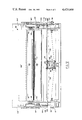
- FIG. VI is a perspective view of a trough section bent in the machine shown in FIGS. IV and V;
- FIG. VII is a perspective view similar to FIG. VI showing how trough sections may be nested together for shipping purposes;
- FIG. VIII is another perspective view of a trough section similar to that shown in FIG. VI but with temporary spacers placed between its two parallel sides to prevent their collapse until properly assembled;
- FIG. IX is a perspective view of a frame section which is to be welded onto the open top of a U-shaped trough;
- FIG. X is a perspective view of a U-shaped trough with a frame as shown in FIG. IX welded in place thereon, and part of a grating spaced above the frame to be seated therein, and also several bent-up L-shaped locking lugs on the side wall of the trough ready for anchoring the trough into its embedding concrete.
- FIG. I there is shown schematically the major steps in producing a trough in the floor for liquids such as a contaminated coolant solution from machining operations in a factory floor, a section of which troughing is shown in FIG. X.
- the steps of this process start out with a sheet of steel or other metal of which the trough is to be manufactured which may come in sheet form or may be taken from a reel or coiled web.
- the sheet or web usually comes in sheets about eight feet wide and ranges in thickness from about 1/8 inch up to 1/4 inch or more.
- This sheet material is first fed in step (A) onto a horizontal table-type conveyor, such as comprising rollers, and fed into a cutter which cuts the opposite ends of each sheet to form an isosceles trapezoid in step (B), the angle of each end cut being equal to the pitch of the trough in the floor for the gravity flow of the liquid through it.
- a horizontal table-type conveyor such as comprising rollers
- a cutter which cuts the opposite ends of each sheet to form an isosceles trapezoid in step (B), the angle of each end cut being equal to the pitch of the trough in the floor for the gravity flow of the liquid through it.
- the trapezoids which are successively cut from the sheet material have one of their parallel sides equal to the opposite parallel sides of the next successive trapezoid, namely that the longer side in one trapezoid will be equal for attachment to the shorter side of the next, or vice versa.
- a continuous succession of sloping trough sections can be formed which can be joined together
- the trough sections and/or sub-assemblies are then shipped to the location where the trough is to be installed in the trenches dug for them in the floor. These sections and/or sub-assemblies are then welded together and set in the trenches with their top frames flush with the floor. In order to prevent later collapse of the deeper parallel sides of the trough, the outsides thereof may have angular locking strips which are embedded in the concrete used to fill the trenches and anchor the trough.
- the outside of the trough and/or its sections are coated with an anti-rust or preservative coating.
- removable grating covers are then put over the trough to prevent persons and objects greater than the size of the apertures in the grating from falling into the trough. These covers seat in stepped-down seats provided in the flanged frame.
- the sections may be nested as shown in FIG. VII, or have their longer parallel walls temporarily fastened together with spacers as shown in FIG. VIII for shipment to the site of installation, and there be assembled with each other and their frames.
- the most important and unique apparatus for carrying out the process of this invention is herein employed in the first three steps (A), (B) and (C) of the process shown in FIG. I.
- the first two of these steps (A) and (B) are disclosed in FIGS. II and III, and the third step (C) is disclosed in the apparatus shown in FIGS. IV and V, with the resulting U-bend trough sections and their assemblies being attached together into a continuous covered trough employing standard-type coating and welding apparatus.
- FIGS. II and III Shown at the left in FIGS. II and III are shown two separate means or sources for the sheet material used in this invention.
- FIG. II shows a supply of flat stacked sheets S, which may be located on a table 20 if desired, while FIG. III shows a plan view of a coil or roll of steel web W mounted on a horizontal axle 22 with end supports 24. Either the sheet S or the web W is then fed onto a roller conveyor table 30.
- an adjustable angle transverse cutter 40 which in this instance is shown to comprise a plasma arc torch 42 mounted on a pair of levers 43 which is guided across the sheet S or W at an angle ⁇ by an adjustable bar 44 against which the upper end of the torch assembly is guided, such as by a friction roller on a motor connected to the torch assembly.
- the angles ⁇ at which the bar 44 and 44' is set correspond to the pitch angle of the resulting trough section. This angle ⁇ is changed alternately from the full line position 44 to the dotted line position 44' shown in FIG.
- first hydraulic clamping means 46 which grabs each face of the sheet adjacent at least one parallel edge thereof, and also such as by a second hydraulic means 48 on one side edge of the sheet to clamp it against the stop 49 on the opposite side of the conveyor table 30.
- second hydraulic means 48 on one side edge of the sheet to clamp it against the stop 49 on the opposite side of the conveyor table 30.
- FIG. II there is shown a quenching trough 43' below the nozzle of the torch 42 to catch any molten pieces of metal that may fall from the slit formed during the cutting operation.
- quenching trough 43' below the nozzle of the torch 42 to catch any molten pieces of metal that may fall from the slit formed during the cutting operation.
- the trapezoidal sheet T progresses along the roller table conveyor 30 from the cutting means 40 to the entrance table 52 of the bender 50, which table 52 preferably has ball bearings in its surface for easy movement and angular alignment of the trapezoidal sheet T.
- This table 52 is vertically adjustable to compensate for different thicknesses of the sheets T as well as for different diameters of the mandrel 60 around which the sheet T is bent into the dotted line trough shape C" shown in FIG. IV.
- mandrel 60 shown herein is a cylinder and it is mounted on an axle or trunnions 62 journalled in the frame 54, it is only slightly oscillatable in these trunnions by means of a pair of hydraulic cylinders 64 and their pistons 65 connected to pivots 66 at the periphery and each end of the mandrel 60.
- a pair of adjusting devices 80 near each side of the plate T, or ends of the machine 50.
- the rubber-tired wheels or rollers 84 of these devices 80 may be raised by hydraulic cylinders 82 into the dotted line position shown in FIG. IV to engage and support the lower side of the plate T that extends on the opposite side of the mandrel 60 from the table 52.
- these supporting wheels 84 may be rotated through the drive connection shaft 86 and manual cranks or wheels 87 by the operator on that side of the bending machine 50, so as to align the plate T, if it becomes askew, to be exactly positioned before clamping by the rib 70 and any bending occurs.
- the rubber-tired wheel 84 may be driven by means of a belt or sprocket chain 85 through a worm gear arrangement 88 driven by belt or sprocket chain 89 from the end of the articulated drive shaft 86. This gear reduction mechanism enables accurate and minute adjustments for the alignment of the plate T in the bending machine 50.
- a planetary roller 100 wraps the longer free end T' of the plate T around the now stationary mandrel 60.
- the roller 100 is moved by a single centrally located reversible hydraulic motor 90 shown in FIG. V which is suspended between parallel vertical rods 92 from a vertically slidable platform 93 having a pivot 94 for support for the motor 90 parallel to the motor's drive shaft 91.
- Sprocket chains or toothed belts 95 and 96 extend in opposite directions from parallel gears on the shaft 91, both of which chains or belts 95 or 96 are maintained with the same tension in view of the balanced mounting of the motor 90, so that they will synchronously, accurately, simultaneously and identically drive the gearing mechanisms on opposite sides of the bender 50 through worm gears 97 and arm 104 to oscillate the freely rotatable wrapping roller 100 from its full line position shown in FIGS. IV and V to its dotted line position 100'.
- dotted line position 100' usually is slightly more than 180° from its full line position to be sure that after the roller 100 is retracted to its full line position again that the U-shaped bend in the trough plate T will not spread due to the resiliency of the sheet but maintain its two equal sides or legs of the "U" parallel as shown in FIG. VI.
- the amount of overbend i.e. greater than 180°, can be readily adjusted and sensed by means of the lever mechanism 110 having a sensing arm 114 which is connected to the frame 54 through a pivoted microswitch 112 adjusted by crank wheel 113. This arm 114 is contacted by the oscillating lever arm 104 which mounts the opposite trunnion ends 102 of the wrapping roller 100.
- the single balanced hydraulic motor 90 drives through the reduction gears 97 the sprocket wheels 98 which drive sprocket chains 106 connected to the large sprocket wheels 107 pivoted concentrically with the axis of the mandrel 60 and to which sprocket wheels 107 are anchored the variable radial arms 104.
- the reversible hydraulic motor 90 thus moves the arms 104 to push the wrapping roller 100 against the outside or bottom surface of the plate T and wrap it around the mandrel 60 to form a smooth continuous and constant bend therein to produce the channel section C" shown in dotted lines in FIG. IV.
- the sensing switch 112 When the arms 104 reach their dotted line positions 104', the sensing switch 112 is operated to reverse the motor 90 to return the arms 104 back into their full line positions shown in FIGS. IV and V. These full line positions also may be defined by a similar sensor to that of 110 (not shown).
- An important feature of this particular apparatus is the single balanced hydraulic motor 90 which drives the two separate oscillating arms 104 in substantially exact unison. This would be very difficult to do by electrical means or separate hydraulic motor means or cylinders, because of the difficulty in balancing two motors and their overriding momentums.
- the bearings for the trunnions 102 of the wrapping roller 100 are radially adjustable by bolts 105 along the arms 104.
- the hydraulic cylinders 64 are reversed to move the rib 70 into its plate-releasing position so that the trough section may be pulled or slid out of the machine and mandrel 60 to the left as shown in FIG. IV on another roller table conveyor 130.
- the rest of the apparatus which is employed in the assembly of the trough usually comprises primarily standard-type manual welding apparatus for welding the ends of the separate trough sections into elongated sections or sub-assemblies and a continuous trough. This can be done easily in that each section has exactly the same curvature for the base of its "U”, and each section has an end edge which is exactly equal and congruent with an end edge of an adjacent trough section.
- a separate flanged frame 140 as shown in FIG. IX comprising parallel angle bars 142 and intermittant spacers 144, is welded inside of and between the tops of the legs or parallel sides of the trough sections C as shown in FIG. X.
- These angle bars 142 are provided with stepped seats 146, which may be formed by welding bars 147 to the outer upper flanges of the angle bars 142. These seats are for supporting the grating 150 (see FIG. X) flush with the top of the trough and the ground floor in which the trough is set.
- the sections C may be nested as shown in FIG. VII or have their parallel sides braced by temporarily welded spacers 135 as shown in FIG. VIII, in order to maintain their shapes during shipment.
- L-shaped locking brackets 152 as shown in FIG. X which may be spot-welded at the end of one of their "L" sides or legs, such as at 153 to the outside walls of the U-channel section C, which L-brackets are bent out into the position shown in full lines in FIG. X to provide anchors for these walls when the concrete is poured around the trench in the space between the trough and the trench in which they are set.
- these troughs usually are set into the ground, in order to protect the trough from rusting, at least their outside surfaces are coated with an anti-rust composition.
- each of the major steps of the process may include several sub-steps such as for example the cutting step may include the steps of first clamping the plate before it is cut, adjusting the angle for the cutter, and then unclamping the plate after it has been cut.
- the bending operation may include the additional steps of first aligning the plate in the bending machine, clamping it after it is aligned, and then after it is bent unclamping the plate.
- the assembly steps may also include the attachment of the locking tabs or brackets 153 as shown in FIG. X, the coating of at least the outside of the trough to prevent rusting, and the bending up of the locking brackets 153 before the concrete is poured around the trough.
- the cutting means 40 may comprise other than a cutting torch in that it may be a saw or a shear or other means which is adjustable to form the isosceles trapezoidal sheets T.
- mandrel 60 is shown cylindrical, it can have another shape, such as elliptical, provided it is convex. It also may have different sizes, for example the cylindrical mandrels may vary from say 8 inches in diameter to two feet in diameter, depending upon the width of the trough section C to be produced.
- the length of the U-shaped trough sections are at least twice the distance between its parallel sides.
Abstract
Description
Claims (19)
Priority Applications (2)
| Application Number | Priority Date | Filing Date | Title |
|---|---|---|---|
| US06/276,059 US4420868A (en) | 1981-06-22 | 1981-06-22 | Trough manufacturing process |
| US06/531,454 US4467633A (en) | 1981-06-22 | 1983-10-11 | Trough, manufacturing process, and apparatus |
Applications Claiming Priority (1)
| Application Number | Priority Date | Filing Date | Title |
|---|---|---|---|
| US06/276,059 US4420868A (en) | 1981-06-22 | 1981-06-22 | Trough manufacturing process |
Related Child Applications (1)
| Application Number | Title | Priority Date | Filing Date |
|---|---|---|---|
| US06/531,454 Division US4467633A (en) | 1981-06-22 | 1983-10-11 | Trough, manufacturing process, and apparatus |
Publications (1)
| Publication Number | Publication Date |
|---|---|
| US4420868A true US4420868A (en) | 1983-12-20 |
Family
ID=23054974
Family Applications (1)
| Application Number | Title | Priority Date | Filing Date |
|---|---|---|---|
| US06/276,059 Expired - Fee Related US4420868A (en) | 1981-06-22 | 1981-06-22 | Trough manufacturing process |
Country Status (1)
| Country | Link |
|---|---|
| US (1) | US4420868A (en) |
Cited By (16)
| Publication number | Priority date | Publication date | Assignee | Title |
|---|---|---|---|---|
| US5528818A (en) * | 1992-07-10 | 1996-06-25 | Warneke; Horst | Assembly line for producing a steel coffer from sheet metal plate |
| US8584864B2 (en) | 2010-11-19 | 2013-11-19 | Coldcrete, Inc. | Eliminating screens using a perforated wet belt and system and method for cement cooling |
| US20170093101A1 (en) * | 2015-09-24 | 2017-03-30 | Hai Dau | Interface Apparatus for Semiconductor Testing and Method of Manufacturing Same |
| US9738562B2 (en) | 2013-06-25 | 2017-08-22 | Carboncure Technologies Inc. | Methods and compositions for concrete production |
| US9758437B2 (en) | 2013-06-25 | 2017-09-12 | Carboncure Technologies Inc. | Apparatus for delivery of carbon dioxide to a concrete mix in a mixer and determining flow rate |
| US9790131B2 (en) | 2013-02-04 | 2017-10-17 | Carboncure Technologies Inc. | System and method of applying carbon dioxide during the production of concrete |
| US10246379B2 (en) | 2013-06-25 | 2019-04-02 | Carboncure Technologies Inc. | Methods and compositions for concrete production |
| US10350787B2 (en) | 2014-02-18 | 2019-07-16 | Carboncure Technologies Inc. | Carbonation of cement mixes |
| US10570064B2 (en) | 2014-04-07 | 2020-02-25 | Carboncure Technologies Inc. | Integrated carbon dioxide capture |
| CN110977333A (en) * | 2019-10-15 | 2020-04-10 | 天津七所高科技有限公司 | Material blue processing technology |
| US10654191B2 (en) | 2012-10-25 | 2020-05-19 | Carboncure Technologies Inc. | Carbon dioxide treatment of concrete upstream from product mold |
| CN112296607A (en) * | 2020-10-24 | 2021-02-02 | 许水生 | Automatic edge-wrapping welding process for hanging ornament |
| CN112296677A (en) * | 2020-10-24 | 2021-02-02 | 许水生 | Automatic edge wrapping welding machine for hanging ornament |
| US10927042B2 (en) | 2013-06-25 | 2021-02-23 | Carboncure Technologies, Inc. | Methods and compositions for concrete production |
| US11660779B2 (en) | 2016-04-11 | 2023-05-30 | Carboncure Technologies Inc. | Methods and compositions for treatment of concrete wash water |
| US11958212B2 (en) | 2017-06-20 | 2024-04-16 | Carboncure Technologies Inc. | Methods and compositions for treatment of concrete wash water |
Citations (21)
| Publication number | Priority date | Publication date | Assignee | Title |
|---|---|---|---|---|
| US478090A (en) * | 1892-07-05 | crowell | ||
| US691205A (en) * | 1901-10-11 | 1902-01-14 | August Swoboda | Machine for bending sheet-metal plates. |
| US957200A (en) * | 1909-07-19 | 1910-05-10 | Simmons Mfg Co | Tube-bending machine. |
| US1129663A (en) * | 1914-09-12 | 1915-02-23 | Hermann Gier | Press for the manufacture of armor-plates. |
| US2156337A (en) * | 1935-06-17 | 1939-05-02 | Adolph A Hale | Machine and method for manufacturing bushings |
| US2276012A (en) * | 1940-08-14 | 1942-03-10 | Duplex Printing Press Co | Plate forming machine |
| US2339355A (en) * | 1940-05-10 | 1944-01-18 | Rutten Walter | Apparatus for edging and forming |
| US2350379A (en) * | 1939-03-31 | 1944-06-06 | Budd Edward G Mfg Co | Machine for bending metal |
| US2571427A (en) * | 1945-11-19 | 1951-10-16 | Myron J Drachman | Differential mechanism |
| US2596848A (en) * | 1950-02-28 | 1952-05-13 | Lee B Green | Single and multiple bend tangent bending machine |
| US2650093A (en) * | 1949-03-03 | 1953-08-25 | S & S Corrugated Paper Mach | Blank feeding mechanism |
| US2782832A (en) * | 1955-04-26 | 1957-02-26 | Pedrick Tool And Machine Co | Bending machines |
| US2903896A (en) * | 1955-02-28 | 1959-09-15 | Cora S Greene | Platform hoists |
| US2962910A (en) * | 1957-09-03 | 1960-12-06 | Gen Motors Corp | Accessory drive |
| US3529346A (en) * | 1967-03-27 | 1970-09-22 | Kaiser Steel Corp | Method for making channel structure |
| US3666104A (en) * | 1970-12-30 | 1972-05-30 | A & L Battery & Electric Servi | Prefabricated drain apparatus |
| US3867829A (en) * | 1972-08-02 | 1975-02-25 | Rudolf Bock | Adjustable arrangement for bending of bars of reinforcing steel mats |
| US3869884A (en) * | 1973-03-21 | 1975-03-11 | Vernon E Deadman | Torque arm assembly for nip rollers |
| US4069764A (en) * | 1974-03-28 | 1978-01-24 | Regie Nationale Des Usines Renault | Manufacturing production line and method |
| US4070890A (en) * | 1976-01-13 | 1978-01-31 | Potomac Applied Mechanics, Inc. | Method and apparatus for cutting sheet metal wrappers or the like |
| US4236473A (en) * | 1979-04-13 | 1980-12-02 | Belt Wesley D | Method of making metal beam for geodesic dome structure |
-
1981
- 1981-06-22 US US06/276,059 patent/US4420868A/en not_active Expired - Fee Related
Patent Citations (21)
| Publication number | Priority date | Publication date | Assignee | Title |
|---|---|---|---|---|
| US478090A (en) * | 1892-07-05 | crowell | ||
| US691205A (en) * | 1901-10-11 | 1902-01-14 | August Swoboda | Machine for bending sheet-metal plates. |
| US957200A (en) * | 1909-07-19 | 1910-05-10 | Simmons Mfg Co | Tube-bending machine. |
| US1129663A (en) * | 1914-09-12 | 1915-02-23 | Hermann Gier | Press for the manufacture of armor-plates. |
| US2156337A (en) * | 1935-06-17 | 1939-05-02 | Adolph A Hale | Machine and method for manufacturing bushings |
| US2350379A (en) * | 1939-03-31 | 1944-06-06 | Budd Edward G Mfg Co | Machine for bending metal |
| US2339355A (en) * | 1940-05-10 | 1944-01-18 | Rutten Walter | Apparatus for edging and forming |
| US2276012A (en) * | 1940-08-14 | 1942-03-10 | Duplex Printing Press Co | Plate forming machine |
| US2571427A (en) * | 1945-11-19 | 1951-10-16 | Myron J Drachman | Differential mechanism |
| US2650093A (en) * | 1949-03-03 | 1953-08-25 | S & S Corrugated Paper Mach | Blank feeding mechanism |
| US2596848A (en) * | 1950-02-28 | 1952-05-13 | Lee B Green | Single and multiple bend tangent bending machine |
| US2903896A (en) * | 1955-02-28 | 1959-09-15 | Cora S Greene | Platform hoists |
| US2782832A (en) * | 1955-04-26 | 1957-02-26 | Pedrick Tool And Machine Co | Bending machines |
| US2962910A (en) * | 1957-09-03 | 1960-12-06 | Gen Motors Corp | Accessory drive |
| US3529346A (en) * | 1967-03-27 | 1970-09-22 | Kaiser Steel Corp | Method for making channel structure |
| US3666104A (en) * | 1970-12-30 | 1972-05-30 | A & L Battery & Electric Servi | Prefabricated drain apparatus |
| US3867829A (en) * | 1972-08-02 | 1975-02-25 | Rudolf Bock | Adjustable arrangement for bending of bars of reinforcing steel mats |
| US3869884A (en) * | 1973-03-21 | 1975-03-11 | Vernon E Deadman | Torque arm assembly for nip rollers |
| US4069764A (en) * | 1974-03-28 | 1978-01-24 | Regie Nationale Des Usines Renault | Manufacturing production line and method |
| US4070890A (en) * | 1976-01-13 | 1978-01-31 | Potomac Applied Mechanics, Inc. | Method and apparatus for cutting sheet metal wrappers or the like |
| US4236473A (en) * | 1979-04-13 | 1980-12-02 | Belt Wesley D | Method of making metal beam for geodesic dome structure |
Cited By (22)
| Publication number | Priority date | Publication date | Assignee | Title |
|---|---|---|---|---|
| US5528818A (en) * | 1992-07-10 | 1996-06-25 | Warneke; Horst | Assembly line for producing a steel coffer from sheet metal plate |
| US8584864B2 (en) | 2010-11-19 | 2013-11-19 | Coldcrete, Inc. | Eliminating screens using a perforated wet belt and system and method for cement cooling |
| US10654191B2 (en) | 2012-10-25 | 2020-05-19 | Carboncure Technologies Inc. | Carbon dioxide treatment of concrete upstream from product mold |
| US9790131B2 (en) | 2013-02-04 | 2017-10-17 | Carboncure Technologies Inc. | System and method of applying carbon dioxide during the production of concrete |
| US10683237B2 (en) | 2013-02-04 | 2020-06-16 | Carboncure Technologies Inc. | System and method of applying carbon dioxide during the production of concrete |
| US9758437B2 (en) | 2013-06-25 | 2017-09-12 | Carboncure Technologies Inc. | Apparatus for delivery of carbon dioxide to a concrete mix in a mixer and determining flow rate |
| US10246379B2 (en) | 2013-06-25 | 2019-04-02 | Carboncure Technologies Inc. | Methods and compositions for concrete production |
| US11773031B2 (en) | 2013-06-25 | 2023-10-03 | Carboncure Technologies Inc. | Apparatus for delivery of a predetermined amount of solid and gaseous carbon dioxide |
| US9738562B2 (en) | 2013-06-25 | 2017-08-22 | Carboncure Technologies Inc. | Methods and compositions for concrete production |
| US11773019B2 (en) | 2013-06-25 | 2023-10-03 | Carboncure Technologies Inc. | Methods and compositions for concrete production |
| US10927042B2 (en) | 2013-06-25 | 2021-02-23 | Carboncure Technologies, Inc. | Methods and compositions for concrete production |
| US10350787B2 (en) | 2014-02-18 | 2019-07-16 | Carboncure Technologies Inc. | Carbonation of cement mixes |
| US10570064B2 (en) | 2014-04-07 | 2020-02-25 | Carboncure Technologies Inc. | Integrated carbon dioxide capture |
| US11878948B2 (en) | 2014-04-07 | 2024-01-23 | Carboncure Technologies Inc. | Integrated carbon dioxide capture |
| US10096958B2 (en) * | 2015-09-24 | 2018-10-09 | Spire Manufacturing Inc. | Interface apparatus for semiconductor testing and method of manufacturing same |
| US20170093101A1 (en) * | 2015-09-24 | 2017-03-30 | Hai Dau | Interface Apparatus for Semiconductor Testing and Method of Manufacturing Same |
| US11660779B2 (en) | 2016-04-11 | 2023-05-30 | Carboncure Technologies Inc. | Methods and compositions for treatment of concrete wash water |
| US11958212B2 (en) | 2017-06-20 | 2024-04-16 | Carboncure Technologies Inc. | Methods and compositions for treatment of concrete wash water |
| CN110977333A (en) * | 2019-10-15 | 2020-04-10 | 天津七所高科技有限公司 | Material blue processing technology |
| CN110977333B (en) * | 2019-10-15 | 2021-01-26 | 天津七所高科技有限公司 | Processing technology of material basket |
| CN112296677A (en) * | 2020-10-24 | 2021-02-02 | 许水生 | Automatic edge wrapping welding machine for hanging ornament |
| CN112296607A (en) * | 2020-10-24 | 2021-02-02 | 许水生 | Automatic edge-wrapping welding process for hanging ornament |
Similar Documents
| Publication | Publication Date | Title |
|---|---|---|
| US4420868A (en) | Trough manufacturing process | |
| US4467633A (en) | Trough, manufacturing process, and apparatus | |
| RU2405644C2 (en) | Roller-type sheet bender with quick-adjustment bending device | |
| US6173484B1 (en) | System for fabricating muntin bars from sheet material | |
| EP0282126B1 (en) | Method for constructing a cylindric metal building construction as well as apparatus for carrying out said method | |
| JP7034297B2 (en) | Mesh welding robot | |
| WO2007143181A2 (en) | Apparatus for the fabrication of metal wall frame members and assembly of wall frames therefrom | |
| US4686809A (en) | Method and apparatus for roofing | |
| US7096702B2 (en) | Adjustable multi-axial roll former | |
| US4911209A (en) | Method and apparatus for forming wire mesh cages | |
| US2136943A (en) | Manufacture of helical lock seam pipe | |
| US4434638A (en) | Method and apparatus for severing corrugated metal products | |
| IE42645B1 (en) | Improvements in or relating to apparatus for, and a method of, shaping tubes | |
| CN210548933U (en) | Circle cutting machine and reelpipe machine | |
| US20110072875A1 (en) | Manufacturing apparatus and method of spiral duct including elbow | |
| US4059035A (en) | Apparatus for cutting pipe insulation | |
| KR101991946B1 (en) | Tin band bending device | |
| US4872331A (en) | Method and apparatus for roofing | |
| US4391115A (en) | Method and apparatus for bending metal beams | |
| US3747446A (en) | Pipe tracking apparatus and method | |
| US4208004A (en) | Method for making augers | |
| US6282936B1 (en) | Cold-forming process and apparatus | |
| US3882743A (en) | Apparatus for making slot drainage culvert | |
| JPH03268822A (en) | Method and device for manufacturing liner plate | |
| US4346576A (en) | Apparatus for severing corrugated metal products |
Legal Events
| Date | Code | Title | Description |
|---|---|---|---|
| AS | Assignment |
Owner name: HENRY FILTERS, INC., 1350 VAN CAMP RD., BOWLING GR Free format text: ASSIGNMENT OF ASSIGNORS INTEREST.;ASSIGNORS:BENSCHOTER, ROBERT F.;MCEWEN, STEPHEN N.;STEVENS, ROBERT L.;AND OTHERS;REEL/FRAME:003919/0657 Effective date: 19810618 |
|
| CC | Certificate of correction | ||
| MAFP | Maintenance fee payment |
Free format text: PAYMENT OF MAINTENANCE FEE, 4TH YEAR, PL 96-517 (ORIGINAL EVENT CODE: M170); ENTITY STATUS OF PATENT OWNER: SMALL ENTITY Year of fee payment: 4 |
|
| FEPP | Fee payment procedure |
Free format text: MAINTENANCE FEE REMINDER MAILED (ORIGINAL EVENT CODE: REM.); ENTITY STATUS OF PATENT OWNER: SMALL ENTITY |
|
| FEPP | Fee payment procedure |
Free format text: SURCHARGE FOR LATE PAYMENT, PL 96-517 (ORIGINAL EVENT CODE: M176); ENTITY STATUS OF PATENT OWNER: SMALL ENTITY |
|
| MAFP | Maintenance fee payment |
Free format text: PAYMENT OF MAINTENANCE FEE, 8TH YEAR, PL 96-517 (ORIGINAL EVENT CODE: M171); ENTITY STATUS OF PATENT OWNER: SMALL ENTITY Year of fee payment: 8 |
|
| FEPP | Fee payment procedure |
Free format text: MAINTENANCE FEE REMINDER MAILED (ORIGINAL EVENT CODE: REM.); ENTITY STATUS OF PATENT OWNER: SMALL ENTITY |
|
| LAPS | Lapse for failure to pay maintenance fees | ||
| FP | Lapsed due to failure to pay maintenance fee |
Effective date: 19951220 |
|
| STCH | Information on status: patent discontinuation |
Free format text: PATENT EXPIRED DUE TO NONPAYMENT OF MAINTENANCE FEES UNDER 37 CFR 1.362 |