US3603951A - Storm warning system - Google Patents
Storm warning system Download PDFInfo
- Publication number
- US3603951A US3603951A US756819A US3603951DA US3603951A US 3603951 A US3603951 A US 3603951A US 756819 A US756819 A US 756819A US 3603951D A US3603951D A US 3603951DA US 3603951 A US3603951 A US 3603951A
- Authority
- US
- United States
- Prior art keywords
- alarm
- storm
- signals
- alert
- signal
- Prior art date
- Legal status (The legal status is an assumption and is not a legal conclusion. Google has not performed a legal analysis and makes no representation as to the accuracy of the status listed.)
- Expired - Lifetime
Links
Images


Classifications
-
- G—PHYSICS
- G01—MEASURING; TESTING
- G01W—METEOROLOGY
- G01W1/00—Meteorology
- G01W1/02—Instruments for indicating weather conditions by measuring two or more variables, e.g. humidity, pressure, temperature, cloud cover or wind speed
- G01W1/06—Instruments for indicating weather conditions by measuring two or more variables, e.g. humidity, pressure, temperature, cloud cover or wind speed giving a combined indication of weather conditions
-
- G—PHYSICS
- G08—SIGNALLING
- G08B—SIGNALLING OR CALLING SYSTEMS; ORDER TELEGRAPHS; ALARM SYSTEMS
- G08B27/00—Alarm systems in which the alarm condition is signalled from a central station to a plurality of substations
Definitions
- ABSTRACT A public warning system for alerting the public of natural disasters, such as tornadoes and other severe atmospheric disturbances, and having capabilities of giving general warning for civil defense for other emergencies.
- the system also has the capability to act as a sensor grid to obtain scientific atmospheric or weather or other geophysical data.
- a unique grid detection system is provided that predeterrnines and selects the area that will be affected and which residential areas will lie in the path of an approaching tornado.
- a selec tive warning of the afiected residents is provided by sensor transmitters located in the grid at spaced grid points along the prevailing tomados track and to some safe distance along each side of the trace by signaling individual receiver alarm devices.
- the automatic alarm network is self-sustaining and is not dependent upon existing power distribution systems for its actuation.
- PATENTEnsEP 7l97l 3Q603951 sum 1 OF 7 lNVENTORS o o a PAT o. BRACKEN 0 p O 0 GEORGE H. LANE O IOO 0 ATTORNEY6 PATENTEDSEP 7l97l 3,603,951
- This invention comprises a plurality of sensor transmitters, hereinafter referred to as S/T, aligned in a grid network with sensors that detect, analyze and actuate fixed frequency transmitters, on a selective basis, providing a frequency modulation, hereinafter referred to as FM, carrier signal which is radiated to the individual alarm receivers which initiate the warning signal for the public.
- S/T sensor transmitters
- FM frequency modulation
- This invention has the capability to provide for a tornado warning system using independent, automatic, self-sustaining sensor transmitter arranged in a grid pattern throughout the protected area and receiver alarms located in homes, businesses public buildings, aircraft installations and schools.
- the receiver alarms are activated by the S/T unit as a tornado penetrates the protected area.
- this invention is described for purpose of example as a tornado warning system, it will be apparent that it can be used to detect other atmospheric conditions, to collect atmospheric data, including temperature, humidity, wind velocity, barometric pressure, cloud cover, radiation, and the like, and can be used as a civil defense warning system.
- the primary objects of the invention are to provide a unique grid detection system that predetermines and selects the area that will be affected and which residential areas will lie in the path of an approaching tornado or other atmospheric disturbance; to provide the selective warning of the affected residents by sensor transmitters located in a grid along the prevailing tornados track, and to some safe distance along each side of said track by alerting individual receiver alarm devices; to provide a self-sustaining, automatic alarm network that is not dependent on existing power distribution systems for its actuation; and also provide a clear unmistakable warn ing, day or night, for tornadoes detected along these prevailing storm tracks as determined by the grid network.
- FIG. I is a pictorial view of an area incorporating the invention.
- FIG. 2 is a pictorial view of a receiver alarm installed in a home
- FIG. 3 is a schematic view of the grid detection system arrangement
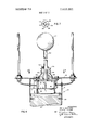
- FIG. 4 is an elevational view partly in section of the sensor transmitter unit using dynamic pressure sensing device for determining wind velocity and static barometric pressure;
- FIG. 5 is a partly sectional view taken along the line 5-5 of FIG. 4;
- FIG. 6 is an elevational view partly in section of the sensor transmitter unit modified to use strain gage sensors for determining wind velocity
- FIG. 7 is a sectional view taken along line 7-7 of FIG. 6 showing strain gages
- FIG. 8 is a functional block diagram of the sensor transmitter
- FIG. 9 is an electronic diagram of the signal conditioning system
- FIG. 10 is a diagrammatic view which illustrates the total alarm discrete pulse
- FIG. III is an electronic schematic view of the sensor transmitter
- FIG. 12 is a diagrammatic view of the relay transmission and receiver patterns of the S/T.
- FIG. 13 is a functional block diagram of the SH power system
- FIG. 14 is a view in front elevation of the home receiver.
- FIG. 15 is a sectional view in side elevation of the home receiver taken from the left side of FIG. l5.
- FIG. I shows a view of a receiver alarm 13 installed in a home.
- FIG. 3 illustrates a typical grid network incorporating sensor transmitters I. The grid array is established by a statistical analysis of recorded tornado tracks such as shown in Tech. Paper 020, Tornado Occurrances in US, US. Dept. of Commerce.
- Such analysis provides a predominate track direction 2 with respect to local latitude which is utilized to align the sensor transmitter grid network, Sensor transmitter spacing along a grid track 3 is determined by the nominal transmitter operating range that will assure reception by the next adjacent sensor transmitter along the same track and by the probability of storm detection desired.
- Cross track sensor transmitter spacing 4 is also determined by the probability of storm detection desired and by the requirement of providing adequate sensor density to give a true selection warning to the home alarm receivers while providing a quick determination of a wandering tornado not following the prevailing storm track impinging on the next closely spaced track. In any event, spacing i cannot be greater than two times the tornado detection radius of the sensor transmitter units.
- FIGS. 4 and 5 provides a detailed view of a sensor transmitter unit II that comprises a pressure sensor 5 that measures the pressure build up in chamber 6 resulting from the local winds with relation to the local static pressure as determined by the barometer pressure sensor 7.
- Chamber 6 is pressurized through a plurality of ports 8 to the ends of which are attached a flapper type check valve 9 allowing pressure build up in the sensing chamber 6.
- the entrance to these ports 8 incorporates baffles 10 to prevent rain and snow from flowing into the sensing chamber 6.
- the ports 8 also incorporate at their entrance a screen Ill attached by screws 12 to block foreign objects from entering. When the wind velocity from any direction impinges on any port 8, the pressure increases because of the wind velocity and unseats the check valve 9 thereby pressurizing chamber 6.
- transducer 13 This increase in pressure depresses the wind sensing bellows 5 which is attached to an electrical transducer 13 resulting in a change in the transducer 13 electrical output.
- This transducer change provides an output voltage that is proportional to the wind velocity being measured.
- the transducer is connected to the input of threshold amplifying device 75 to be later described.
- the local barometric pressure sensor 7 is also an electrical transducer and provides an output voltage that is proportional to the local statis pressure. It also is connected to the threshold amplifying device 75.
- FIG. 6 illustrates a modified sensor transmitter unit llA that also incorporates both pressure and wind velocity sensing features.
- This unit is comprised of an antenna system which includes a sensing whip antenna 26 incorporating a drag producing device 27 securely attached to a mounting bracket 28. The remaining four antennas l7, l8, l), 21) are securely attached to the ground plane 2.1 as shown in FIG. 5.
- a protective flexible boot 29 is securely attached to whip antenna as by clamp 30 and the housing Bill by a clamp 32.
- the housing 311 encloses all the components previously described for embodiment 1 shown in FlGS. 4 and 5, which is comprised of transceiver l4, barometric sensor 7, battery system l5 and threshold amplifying system 75.
- the housing 3t also has provisions for mounting to structure 23 by fasteners 24.
- FIG. '1 provides a closer look at the details of the sensor transmitter wind velocity sensing unit.
- antenna 26 is attached rigidly to mount 28 by a threaded sleeve attachment 33 to which antenna 26 is bonded at 34.
- Antenna 26 is pro vided with four resistance type strain gages 35, 36, 37, A view of the strain gage arrangement is illustrated in FIG. 7.
- These gages provide the wind velocity sensing network for the sensor transmitter unit llA by the variation of their resistance as the antenna 26 is strained by the bending force of the wind.
- the strain gages 35, 36, 37 and 38 detect the change in surface stresses of the antenna 26. These stresses are converted into electrical signals which are a direct correlation between the wind velocity and the resistance across the strain gages 35, 36, 37 and 38 outputs.
- FIGS. 4 and 5 are views taken showing the antenna array system installation. They illustrate the positions of the elements l6, 17, 18, t9 and 2t) in a vertical array.
- the driven element to is located in the center; all other elements are located in pairs diametrically opposed and at right angles to each other.
- the driven element and element T7 are aligned with the prevailing storm track.
- the antenna elements l7, l8, l9 and are mounted in coaxial connectors 39, 4t), 41 and 42.
- the antenna element coax connector assemblies are then installed on a metal ground plane 2]. as shown in FlG. 5. All elements are electrically insulated from the ground plane 21.
- the driven elements 26, of H68. 6 and to, of FlG. 4 shown in both S/T configurations are used to transmit and receive the RF alert signals from the grid system shown in FIG. 3.
- the other elements 17, l8, l9 and 24) are antenna parasites which are used to direct the alert transmissions to the adjacent track sensor transceivers and home receivers as shown in H6. 32 to be discussed later.
- All elements, in the array, are connected to the ground plane through 1F components.
- the driven elements to and 26 a connected to the transceiver l4 output which is, in turn, terminated at the ground plane 21.
- the parasitic elements 17, 2'23, 3) and 2t) are connected to RF coils i3, 44, 45 and 46, shown in FIG. ill, and to the output of the antenna logic 47 shown in P16. 8. The opposite ends of the coils are also terminated in antenna logic 47.
- FlG. 8 is a block diagram illustrating the flow of the three possible storm alert signals; alert from sensed storm signature 48, an RF alert signal from a long track alarm transmitter 49, and RF alert signal from a cross track transmitter of grid system 50.
- the alert signal from the storm signature sensors 35, 36, 37, 38 strain gages or the resulting signal from transducer 13, and the barometric pressure signal 7 are processed through a signal conditioning and amplifier system 511 and 75 to establish a total storm alert discrete 52.
- the RF signal alerts 49 and 5d are processed through receiver detectors 5?) to produce up track commands 54.
- the total alert discrete 52 enables both up track and cross track transmission of the alert signal.
- Both the alert signals 52 and 5d are provided to the transmitter logic 55 for enabling the transmitter 56 to operate in one of two modes.
- Mode l the storm present mode 57 or mode 2.
- Mode 1 operation provides FM transmission relay to both cross track and down tracl: RF receivers.
- Mode l logic provides a transmitter enabling signal 59, an antenna array switching signal (it), together with a modulator control signal oil to code the transmitter 56 from the modulator 95 with storm present tone s2 and transmit the alert both along track 63 and cross track at to S/T monitors and local home receivers along the alerted trackv Alert 63 is received as RF alert 49 in the adjacent S/T.
- Signal 64 is received as RF across line 5t).
- Mode 2 logic provides a transmitter enabling signal 65, an antenna switching signal 66, together with a modulator control signal 67 to code the transmitter 513 with storm alert present tone as and transmits the alert along track '63 only.
- FlG. 9 illustrates the electrical implementation of the sensor signal conditioning system 51 and threshold amplifier 75.
- the signal conditioning system 51 comprises a prcamplifying section 73 and a logic section 74 which is that part of the storm detection system which converts to electronic measures the wind velocity in the four strain gage bridge network 35, 36, 37 and 38.
- the strain gage output signals 69, 7t), 7t and 72 are processed through a preamplifying stage 73, a sensor logic gate 74 and a threshold amplifying device 75.
- the preamplifying stage 73 enhances the signal strength of the strain gage outputs 69, 70, 7t and 72 and directs them to the sensor logic input 76, 77, 78 and 79 at sensor logic gage 74 which sums the signals 76, 77, 78 and 79 in the resistor diode network to produce two control signals 80 and 81.
- These control signals 80 and 81 then drive the threshold amplifying device 75 which is biased to activate at an electrical level set for the critical wind velocity.
- the threshold amplifier is enabled through a transistor gate 82 which is controlled by barometric pressure signal 7 of the pressure transducer.
- the barometric pressure transistor gate 32 is activated by the strength of the signal generated by pressures critical for heavy storm conditions.
- the plenum chamber configuration output from transducer 13 is connected to input 80 of the threshold amplifier 75; 73 and 74 are not used in the plenum chamber configuration.
- the alert signal output is shaped to minimize false alarms and also to hold the alarm in for a minimum of time. As shown, when the discrete is up a time A 1 must be surpassed before the trigger level of the transmitter logic is reached.
- the system is switched to the transmitter mode 1 and remains there until the total discrete is down.
- Transmitter logic is reset when total alarm time is (T -At) +Az
- An implementation of the alert signal processing is shown in FlG. lit.
- the receiver 83 detects and amplifies radiated storm present RF relay alerts from either along track 63 or cross track s4 transmissions as shown in FIGS. 8 and 12.
- the RF signals 3 and 64 are processed in RF receiver 33 to produce demodulated keying signals 84 and as.
- the dynamic storm conditioner or sensor Sl processes the storm present condition signal and outputs a discrete signal 52.
- Both the demodulated RF key 84 and the storm present discrete 52 inputs OR element 85 resulting in an ORd output 9J1.
- Output 9t provides inputs to power switch 94 and to AND logic element 101.
- the resulting output 103 from power switch 94 enables transmitter 56 and modulator 95.
- RF rey 84 also provides an input to antenna logic switching element 1105 resulting in an output which drives the P. (reflectors) input to logic gate elements B02, 3106 and 107.
- the enable signal llllt will set gates M32, The and M7 to render antenna parasitic elements 18, i9 and 2t) reflectors with respect to driven antenna element lit) of the antenna array.
- the demodulated output 86 inputs both tone detector networks 37 anc
- the resulting output levels 39 and 92 are voltages resulting from the tone detectors processed and input 02' logic element 92.
- output 93 results.
- 93 is then processed in electronic integrator 104.
- the resulting output 109 drives electronic switch 97 and enables a second input to AND logic element 101.
- modulator 95 When output 109 is present at switch 97. modulator 95 is enabled and will provide a storm alert present modulation signal to transmitter 56.
- Power is provided through 112 to antenna logic elements 102, 103, 106 and 107.
- Power switch 113 supplies power to relay coil 114 causing the relay to switch the driven antenna 16 from the normally closed (NC) receiving condition 63 and 64 to the transmitting condition 99.
- Parasitic antenna element 18, 19 and 20 are switched to operating as reflectors when power switch 112 is activated. Element 17 does not switch.
- Alert discrete signal 52 from storm sensor component 51 inputs four logic switching elements; antenna logic switch element 105, OR element 85, modulator tone switching element 98 and also OR logic element 92.
- the resulting function of signal 52 present at element 105 is to turn the switch off, thus, making parasitic antenna elements 18, 19 and 20 directors.
- the resulting operation of switching element 98 when 52 is present is tum on, thus, changing the modulation frequency of 95.
- Signal 52 also inputs to OR logic element 92 providing operation as before; a) resulting in signal 93 which enables the modulator 95 through switch 97; b) switches the driven antenna element 16 to transmit through AND element 101, power switch 113 and relay 114 and c) enables antenna switching element 102, 103, 106 and 107 through power switch 112.
- the proposed system will use DC power, most of it in the RF stage during the transmitting period.
- the design approach is directed to implementing an automatic system, therefore, a self contained power source is needed that will remain active during the systems dormant state.
- the necessary use of batteries over an extended period of time will also require the utilization of a recharging system.
- the power system 15 shown in FIG. 13, utilizes a trickle charge from utility power to maintain the battery. Referring to FIG. 13, output (a) and (a) is used for low level RF and the logic circuits, while output (b) is used for high level switching and transmitting power.
- FIGS. 14 and 15 show a typical receiver alarm unit 1B that is comprised of power inverter 115 that is permanently attached to the housing 116 that contains all of the components of the receiver alarm unit. These components comprise the FM receiver 117 that is also attached to the housing 116 and is connected to antenna 118, the logic control circuit 119, that sends the alarm signal discrete to the Audiovisual alarm generator circuit 120, that will produce a loud alarm noise through speaker 121 and energize the indicator light 122.
- the receiver alarm is provided with a test button 123 that can be used to verify proper operation of the unit and the alarms from the Audiovisual generator 120. Power is supplied by the self contained rechargeable battery 124 which is maintained in a charged condition by the power inverter 115 through the power supply 125.
- the battery 124 will provide the required power to activate this alarm.
- Louvers 127 are provided to direct the sound from speaker 121 when the antenna 118 senses the radiation of a sensor transmitter 1 that is broadcasting an alarm that is directed to the FM receiver 117. The signal is detected by receiver 117 and provides an output to the logic control circuit 119. in the presence of an alarm signal-the logic control circuit 119 delivers an alarm discrete to the Audiovisual alarm generator 120 where an audible signal is produced and sent to s eaker 121 and a visual alarm signal is sent to the indicator lig t 122. The alarm signals 121 and 122 will remain on for a predetermined time that is incorporated in the time delay 128 of the receiver alarm. Upon completion of this delay 128, the receiver alarm unit will reset to its original state.
- An atmospheric disturbance warning system for detecting an approaching atmospheric disturbance comprising atmospheric condition sensors and transmitters responsive to said sensors which are located in a grid pattern, said transmitters transmitting an alarm signal by radio frequency to a receiver which detects the radio frequency signal and activates an alarm, said transmitter providing the signals for activating adjacent grid track monitors and home alarm receivers, the transmitter modulations being used to provide alarm signals through a first circuit to transmit signals in the path of the approaching disturbance termed mode (1) and a second circuit to transmit signals in and across the path of the approaching disturbance termed mode (2).
- the warning system as described in Claim 1 comprised of a logic section with a set of gates that determine the manner of transmission by selecting from the first circuit termed mode (1) storm present (storm activated) and the second circuit termed mode (2) storm alert present (radio frequency activated).
- the warning system of claim 1 in which the sensors and transmitters have the capability of providing a selection of radio frequency signals derived from frequency modulated carrier to alert home and other alarm receivers along the path of an approaching storm.
- the receiver section is made up of a radio frequency preamplifier, an intermediate frequency conversion strip and an audio signal detector, and the audio signal is then passed from the detector through a filter network which is tuned to output two separate coded audio alert signals into a logic and" gate.
- An atmospheric disturbance warning system for detecting an approaching atmospheric disturbance comprising atmospheric condition sensors and transmitters responsive to said sensors which are located in a grid pattern, said transmitters transmitting an alarm signal by radio frequency to a receiver which detects the radio frequency signal and activates an alarm, said alarm signals being transmitted in accordance with grid actuation logic which covers three parallel tracks centered at the initial detection point, said tracks paralleling the known local storm paths for the area, and adjacent parallel track monitors alerted by selected frequencies of the initial sensor transmitter monitor.
Abstract
A public warning system for alerting the public of natural disasters, such as tornadoes and other severe atmospheric disturbances, and having capabilities of giving general warning for civil defense for other emergencies. The system also has the capability to act as a sensor grid to obtain scientific atmospheric or weather or other geophysical data. A unique grid detection system is provided that predetermines and selects the area that will be affected and which residential areas will lie in the path of an approaching tornado. A selective warning of the affected residents is provided by sensor transmitters located in the grid at spaced grid points along the prevailing tornado''s track and to some safe distance along each side of the trace by signaling individual receiver alarm devices. The automatic alarm network is self-sustaining and is not dependent upon existing power distribution systems for its actuation.
Description
United States Patent [72] Inventors Pat 0. Bracken San Diego, Calif.; George H. Lane, St. Louis, Mo. [21] Appl. No. 756,819 ]22] Filed Sept. 3, 1968 [45] Patented Sept. 7, 1971 [73] Assignee Montech Incorporated Bridgeton, Mo.
[54] STORM WARNING SYSTEM 9 Claims, 15 Drawing Figs.
[52] US. Cl 340/224, 73/170 R, 325/64, 325/113, 340/182, 340/201 R, 340/421 [51] int. Cl ..G08b25 /Q0, 60% 19/00 [50] Field of Search 325/55, 64, 54, 51, 67, 113; 340/224, 420, 263, 421, 220, 220 D, 212,182, 201, 203,177;73/170 [56] References Cited UNITED STATES PATENTS 2,976,522 3/1961 Dowling 340/220 2,318,646 5/1943 White 340/201 X 2,402,688 6/ 1946 Skumick 340/212 2,444,106 6/1948 Miles 340/182 X Popular Science, 10 1961,pp. 102-103 Popu1ar Electronics, 4 1962, PD- 50 Primary Examiner-Robert L. Richardson AtIorney-Kingsland, Rogers, Ezell, Eilers & Robbins ABSTRACT: A public warning system for alerting the public of natural disasters, such as tornadoes and other severe atmospheric disturbances, and having capabilities of giving general warning for civil defense for other emergencies. The system also has the capability to act as a sensor grid to obtain scientific atmospheric or weather or other geophysical data. A unique grid detection system is provided that predeterrnines and selects the area that will be affected and which residential areas will lie in the path of an approaching tornado. A selec tive warning of the afiected residents is provided by sensor transmitters located in the grid at spaced grid points along the prevailing tomados track and to some safe distance along each side of the trace by signaling individual receiver alarm devices. The automatic alarm network is self-sustaining and is not dependent upon existing power distribution systems for its actuation.
PATENTEnsEP 7l97l 3Q603951 sum 1 OF 7 lNVENTORS o o a PAT o. BRACKEN 0 p O 0 GEORGE H. LANE O IOO 0 ATTORNEY6 PATENTEDSEP 7l97l 3,603,951
SHEET 2 BF 7 IO 9 8 ll 5 l3 I2 I I ll 22 Q I5 H I l I WT] 25 III! I 24 FIG. 4 23 FIG. 5
INVENTORS PAT O. BRACKEN Q l9 GEORGE H. LANE I BY 1 E i D ATTORNEYS PATENTED SEP 1 I871 FIG. 6
SHEET 3 [IF 7 23 INVENTORS PAT O. BRACKEN GEORGE H. LANE BY w W BMM A ATTORNEYS PATENTEU SEP 7 I971 SHEET 8 0F 7 A p Tm INVENTORS PAT O. BRACKEN GEORGE H. LANE w ll 20%;,
ZOE
ATTORNEYS STORM WARNING SYSTEM" SUMMARY OF THE INVENTION One of the most dreadful disasters that can occur is a tornado striking a thickly populated area without warning. An adequate warning of approaching tornadoes would enable residents to take precautions and seek shelter. Such a warning is needed by the public day and night, and would reduce the injury and loss of lives caused by the storms.
This invention comprises a plurality of sensor transmitters, hereinafter referred to as S/T, aligned in a grid network with sensors that detect, analyze and actuate fixed frequency transmitters, on a selective basis, providing a frequency modulation, hereinafter referred to as FM, carrier signal which is radiated to the individual alarm receivers which initiate the warning signal for the public.
This invention has the capability to provide for a tornado warning system using independent, automatic, self-sustaining sensor transmitter arranged in a grid pattern throughout the protected area and receiver alarms located in homes, businesses public buildings, aircraft installations and schools. The receiver alarms are activated by the S/T unit as a tornado penetrates the protected area. Although this invention is described for purpose of example as a tornado warning system, it will be apparent that it can be used to detect other atmospheric conditions, to collect atmospheric data, including temperature, humidity, wind velocity, barometric pressure, cloud cover, radiation, and the like, and can be used as a civil defense warning system.
The primary objects of the invention are to provide a unique grid detection system that predetermines and selects the area that will be affected and which residential areas will lie in the path of an approaching tornado or other atmospheric disturbance; to provide the selective warning of the affected residents by sensor transmitters located in a grid along the prevailing tornados track, and to some safe distance along each side of said track by alerting individual receiver alarm devices; to provide a self-sustaining, automatic alarm network that is not dependent on existing power distribution systems for its actuation; and also provide a clear unmistakable warn ing, day or night, for tornadoes detected along these prevailing storm tracks as determined by the grid network.
Other objects and advantages of the invention will become apparent from the following detailed description and will be otherwise apparent to those skilled in the art. For the purpose of illustration of this invention, there is shown in the accompanying drawings a preferred embodiment thereof. It is to be understood that these drawings are for the purpose of example only and that the invention is not limited thereto.
In the drawings:
FIG. I is a pictorial view of an area incorporating the invention;
FIG. 2 is a pictorial view of a receiver alarm installed in a home;
FIG. 3 is a schematic view of the grid detection system arrangement;
FIG. 4 is an elevational view partly in section of the sensor transmitter unit using dynamic pressure sensing device for determining wind velocity and static barometric pressure;
FIG. 5 is a partly sectional view taken along the line 5-5 of FIG. 4;
FIG. 6 is an elevational view partly in section of the sensor transmitter unit modified to use strain gage sensors for determining wind velocity;
FIG. 7 is a sectional view taken along line 7-7 of FIG. 6 showing strain gages;
FIG. 8 is a functional block diagram of the sensor transmitter;
FIG. 9 is an electronic diagram of the signal conditioning system;
FIG. 10 is a diagrammatic view which illustrates the total alarm discrete pulse;
FIG. III is an electronic schematic view of the sensor transmitter,
FIG. 12 is a diagrammatic view of the relay transmission and receiver patterns of the S/T;
FIG. 13 is a functional block diagram of the SH power system;
FIG. 14 is a view in front elevation of the home receiver; and
FIG. 15 is a sectional view in side elevation of the home receiver taken from the left side of FIG. l5.
This invention is embodied in the installation of a plurality of sensor transmitters l and home alarm receivers 18 situated in a unique network covering a specific, preselected area, illustrated by FIG. I, which will, after detecting a tornado, pro vide a selective warning to home receivers of the path of the oncoming tornado. FIG. 2 shows a view ofa receiver alarm 13 installed in a home. FIG. 3 illustrates a typical grid network incorporating sensor transmitters I. The grid array is established by a statistical analysis of recorded tornado tracks such as shown in Tech. Paper 020, Tornado Occurrances in US, US. Dept. of Commerce. Such analysis provides a predominate track direction 2 with respect to local latitude which is utilized to align the sensor transmitter grid network, Sensor transmitter spacing along a grid track 3 is determined by the nominal transmitter operating range that will assure reception by the next adjacent sensor transmitter along the same track and by the probability of storm detection desired.
Cross track sensor transmitter spacing 4 is also determined by the probability of storm detection desired and by the requirement of providing adequate sensor density to give a true selection warning to the home alarm receivers while providing a quick determination of a wandering tornado not following the prevailing storm track impinging on the next closely spaced track. In any event, spacing i cannot be greater than two times the tornado detection radius of the sensor transmitter units.
FIGS. 4 and 5 provides a detailed view of a sensor transmitter unit II that comprises a pressure sensor 5 that measures the pressure build up in chamber 6 resulting from the local winds with relation to the local static pressure as determined by the barometer pressure sensor 7. Chamber 6 is pressurized through a plurality of ports 8 to the ends of which are attached a flapper type check valve 9 allowing pressure build up in the sensing chamber 6. The entrance to these ports 8 incorporates baffles 10 to prevent rain and snow from flowing into the sensing chamber 6. The ports 8 also incorporate at their entrance a screen Ill attached by screws 12 to block foreign objects from entering. When the wind velocity from any direction impinges on any port 8, the pressure increases because of the wind velocity and unseats the check valve 9 thereby pressurizing chamber 6. This increase in pressure depresses the wind sensing bellows 5 which is attached to an electrical transducer 13 resulting in a change in the transducer 13 electrical output. This transducer change provides an output voltage that is proportional to the wind velocity being measured. The transducer is connected to the input of threshold amplifying device 75 to be later described. The local barometric pressure sensor 7 is also an electrical transducer and provides an output voltage that is proportional to the local statis pressure. It also is connected to the threshold amplifying device 75. When the critical combination of local pressure and wind velocity indication are present at the input of transceiver M is broadcasts a fixed frequency using the quarter wave antenna array system 16, l7, l8, W, 20 attached to the ground plane 21, which provides directional signal propagation. This system derives its power from a battery power system 15. All of the components of the sensor transmitter are enclosed within a housing 22 which has provisions for attachment to a rigid support post 23 by fasteners 24. An exter nal power source is connected to terminals 25 which supply external power to the batterys system 115. FIG. 6 illustrates a modified sensor transmitter unit llA that also incorporates both pressure and wind velocity sensing features. This unit is comprised of an antenna system which includes a sensing whip antenna 26 incorporating a drag producing device 27 securely attached to a mounting bracket 28. The remaining four antennas l7, l8, l), 21) are securely attached to the ground plane 2.1 as shown in FIG. 5. A protective flexible boot 29 is securely attached to whip antenna as by clamp 30 and the housing Bill by a clamp 32. The housing 311 encloses all the components previously described for embodiment 1 shown in FlGS. 4 and 5, which is comprised of transceiver l4, barometric sensor 7, battery system l5 and threshold amplifying system 75. The housing 3t also has provisions for mounting to structure 23 by fasteners 24.
FIG. '1 provides a closer look at the details of the sensor transmitter wind velocity sensing unit. In H6. 6 antenna 26 is attached rigidly to mount 28 by a threaded sleeve attachment 33 to which antenna 26 is bonded at 34. Antenna 26 is pro vided with four resistance type strain gages 35, 36, 37, A view of the strain gage arrangement is illustrated in FIG. 7. These gages provide the wind velocity sensing network for the sensor transmitter unit llA by the variation of their resistance as the antenna 26 is strained by the bending force of the wind. When the antenna is deflected as the result of wind impinging on the antenna 26 and the drag sphere 27, the strain gages 35, 36, 37 and 38 detect the change in surface stresses of the antenna 26. These stresses are converted into electrical signals which are a direct correlation between the wind velocity and the resistance across the strain gages 35, 36, 37 and 38 outputs.
FIGS. 4 and 5 are views taken showing the antenna array system installation. They illustrate the positions of the elements l6, 17, 18, t9 and 2t) in a vertical array. The driven element to is located in the center; all other elements are located in pairs diametrically opposed and at right angles to each other. The driven element and element T7 are aligned with the prevailing storm track. The antenna elements l7, l8, l9 and are mounted in coaxial connectors 39, 4t), 41 and 42. The antenna element coax connector assemblies are then installed on a metal ground plane 2]. as shown in FlG. 5. All elements are electrically insulated from the ground plane 21.
The driven elements 26, of H68. 6 and to, of FlG. 4 shown in both S/T configurations are used to transmit and receive the RF alert signals from the grid system shown in FIG. 3. The other elements 17, l8, l9 and 24) are antenna parasites which are used to direct the alert transmissions to the adjacent track sensor transceivers and home receivers as shown in H6. 32 to be discussed later.
All elements, in the array, are connected to the ground plane through 1F components. The driven elements to and 26 a connected to the transceiver l4 output which is, in turn, terminated at the ground plane 21. The parasitic elements 17, 2'23, 3) and 2t) are connected to RF coils i3, 44, 45 and 46, shown in FIG. ill, and to the output of the antenna logic 47 shown in P16. 8. The opposite ends of the coils are also terminated in antenna logic 47.
FlG. 8 is a block diagram illustrating the flow of the three possible storm alert signals; alert from sensed storm signature 48, an RF alert signal from a long track alarm transmitter 49, and RF alert signal from a cross track transmitter of grid system 50.
The alert signal from the storm signature sensors 35, 36, 37, 38 strain gages or the resulting signal from transducer 13, and the barometric pressure signal 7 are processed through a signal conditioning and amplifier system 511 and 75 to establish a total storm alert discrete 52. The RF signal alerts 49 and 5d are processed through receiver detectors 5?) to produce up track commands 54. The total alert discrete 52 enables both up track and cross track transmission of the alert signal.
Both the alert signals 52 and 5d are provided to the transmitter logic 55 for enabling the transmitter 56 to operate in one of two modes. Mode l, the storm present mode 57 or mode 2. storm alert present mode 58. Mode 1 operation provides FM transmission relay to both cross track and down tracl: RF receivers. Mode l logic provides a transmitter enabling signal 59, an antenna array switching signal (it), together with a modulator control signal oil to code the transmitter 56 from the modulator 95 with storm present tone s2 and transmit the alert both along track 63 and cross track at to S/T monitors and local home receivers along the alerted trackv Alert 63 is received as RF alert 49 in the adjacent S/T. Signal 64 is received as RF across line 5t).
FlG. 9 illustrates the electrical implementation of the sensor signal conditioning system 51 and threshold amplifier 75. The signal conditioning system 51 comprises a prcamplifying section 73 and a logic section 74 which is that part of the storm detection system which converts to electronic measures the wind velocity in the four strain gage bridge network 35, 36, 37 and 38. The strain gage output signals 69, 7t), 7t and 72 are processed through a preamplifying stage 73, a sensor logic gate 74 and a threshold amplifying device 75.
The preamplifying stage 73 enhances the signal strength of the strain gage outputs 69, 70, 7t and 72 and directs them to the sensor logic input 76, 77, 78 and 79 at sensor logic gage 74 which sums the signals 76, 77, 78 and 79 in the resistor diode network to produce two control signals 80 and 81. These control signals 80 and 81 then drive the threshold amplifying device 75 which is biased to activate at an electrical level set for the critical wind velocity. The threshold amplifier is enabled through a transistor gate 82 which is controlled by barometric pressure signal 7 of the pressure transducer. The barometric pressure transistor gate 32 is activated by the strength of the signal generated by pressures critical for heavy storm conditions. The plenum chamber configuration output from transducer 13 is connected to input 80 of the threshold amplifier 75; 73 and 74 are not used in the plenum chamber configuration.
When both wind sensor and static pressure signals have exceeded their respective threshold levels, the total alert discrete 52 is produced. An illustration of the total alcrt discrete 52 is shown in FlG. lb.
The alert signal output is shaped to minimize false alarms and also to hold the alarm in for a minimum of time. As shown, when the discrete is up a time A 1 must be surpassed before the trigger level of the transmitter logic is reached.
Once that level is reached, the system is switched to the transmitter mode 1 and remains there until the total discrete is down. Transmitter logic is reset when total alarm time is (T -At) +Az An implementation of the alert signal processing is shown in FlG. lit. The receiver 83 detects and amplifies radiated storm present RF relay alerts from either along track 63 or cross track s4 transmissions as shown in FIGS. 8 and 12. The RF signals 3 and 64 are processed in RF receiver 33 to produce demodulated keying signals 84 and as.
The dynamic storm conditioner or sensor Sl processes the storm present condition signal and outputs a discrete signal 52. Both the demodulated RF key 84 and the storm present discrete 52 inputs OR element 85 resulting in an ORd output 9J1. Output 9t provides inputs to power switch 94 and to AND logic element 101. The resulting output 103 from power switch 94 enables transmitter 56 and modulator 95. RF rey 84 also provides an input to antenna logic switching element 1105 resulting in an output which drives the P. (reflectors) input to logic gate elements B02, 3106 and 107. The enable signal llllt will set gates M32, The and M7 to render antenna parasitic elements 18, i9 and 2t) reflectors with respect to driven antenna element lit) of the antenna array.
The demodulated output 86 inputs both tone detector networks 37 anc The resulting output levels 39 and 92 are voltages resulting from the tone detectors processed and input 02' logic element 92. When the threshold level of 92 is reached, output 93 results. Thus, 93 is then processed in electronic integrator 104. The resulting output 109 drives electronic switch 97 and enables a second input to AND logic element 101.
When output 109 is present at switch 97. modulator 95 is enabled and will provide a storm alert present modulation signal to transmitter 56.
When both enabling signals 109 and 91 are present at logic element 101 an out signal 111 results. This signal 111 drives power switches 112 and 113.
Power is provided through 112 to antenna logic elements 102, 103, 106 and 107. Power switch 113 supplies power to relay coil 114 causing the relay to switch the driven antenna 16 from the normally closed (NC) receiving condition 63 and 64 to the transmitting condition 99. Parasitic antenna element 18, 19 and 20 are switched to operating as reflectors when power switch 112 is activated. Element 17 does not switch.
The system remains in the transmitting mode 63 as shown in FIG. 12, until integrator 104 output 109 drops below the AND logic element 101 threshold level, at this point, the system reverts to receiving mode 63, 64 and 64a shown in FIG. 12. Alert discrete signal 52 from storm sensor component 51 inputs four logic switching elements; antenna logic switch element 105, OR element 85, modulator tone switching element 98 and also OR logic element 92.
The resulting function of signal 52 present at element 105 is to turn the switch off, thus, making parasitic antenna elements 18, 19 and 20 directors. The resulting operation of switching element 98 when 52 is present is tum on, thus, changing the modulation frequency of 95.
The resulting transmission pattern shown in FIG. 12, 63, 64 and 64a is produced.
The proposed system will use DC power, most of it in the RF stage during the transmitting period. The design approach is directed to implementing an automatic system, therefore, a self contained power source is needed that will remain active during the systems dormant state. The necessary use of batteries over an extended period of time will also require the utilization of a recharging system. The power system 15 shown in FIG. 13, utilizes a trickle charge from utility power to maintain the battery. Referring to FIG. 13, output (a) and (a) is used for low level RF and the logic circuits, while output (b) is used for high level switching and transmitting power.
FIGS. 14 and 15 show a typical receiver alarm unit 1B that is comprised of power inverter 115 that is permanently attached to the housing 116 that contains all of the components of the receiver alarm unit. These components comprise the FM receiver 117 that is also attached to the housing 116 and is connected to antenna 118, the logic control circuit 119, that sends the alarm signal discrete to the Audiovisual alarm generator circuit 120, that will produce a loud alarm noise through speaker 121 and energize the indicator light 122. The receiver alarm is provided with a test button 123 that can be used to verify proper operation of the unit and the alarms from the Audiovisual generator 120. Power is supplied by the self contained rechargeable battery 124 which is maintained in a charged condition by the power inverter 115 through the power supply 125. In the event that power is not available from the standard wall outlet 126, the battery 124 will provide the required power to activate this alarm. Louvers 127 are provided to direct the sound from speaker 121 when the antenna 118 senses the radiation of a sensor transmitter 1 that is broadcasting an alarm that is directed to the FM receiver 117. The signal is detected by receiver 117 and provides an output to the logic control circuit 119. in the presence of an alarm signal-the logic control circuit 119 delivers an alarm discrete to the Audiovisual alarm generator 120 where an audible signal is produced and sent to s eaker 121 and a visual alarm signal is sent to the indicator lig t 122. The alarm signals 121 and 122 will remain on for a predetermined time that is incorporated in the time delay 128 of the receiver alarm. Upon completion of this delay 128, the receiver alarm unit will reset to its original state.
Various changes and modifications may be made within this invention as will be readily apparent to those skilled in the art. Such changes and modifications are within the scope and teaching of this invention as defined by the claims appended hereto.
What is claimed is:
1. An atmospheric disturbance warning system for detecting an approaching atmospheric disturbance comprising atmospheric condition sensors and transmitters responsive to said sensors which are located in a grid pattern, said transmitters transmitting an alarm signal by radio frequency to a receiver which detects the radio frequency signal and activates an alarm, said transmitter providing the signals for activating adjacent grid track monitors and home alarm receivers, the transmitter modulations being used to provide alarm signals through a first circuit to transmit signals in the path of the approaching disturbance termed mode (1) and a second circuit to transmit signals in and across the path of the approaching disturbance termed mode (2).
2. The warning system as described in Claim 1 comprised of a logic section with a set of gates that determine the manner of transmission by selecting from the first circuit termed mode (1) storm present (storm activated) and the second circuit termed mode (2) storm alert present (radio frequency activated).
3. The logic section as described in claim 4 whereunder the mode (1) storm present (storm activated) condition, the transmitter will broadcast downline and crossline alarm signals to adjacent monitors.
4. The logic section as described in claim 4 whereunder mode (2) storm alert present (radio frequency activated) con ditions the adjacent monitors will receive the transmitted alert and retransmit it down line.
5. The warning system of claim 1 in which the sensors and transmitters have the capability of providing a selection of radio frequency signals derived from frequency modulated carrier to alert home and other alarm receivers along the path of an approaching storm.
6. The warning system as described in claim 5 in which the said receiver alarm is self sustaining through a trickle charge to recharge batteries and consists of a logic control and an alarm generator, the said receiver section detecting the monitor alert signals and converting them into audio level signals.
7. The warning system of claim 1 in which the receiver section is made up of a radio frequency preamplifier, an intermediate frequency conversion strip and an audio signal detector, and the audio signal is then passed from the detector through a filter network which is tuned to output two separate coded audio alert signals into a logic and" gate.
8. The receiver alarm as described in claim 7 in which when the two signals are present the and gate outputs a discrete to turn on an alarm generator, the alarm discrete also triggering a time delay latching circuit that maintains the alarm discrete for a finite time after the alert condition has been passed.
9. An atmospheric disturbance warning system for detecting an approaching atmospheric disturbance comprising atmospheric condition sensors and transmitters responsive to said sensors which are located in a grid pattern, said transmitters transmitting an alarm signal by radio frequency to a receiver which detects the radio frequency signal and activates an alarm, said alarm signals being transmitted in accordance with grid actuation logic which covers three parallel tracks centered at the initial detection point, said tracks paralleling the known local storm paths for the area, and adjacent parallel track monitors alerted by selected frequencies of the initial sensor transmitter monitor.
Claims (9)
1. An atmospheric disturbance warning system for detecting an approaching atmospheric disturbance comprising atmospheric condition sensors and transmitters responsive to said sensors which are located in a grid pattern, said transmitters transmitting an alarm signal by radio frequency to a receiver which detects the radio frequency signal and activates an alarm, said transmitter providing the signals for activating adjacent grid track monitors and home alarm receivers, the transmitter modulations being used to provide alarm signals through a first circuit to transmit signals in the path of the approaching disturbance termed mode (1) and a second circuit to transmit signals in and across the path of the approaching disturbance termed mode (2).
2. ThE warning system as described in Claim 1 comprised of a logic section with a set of gates that determine the manner of transmission by selecting from the first circuit termed mode (1) storm present (storm activated) and the second circuit termed mode (2) storm alert present (radio frequency activated).
3. The logic section as described in claim 4 whereunder the mode (1) storm present (storm activated) condition, the transmitter will broadcast downline and crossline alarm signals to adjacent monitors.
4. The logic section as described in claim 4 whereunder mode (2) storm alert present (radio frequency activated) conditions the adjacent monitors will receive the transmitted alert and retransmit it down line.
5. The warning system of claim 1 in which the sensors and transmitters have the capability of providing a selection of radio frequency signals derived from frequency modulated carrier to alert home and other alarm receivers along the path of an approaching storm.
6. The warning system as described in claim 5 in which the said receiver alarm is self sustaining through a trickle charge to recharge batteries and consists of a logic control and an alarm generator, the said receiver section detecting the monitor alert signals and converting them into audio level signals.
7. The warning system of claim 1 in which the receiver section is made up of a radio frequency preamplifier, an intermediate frequency conversion strip and an audio signal detector, and the audio signal is then passed from the detector through a filter network which is tuned to output two separate coded audio alert signals into a logic ''''and'''' gate.
8. The receiver alarm as described in claim 7 in which when the two signals are present the ''''and'''' gate outputs a discrete to turn on an alarm generator, the alarm discrete also triggering a time delay latching circuit that maintains the alarm discrete for a finite time after the alert condition has been passed.
9. An atmospheric disturbance warning system for detecting an approaching atmospheric disturbance comprising atmospheric condition sensors and transmitters responsive to said sensors which are located in a grid pattern, said transmitters transmitting an alarm signal by radio frequency to a receiver which detects the radio frequency signal and activates an alarm, said alarm signals being transmitted in accordance with grid actuation logic which covers three parallel tracks centered at the initial detection point, said tracks paralleling the known local storm paths for the area, and adjacent parallel track monitors alerted by selected frequencies of the initial sensor transmitter monitor.
Applications Claiming Priority (1)
| Application Number | Priority Date | Filing Date | Title |
|---|---|---|---|
| US75681968A | 1968-09-03 | 1968-09-03 |
Publications (1)
| Publication Number | Publication Date |
|---|---|
| US3603951A true US3603951A (en) | 1971-09-07 |
Family
ID=25045194
Family Applications (1)
| Application Number | Title | Priority Date | Filing Date |
|---|---|---|---|
| US756819A Expired - Lifetime US3603951A (en) | 1968-09-03 | 1968-09-03 | Storm warning system |
Country Status (1)
| Country | Link |
|---|---|
| US (1) | US3603951A (en) |
Cited By (137)
| Publication number | Priority date | Publication date | Assignee | Title |
|---|---|---|---|---|
| US3848193A (en) * | 1972-12-15 | 1974-11-12 | Gautney & Jones Communications | Nationwide system for selectively distributing information |
| US4115732A (en) * | 1976-10-14 | 1978-09-19 | The University Of Arizona Foundation | Detection system for lightning |
| US4396149A (en) * | 1980-12-30 | 1983-08-02 | Energy Management Corporation | Irrigation control system |
| US5140523A (en) * | 1989-09-05 | 1992-08-18 | Ktaadn, Inc. | Neural network for predicting lightning |
| US5291208A (en) * | 1992-04-30 | 1994-03-01 | Rabun Labs, Inc. | Incipient lightning detection and device protection |
| US5435178A (en) * | 1990-08-06 | 1995-07-25 | G. D. Engineering Associates Limited | Blast gauge wherein four pressure sensors are positioned in a tetrahedral configuration on the surface of a sphere |
| US5521603A (en) * | 1992-04-30 | 1996-05-28 | Rabun Labs, Inc. | Incipient lightning detection and device protection |
| US5546800A (en) * | 1995-11-08 | 1996-08-20 | Daniel; Bernard | Early warning tornado detector |
| US5585558A (en) * | 1995-07-20 | 1996-12-17 | Prognosticating Scanners Llc | Catastrophic event forecasting system and method |
| US5612667A (en) * | 1995-07-05 | 1997-03-18 | Ford Motor Company | In-vehicle barometric pressure detection system |
| US6002748A (en) * | 1999-01-27 | 1999-12-14 | Leichner; James L. | Disaster alert by telephone system |
| US6076044A (en) * | 1997-02-13 | 2000-06-13 | Anthony Brown | Weather detector |
| WO2000059236A1 (en) * | 1999-03-26 | 2000-10-05 | Cell South, Inc. | Providing warning signals of graphic granularity |
| US6169487B1 (en) * | 1999-12-13 | 2001-01-02 | Robert B. Davis | Severe storm warning system |
| US6204761B1 (en) * | 1998-11-13 | 2001-03-20 | Jerome Vanderable | Weather alert system |
| US6255953B1 (en) * | 1999-06-14 | 2001-07-03 | Jerry Keith Barber | Tornado warning system |
| US6295001B1 (en) | 1999-06-14 | 2001-09-25 | Jerry Keith Barber | Tornado warning system |
| US6452492B1 (en) | 1996-12-05 | 2002-09-17 | Cable Alarm, Inc. | Emergency alert system |
| US6462665B1 (en) | 2000-05-16 | 2002-10-08 | Wheelock, Inc. | Method and apparatus for sending a weather condition alert |
| US6463273B1 (en) | 1999-05-11 | 2002-10-08 | J. Cameron Day | Wireless warning system |
| US6710715B2 (en) * | 2001-01-25 | 2004-03-23 | Douglas Arthur Deeds | Alarm system with integrated weather alert function |
| US20060005219A1 (en) * | 2004-07-02 | 2006-01-05 | Garry Owens | Standby television warning system |
| US20110025500A1 (en) * | 2000-03-24 | 2011-02-03 | Piccioni Robert L | Method and System for Situation Tracking and Notification |
| US20140055272A1 (en) * | 2012-08-24 | 2014-02-27 | Allan McCormick | User-Configurable Weather Warning Apparatus |
| US20140260596A1 (en) * | 2013-03-12 | 2014-09-18 | Subsidence, Inc. | Mechanical strain-based weather sensor |
| US9674711B2 (en) | 2013-11-06 | 2017-06-06 | At&T Intellectual Property I, L.P. | Surface-wave communications and methods thereof |
| US9685992B2 (en) | 2014-10-03 | 2017-06-20 | At&T Intellectual Property I, L.P. | Circuit panel network and methods thereof |
| US9705561B2 (en) | 2015-04-24 | 2017-07-11 | At&T Intellectual Property I, L.P. | Directional coupling device and methods for use therewith |
| US9705610B2 (en) | 2014-10-21 | 2017-07-11 | At&T Intellectual Property I, L.P. | Transmission device with impairment compensation and methods for use therewith |
| US9729197B2 (en) | 2015-10-01 | 2017-08-08 | At&T Intellectual Property I, L.P. | Method and apparatus for communicating network management traffic over a network |
| US9735833B2 (en) | 2015-07-31 | 2017-08-15 | At&T Intellectual Property I, L.P. | Method and apparatus for communications management in a neighborhood network |
| US9742462B2 (en) | 2014-12-04 | 2017-08-22 | At&T Intellectual Property I, L.P. | Transmission medium and communication interfaces and methods for use therewith |
| US9742521B2 (en) | 2014-11-20 | 2017-08-22 | At&T Intellectual Property I, L.P. | Transmission device with mode division multiplexing and methods for use therewith |
| US9748626B2 (en) | 2015-05-14 | 2017-08-29 | At&T Intellectual Property I, L.P. | Plurality of cables having different cross-sectional shapes which are bundled together to form a transmission medium |
| US9749053B2 (en) | 2015-07-23 | 2017-08-29 | At&T Intellectual Property I, L.P. | Node device, repeater and methods for use therewith |
| US9749013B2 (en) | 2015-03-17 | 2017-08-29 | At&T Intellectual Property I, L.P. | Method and apparatus for reducing attenuation of electromagnetic waves guided by a transmission medium |
| US9769128B2 (en) | 2015-09-28 | 2017-09-19 | At&T Intellectual Property I, L.P. | Method and apparatus for encryption of communications over a network |
| US9768833B2 (en) | 2014-09-15 | 2017-09-19 | At&T Intellectual Property I, L.P. | Method and apparatus for sensing a condition in a transmission medium of electromagnetic waves |
| US9769020B2 (en) | 2014-10-21 | 2017-09-19 | At&T Intellectual Property I, L.P. | Method and apparatus for responding to events affecting communications in a communication network |
| US9780834B2 (en) | 2014-10-21 | 2017-10-03 | At&T Intellectual Property I, L.P. | Method and apparatus for transmitting electromagnetic waves |
| US9787412B2 (en) | 2015-06-25 | 2017-10-10 | At&T Intellectual Property I, L.P. | Methods and apparatus for inducing a fundamental wave mode on a transmission medium |
| US9793954B2 (en) | 2015-04-28 | 2017-10-17 | At&T Intellectual Property I, L.P. | Magnetic coupling device and methods for use therewith |
| US9793955B2 (en) | 2015-04-24 | 2017-10-17 | At&T Intellectual Property I, Lp | Passive electrical coupling device and methods for use therewith |
| US9800327B2 (en) | 2014-11-20 | 2017-10-24 | At&T Intellectual Property I, L.P. | Apparatus for controlling operations of a communication device and methods thereof |
| US9820146B2 (en) | 2015-06-12 | 2017-11-14 | At&T Intellectual Property I, L.P. | Method and apparatus for authentication and identity management of communicating devices |
| US9838078B2 (en) | 2015-07-31 | 2017-12-05 | At&T Intellectual Property I, L.P. | Method and apparatus for exchanging communication signals |
| US9838896B1 (en) | 2016-12-09 | 2017-12-05 | At&T Intellectual Property I, L.P. | Method and apparatus for assessing network coverage |
| US9847850B2 (en) | 2014-10-14 | 2017-12-19 | At&T Intellectual Property I, L.P. | Method and apparatus for adjusting a mode of communication in a communication network |
| US9847566B2 (en) | 2015-07-14 | 2017-12-19 | At&T Intellectual Property I, L.P. | Method and apparatus for adjusting a field of a signal to mitigate interference |
| US9853342B2 (en) | 2015-07-14 | 2017-12-26 | At&T Intellectual Property I, L.P. | Dielectric transmission medium connector and methods for use therewith |
| US9860075B1 (en) | 2016-08-26 | 2018-01-02 | At&T Intellectual Property I, L.P. | Method and communication node for broadband distribution |
| US9865911B2 (en) | 2015-06-25 | 2018-01-09 | At&T Intellectual Property I, L.P. | Waveguide system for slot radiating first electromagnetic waves that are combined into a non-fundamental wave mode second electromagnetic wave on a transmission medium |
| US9866309B2 (en) | 2015-06-03 | 2018-01-09 | At&T Intellectual Property I, Lp | Host node device and methods for use therewith |
| US9866276B2 (en) | 2014-10-10 | 2018-01-09 | At&T Intellectual Property I, L.P. | Method and apparatus for arranging communication sessions in a communication system |
| US9871282B2 (en) | 2015-05-14 | 2018-01-16 | At&T Intellectual Property I, L.P. | At least one transmission medium having a dielectric surface that is covered at least in part by a second dielectric |
| US9871558B2 (en) | 2014-10-21 | 2018-01-16 | At&T Intellectual Property I, L.P. | Guided-wave transmission device and methods for use therewith |
| US9871283B2 (en) | 2015-07-23 | 2018-01-16 | At&T Intellectual Property I, Lp | Transmission medium having a dielectric core comprised of plural members connected by a ball and socket configuration |
| US9876570B2 (en) | 2015-02-20 | 2018-01-23 | At&T Intellectual Property I, Lp | Guided-wave transmission device with non-fundamental mode propagation and methods for use therewith |
| US9876264B2 (en) | 2015-10-02 | 2018-01-23 | At&T Intellectual Property I, Lp | Communication system, guided wave switch and methods for use therewith |
| US9882257B2 (en) | 2015-07-14 | 2018-01-30 | At&T Intellectual Property I, L.P. | Method and apparatus for launching a wave mode that mitigates interference |
| US9887447B2 (en) | 2015-05-14 | 2018-02-06 | At&T Intellectual Property I, L.P. | Transmission medium having multiple cores and methods for use therewith |
| US9893795B1 (en) | 2016-12-07 | 2018-02-13 | At&T Intellectual Property I, Lp | Method and repeater for broadband distribution |
| US9904535B2 (en) | 2015-09-14 | 2018-02-27 | At&T Intellectual Property I, L.P. | Method and apparatus for distributing software |
| US9906269B2 (en) | 2014-09-17 | 2018-02-27 | At&T Intellectual Property I, L.P. | Monitoring and mitigating conditions in a communication network |
| US9912382B2 (en) | 2015-06-03 | 2018-03-06 | At&T Intellectual Property I, Lp | Network termination and methods for use therewith |
| US9912027B2 (en) | 2015-07-23 | 2018-03-06 | At&T Intellectual Property I, L.P. | Method and apparatus for exchanging communication signals |
| US9912033B2 (en) | 2014-10-21 | 2018-03-06 | At&T Intellectual Property I, Lp | Guided wave coupler, coupling module and methods for use therewith |
| US9913139B2 (en) | 2015-06-09 | 2018-03-06 | At&T Intellectual Property I, L.P. | Signal fingerprinting for authentication of communicating devices |
| US9911020B1 (en) | 2016-12-08 | 2018-03-06 | At&T Intellectual Property I, L.P. | Method and apparatus for tracking via a radio frequency identification device |
| US9917341B2 (en) | 2015-05-27 | 2018-03-13 | At&T Intellectual Property I, L.P. | Apparatus and method for launching electromagnetic waves and for modifying radial dimensions of the propagating electromagnetic waves |
| US9929755B2 (en) | 2015-07-14 | 2018-03-27 | At&T Intellectual Property I, L.P. | Method and apparatus for coupling an antenna to a device |
| US9927517B1 (en) | 2016-12-06 | 2018-03-27 | At&T Intellectual Property I, L.P. | Apparatus and methods for sensing rainfall |
| US9948333B2 (en) | 2015-07-23 | 2018-04-17 | At&T Intellectual Property I, L.P. | Method and apparatus for wireless communications to mitigate interference |
| US9954286B2 (en) | 2014-10-21 | 2018-04-24 | At&T Intellectual Property I, L.P. | Guided-wave transmission device with non-fundamental mode propagation and methods for use therewith |
| US9967173B2 (en) | 2015-07-31 | 2018-05-08 | At&T Intellectual Property I, L.P. | Method and apparatus for authentication and identity management of communicating devices |
| US9973416B2 (en) | 2014-10-02 | 2018-05-15 | At&T Intellectual Property I, L.P. | Method and apparatus that provides fault tolerance in a communication network |
| US9973940B1 (en) | 2017-02-27 | 2018-05-15 | At&T Intellectual Property I, L.P. | Apparatus and methods for dynamic impedance matching of a guided wave launcher |
| US9998870B1 (en) | 2016-12-08 | 2018-06-12 | At&T Intellectual Property I, L.P. | Method and apparatus for proximity sensing |
| US9997819B2 (en) | 2015-06-09 | 2018-06-12 | At&T Intellectual Property I, L.P. | Transmission medium and method for facilitating propagation of electromagnetic waves via a core |
| US9999038B2 (en) | 2013-05-31 | 2018-06-12 | At&T Intellectual Property I, L.P. | Remote distributed antenna system |
| US10009067B2 (en) | 2014-12-04 | 2018-06-26 | At&T Intellectual Property I, L.P. | Method and apparatus for configuring a communication interface |
| US10020844B2 (en) | 2016-12-06 | 2018-07-10 | T&T Intellectual Property I, L.P. | Method and apparatus for broadcast communication via guided waves |
| US10027397B2 (en) | 2016-12-07 | 2018-07-17 | At&T Intellectual Property I, L.P. | Distributed antenna system and methods for use therewith |
| US10044409B2 (en) | 2015-07-14 | 2018-08-07 | At&T Intellectual Property I, L.P. | Transmission medium and methods for use therewith |
| US10051630B2 (en) | 2013-05-31 | 2018-08-14 | At&T Intellectual Property I, L.P. | Remote distributed antenna system |
| US10069185B2 (en) | 2015-06-25 | 2018-09-04 | At&T Intellectual Property I, L.P. | Methods and apparatus for inducing a non-fundamental wave mode on a transmission medium |
| US10069535B2 (en) | 2016-12-08 | 2018-09-04 | At&T Intellectual Property I, L.P. | Apparatus and methods for launching electromagnetic waves having a certain electric field structure |
| US10090594B2 (en) | 2016-11-23 | 2018-10-02 | At&T Intellectual Property I, L.P. | Antenna system having structural configurations for assembly |
| US10090606B2 (en) | 2015-07-15 | 2018-10-02 | At&T Intellectual Property I, L.P. | Antenna system with dielectric array and methods for use therewith |
| US10103422B2 (en) | 2016-12-08 | 2018-10-16 | At&T Intellectual Property I, L.P. | Method and apparatus for mounting network devices |
| US10135145B2 (en) | 2016-12-06 | 2018-11-20 | At&T Intellectual Property I, L.P. | Apparatus and methods for generating an electromagnetic wave along a transmission medium |
| US10139820B2 (en) | 2016-12-07 | 2018-11-27 | At&T Intellectual Property I, L.P. | Method and apparatus for deploying equipment of a communication system |
| US10148016B2 (en) | 2015-07-14 | 2018-12-04 | At&T Intellectual Property I, L.P. | Apparatus and methods for communicating utilizing an antenna array |
| US10168695B2 (en) | 2016-12-07 | 2019-01-01 | At&T Intellectual Property I, L.P. | Method and apparatus for controlling an unmanned aircraft |
| US10178445B2 (en) | 2016-11-23 | 2019-01-08 | At&T Intellectual Property I, L.P. | Methods, devices, and systems for load balancing between a plurality of waveguides |
| US10205655B2 (en) | 2015-07-14 | 2019-02-12 | At&T Intellectual Property I, L.P. | Apparatus and methods for communicating utilizing an antenna array and multiple communication paths |
| US10224634B2 (en) | 2016-11-03 | 2019-03-05 | At&T Intellectual Property I, L.P. | Methods and apparatus for adjusting an operational characteristic of an antenna |
| US10225025B2 (en) | 2016-11-03 | 2019-03-05 | At&T Intellectual Property I, L.P. | Method and apparatus for detecting a fault in a communication system |
| US10243784B2 (en) | 2014-11-20 | 2019-03-26 | At&T Intellectual Property I, L.P. | System for generating topology information and methods thereof |
| US10243270B2 (en) | 2016-12-07 | 2019-03-26 | At&T Intellectual Property I, L.P. | Beam adaptive multi-feed dielectric antenna system and methods for use therewith |
| US10264586B2 (en) | 2016-12-09 | 2019-04-16 | At&T Mobility Ii Llc | Cloud-based packet controller and methods for use therewith |
| US10291334B2 (en) | 2016-11-03 | 2019-05-14 | At&T Intellectual Property I, L.P. | System for detecting a fault in a communication system |
| US10298293B2 (en) | 2017-03-13 | 2019-05-21 | At&T Intellectual Property I, L.P. | Apparatus of communication utilizing wireless network devices |
| US10305190B2 (en) | 2016-12-01 | 2019-05-28 | At&T Intellectual Property I, L.P. | Reflecting dielectric antenna system and methods for use therewith |
| US10312567B2 (en) | 2016-10-26 | 2019-06-04 | At&T Intellectual Property I, L.P. | Launcher with planar strip antenna and methods for use therewith |
| US10326689B2 (en) | 2016-12-08 | 2019-06-18 | At&T Intellectual Property I, L.P. | Method and system for providing alternative communication paths |
| US10326494B2 (en) | 2016-12-06 | 2019-06-18 | At&T Intellectual Property I, L.P. | Apparatus for measurement de-embedding and methods for use therewith |
| US10340983B2 (en) | 2016-12-09 | 2019-07-02 | At&T Intellectual Property I, L.P. | Method and apparatus for surveying remote sites via guided wave communications |
| US10340601B2 (en) | 2016-11-23 | 2019-07-02 | At&T Intellectual Property I, L.P. | Multi-antenna system and methods for use therewith |
| US10340603B2 (en) | 2016-11-23 | 2019-07-02 | At&T Intellectual Property I, L.P. | Antenna system having shielded structural configurations for assembly |
| US10340573B2 (en) | 2016-10-26 | 2019-07-02 | At&T Intellectual Property I, L.P. | Launcher with cylindrical coupling device and methods for use therewith |
| US10355367B2 (en) | 2015-10-16 | 2019-07-16 | At&T Intellectual Property I, L.P. | Antenna structure for exchanging wireless signals |
| US10359749B2 (en) | 2016-12-07 | 2019-07-23 | At&T Intellectual Property I, L.P. | Method and apparatus for utilities management via guided wave communication |
| US10361489B2 (en) | 2016-12-01 | 2019-07-23 | At&T Intellectual Property I, L.P. | Dielectric dish antenna system and methods for use therewith |
| US10374316B2 (en) | 2016-10-21 | 2019-08-06 | At&T Intellectual Property I, L.P. | System and dielectric antenna with non-uniform dielectric |
| US10382976B2 (en) | 2016-12-06 | 2019-08-13 | At&T Intellectual Property I, L.P. | Method and apparatus for managing wireless communications based on communication paths and network device positions |
| US10389029B2 (en) | 2016-12-07 | 2019-08-20 | At&T Intellectual Property I, L.P. | Multi-feed dielectric antenna system with core selection and methods for use therewith |
| US10389037B2 (en) | 2016-12-08 | 2019-08-20 | At&T Intellectual Property I, L.P. | Apparatus and methods for selecting sections of an antenna array and use therewith |
| US10411356B2 (en) | 2016-12-08 | 2019-09-10 | At&T Intellectual Property I, L.P. | Apparatus and methods for selectively targeting communication devices with an antenna array |
| US10439675B2 (en) | 2016-12-06 | 2019-10-08 | At&T Intellectual Property I, L.P. | Method and apparatus for repeating guided wave communication signals |
| US10446936B2 (en) | 2016-12-07 | 2019-10-15 | At&T Intellectual Property I, L.P. | Multi-feed dielectric antenna system and methods for use therewith |
| US10498044B2 (en) | 2016-11-03 | 2019-12-03 | At&T Intellectual Property I, L.P. | Apparatus for configuring a surface of an antenna |
| US10530505B2 (en) | 2016-12-08 | 2020-01-07 | At&T Intellectual Property I, L.P. | Apparatus and methods for launching electromagnetic waves along a transmission medium |
| US10535928B2 (en) | 2016-11-23 | 2020-01-14 | At&T Intellectual Property I, L.P. | Antenna system and methods for use therewith |
| US10547348B2 (en) | 2016-12-07 | 2020-01-28 | At&T Intellectual Property I, L.P. | Method and apparatus for switching transmission mediums in a communication system |
| US10601494B2 (en) | 2016-12-08 | 2020-03-24 | At&T Intellectual Property I, L.P. | Dual-band communication device and method for use therewith |
| US10637149B2 (en) | 2016-12-06 | 2020-04-28 | At&T Intellectual Property I, L.P. | Injection molded dielectric antenna and methods for use therewith |
| US10650940B2 (en) | 2015-05-15 | 2020-05-12 | At&T Intellectual Property I, L.P. | Transmission medium having a conductive material and methods for use therewith |
| US10694379B2 (en) | 2016-12-06 | 2020-06-23 | At&T Intellectual Property I, L.P. | Waveguide system with device-based authentication and methods for use therewith |
| US10727599B2 (en) | 2016-12-06 | 2020-07-28 | At&T Intellectual Property I, L.P. | Launcher with slot antenna and methods for use therewith |
| US10755542B2 (en) | 2016-12-06 | 2020-08-25 | At&T Intellectual Property I, L.P. | Method and apparatus for surveillance via guided wave communication |
| US10777873B2 (en) | 2016-12-08 | 2020-09-15 | At&T Intellectual Property I, L.P. | Method and apparatus for mounting network devices |
| US10797781B2 (en) | 2015-06-03 | 2020-10-06 | At&T Intellectual Property I, L.P. | Client node device and methods for use therewith |
| US10811767B2 (en) | 2016-10-21 | 2020-10-20 | At&T Intellectual Property I, L.P. | System and dielectric antenna with convex dielectric radome |
| US10819035B2 (en) | 2016-12-06 | 2020-10-27 | At&T Intellectual Property I, L.P. | Launcher with helical antenna and methods for use therewith |
| US10916969B2 (en) | 2016-12-08 | 2021-02-09 | At&T Intellectual Property I, L.P. | Method and apparatus for providing power using an inductive coupling |
| US10938108B2 (en) | 2016-12-08 | 2021-03-02 | At&T Intellectual Property I, L.P. | Frequency selective multi-feed dielectric antenna system and methods for use therewith |
Citations (8)
| Publication number | Priority date | Publication date | Assignee | Title |
|---|---|---|---|---|
| US2318646A (en) * | 1940-08-01 | 1943-05-11 | Jud E White | Telemetric system |
| US2402688A (en) * | 1945-05-16 | 1946-06-25 | Us Government | Meteorological telemetering system |
| US2444106A (en) * | 1945-07-18 | 1948-06-29 | Bendix Aviat Corp | Automatic weather station |
| US2637841A (en) * | 1951-04-20 | 1953-05-05 | Us Army | Position finding of electrical disturbances |
| US2642564A (en) * | 1951-09-15 | 1953-06-16 | Leupold & Stevens Instr Inc | Radio reporting precipitation gauge |
| US2684474A (en) * | 1951-04-20 | 1954-07-20 | Us Army | Meteorological telemetering system |
| US2976522A (en) * | 1959-08-07 | 1961-03-21 | Arthur J Dowling | Severe storm and tornado warner |
| US3026501A (en) * | 1957-12-31 | 1962-03-20 | Rca Corp | Weather display and forecasting system |
-
1968
- 1968-09-03 US US756819A patent/US3603951A/en not_active Expired - Lifetime
Patent Citations (8)
| Publication number | Priority date | Publication date | Assignee | Title |
|---|---|---|---|---|
| US2318646A (en) * | 1940-08-01 | 1943-05-11 | Jud E White | Telemetric system |
| US2402688A (en) * | 1945-05-16 | 1946-06-25 | Us Government | Meteorological telemetering system |
| US2444106A (en) * | 1945-07-18 | 1948-06-29 | Bendix Aviat Corp | Automatic weather station |
| US2637841A (en) * | 1951-04-20 | 1953-05-05 | Us Army | Position finding of electrical disturbances |
| US2684474A (en) * | 1951-04-20 | 1954-07-20 | Us Army | Meteorological telemetering system |
| US2642564A (en) * | 1951-09-15 | 1953-06-16 | Leupold & Stevens Instr Inc | Radio reporting precipitation gauge |
| US3026501A (en) * | 1957-12-31 | 1962-03-20 | Rca Corp | Weather display and forecasting system |
| US2976522A (en) * | 1959-08-07 | 1961-03-21 | Arthur J Dowling | Severe storm and tornado warner |
Non-Patent Citations (2)
| Title |
|---|
| Popular Electronics, 04001962, pp. 50 * |
| Popular Science, 10001961, pp. 102 103 * |
Cited By (164)
| Publication number | Priority date | Publication date | Assignee | Title |
|---|---|---|---|---|
| US3848193A (en) * | 1972-12-15 | 1974-11-12 | Gautney & Jones Communications | Nationwide system for selectively distributing information |
| US4115732A (en) * | 1976-10-14 | 1978-09-19 | The University Of Arizona Foundation | Detection system for lightning |
| US4396149A (en) * | 1980-12-30 | 1983-08-02 | Energy Management Corporation | Irrigation control system |
| US5140523A (en) * | 1989-09-05 | 1992-08-18 | Ktaadn, Inc. | Neural network for predicting lightning |
| US5435178A (en) * | 1990-08-06 | 1995-07-25 | G. D. Engineering Associates Limited | Blast gauge wherein four pressure sensors are positioned in a tetrahedral configuration on the surface of a sphere |
| US5291208A (en) * | 1992-04-30 | 1994-03-01 | Rabun Labs, Inc. | Incipient lightning detection and device protection |
| US5521603A (en) * | 1992-04-30 | 1996-05-28 | Rabun Labs, Inc. | Incipient lightning detection and device protection |
| US5612667A (en) * | 1995-07-05 | 1997-03-18 | Ford Motor Company | In-vehicle barometric pressure detection system |
| US5585558A (en) * | 1995-07-20 | 1996-12-17 | Prognosticating Scanners Llc | Catastrophic event forecasting system and method |
| US5546800A (en) * | 1995-11-08 | 1996-08-20 | Daniel; Bernard | Early warning tornado detector |
| US6452492B1 (en) | 1996-12-05 | 2002-09-17 | Cable Alarm, Inc. | Emergency alert system |
| US6076044A (en) * | 1997-02-13 | 2000-06-13 | Anthony Brown | Weather detector |
| USRE45514E1 (en) | 1997-02-13 | 2015-05-12 | La Crosse Technology Ip Holdings, Llc | Severe weather detector and alarm |
| USRE43903E1 (en) * | 1997-02-13 | 2013-01-01 | Richmond Ip Holdings, Llc | Severe weather detector and alarm |
| US6597990B2 (en) | 1997-02-13 | 2003-07-22 | Anthony Brown | Severe weather detector and alarm |
| US6204761B1 (en) * | 1998-11-13 | 2001-03-20 | Jerome Vanderable | Weather alert system |
| US6002748A (en) * | 1999-01-27 | 1999-12-14 | Leichner; James L. | Disaster alert by telephone system |
| WO2000059236A1 (en) * | 1999-03-26 | 2000-10-05 | Cell South, Inc. | Providing warning signals of graphic granularity |
| US6463273B1 (en) | 1999-05-11 | 2002-10-08 | J. Cameron Day | Wireless warning system |
| US6295001B1 (en) | 1999-06-14 | 2001-09-25 | Jerry Keith Barber | Tornado warning system |
| US6255953B1 (en) * | 1999-06-14 | 2001-07-03 | Jerry Keith Barber | Tornado warning system |
| US6169487B1 (en) * | 1999-12-13 | 2001-01-02 | Robert B. Davis | Severe storm warning system |
| US20110025500A1 (en) * | 2000-03-24 | 2011-02-03 | Piccioni Robert L | Method and System for Situation Tracking and Notification |
| US20110050417A1 (en) * | 2000-03-24 | 2011-03-03 | Piccioni Robert L | Method and System for Situation Tracking and Notification |
| US6462665B1 (en) | 2000-05-16 | 2002-10-08 | Wheelock, Inc. | Method and apparatus for sending a weather condition alert |
| US6710715B2 (en) * | 2001-01-25 | 2004-03-23 | Douglas Arthur Deeds | Alarm system with integrated weather alert function |
| US20060005219A1 (en) * | 2004-07-02 | 2006-01-05 | Garry Owens | Standby television warning system |
| US10861319B2 (en) | 2012-08-24 | 2020-12-08 | La Crosse Technology Ltd. | User-configurable weather warning apparatus |
| US10204507B2 (en) * | 2012-08-24 | 2019-02-12 | La Crosse Technology, Ltd. | User-configurable weather warning apparatus |
| US20140055272A1 (en) * | 2012-08-24 | 2014-02-27 | Allan McCormick | User-Configurable Weather Warning Apparatus |
| US11443614B2 (en) | 2012-08-24 | 2022-09-13 | La Crosse Technology Ltd. | User-configurable weather warning apparatus |
| US11741826B2 (en) | 2012-08-24 | 2023-08-29 | La Crosse Technology Ltd. | User-configurable weather warning apparatus |
| US9846092B2 (en) * | 2013-03-12 | 2017-12-19 | Understory, Inc. | Mechanical strain-based weather sensor |
| US9958346B2 (en) * | 2013-03-12 | 2018-05-01 | Understory, Inc. | Mechanical strain-based weather sensor |
| US20180266903A1 (en) * | 2013-03-12 | 2018-09-20 | Understory, Inc. | Mechanical strain-based weather sensor |
| US10648877B2 (en) * | 2013-03-12 | 2020-05-12 | Understory, Inc. | Mechanical strain-based weather sensor |
| WO2014165173A1 (en) * | 2013-03-12 | 2014-10-09 | Subsidence, Inc. | Mechanical strain-based weather sensor |
| US20140260596A1 (en) * | 2013-03-12 | 2014-09-18 | Subsidence, Inc. | Mechanical strain-based weather sensor |
| US9999038B2 (en) | 2013-05-31 | 2018-06-12 | At&T Intellectual Property I, L.P. | Remote distributed antenna system |
| US10051630B2 (en) | 2013-05-31 | 2018-08-14 | At&T Intellectual Property I, L.P. | Remote distributed antenna system |
| US9674711B2 (en) | 2013-11-06 | 2017-06-06 | At&T Intellectual Property I, L.P. | Surface-wave communications and methods thereof |
| US9768833B2 (en) | 2014-09-15 | 2017-09-19 | At&T Intellectual Property I, L.P. | Method and apparatus for sensing a condition in a transmission medium of electromagnetic waves |
| US9906269B2 (en) | 2014-09-17 | 2018-02-27 | At&T Intellectual Property I, L.P. | Monitoring and mitigating conditions in a communication network |
| US10063280B2 (en) | 2014-09-17 | 2018-08-28 | At&T Intellectual Property I, L.P. | Monitoring and mitigating conditions in a communication network |
| US9973416B2 (en) | 2014-10-02 | 2018-05-15 | At&T Intellectual Property I, L.P. | Method and apparatus that provides fault tolerance in a communication network |
| US9685992B2 (en) | 2014-10-03 | 2017-06-20 | At&T Intellectual Property I, L.P. | Circuit panel network and methods thereof |
| US9866276B2 (en) | 2014-10-10 | 2018-01-09 | At&T Intellectual Property I, L.P. | Method and apparatus for arranging communication sessions in a communication system |
| US9847850B2 (en) | 2014-10-14 | 2017-12-19 | At&T Intellectual Property I, L.P. | Method and apparatus for adjusting a mode of communication in a communication network |
| US9769020B2 (en) | 2014-10-21 | 2017-09-19 | At&T Intellectual Property I, L.P. | Method and apparatus for responding to events affecting communications in a communication network |
| US9705610B2 (en) | 2014-10-21 | 2017-07-11 | At&T Intellectual Property I, L.P. | Transmission device with impairment compensation and methods for use therewith |
| US9960808B2 (en) | 2014-10-21 | 2018-05-01 | At&T Intellectual Property I, L.P. | Guided-wave transmission device and methods for use therewith |
| US9912033B2 (en) | 2014-10-21 | 2018-03-06 | At&T Intellectual Property I, Lp | Guided wave coupler, coupling module and methods for use therewith |
| US9876587B2 (en) | 2014-10-21 | 2018-01-23 | At&T Intellectual Property I, L.P. | Transmission device with impairment compensation and methods for use therewith |
| US9954286B2 (en) | 2014-10-21 | 2018-04-24 | At&T Intellectual Property I, L.P. | Guided-wave transmission device with non-fundamental mode propagation and methods for use therewith |
| US9871558B2 (en) | 2014-10-21 | 2018-01-16 | At&T Intellectual Property I, L.P. | Guided-wave transmission device and methods for use therewith |
| US9780834B2 (en) | 2014-10-21 | 2017-10-03 | At&T Intellectual Property I, L.P. | Method and apparatus for transmitting electromagnetic waves |
| US9749083B2 (en) | 2014-11-20 | 2017-08-29 | At&T Intellectual Property I, L.P. | Transmission device with mode division multiplexing and methods for use therewith |
| US9800327B2 (en) | 2014-11-20 | 2017-10-24 | At&T Intellectual Property I, L.P. | Apparatus for controlling operations of a communication device and methods thereof |
| US9742521B2 (en) | 2014-11-20 | 2017-08-22 | At&T Intellectual Property I, L.P. | Transmission device with mode division multiplexing and methods for use therewith |
| US10243784B2 (en) | 2014-11-20 | 2019-03-26 | At&T Intellectual Property I, L.P. | System for generating topology information and methods thereof |
| US9742462B2 (en) | 2014-12-04 | 2017-08-22 | At&T Intellectual Property I, L.P. | Transmission medium and communication interfaces and methods for use therewith |
| US10009067B2 (en) | 2014-12-04 | 2018-06-26 | At&T Intellectual Property I, L.P. | Method and apparatus for configuring a communication interface |
| US9876570B2 (en) | 2015-02-20 | 2018-01-23 | At&T Intellectual Property I, Lp | Guided-wave transmission device with non-fundamental mode propagation and methods for use therewith |
| US9876571B2 (en) | 2015-02-20 | 2018-01-23 | At&T Intellectual Property I, Lp | Guided-wave transmission device with non-fundamental mode propagation and methods for use therewith |
| US9749013B2 (en) | 2015-03-17 | 2017-08-29 | At&T Intellectual Property I, L.P. | Method and apparatus for reducing attenuation of electromagnetic waves guided by a transmission medium |
| US9831912B2 (en) | 2015-04-24 | 2017-11-28 | At&T Intellectual Property I, Lp | Directional coupling device and methods for use therewith |
| US10224981B2 (en) | 2015-04-24 | 2019-03-05 | At&T Intellectual Property I, Lp | Passive electrical coupling device and methods for use therewith |
| US9793955B2 (en) | 2015-04-24 | 2017-10-17 | At&T Intellectual Property I, Lp | Passive electrical coupling device and methods for use therewith |
| US9705561B2 (en) | 2015-04-24 | 2017-07-11 | At&T Intellectual Property I, L.P. | Directional coupling device and methods for use therewith |
| US9793954B2 (en) | 2015-04-28 | 2017-10-17 | At&T Intellectual Property I, L.P. | Magnetic coupling device and methods for use therewith |
| US9871282B2 (en) | 2015-05-14 | 2018-01-16 | At&T Intellectual Property I, L.P. | At least one transmission medium having a dielectric surface that is covered at least in part by a second dielectric |
| US9887447B2 (en) | 2015-05-14 | 2018-02-06 | At&T Intellectual Property I, L.P. | Transmission medium having multiple cores and methods for use therewith |
| US9748626B2 (en) | 2015-05-14 | 2017-08-29 | At&T Intellectual Property I, L.P. | Plurality of cables having different cross-sectional shapes which are bundled together to form a transmission medium |
| US10650940B2 (en) | 2015-05-15 | 2020-05-12 | At&T Intellectual Property I, L.P. | Transmission medium having a conductive material and methods for use therewith |
| US9917341B2 (en) | 2015-05-27 | 2018-03-13 | At&T Intellectual Property I, L.P. | Apparatus and method for launching electromagnetic waves and for modifying radial dimensions of the propagating electromagnetic waves |
| US9912381B2 (en) | 2015-06-03 | 2018-03-06 | At&T Intellectual Property I, Lp | Network termination and methods for use therewith |
| US10050697B2 (en) | 2015-06-03 | 2018-08-14 | At&T Intellectual Property I, L.P. | Host node device and methods for use therewith |
| US9912382B2 (en) | 2015-06-03 | 2018-03-06 | At&T Intellectual Property I, Lp | Network termination and methods for use therewith |
| US10812174B2 (en) | 2015-06-03 | 2020-10-20 | At&T Intellectual Property I, L.P. | Client node device and methods for use therewith |
| US9967002B2 (en) | 2015-06-03 | 2018-05-08 | At&T Intellectual I, Lp | Network termination and methods for use therewith |
| US9866309B2 (en) | 2015-06-03 | 2018-01-09 | At&T Intellectual Property I, Lp | Host node device and methods for use therewith |
| US9935703B2 (en) | 2015-06-03 | 2018-04-03 | At&T Intellectual Property I, L.P. | Host node device and methods for use therewith |
| US10797781B2 (en) | 2015-06-03 | 2020-10-06 | At&T Intellectual Property I, L.P. | Client node device and methods for use therewith |
| US9913139B2 (en) | 2015-06-09 | 2018-03-06 | At&T Intellectual Property I, L.P. | Signal fingerprinting for authentication of communicating devices |
| US9997819B2 (en) | 2015-06-09 | 2018-06-12 | At&T Intellectual Property I, L.P. | Transmission medium and method for facilitating propagation of electromagnetic waves via a core |
| US9820146B2 (en) | 2015-06-12 | 2017-11-14 | At&T Intellectual Property I, L.P. | Method and apparatus for authentication and identity management of communicating devices |
| US10069185B2 (en) | 2015-06-25 | 2018-09-04 | At&T Intellectual Property I, L.P. | Methods and apparatus for inducing a non-fundamental wave mode on a transmission medium |
| US9787412B2 (en) | 2015-06-25 | 2017-10-10 | At&T Intellectual Property I, L.P. | Methods and apparatus for inducing a fundamental wave mode on a transmission medium |
| US9865911B2 (en) | 2015-06-25 | 2018-01-09 | At&T Intellectual Property I, L.P. | Waveguide system for slot radiating first electromagnetic waves that are combined into a non-fundamental wave mode second electromagnetic wave on a transmission medium |
| US9929755B2 (en) | 2015-07-14 | 2018-03-27 | At&T Intellectual Property I, L.P. | Method and apparatus for coupling an antenna to a device |
| US10044409B2 (en) | 2015-07-14 | 2018-08-07 | At&T Intellectual Property I, L.P. | Transmission medium and methods for use therewith |
| US10205655B2 (en) | 2015-07-14 | 2019-02-12 | At&T Intellectual Property I, L.P. | Apparatus and methods for communicating utilizing an antenna array and multiple communication paths |
| US9853342B2 (en) | 2015-07-14 | 2017-12-26 | At&T Intellectual Property I, L.P. | Dielectric transmission medium connector and methods for use therewith |
| US10148016B2 (en) | 2015-07-14 | 2018-12-04 | At&T Intellectual Property I, L.P. | Apparatus and methods for communicating utilizing an antenna array |
| US9847566B2 (en) | 2015-07-14 | 2017-12-19 | At&T Intellectual Property I, L.P. | Method and apparatus for adjusting a field of a signal to mitigate interference |
| US9882257B2 (en) | 2015-07-14 | 2018-01-30 | At&T Intellectual Property I, L.P. | Method and apparatus for launching a wave mode that mitigates interference |
| US10090606B2 (en) | 2015-07-15 | 2018-10-02 | At&T Intellectual Property I, L.P. | Antenna system with dielectric array and methods for use therewith |
| US9912027B2 (en) | 2015-07-23 | 2018-03-06 | At&T Intellectual Property I, L.P. | Method and apparatus for exchanging communication signals |
| US9749053B2 (en) | 2015-07-23 | 2017-08-29 | At&T Intellectual Property I, L.P. | Node device, repeater and methods for use therewith |
| US9948333B2 (en) | 2015-07-23 | 2018-04-17 | At&T Intellectual Property I, L.P. | Method and apparatus for wireless communications to mitigate interference |
| US9806818B2 (en) | 2015-07-23 | 2017-10-31 | At&T Intellectual Property I, Lp | Node device, repeater and methods for use therewith |
| US9871283B2 (en) | 2015-07-23 | 2018-01-16 | At&T Intellectual Property I, Lp | Transmission medium having a dielectric core comprised of plural members connected by a ball and socket configuration |
| US9838078B2 (en) | 2015-07-31 | 2017-12-05 | At&T Intellectual Property I, L.P. | Method and apparatus for exchanging communication signals |
| US9967173B2 (en) | 2015-07-31 | 2018-05-08 | At&T Intellectual Property I, L.P. | Method and apparatus for authentication and identity management of communicating devices |
| US9735833B2 (en) | 2015-07-31 | 2017-08-15 | At&T Intellectual Property I, L.P. | Method and apparatus for communications management in a neighborhood network |
| US9904535B2 (en) | 2015-09-14 | 2018-02-27 | At&T Intellectual Property I, L.P. | Method and apparatus for distributing software |
| US9769128B2 (en) | 2015-09-28 | 2017-09-19 | At&T Intellectual Property I, L.P. | Method and apparatus for encryption of communications over a network |
| US9729197B2 (en) | 2015-10-01 | 2017-08-08 | At&T Intellectual Property I, L.P. | Method and apparatus for communicating network management traffic over a network |
| US9876264B2 (en) | 2015-10-02 | 2018-01-23 | At&T Intellectual Property I, Lp | Communication system, guided wave switch and methods for use therewith |
| US10355367B2 (en) | 2015-10-16 | 2019-07-16 | At&T Intellectual Property I, L.P. | Antenna structure for exchanging wireless signals |
| US9860075B1 (en) | 2016-08-26 | 2018-01-02 | At&T Intellectual Property I, L.P. | Method and communication node for broadband distribution |
| US10374316B2 (en) | 2016-10-21 | 2019-08-06 | At&T Intellectual Property I, L.P. | System and dielectric antenna with non-uniform dielectric |
| US10811767B2 (en) | 2016-10-21 | 2020-10-20 | At&T Intellectual Property I, L.P. | System and dielectric antenna with convex dielectric radome |
| US10340573B2 (en) | 2016-10-26 | 2019-07-02 | At&T Intellectual Property I, L.P. | Launcher with cylindrical coupling device and methods for use therewith |
| US10312567B2 (en) | 2016-10-26 | 2019-06-04 | At&T Intellectual Property I, L.P. | Launcher with planar strip antenna and methods for use therewith |
| US10498044B2 (en) | 2016-11-03 | 2019-12-03 | At&T Intellectual Property I, L.P. | Apparatus for configuring a surface of an antenna |
| US10224634B2 (en) | 2016-11-03 | 2019-03-05 | At&T Intellectual Property I, L.P. | Methods and apparatus for adjusting an operational characteristic of an antenna |
| US10225025B2 (en) | 2016-11-03 | 2019-03-05 | At&T Intellectual Property I, L.P. | Method and apparatus for detecting a fault in a communication system |
| US10291334B2 (en) | 2016-11-03 | 2019-05-14 | At&T Intellectual Property I, L.P. | System for detecting a fault in a communication system |
| US10178445B2 (en) | 2016-11-23 | 2019-01-08 | At&T Intellectual Property I, L.P. | Methods, devices, and systems for load balancing between a plurality of waveguides |
| US10090594B2 (en) | 2016-11-23 | 2018-10-02 | At&T Intellectual Property I, L.P. | Antenna system having structural configurations for assembly |
| US10340603B2 (en) | 2016-11-23 | 2019-07-02 | At&T Intellectual Property I, L.P. | Antenna system having shielded structural configurations for assembly |
| US10340601B2 (en) | 2016-11-23 | 2019-07-02 | At&T Intellectual Property I, L.P. | Multi-antenna system and methods for use therewith |
| US10535928B2 (en) | 2016-11-23 | 2020-01-14 | At&T Intellectual Property I, L.P. | Antenna system and methods for use therewith |
| US10361489B2 (en) | 2016-12-01 | 2019-07-23 | At&T Intellectual Property I, L.P. | Dielectric dish antenna system and methods for use therewith |
| US10305190B2 (en) | 2016-12-01 | 2019-05-28 | At&T Intellectual Property I, L.P. | Reflecting dielectric antenna system and methods for use therewith |
| US10326494B2 (en) | 2016-12-06 | 2019-06-18 | At&T Intellectual Property I, L.P. | Apparatus for measurement de-embedding and methods for use therewith |
| US10439675B2 (en) | 2016-12-06 | 2019-10-08 | At&T Intellectual Property I, L.P. | Method and apparatus for repeating guided wave communication signals |
| US9927517B1 (en) | 2016-12-06 | 2018-03-27 | At&T Intellectual Property I, L.P. | Apparatus and methods for sensing rainfall |
| US10819035B2 (en) | 2016-12-06 | 2020-10-27 | At&T Intellectual Property I, L.P. | Launcher with helical antenna and methods for use therewith |
| US10020844B2 (en) | 2016-12-06 | 2018-07-10 | T&T Intellectual Property I, L.P. | Method and apparatus for broadcast communication via guided waves |
| US10755542B2 (en) | 2016-12-06 | 2020-08-25 | At&T Intellectual Property I, L.P. | Method and apparatus for surveillance via guided wave communication |
| US10727599B2 (en) | 2016-12-06 | 2020-07-28 | At&T Intellectual Property I, L.P. | Launcher with slot antenna and methods for use therewith |
| US10694379B2 (en) | 2016-12-06 | 2020-06-23 | At&T Intellectual Property I, L.P. | Waveguide system with device-based authentication and methods for use therewith |
| US10637149B2 (en) | 2016-12-06 | 2020-04-28 | At&T Intellectual Property I, L.P. | Injection molded dielectric antenna and methods for use therewith |
| US10135145B2 (en) | 2016-12-06 | 2018-11-20 | At&T Intellectual Property I, L.P. | Apparatus and methods for generating an electromagnetic wave along a transmission medium |
| US10382976B2 (en) | 2016-12-06 | 2019-08-13 | At&T Intellectual Property I, L.P. | Method and apparatus for managing wireless communications based on communication paths and network device positions |
| US10547348B2 (en) | 2016-12-07 | 2020-01-28 | At&T Intellectual Property I, L.P. | Method and apparatus for switching transmission mediums in a communication system |
| US10139820B2 (en) | 2016-12-07 | 2018-11-27 | At&T Intellectual Property I, L.P. | Method and apparatus for deploying equipment of a communication system |
| US10027397B2 (en) | 2016-12-07 | 2018-07-17 | At&T Intellectual Property I, L.P. | Distributed antenna system and methods for use therewith |
| US10389029B2 (en) | 2016-12-07 | 2019-08-20 | At&T Intellectual Property I, L.P. | Multi-feed dielectric antenna system with core selection and methods for use therewith |
| US10446936B2 (en) | 2016-12-07 | 2019-10-15 | At&T Intellectual Property I, L.P. | Multi-feed dielectric antenna system and methods for use therewith |
| US10243270B2 (en) | 2016-12-07 | 2019-03-26 | At&T Intellectual Property I, L.P. | Beam adaptive multi-feed dielectric antenna system and methods for use therewith |
| US10168695B2 (en) | 2016-12-07 | 2019-01-01 | At&T Intellectual Property I, L.P. | Method and apparatus for controlling an unmanned aircraft |
| US10359749B2 (en) | 2016-12-07 | 2019-07-23 | At&T Intellectual Property I, L.P. | Method and apparatus for utilities management via guided wave communication |
| US9893795B1 (en) | 2016-12-07 | 2018-02-13 | At&T Intellectual Property I, Lp | Method and repeater for broadband distribution |
| US10069535B2 (en) | 2016-12-08 | 2018-09-04 | At&T Intellectual Property I, L.P. | Apparatus and methods for launching electromagnetic waves having a certain electric field structure |
| US10916969B2 (en) | 2016-12-08 | 2021-02-09 | At&T Intellectual Property I, L.P. | Method and apparatus for providing power using an inductive coupling |
| US9998870B1 (en) | 2016-12-08 | 2018-06-12 | At&T Intellectual Property I, L.P. | Method and apparatus for proximity sensing |
| US10326689B2 (en) | 2016-12-08 | 2019-06-18 | At&T Intellectual Property I, L.P. | Method and system for providing alternative communication paths |
| US10389037B2 (en) | 2016-12-08 | 2019-08-20 | At&T Intellectual Property I, L.P. | Apparatus and methods for selecting sections of an antenna array and use therewith |
| US10530505B2 (en) | 2016-12-08 | 2020-01-07 | At&T Intellectual Property I, L.P. | Apparatus and methods for launching electromagnetic waves along a transmission medium |
| US10103422B2 (en) | 2016-12-08 | 2018-10-16 | At&T Intellectual Property I, L.P. | Method and apparatus for mounting network devices |
| US10777873B2 (en) | 2016-12-08 | 2020-09-15 | At&T Intellectual Property I, L.P. | Method and apparatus for mounting network devices |
| US10411356B2 (en) | 2016-12-08 | 2019-09-10 | At&T Intellectual Property I, L.P. | Apparatus and methods for selectively targeting communication devices with an antenna array |
| US10938108B2 (en) | 2016-12-08 | 2021-03-02 | At&T Intellectual Property I, L.P. | Frequency selective multi-feed dielectric antenna system and methods for use therewith |
| US9911020B1 (en) | 2016-12-08 | 2018-03-06 | At&T Intellectual Property I, L.P. | Method and apparatus for tracking via a radio frequency identification device |
| US10601494B2 (en) | 2016-12-08 | 2020-03-24 | At&T Intellectual Property I, L.P. | Dual-band communication device and method for use therewith |
| US10340983B2 (en) | 2016-12-09 | 2019-07-02 | At&T Intellectual Property I, L.P. | Method and apparatus for surveying remote sites via guided wave communications |
| US10264586B2 (en) | 2016-12-09 | 2019-04-16 | At&T Mobility Ii Llc | Cloud-based packet controller and methods for use therewith |
| US11211974B2 (en) | 2016-12-09 | 2021-12-28 | At&T Intellectual Property I, L.P. | Method and apparatus for surveying remote sites via guided wave communications |
| US9838896B1 (en) | 2016-12-09 | 2017-12-05 | At&T Intellectual Property I, L.P. | Method and apparatus for assessing network coverage |
| US9973940B1 (en) | 2017-02-27 | 2018-05-15 | At&T Intellectual Property I, L.P. | Apparatus and methods for dynamic impedance matching of a guided wave launcher |
| US10298293B2 (en) | 2017-03-13 | 2019-05-21 | At&T Intellectual Property I, L.P. | Apparatus of communication utilizing wireless network devices |
Similar Documents
| Publication | Publication Date | Title |
|---|---|---|
| US3603951A (en) | Storm warning system | |
| US3794992A (en) | Radio frequency intrusion detection system | |
| US6094148A (en) | Vehicular emergency vehicle alarm apparatus | |
| US5525967A (en) | System and method for tracking and locating an object | |
| US5969608A (en) | Magneto-inductive seismic fence | |
| US4189720A (en) | Repeater for smoke and similar alarms | |
| US4587522A (en) | Vehicle warning system | |
| US3891919A (en) | Storm-lightning detector | |
| US4357602A (en) | Fire detection and warning system | |
| CN204315020U (en) | A kind of personnel's intrusion detection device | |
| US3781859A (en) | Controlled wave pattern ultrasonic burglar alarm | |
| US3163861A (en) | Electromagnetic field disturbance intruder detection apparatus | |
| US5019822A (en) | Marine object detector | |
| US2247246A (en) | Micro-wave radio alarm system | |
| US3984803A (en) | Seismic intrusion detector system | |
| US5790022A (en) | Security tracking system | |
| US20030034912A1 (en) | Motion detection and alerting system | |
| US3614724A (en) | Detection system | |
| US3559194A (en) | Fire alarm system | |
| US4135185A (en) | RF loop intruder detection system | |
| US4095221A (en) | Electrical storm forecast system | |
| US4792804A (en) | Apparatus for detecting a body in motion on the ground of a protected area | |
| Frankel et al. | A high-frequency radio acoustic sounder for remote measurement of atmospheric winds and temperature | |
| US4479113A (en) | Compensated intruder-detection systems | |
| EP0182452A1 (en) | RF telemetric system |