US3565129A - Wire crimper - Google Patents
Wire crimper Download PDFInfo
- Publication number
- US3565129A US3565129A US768715A US3565129DA US3565129A US 3565129 A US3565129 A US 3565129A US 768715 A US768715 A US 768715A US 3565129D A US3565129D A US 3565129DA US 3565129 A US3565129 A US 3565129A
- Authority
- US
- United States
- Prior art keywords
- wheels
- wire
- crimping
- head member
- crimper
- Prior art date
- Legal status (The legal status is an assumption and is not a legal conclusion. Google has not performed a legal analysis and makes no representation as to the accuracy of the status listed.)
- Expired - Lifetime
Links
Images


Classifications
-
- B—PERFORMING OPERATIONS; TRANSPORTING
- B21—MECHANICAL METAL-WORKING WITHOUT ESSENTIALLY REMOVING MATERIAL; PUNCHING METAL
- B21F—WORKING OR PROCESSING OF METAL WIRE
- B21F1/00—Bending wire other than coiling; Straightening wire
- B21F1/04—Undulating
Definitions
- a wire crimper for crimping uncrimped wire from a coil to obtain a straight crimped wire to be used in fabricating conveyor belts comprising a head member, a pair of crimping wheels mounted on the head member in such a fashion that the crimping wheels are freewheeling and partly mesh in a mesh zone, said head member being rotatable about its axis, the mesh zone between the crimping wheels being on a line between the axes of the wheels and also on the rotatable axis of the head member, and mechanism for pulling the wire from the coil through the mesh zone between the wheels in order to crimp the wire.
- This invention relates to the crimping of wire, and more particularly concerns the crimping of wires which are to be fabricated into conveyor belts.
- crimping wheels are provided which are power-driven.
- the wire is fed to the power-driven crimping wheels from a coil, and the wire must undergo a prestraightening operation between the coil and the crimper so as to lose the curl which was imparted to it while wound in the coil.
- the straightened wire is then forced into a symmetrical pattern, generally sinusoidal in shape, by passing the wire through the pair of driven, gearshaped crimping wheels.
- the desired crimp-to-crimp spacing and the depth of the crimp are obtained by selecting crimping wheels of proper tooth pitch, and by setting the proper amount of mesh between the two gears.
- the symmetry of the crimp is distorted and the crimp imparted to the wire is erratically irregular, and this causes problems in fabricating the crimped wires into a conveyor belt.
- a wire crimper which produces an acceptable regular crimped wire suitable for fabrication into a conveyor belt, and does so without the complexity and expanse of the an electrical control system and without a prestraightener.
- This object is accomplished by providing a wire crimper having a pair of crimping wheels that are entirely freewheeling. The uncrimped wire is pulled through freewheeling crimping wheels mounted on a head member that is rotatable about its axis,
- the mesh zone between the wheels is on a line between the axes of the wheels. and also on the rotatable axis of the head member.
- the resulting crimped wire is straight, having lost the curl of the coil, and is symmetrical.
- FIG. 1 is a view in front elevation of a wire crimper constructed in accordance with this invention
- FIG. 2 is a view in section taken as indicated by the lines and arrows 2-2 which appear in FIG. 1;
- FIG. 3 is an overall view, partly diagrammatic, of the wire crimping apparatus including the coil, the lead-in guide, the wire crimper, and the wire pulling mechanism;
- FIG. 4 is an enlarged partial view of the crimped wire produced by the wire crimper
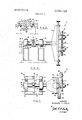
- FIG. 5 is a view in side elevation of the wire crimper of FIG. I;
- FIG. 6 is a view in rear elevation taken as indicated by the lines and arrows 6-6 which appear in FIG. 5;
- FIG. 7 is a view in top plan of the wire crimper of FIG. 1;
- FIG. 8 is a diagrammatic view in front elevation of the wire crimper with its head in vertical position with the crimping zone between wheels being on a line between the axes of the wheels and coinciding with the rotatable axis of the head member;
- FIG. 9 is a diagrammatic view in front elevation showing the wire crimper with its head rotated counterclockwise with the crimping zone being located above the rotatable axis of the head member;
- FIG. 10 is a diagrammatic view in front elevation with the head of the wire crimper being rotated clockwise and the crimping zone being located below the rotatable axis of the head member;
- FIG. 11 is a diagrammatic view of the wire crimper showing its head rotated counterclockwise;
- FIG. 12 is a partial view on an enlarged scale of the crimped wire obtained from the wire crimper of FIG. 11;
- FIG. 13 is a diagrammatic view of the wire crimper with its head rotated clockwise.
- FIG. 14 is a partial view on an enlarged scale of the crimped wire obtained from the wire crimper of FIG. 13.
- Crimper 11 for taking a curled uncrimped wire 13 from coil 15 and crimping it to obtain a straight crimped wire 17.
- Crimper 11 comprises a head member 19, a pair of crimping wheels 21, 23, means including bearing housings 25, 27 for mounting crimping wheels 21, 23 on head member 19 so that they are freewheeling and partly mesh in a mesh zone 29, and means or mechanism 31 for pulling the wire fromcoil 15 through mesh or crimping zone 29 between crimping wheels 21 and 23 in order to crimp the wire.
- Pulling mechanism 31 may be a-pair of power-driven wheels 32 having a resilient facing 34 of polyurethane. The resilient facings 34 of wheels 32 frictionally engage the sides of the crimped wire 17 since wheels 32 are in engagement.
- a lead-in guide 36 is mounted at the entrance to the bite of crimping wheels 21, 23 on level with crimping zone 29 to guide the wire 13 from the coil 15 to the crimping zone so that the wire 13 enters crimping zone 29 on a line which is tangential to crimping wheels 21, 23.
- Lead-in guide 36 includes three pairs of rollers having grooves in their circumference to pass the wire. The grooves of the middle rollers are narrower than the grooves of the pair of rollers nearest the coil 15, and the grooves of the pair of rollers nearest the crimping wheels 21, 23 are narrower than the grooves of the pair of middle rollers so that the roller grooves exert more control over the wire as it approaches the crimping zone 29.
- Head member 19 is mounted on a shaft 33 which forms the axis of the head member, and crimping wheels 21, 23 are provided with shafts 35, 37, respectively.
- Mesh zone 19 is on a line 39 between the axes 35, 37 of the wheels 21, 23 and is also on the rotatable axis 33 of the head member 19.
- Head member shaft 33 is rotatably supported in blocks 40 and is locked against rotation by a lock mechanism 41 adapted to lock the shaft 33 and head member 19 in any desired angular position.
- lock mechanism 41 When it is desired to change the angular position of the head member 19, lock mechanism 41 is released, shaft 33 is rotated to the proper setting, and mechanism 41 is relocked.
- An indicator 43 may be formed at the end of shaft 33 to show degrees of angle in cooperation with a pointer 44.
- Bearing housings 25 and 27 have an opening with roller bearings therein that rotatably support shafts 35 and 37 of the crimping wheels.
- bearing housings 25 and 27 have a slot 45 formed therein that receives a stud 47 extending outwardly from head member 19.
- the side edges of bearing housings 25 and 27 ride in parallel facing grooves 49 formed in head member 19, and a clamping nut 51 is screwed onto threaded stud 47 and is tightened to clamp the bearing housing inproper position.
- lnwardly facing grooves 49 serve to keep movement of the housing, when clamping nut 51 is untightened, along the line 39 between the axes of the crimping wheels.
- the wire is pulled by mechanism 31 from coil and through mesh zone 29 between crimping wheels 21 and 23 to obtain the crimped wire 17.
- Resilient facings 34 of the wheels 32 frictionally grasp the sides of the wire and pull the wire 17 directly from coil 15 to the crimping wheels 21, 23 without passing through any prestraightening means.
- the wire may be straightened by offsetting the head member 19 a sufficient number of degrees to curl the wire in the opposite direction and thereby obtain a straight crimped wire.
- Wire crimper 11 is a significant improvement over conventional wire crimping machines utilizing power-driven crimping wheels, and is much more economical than the proposed fully automatic crimper with electrical controls.
- Head member 19 is centrally cantilevered and balanced about its shaft 33. If desired, mechanism 41 may be unlocked so that head member 19 is free to swing or rotate to assume a position perpendicular to the force imposed by the wire as it passes between the crimping wheels 21, 23.
- Dial indicators 53, 55 are mounted on spring-loader plungers attached to head member 19 and serve to measure the position of the crimping wheels 21 and 23 relative to each other and in respect to the axis 33 of head member 19. Crimp depth is preset as follows: The wheels 21, 23 are adjusted to contact the wire between two opposing teeth, and dial indicators 53 and 55 are set to zero. Then, to obtain a 50 percent crimp depth from a .080 inch diameter wire, each wheel is intermeshed by .020 inch by moving bearing housings 25, 27 toward each other by .010 inch as indicated by dials 53,55.
- pitch distance 57 is pitch distance 57 and the other is span lengths 59 and 61. It is important to develop a constant pitch distance 57 along the length of wire 17, and it is also desirable to maintain span 59 equal to span 61 so that an extended section of crimped wire 17 progressively, and repetitively, corresponds to the pitch of an interlocking spiral wire of the conveyor belt.
- the crimped wire 17 forms the cross rods of the belt.
- One of the advantages of the invention is its ability to accept a bent or curled length of wire 13, curled because of its set in coil 15, and cause it to become straight while crimping it. This occurs when mesh zone 29 coincides with the axis 33 of head member 19, and this condition is shown diagrammatically in H0. 8.
- crimping zone 29 does not intersect axis 33 but instead is above it, and shaft 33 is unlocked, pulling the wire through the crimping wheels 21, 23 tilts head member 19 counterclockwise as shown in FIG. 9 and causes crimped wire 17a to curl upwardly.
- crimped wire 17 is straight and has a balanced crimp, provided the notch is deep enough to overcome the natural set of wire 13 imparted by coil 15.
- a .080 diameter wire was run through crimping zone 29 of wire crimper 11 with the depth of crimp set at 1 times the wire diameter, .080 inch, with the crimping zone 29 positioned so as to coincide with head member axis 33, and a crimped straight wire 17 was obtained.
- the crimped wire produced was not straight but instead retained partial coil curvature.
- the crimped wire produced was straight with the crimp depth being one-half times wire diameter, .040 inch.
- the ofi'setting of the head member 19 had overcome the coil curvature.
- the front span was not the same length as the rear span but this was not objectionable.
- FIG. 13 a clockwise offset of head member 19, with crimping zone 29 coinciding with shaft 33, produces a downward bend and a crimp as shown in FIG. 14 having a front span 67 which is shorter than rear span 69.
- locking mechanism 41 includes a clamping bar 71 which rides on shaft 33 and may be clamped onto the shaft 33 to stop any shaft rotation by bolts 73 extending from the ends of bar 71 to clamping plates 75.
- Bolts 77 attach plates 75 to a base member 79 and the plates are supported by springs 81.
- a wire crimper for crimping uncrimped wire from a coil to obtain a straight crimped wire comprising a head member, a pair of crimping wheels mounted in a plane, means for mounting the wheels on the head memberso that the crimping wheels are freewheeling and partly mesh in a mesh zone, means for pulling the wire from the coil through the mesh zone between the wheels in order to crimp the wire, and means for rotatably mounting said head member in a plane parallel to the plane of the crimping wheels and about a head member axis which is perpendicular to the plane of the crimping wheels.
- each crimping wheel is provided with a shaft
- said mounting means comprises a pair of bearing housings that rotatably support the shafts of the crimping wheels.
- the wire crimper of claim 1 including means for adjusting the angular position of the head member in a plane parallel to the plane of the crimping wheels.
- the wire crimper of claim 1 including means for adjusting the distance between wheels.
- each crimping wheel is provided with a shaft
- said mounting means comprises a pair of bearing housings having openings with bearings therein that rotatably support the shafts of the crimping wheels
- said adjusting means includes a slot formed in the bearing housing
- a stud extending from the head member into said slot, and means for clamping the housing to the stud at various positions along the slot.
- a wire crimper for crimping uncrimped wire from a coil to obtain a straight crimped Wire comprising a head mf member, a pair of crimping wheels mounted in a plane, means for mounting the crimping wheels on the head member so that the crimping wheels are freewheeling and partly mesh in a mesh zone, and means for pulling the wire from the coil through the mesh zone between the wheels in order to crimp the wire, said head member in a plane parallel to the plane of the crimping wheels and about a head member axis which is perpendicular to the plane of the crimping wheels being on a line between the axes of the wheels and also on the rotatable axis of the head member, means for adjusting the distance between crimping wheels, each crimping wheel being provided with a shaft, said mounting means including a pair of bearing housings having openings with bearings therein that rotatably support the shafts of the crimping wheels, said means for adjusting the
Abstract
A wire crimper for crimping uncrimped wire from a coil to obtain a straight crimped wire to be used in fabricating conveyor belts, comprising a head member, a pair of crimping wheels mounted on the head member in such a fashion that the crimping wheels are freewheeling and partly mesh in a mesh zone, said head member being rotatable about its axis, the mesh zone between the crimping wheels being on a line between the axes of the wheels and also on the rotatable axis of the head member, and mechanism for pulling the wire from the coil through the mesh zone between the wheels in order to crimp the wire.
Description
United States Patent I 873,200 12/1907 Alley lnventor Richard H. Field Broolnall, Pa. Appl. No. 768,715 Filed Oct. 18, 1968 Patented Feb. 23, 1971 Assignee Manganese Steel Forge Company Philadelphia, Pa.
WIRE CRIMPER 10 Claims, 14 Drawing Figs.
US. Cl 140/ 105, 72/196 Int. Cl.. B211 1/04 Field of Search 140/71,
References Cited UNITED STATES PATENTS 3,476,157 11/1969 DeWulf Primary Examiner-Lowell A. Larson Attorney-John F. A. Earley ABSTRACT: A wire crimper for crimping uncrimped wire from a coil to obtain a straight crimped wire to be used in fabricating conveyor belts, comprising a head member, a pair of crimping wheels mounted on the head member in such a fashion that the crimping wheels are freewheeling and partly mesh in a mesh zone, said head member being rotatable about its axis, the mesh zone between the crimping wheels being on a line between the axes of the wheels and also on the rotatable axis of the head member, and mechanism for pulling the wire from the coil through the mesh zone between the wheels in order to crimp the wire.
PATENTEU FEB23 I971 SHEET 1 BF 3 B V m FIG. 2.
/I Jed. 42%; ATTORNEY D I- mm NF WH D n A H m 3 R m G F G F. T (9 5 5 PATENTED 5523 I9?! sum 2 or 3 5 5 paw n w 9 5 4 B 2 EH- J1 7 o T 4 @f n 1 ll I 3 5 7 n 3 I. 1 Q. 6;;9 O F ii: 9 3 ,7 7 7 .l .7 4 7 ATTORNEY FIG. 7.
PATENTED F-EB23 I97! SHEET 3 OF 3 FIG. a.
' INVENTOR. RICHARD H. FIELD ATTORNEY WIRE CRIMPER BACKGROUND OF THE INVENTION This invention relates to the crimping of wire, and more particularly concerns the crimping of wires which are to be fabricated into conveyor belts.
In the crimping of wire for making conveyor belts, it is important that the wires be uniform and regular in order that the wire conveyor belts may be assembled easily and operate satisfactorily. In conventional wire crimping machines, crimping wheels are provided which are power-driven. The wire is fed to the power-driven crimping wheels from a coil, and the wire must undergo a prestraightening operation between the coil and the crimper so as to lose the curl which was imparted to it while wound in the coil. The straightened wire is then forced into a symmetrical pattern, generally sinusoidal in shape, by passing the wire through the pair of driven, gearshaped crimping wheels. The desired crimp-to-crimp spacing and the depth of the crimp are obtained by selecting crimping wheels of proper tooth pitch, and by setting the proper amount of mesh between the two gears. However, because of backlash in the machine gear train that drives the wheels, erraticpulling torque, and other problems, the symmetry of the crimp is distorted and the crimp imparted to the wire is erratically irregular, and this causes problems in fabricating the crimped wires into a conveyor belt.
To overcome the problems which produce irregularlycrimped wires in crimping machines having power-driven crimping wheels, it has been proposed to build a new crimping machine having a closely coupled servosystem'to maintain opposed tooth to tooth position and the required distributed torque necessary to produce an acceptable regular crimp. However, the required servo control system would be so complex and expensive that this proposal was dropped.
SUMMARY OF THE INVENTION Accordingly, it is an object of this invention to provide a wire crimper which produces an acceptable regular crimped wire suitable for fabrication into a conveyor belt, and does so without the complexity and expanse of the an electrical control system and without a prestraightener. This object is accomplished by providing a wire crimper having a pair of crimping wheels that are entirely freewheeling. The uncrimped wire is pulled through freewheeling crimping wheels mounted on a head member that is rotatable about its axis,
and the mesh zone between the wheels is on a line between the axes of the wheels. and also on the rotatable axis of the head member. The resulting crimped wire is straight, having lost the curl of the coil, and is symmetrical.
BRIEF DESCRIPTION OF THE DRAWINGS Other objects and advantages of the invention, including its simplicity and economy, will further become apparent hereinafter and in the drawings, in which:
FIG. 1 is a view in front elevation of a wire crimper constructed in accordance with this invention;
FIG. 2 is a view in section taken as indicated by the lines and arrows 2-2 which appear in FIG. 1;
FIG. 3 is an overall view, partly diagrammatic, of the wire crimping apparatus including the coil, the lead-in guide, the wire crimper, and the wire pulling mechanism;
FIG. 4 is an enlarged partial view of the crimped wire produced by the wire crimper;
FIG. 5 is a view in side elevation of the wire crimper of FIG. I;
FIG. 6 is a view in rear elevation taken as indicated by the lines and arrows 6-6 which appear in FIG. 5;
FIG. 7 is a view in top plan of the wire crimper of FIG. 1;
FIG. 8 is a diagrammatic view in front elevation of the wire crimper with its head in vertical position with the crimping zone between wheels being on a line between the axes of the wheels and coinciding with the rotatable axis of the head member;
FIG. 9 is a diagrammatic view in front elevation showing the wire crimper with its head rotated counterclockwise with the crimping zone being located above the rotatable axis of the head member;
FIG. 10 is a diagrammatic view in front elevation with the head of the wire crimper being rotated clockwise and the crimping zone being located below the rotatable axis of the head member;
FIG. 11 is a diagrammatic view of the wire crimper showing its head rotated counterclockwise;
FIG. 12 is a partial view on an enlarged scale of the crimped wire obtained from the wire crimper of FIG. 11;
FIG. 13 is a diagrammatic view of the wire crimper with its head rotated clockwise; and
FIG. 14 is a partial view on an enlarged scale of the crimped wire obtained from the wire crimper of FIG. 13.
DESCRIPTION OF PREFERRED EMBODIMENT Although specific terms are used in the following description for clarity, these terms are intended to'refer only to the structure shown in the drawings and are not intended to define or limit the scope of the invention.
Turning now to the specific embodiment of the invention selected for illustration on the drawings, there is shown a wire crimper 1 I for taking a curled uncrimped wire 13 from coil 15 and crimping it to obtain a straight crimped wire 17. Crimper 11 comprises a head member 19, a pair of crimping wheels 21, 23, means including bearing housings 25, 27 for mounting crimping wheels 21, 23 on head member 19 so that they are freewheeling and partly mesh in a mesh zone 29, and means or mechanism 31 for pulling the wire fromcoil 15 through mesh or crimping zone 29 between crimping wheels 21 and 23 in order to crimp the wire. Pulling mechanism 31 may be a-pair of power-driven wheels 32 having a resilient facing 34 of polyurethane. The resilient facings 34 of wheels 32 frictionally engage the sides of the crimped wire 17 since wheels 32 are in engagement.
A lead-in guide 36 is mounted at the entrance to the bite of crimping wheels 21, 23 on level with crimping zone 29 to guide the wire 13 from the coil 15 to the crimping zone so that the wire 13 enters crimping zone 29 on a line which is tangential to crimping wheels 21, 23. Lead-in guide 36 includes three pairs of rollers having grooves in their circumference to pass the wire. The grooves of the middle rollers are narrower than the grooves of the pair of rollers nearest the coil 15, and the grooves of the pair of rollers nearest the crimping wheels 21, 23 are narrower than the grooves of the pair of middle rollers so that the roller grooves exert more control over the wire as it approaches the crimping zone 29.
Bearing housings 25 and 27 have an opening with roller bearings therein that rotatably support shafts 35 and 37 of the crimping wheels.
To adjust the distance between crimping wheels, bearing housings 25 and 27 have a slot 45 formed therein that receives a stud 47 extending outwardly from head member 19. The side edges of bearing housings 25 and 27 ride in parallel facing grooves 49 formed in head member 19, and a clamping nut 51 is screwed onto threaded stud 47 and is tightened to clamp the bearing housing inproper position. lnwardly facing grooves 49 serve to keep movement of the housing, when clamping nut 51 is untightened, along the line 39 between the axes of the crimping wheels.
In operation, the wire is pulled by mechanism 31 from coil and through mesh zone 29 between crimping wheels 21 and 23 to obtain the crimped wire 17. Resilient facings 34 of the wheels 32 frictionally grasp the sides of the wire and pull the wire 17 directly from coil 15 to the crimping wheels 21, 23 without passing through any prestraightening means.
If the desired crimped depth is deep enough, the curl of the wire from the coil is overcome, and crimped wire 17 is straight. However, if the desired crimp is a light crimp that does not straighten the wire, the wire may be straightened by offsetting the head member 19 a sufficient number of degrees to curl the wire in the opposite direction and thereby obtain a straight crimped wire.
It is to be noted that the pull on the wire need not be in a horizontal direction just so long as the axis 33 of the head member 19 is midway between the crimping wheels so as tocoincide with crimping or mesh zone 29. Wire crimper 11 is a significant improvement over conventional wire crimping machines utilizing power-driven crimping wheels, and is much more economical than the proposed fully automatic crimper with electrical controls.
There are two factors that define the symmetry of a single crimped element as shown in FIG. 4. One is pitch distance 57 and the other is span lengths 59 and 61. It is important to develop a constant pitch distance 57 along the length of wire 17, and it is also desirable to maintain span 59 equal to span 61 so that an extended section of crimped wire 17 progressively, and repetitively, corresponds to the pitch of an interlocking spiral wire of the conveyor belt. The crimped wire 17 forms the cross rods of the belt.
One of the advantages of the invention is its ability to accept a bent or curled length of wire 13, curled because of its set in coil 15, and cause it to become straight while crimping it. This occurs when mesh zone 29 coincides with the axis 33 of head member 19, and this condition is shown diagrammatically in H0. 8.
However, if crimping zone 29 does not intersect axis 33 but instead is above it, and shaft 33 is unlocked, pulling the wire through the crimping wheels 21, 23 tilts head member 19 counterclockwise as shown in FIG. 9 and causes crimped wire 17a to curl upwardly.
If mesh or crimping zone 29 is located below axis 33 and shaft 33 is unlocked, pulling the wire through crimping wheels 21, 23 tilts head member 19 clockwise to the position shown in FIG. 10 and crimped wire 17b assumes a curl downwardly.
Accordingly, if crimping zone 29 coincides with axis 33, crimped wire 17 is straight and has a balanced crimp, provided the notch is deep enough to overcome the natural set of wire 13 imparted by coil 15.
For example, a .080 diameter wire was run through crimping zone 29 of wire crimper 11 with the depth of crimp set at 1 times the wire diameter, .080 inch, with the crimping zone 29 positioned so as to coincide with head member axis 33, and a crimped straight wire 17 was obtained.
When the crimped depth was reduced to one-half times wire diameter, .040 inch, the crimped wire produced was not straight but instead retained partial coil curvature. However, when the head member 19 was rotated clockwise, the opposite direction to the coil curvature, the crimped wire produced was straight with the crimp depth being one-half times wire diameter, .040 inch. The ofi'setting of the head member 19 had overcome the coil curvature. The front span was not the same length as the rear span but this was not objectionable.
Referring to FIG. 11, a counterclockwise offset of head member 19, with crimping zone 29 coinciding with shaft 33, produces an upward bend and a crimp as shown in FIG. 12 with front span 63 being longer than rear span 65.
Referring to FIG. 13, a clockwise offset of head member 19, with crimping zone 29 coinciding with shaft 33, produces a downward bend and a crimp as shown in FIG. 14 having a front span 67 which is shorter than rear span 69.
Referring more particularly to FIG. 57 locking mechanism 41 includes a clamping bar 71 which rides on shaft 33 and may be clamped onto the shaft 33 to stop any shaft rotation by bolts 73 extending from the ends of bar 71 to clamping plates 75. Bolts 77 attach plates 75 to a base member 79 and the plates are supported by springs 81.
To check the accumulated a error along a given length of crimped wire, two sections were cut from selected runs and mounted on a strip of plywood, one on top of the other. Nails were placed at random crimp notches approximately 12 to 15 inches apart to secure the and align the samples. Visual inspection detected no relative error or out-of-phase progression. Then the top length was removed and turned end-for-end and replaced as before. The crimps again matched quite perfectly indicating a well-formed symmetrical shape.
It is to be understood that the form of the invention herewith shown and described is to be taken as a presently preferred embodiment. Various changes may be made in the shape, size and arrangement of parts. For example, equivalent elements may be substituted for those illustrated and described herein, parts may be reversed, and certain features of the invention may be utilized independently of the use of other features, all without departing from the spirit or scope of the invention as defined in the subjoined claims.
I claim:
l. A wire crimper for crimping uncrimped wire from a coil to obtain a straight crimped wire, comprising a head member, a pair of crimping wheels mounted in a plane, means for mounting the wheels on the head memberso that the crimping wheels are freewheeling and partly mesh in a mesh zone, means for pulling the wire from the coil through the mesh zone between the wheels in order to crimp the wire, and means for rotatably mounting said head member in a plane parallel to the plane of the crimping wheels and about a head member axis which is perpendicular to the plane of the crimping wheels.
2. The wire crimper of claim 1 wherein the mesh zone between said wheels is on a line between the axes of the wheels.
3. The wire crimper of claim 1 wherein the mesh zone between said wheels is. on the rotatable axis of said head member.
4. The wire crimper of claim 1 wherein the mesh zone between said wheels is on a line between the axes of the wheels and also on the rotatable axis of the head member.
5. The wire crimper of claim 1 wherein each crimping wheel is provided with a shaft, and said mounting means comprises a pair of bearing housings that rotatably support the shafts of the crimping wheels.
6. The wire crimper of claim 1, including means for adjusting the angular position of the head member in a plane parallel to the plane of the crimping wheels.
7. The wire crimper of claim 1 including means for adjusting the distance between wheels.
8. The wire crimper of claim 7 wherein each crimping wheel is provided with a shaft, said mounting means comprises a pair of bearing housings having openings with bearings therein that rotatably support the shafts of the crimping wheels, and said adjusting means includes a slot formed in the bearing housing,
a stud extending from the head member into said slot, and means for clamping the housing to the stud at various positions along the slot.
9 The wire crimper of claim 1, wherein the pulling means is a pair of power-driven wheels which have resilient facings that frictionally grasp the sides of the crimped wire and pull the uncrimped wire directly from the 'coil to the crimping wheels without passing through any prestraightening means.
10. A wire crimper for crimping uncrimped wire from a coil to obtain a straight crimped Wire, comprising a head mf member, a pair of crimping wheels mounted in a plane, means for mounting the crimping wheels on the head member so that the crimping wheels are freewheeling and partly mesh in a mesh zone, and means for pulling the wire from the coil through the mesh zone between the wheels in order to crimp the wire, said head member in a plane parallel to the plane of the crimping wheels and about a head member axis which is perpendicular to the plane of the crimping wheels being on a line between the axes of the wheels and also on the rotatable axis of the head member, means for adjusting the distance between crimping wheels, each crimping wheel being provided with a shaft, said mounting means including a pair of bearing housings having openings with bearings therein that rotatably support the shafts of the crimping wheels, said means for adjusting the distance between crimping wheels including a slot formed in each bearing housing, a stud extending from the head member into, each slot, and means for clamping each housing to its stud at various positions along the slot, said pulling means including a pair of power-driven wheels which have resilient facings that frictionally grasp the sides of the crimped wire and pull the uncrimped wire directly from the coil to the crimping wheels without passing through any prestraightening means.
Claims (9)
1. A wire crimper for crimping uncrimped wire from a coil to obtain a straight crimped wire, comprising a head member, a pair of crimping wheels mounted in a plane, means for mounting the wheels on the head member so that the crimping wheels are freewheeling and partly mesh in a mesh zone, means for pulling the wire from the coil through the mesh zone between the wheels in order to crimp the wire, and means for rotatably mounting said head member in a plane parallel to the plane of the crimping wheels and about a head member axis which is perpendicular to the plane of the crimping wheels. 2. The wire crimper of claim 1 wherein the mesh zone between said wheels is on a line between the axes of the wheels.
3. The wire crimper of claim 1 wherein the mesh zone between said wheels is on the rotatable axis of said head member.
4. The wire crimper of claim 1 wherein the mesh zone between said wheels is on a line between the axes of the wheels and also on the rotatable axis of the head member.
5. The wire crimper of claim 1 wherein each crimping wheel is provided with a shaft, and said mounting means comprises a pair of bearing housings that rotatably support the shafts of the crimping wheels.
6. The wire crimper of claim 1, including means for adjusting the angular position of the head member in a plane parallel to the plane of the crimping wheels.
7. The wire crimper of claim 1 including means for adjusting the distance between wheels.
8. The wire crimper of claim 7 wherein each crimping wheel is provided with a shaft, said mounting means comprises a pair of bearing housings having openings with bearings therein that rotatably support the shafts of the crimping wheels, and said adjusting means includes a slot formed in the bearing housing, a stud extending from the head member into said slot, and means for clamping the housing to the stud at various positions along the slot.
9. The wire crimper of claim 1, wherein the pulling means is a pair of power-driven wheels which have resilient facings that frictionally grasp the sides of the crimped wire and pull the uncrimped wire directly from the coil to the crimping wheels without passing through any prestraightening means.
10. A wire crimper for crimping uncrimped wire from a coil to obtain a straight crimped wire, comprising a head mf member, a pair of crimping wheels mounted in a plane, means for mounting the crimping wheels on the head member so that the crimping wheels are freewheeling and partly mesh in a mesh zone, and means for pulling the wire from the coil through the mesh zone between the wheels in order to crimp the wire, said head member in a plane parallel to the plane of the crimping wheels and about a head member axis which is perpendicular to the plane of the crimping wheels being on a line between the axes of the wheels and also on the rotatable axis of the head member, means for adjusting the distance between crimping wheels, each crimping wheel being provided with a shaft, said mounting means including a pair of bearing housings having openings with bearings therein that rotatably support the shafts of the crimping wheels, said means for adjusting the distance between crimping wheels including a slot formed in each bearing housing, a stud extending from the head member into each slot, and means for clamping each housing to its stud at various positions along the slot, said pulling means including a pair of power-driven wheels which have resilient facings that frictionally grasp the sides of the crimped wire and pull the uncrimped wire directly from the coil to the crimping wheels without passing through any prestraightening means.
Applications Claiming Priority (1)
| Application Number | Priority Date | Filing Date | Title |
|---|---|---|---|
| US76871568A | 1968-10-18 | 1968-10-18 |
Publications (1)
| Publication Number | Publication Date |
|---|---|
| US3565129A true US3565129A (en) | 1971-02-23 |
Family
ID=25083297
Family Applications (1)
| Application Number | Title | Priority Date | Filing Date |
|---|---|---|---|
| US768715A Expired - Lifetime US3565129A (en) | 1968-10-18 | 1968-10-18 | Wire crimper |
Country Status (1)
| Country | Link |
|---|---|
| US (1) | US3565129A (en) |
Cited By (26)
| Publication number | Priority date | Publication date | Assignee | Title |
|---|---|---|---|---|
| US3805853A (en) * | 1973-01-02 | 1974-04-23 | Us Navy | Apparatus for making transducer scroll spacers |
| FR2464763A1 (en) * | 1979-09-12 | 1981-03-20 | Marlin Aime | Wire forming machine with meshing gears - has wire passing through space between frusto=conical gears with spindles geared to separate intermeshing train |
| EP1266717A1 (en) * | 2001-06-15 | 2002-12-18 | Lincoln Global, Inc. | "S" shaped cast in weld wire |
| EP1726375A1 (en) | 2005-05-25 | 2006-11-29 | Lincoln Global, Inc. | Method for forming a large diameter weld wire by imparting a desired shape memory on said wire; A packaged supply of wire and a weld wire with such imparted shape memory form |
| US20070295853A1 (en) * | 1996-07-24 | 2007-12-27 | Giancarlo Cipriani | Mechanism for braking the unwinding of a bundle of metallic wire housed in a drum |
| US20080289389A1 (en) * | 2007-05-25 | 2008-11-27 | Fitch Bradley A | Wire-forming apparatus |
| US20090090344A1 (en) * | 2004-12-23 | 2009-04-09 | Trefilarbed Bettembourg S.A. | Monofilament metal saw wire |
| US20100084296A1 (en) * | 2008-10-07 | 2010-04-08 | Carlo Gelmetti | Cover for welding wire container |
| US20100230525A1 (en) * | 2009-03-10 | 2010-09-16 | Lincoln Global, Inc. | Wire dispensing apparatus for packaged wire |
| US20110042254A1 (en) * | 2009-08-21 | 2011-02-24 | Carlo Gelmetti | Retainer for welding wire container, having fingers and half-moon shaped holding tabs |
| US20110094911A1 (en) * | 2009-08-21 | 2011-04-28 | Carlo Gelmetti | Retainer for welding wire container, having fingers and half-moon shaped holding tabs |
| US8389901B1 (en) | 2010-05-27 | 2013-03-05 | Awds Technologies Srl | Welding wire guiding liner |
| US8453960B2 (en) | 2008-05-27 | 2013-06-04 | Awds Technologies Srl | Wire guiding system |
| US8674263B2 (en) | 2009-07-20 | 2014-03-18 | Awds Technologies Srl | Wire guiding liner, in particular a welding wire liner, with biasing means between articulated guiding bodies |
| US8882018B2 (en) | 2011-12-19 | 2014-11-11 | Sidergas Spa | Retainer for welding wire container and welding wire container with retainer |
| US9296034B2 (en) | 2011-07-26 | 2016-03-29 | Medtronic Vascular, Inc. | Apparatus and method for forming a wave form for a stent from a wire |
| US20160096218A1 (en) * | 2012-04-18 | 2016-04-07 | Medtronic Vascular, Inc. | Method and Apparatus for Creating Formed Elements Used to Make Wound Stents |
| US20160114376A1 (en) * | 2012-04-03 | 2016-04-28 | Medtronic Vascular, Inc. | Method and Apparatus for Creating Formed Elements Used to Make Wound Stents |
| US9950857B1 (en) | 2016-10-17 | 2018-04-24 | Sidergas Spa | Welding wire container |
| US9975728B2 (en) | 2015-09-10 | 2018-05-22 | Sidergas Spa | Wire container lid, wire container and wire feeding system |
| US10010962B1 (en) | 2014-09-09 | 2018-07-03 | Awds Technologies Srl | Module and system for controlling and recording welding data, and welding wire feeder |
| US10294065B2 (en) | 2013-06-06 | 2019-05-21 | Sidergas Spa | Retainer for a welding wire container and welding wire container |
| US10343231B2 (en) | 2014-05-28 | 2019-07-09 | Awds Technologies Srl | Wire feeding system |
| US10350696B2 (en) | 2015-04-06 | 2019-07-16 | Awds Technologies Srl | Wire feed system and method of controlling feed of welding wire |
| US11174121B2 (en) | 2020-01-20 | 2021-11-16 | Awds Technologies Srl | Device for imparting a torsional force onto a wire |
| US11278981B2 (en) | 2020-01-20 | 2022-03-22 | Awds Technologies Srl | Device for imparting a torsional force onto a wire |
Citations (2)
| Publication number | Priority date | Publication date | Assignee | Title |
|---|---|---|---|---|
| US873200A (en) * | 1906-12-26 | 1907-12-10 | Jesse L Alley | Wire-crimping machine. |
| US3476157A (en) * | 1967-09-18 | 1969-11-04 | United States Steel Corp | Variable-pitch wire crimping means |
-
1968
- 1968-10-18 US US768715A patent/US3565129A/en not_active Expired - Lifetime
Patent Citations (2)
| Publication number | Priority date | Publication date | Assignee | Title |
|---|---|---|---|---|
| US873200A (en) * | 1906-12-26 | 1907-12-10 | Jesse L Alley | Wire-crimping machine. |
| US3476157A (en) * | 1967-09-18 | 1969-11-04 | United States Steel Corp | Variable-pitch wire crimping means |
Cited By (41)
| Publication number | Priority date | Publication date | Assignee | Title |
|---|---|---|---|---|
| US3805853A (en) * | 1973-01-02 | 1974-04-23 | Us Navy | Apparatus for making transducer scroll spacers |
| FR2464763A1 (en) * | 1979-09-12 | 1981-03-20 | Marlin Aime | Wire forming machine with meshing gears - has wire passing through space between frusto=conical gears with spindles geared to separate intermeshing train |
| US20070295853A1 (en) * | 1996-07-24 | 2007-12-27 | Giancarlo Cipriani | Mechanism for braking the unwinding of a bundle of metallic wire housed in a drum |
| USRE43352E1 (en) | 1996-07-24 | 2012-05-08 | Lincoln Global, Inc. | Mechanism for braking the unwinding of a bundle of metallic wire housed in a drum |
| EP1266717A1 (en) * | 2001-06-15 | 2002-12-18 | Lincoln Global, Inc. | "S" shaped cast in weld wire |
| US20040020041A1 (en) * | 2001-06-15 | 2004-02-05 | Lincoln Global, Inc., A Delaware Corporation | "S" shaped cast in wire |
| US6708864B2 (en) | 2001-06-15 | 2004-03-23 | Lincoln Global, Inc. | “S” shaped cast in wire |
| US6820454B2 (en) | 2001-06-15 | 2004-11-23 | Lincoln Global, Inc. | “S” shaped cast in wire |
| US20090090344A1 (en) * | 2004-12-23 | 2009-04-09 | Trefilarbed Bettembourg S.A. | Monofilament metal saw wire |
| US9610641B2 (en) * | 2004-12-23 | 2017-04-04 | Arcelormittal Bissen & Bettembourg | Monofilament metal saw wire |
| US20060266794A1 (en) * | 2005-05-25 | 2006-11-30 | Lincoln Global, Inc. | Method and apparatus for packaging wire in a wire container |
| EP1726375A1 (en) | 2005-05-25 | 2006-11-29 | Lincoln Global, Inc. | Method for forming a large diameter weld wire by imparting a desired shape memory on said wire; A packaged supply of wire and a weld wire with such imparted shape memory form |
| US20080289389A1 (en) * | 2007-05-25 | 2008-11-27 | Fitch Bradley A | Wire-forming apparatus |
| US8453960B2 (en) | 2008-05-27 | 2013-06-04 | Awds Technologies Srl | Wire guiding system |
| US20100084296A1 (en) * | 2008-10-07 | 2010-04-08 | Carlo Gelmetti | Cover for welding wire container |
| US8668086B2 (en) | 2008-10-07 | 2014-03-11 | Sidergas Spa | Cover for welding wire container |
| US20100230525A1 (en) * | 2009-03-10 | 2010-09-16 | Lincoln Global, Inc. | Wire dispensing apparatus for packaged wire |
| US20110000998A1 (en) * | 2009-03-10 | 2011-01-06 | Lincoln Global, Inc. | Wire dispensing apparatus for packaged wire |
| US8794561B2 (en) | 2009-03-10 | 2014-08-05 | Lincoln Global, Inc. | Wire dispensing apparatus for packaged wire |
| US7938352B2 (en) | 2009-03-10 | 2011-05-10 | Lincoln Global, Inc. | Wire dispensing apparatus for packaged wire |
| US8674263B2 (en) | 2009-07-20 | 2014-03-18 | Awds Technologies Srl | Wire guiding liner, in particular a welding wire liner, with biasing means between articulated guiding bodies |
| US8393467B2 (en) | 2009-08-21 | 2013-03-12 | Sidergas Spa | Retainer for welding wire container, having fingers and half-moon shaped holding tabs |
| US20110042254A1 (en) * | 2009-08-21 | 2011-02-24 | Carlo Gelmetti | Retainer for welding wire container, having fingers and half-moon shaped holding tabs |
| US8235211B2 (en) | 2009-08-21 | 2012-08-07 | Sidergas Spa | Retainer for welding wire container, having fingers and half-moon shaped holding tabs |
| US20110094911A1 (en) * | 2009-08-21 | 2011-04-28 | Carlo Gelmetti | Retainer for welding wire container, having fingers and half-moon shaped holding tabs |
| US8389901B1 (en) | 2010-05-27 | 2013-03-05 | Awds Technologies Srl | Welding wire guiding liner |
| US9296034B2 (en) | 2011-07-26 | 2016-03-29 | Medtronic Vascular, Inc. | Apparatus and method for forming a wave form for a stent from a wire |
| US10518315B2 (en) | 2011-07-26 | 2019-12-31 | Medtronic Vascular, Inc. | Apparatus and method for forming a wave form for a stent from a wire |
| US8882018B2 (en) | 2011-12-19 | 2014-11-11 | Sidergas Spa | Retainer for welding wire container and welding wire container with retainer |
| US9676022B2 (en) * | 2012-04-03 | 2017-06-13 | Medtronic Vascular, Inc. | Apparatus for creating formed elements used to make wound stents |
| US20160114376A1 (en) * | 2012-04-03 | 2016-04-28 | Medtronic Vascular, Inc. | Method and Apparatus for Creating Formed Elements Used to Make Wound Stents |
| US9901973B2 (en) * | 2012-04-18 | 2018-02-27 | Medtronic Vascular, Inc. | Method and apparatus for creating formed elements used to make wound stents |
| US20160096218A1 (en) * | 2012-04-18 | 2016-04-07 | Medtronic Vascular, Inc. | Method and Apparatus for Creating Formed Elements Used to Make Wound Stents |
| US10294065B2 (en) | 2013-06-06 | 2019-05-21 | Sidergas Spa | Retainer for a welding wire container and welding wire container |
| US10343231B2 (en) | 2014-05-28 | 2019-07-09 | Awds Technologies Srl | Wire feeding system |
| US10010962B1 (en) | 2014-09-09 | 2018-07-03 | Awds Technologies Srl | Module and system for controlling and recording welding data, and welding wire feeder |
| US10350696B2 (en) | 2015-04-06 | 2019-07-16 | Awds Technologies Srl | Wire feed system and method of controlling feed of welding wire |
| US9975728B2 (en) | 2015-09-10 | 2018-05-22 | Sidergas Spa | Wire container lid, wire container and wire feeding system |
| US9950857B1 (en) | 2016-10-17 | 2018-04-24 | Sidergas Spa | Welding wire container |
| US11174121B2 (en) | 2020-01-20 | 2021-11-16 | Awds Technologies Srl | Device for imparting a torsional force onto a wire |
| US11278981B2 (en) | 2020-01-20 | 2022-03-22 | Awds Technologies Srl | Device for imparting a torsional force onto a wire |
Similar Documents
| Publication | Publication Date | Title |
|---|---|---|
| US3565129A (en) | Wire crimper | |
| US4546631A (en) | Roller mechanism for forming helical shapes | |
| EP3579991B1 (en) | Machine and method for manufacturing a reinforced net and reinforced net | |
| US3724249A (en) | Method of and device for the coiling of metal tape or strip | |
| US3606783A (en) | Segmented roll for forming helically corrugated pipe | |
| US2778385A (en) | Apparatus and method for forming sinuous wire structural and heat exchange elements | |
| US4179912A (en) | Apparatus and methods for forming panels having scalloped cross-sections | |
| US2317530A (en) | Helix former | |
| US3476157A (en) | Variable-pitch wire crimping means | |
| US2148357A (en) | Wire straightening apparatus | |
| US3742747A (en) | Method for shaping indented steel wire and apparatus therefor | |
| US1862345A (en) | Apparatus for manufacturing wire ropes and the like | |
| US4884425A (en) | Roll forming apparatus for forming barbed tape into a coded configuration | |
| US4036045A (en) | Calibrated adjustable roll straightener for wire | |
| GB1471812A (en) | Method of rolling metal blanks | |
| US2591943A (en) | Helix former | |
| US3044501A (en) | Wire crimping apparatus | |
| EP0127224A1 (en) | Device for measuring the single flank error of a pair of intermeshing toothed wheels | |
| US332572A (en) | Machine for reducing wire rods | |
| GB1321209A (en) | Coin stacker in automatic coin wrapping apparatus | |
| US603868A (en) | atkins | |
| US3137337A (en) | Apparatus for and methods of making a sheet metal strip structure | |
| US3238754A (en) | Method and machine for making noncumulative force springs | |
| US1987741A (en) | Wire straightener | |
| US1963661A (en) | Metal bending machine |