US2503539A - Power-operated hand tool for scraping and feathering - Google Patents
Power-operated hand tool for scraping and feathering Download PDFInfo
- Publication number
- US2503539A US2503539A US674783A US67478346A US2503539A US 2503539 A US2503539 A US 2503539A US 674783 A US674783 A US 674783A US 67478346 A US67478346 A US 67478346A US 2503539 A US2503539 A US 2503539A
- Authority
- US
- United States
- Prior art keywords
- blade
- flywheel
- crank pin
- feathering
- scraping
- Prior art date
- Legal status (The legal status is an assumption and is not a legal conclusion. Google has not performed a legal analysis and makes no representation as to the accuracy of the status listed.)
- Expired - Lifetime
Links
Images
Classifications
-
- B—PERFORMING OPERATIONS; TRANSPORTING
- B23—MACHINE TOOLS; METAL-WORKING NOT OTHERWISE PROVIDED FOR
- B23D—PLANING; SLOTTING; SHEARING; BROACHING; SAWING; FILING; SCRAPING; LIKE OPERATIONS FOR WORKING METAL BY REMOVING MATERIAL, NOT OTHERWISE PROVIDED FOR
- B23D79/00—Methods, machines, or devices not covered elsewhere, for working metal by removal of material
Definitions
- Patented Apr. 11, 1950 POWER-OPERATED HAND TOOL FOR SCRAPING AND FEATHERING Reginald James Aspeek, East Ham, England, assignor to Coborn Engineering Company Limited, Barkingside, Essex, England Application June 6, 1946, Serial No. 674,783 In Great Britain June 14, 1945 7 Claims.
- This invention relates to power-operated hand tools and particularly to a power-operated hand tool for scraping and feathering the surface of metal sheets.
- a poweroperated hand tool for scraping or feathering comprises a blade with a substantially arcuate cutting edge, means for reciprocating said blade along a line normal to the centre of said cutting edge, means for simultaneously causing said blade to rock about said line as axis, said means including a flywheel of substantial mass, a housing for said means and a power-driving connection thereto.
- a net weight of about 12 to 1'7 lbs. is generally suitable but lower net weights may be employed if the reciprocating movement is relatively short and/or the speed of the reciprocating movement is relatively high.
- a preferred method of effecting the combined reciprocating and rocking motion of the blade is to secure the blade in a holder connected to an eccentric crank pin secured to one face of the flywheel, the crank pin being set at an angle to the normal, i. e. by using a so-called wobble crank pin.
- the holder is then located in a trunnion fitted on the crank pin, the trunnion permitting the rocking motion.
- the eccentricity of the crank pin causes the reciprocating movement while the inclination of the crank pin introduces the rocking motion.
- the same system may also be set up to reverse these functions, i. e. so that the eccentricity of the crank pin introduces the rocking motion and the inclination of the crank pin causes the reciprocating movement.
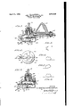
- Figure 1 is a diagrammatic cross-section through the whole tool, showing the tool blade in a rearward position.
- Figure 2 is a diagrammatic plan of part of the tool.
- FIGS 3, 4, 5 and 6 diagrammatically illustrate the movement of the cutting blade and the shape of the cut obtained.
- Fig. 7 is somewhat similar to Fig. 1 and shows the blade of the tool disposed in a forward position.
- the tool comprises a body casing I I provided with two handles I2 and I3 adapted to be grasped by the operator.
- the handle I 3v is set at right angles to the handle I2.
- a shaft I4 running in bearings I5 and I6. These bearings are separated by a sleeve I1 and the shaft I4 is connected via a connection I8 to a flexible shaft I9 which may be connected to a power supply.
- a driving member in the form of a truncated cone 20. This is intended to drive by friction and may conveniently be made of a plastic such as Bakelite
- the cone 20 engages with a iiywheel 2
- has an upwardly projecting shaft 22 which is located in a sleeve 23 to which it is locked by a bolt 24.
- the sleeve 23 is located within a second sleeve 25, rotating within it on ball races 26 and 21. This second sleeve 25 is locked to the body II by bolts 28.
- the bearings 26 and 2l are so designed that they carry the weight of the fiywheel 2l.
- the lower surface of the flywheel 2 I is provided with a slot 29 in which a slide member 30 may be adjusted by means of screws -3
- crank pin 32 may thus, by adjustment of the position of the slide member 3
- the crank pin 32 is set at a small angle to the axis of the flywheel 2
- crank pin 32 is mounted for free rotation in a bush 33 secured by trunnions 34 across the fork 35 of a blade holding member 36.
- a cutting blade 38 having an arcuate cutting edge, 39.
- the member 36 is mounted for reciprocating movement on a single ball bearing 4U mounted between a pair of V-shaped grooves 4
- Springs 43 anchored at one end to the body casing and at the other end to the blade holding member 36, hold the blade member and body casing in juxtaposition.
- the lower part 44 of the body casing is cut away to allow for movement of the member 36 and is removable to enable the interior of the tool to be assembled, adjusted or inspected.
- Figures 4, 5 and 6 of the drawings The actual movement of the cutting blade is illustrated in Figures 4, 5 and 6 of the drawings.
- Figure 4 shews the blade at the commencement of' its forward stroke
- Figure 5 shews the blade at its mid-position
- Figure 6 shews the blade at the end of its stroke.
- the blade rocks similarly on its return movement but of course does not exert any cutting action.
- the shape of the cut obtained (in the direction of the arrow) is diagrammatically indicated in Figure 3 and it is such that the depression formed by the cut grades off imperceptibly into the main surface of the metal. leaving no sharp edges.
- a general purpose tool according to this invention may conveniently be designed so that the reciprocation is of the order of 30D-500 strokes per minute, the length l of the reciprocation being from about 3/8 to 11A".
- the inclination of the crank pin may conveniently be about 2 degrees to the axis of the flywheel.
- a flywheel of substantial mass is required and the net weight of the tool may be about 15 lbs.
- the weight may be reduced, for example, to '7 to 12 lbs. and the speed of reciprocation increased to say 500 to 1500 strokes per minute and the length of the stroke reduced, say to 1A, to W8".
- the cutting blade has a vsubstantially arcuate cutting edge. This need not be an absolutely true arc but may if desired have a greater degree of curvature towards the ends of the arc than at its centre. An arc of about 4 inch radius has been found very suitable. It is not absolutely necessary for the blade to be symmetrical since, as will be apparent from Figures 4, 5 and 6 one half of the blade does not exert a cutting action. Nevertheless it is convenient to make the blade symmetrical as it may then be removed from the blade-holding member, turned over and replaced, thus bringing the other half of it into cutting operation.
- the cutting blade has a vsubstantially arcuate cutting edge. This need not be an absolutely true arc but may if desired have a greater degree of curvature towards the ends of the arc than at its centre. An arc of about 4 inch radius has been found very suitable. It is not absolutely necessary for the blade to be symmetrical since, as will be apparent from Figures 4, 5 and 6 one half of the blade does not exert a cutting action.
- cutter blade is conveniently a tungsten tipped blade.
- the flywheel may be made to rotate on a horizontal axis and may be spring-loaded to take up some of the reactionary thrust of the cutting blade.
- the bearing for the blade-holding member is a single ball, any other form of bearing which will permit the three movements of the member, i. e. reciprocating, rocking, and side-to-side, all resultant on the movement of the crank pin, may be employed.
- a suitable alternative is a tubular sleeve bearing mounted on a vertical trunnion.
- a power-operated hand tool for scraping or feathering which comprises a blade with a substantially arcuate cutting edge, a flywheel of substantial mass, an eccentrically mounted crank pin located on the face of said flywheel, a blade-holding member connecting said crank pin and said blade, whereby rotation of said fly wheel causes a reciprocating movement of said member and therefore of said blade on a line normal to the centre of its cutting edge, said crank pin being disposed at a small angle to the axis of said flywheel whereby rotation of said flywheel causes simultaneously a rocking movement of said blade about said line as axis, a housing for said flywheel, crank pin and bladeholding member and a power driving connection to said flywheel.
- a power-operated hand tool for scraping or feathering which comprises a blade with a substantially arcuate cutting edge, a flywheel of substantial mass, an eccentrically mounted crank pin located on the face of said flywheel, a blade-holding member connecting said crank pin and said blade, whereby rotation of said flywheel causes a reciprocating movement of said member and therefore of said blade on a line normal to the centre of its cutting edge, said crank-pin being disposed at a small angle to the axis of said flywheel and said blade-holding member being connected to said crank pin by a trunnion connection, whereby rotation of said flywheel causes simultaneously a rocking movement of said blade, permitted by said trunnion, about said line as axis, a housing for said flywheel, crank pin, blade-holding member and trunnion connection, and a power driving connection to said flywheel.
- a power-operated hand tool for scraping or feathering which comprises a blade with a substantially arcuate cutting edge, a flywheel of substantial mass, an eccentrically mounted crank pin located on the face of said flywheel, a bladeholding member connecting said crank pin and said blade, whereby rotation of said flywheel causes a reciprocating movement of said member and therefore of said blade on a line normal to the centre of its cutting edge, said crank pin being -disposed at a small angle to the axis of said flywheel and said blade-holding member being connected to said crank pin by a trunnion connection, whereby rotation of said flywheel causes simultaneously a rocking movementl of said blade, permitted by said trunnion, about said line as axis, said blade-holding member being mounted for movement in a bearing permitting the reciprocation, rocking and side-toside movement thereof, a housing for said flywheel, crank pin, blade-holding member and trunnion connection, and a power driving connection to said flywheel.
- a power-operated hand tool for scraping or feathering which comprises a blade with a substantially arcuate cutting edge, a flywheel of substantial mass, an eccentrically mounted crank pin located on the face of said flywheel, a bladeholding member connecting said crank pin and said blade, whereby rotation of said ywheel causes a reciprocating movement of said member and therefore of said blade on a line normal to the centre of its cutting edge, said crank pin being disposed at a small angle to the axis of said flywheel and said blade-holding member being connected to said crank pin by a trunnion connection, whereby rotation of said flywheel causes simultaneously a rocking movement of said blade, permitted by said trunnion, about said line as axis, said blade-holding member being mounted for movement on a single ball bearing moving between V tracks, a housing for said ilywheel, crank pin, blade-holding member and trunnion connection, and a power driving connection to said flywheel.
- a power-operated hand tool for scraping or feathering which comprises a blade with a substantially arcuate cutting edge, a flywheel of substantial mass, an eccentrically mounted crank pin located on the face of said flywheel, a bladeholding member connecting said crank pin and said blade, whereby rotation of said flywheel causes a reciprocating movement of said member and therefore of said blade, on a line normal to the centre of its cutting edge, said crank pin being disposed at a small angle to the axis of said flywheel and said blade-holding member being connected to said crank pin by a trunnion connection, whereby rotation of said ilywheel causes simultaneously a rocking movement of said blade, permitted by said trunnion, about said line as axis, a housing for said ilywheel, crank pin, blade-holding member and trunnion connection, and a power driving connection to said flywheel, said tool being so dimensioned and designed as to permit a reciprocating stroke of length between 1/8 and 1%", a speed of reciprocation of the order of 300 to 500
- a power-operated hand tool for scraping or feathering which comprises a blade with a substantially arcuate cutting edge, a flywheel of substantial mass, an eccentrically mounted crank pin located on the face of said flywheel, a bladeholding member connecting said crank pin and said blade, whereby rotation of said flywheel causes a reciprocating movement of said member and therefore of said blade, on a line normal to the centre of its cutting edge, said crank pin being disposed at a small angle to the axis of said flywheel and said blade-holding member being connected to said crank pin by a trunnion connection, whereby rotation of said flywheel causes simultaneously a rocking movement of said blade, permitted by said trunnion, about said line as axis, a housing for said flywheel, crank pin, blade-holding member and trunnion connection and a power driving connection to said iiywheel, said tool being so dimensioned and designed as to permit a reciprocating stroke of length between 1A to 5%, a speed of reciprocation of the order of 500 to 1500
- a power operated hand tool for scraping or feathering which includes a blade having a substantially arcuate cutting edge; a fly wheel of substantial mass mounted rotatably; a crank pin eccentrically mounted on the face of the y wheel and disposed at a small angle to the central axis of the latter; a blade-holding member interconnecting the crank pin and the blade in such manner that the eccentricity of said crank pin and its angular disposition with respect to the central axis of said ily wheel are effective upon rotation of the ily wheel to cause a simultaneous reciprocation of the blade along a line normal to the center of its cutting edge and a rocking movement of said blade about an axis coinciding with said line; a housing for said ily wheel, crank pin and blade-holding member; and a power driving connection to said y wheel for rotating the same.
Landscapes
- Physics & Mathematics (AREA)
- Optics & Photonics (AREA)
- Engineering & Computer Science (AREA)
- Mechanical Engineering (AREA)
- Sawing (AREA)
Description
ORA. KTmw EDA Emma S e ADDn ENu .TAJ JMGd .E.N RPIl OPN.. p m EC WS o P April 1l, 1950 INVEN TOR: 44 REGINA@ JAMES ASPEEK YF/G. 7.
Patented Apr. 11, 1950 POWER-OPERATED HAND TOOL FOR SCRAPING AND FEATHERING Reginald James Aspeek, East Ham, England, assignor to Coborn Engineering Company Limited, Barkingside, Essex, England Application June 6, 1946, Serial No. 674,783 In Great Britain June 14, 1945 7 Claims.
This invention relates to power-operated hand tools and particularly to a power-operated hand tool for scraping and feathering the surface of metal sheets.
It is common practice in forming flat metal surfaces to scrape the surface of the metal with a hand tool in those areas which are above the flat datum level. Thus a metal sheet, having been brought to a state ofy approximate flatness may be brought into contact with a master plate of known accuracy of atness, the master plate being coated with a transferable coloured layer. Then those areas of the metal sheet which are above the datum level of atness take the colour by transference from the master plate. These areas are scraped down and the test of atness repeated until the metal sheet takes the colour substantially uniformly from the master plate, thus indicating that it has acquired the same degree of ilatness as the master plate.
It is also common practice to finish the surface of metal objects, for example, parts of machine tools, with a slight surface irregularity known as feathering from its appearance. This is commonly done by hand, the operator by a wrist movement so guiding the scraping tool that the feathered appearance is obtained.
Both the hand scraping and the feathering operations referred to above are highly skilled operations and the operator only acquired a degree of skill which yields a satisfactory product after long experience.
According to the present invention a poweroperated hand tool for scraping or feathering comprises a blade with a substantially arcuate cutting edge, means for reciprocating said blade along a line normal to the centre of said cutting edge, means for simultaneously causing said blade to rock about said line as axis, said means including a flywheel of substantial mass, a housing for said means and a power-driving connection thereto.
Since the cutting operation using the tool exerts a substantial reactionary thrust on the perating mechanism it is desirable that the whole tool should have substantial weight consistent with its being readily handled by the operator. A net weight of about 12 to 1'7 lbs. is generally suitable but lower net weights may be employed if the reciprocating movement is relatively short and/or the speed of the reciprocating movement is relatively high.
A preferred method of effecting the combined reciprocating and rocking motion of the blade is to secure the blade in a holder connected to an eccentric crank pin secured to one face of the flywheel, the crank pin being set at an angle to the normal, i. e. by using a so-called wobble crank pin. The holder is then located in a trunnion fitted on the crank pin, the trunnion permitting the rocking motion. In this construction the eccentricity of the crank pin causes the reciprocating movement while the inclination of the crank pin introduces the rocking motion. The same system may also be set up to reverse these functions, i. e. so that the eccentricity of the crank pin introduces the rocking motion and the inclination of the crank pin causes the reciprocating movement.
A specific form of this invention which has been found very suitable is illustrated in the accompanying drawings in which Figure 1 is a diagrammatic cross-section through the whole tool, showing the tool blade in a rearward position.
Figure 2 is a diagrammatic plan of part of the tool.
Figures 3, 4, 5 and 6 diagrammatically illustrate the movement of the cutting blade and the shape of the cut obtained.
Fig. 7 is somewhat similar to Fig. 1 and shows the blade of the tool disposed in a forward position.
Referring to Figures 1 and 2 of these drawings the tool comprises a body casing I I provided with two handles I2 and I3 adapted to be grasped by the operator. The handle I 3v is set at right angles to the handle I2. Within the body casing II is located a shaft I4 running in bearings I5 and I6. These bearings are separated by a sleeve I1 and the shaft I4 is connected via a connection I8 to a flexible shaft I9 which may be connected to a power supply.
Secured to the innermost end of the shaft I4 is a driving member in the form of a truncated cone 20. This is intended to drive by friction and may conveniently be made of a plastic such as Bakelite The cone 20 engages with a iiywheel 2|. The flywheel 2| has an upwardly projecting shaft 22 which is located in a sleeve 23 to which it is locked by a bolt 24. The sleeve 23 is located within a second sleeve 25, rotating within it on ball races 26 and 21. This second sleeve 25 is locked to the body II by bolts 28. The bearings 26 and 2l are so designed that they carry the weight of the fiywheel 2l.
The lower surface of the flywheel 2 I is provided with a slot 29 in which a slide member 30 may be adjusted by means of screws -3|. The
The crank pin 32 is mounted for free rotation in a bush 33 secured by trunnions 34 across the fork 35 of a blade holding member 36. To the other end of the member 36 is secured, by a screw 31, a cutting blade 38 having an arcuate cutting edge, 39.
The member 36 is mounted for reciprocating movement on a single ball bearing 4U mounted between a pair of V-shaped grooves 4| and 42, groove 4| on the member 36 and groove 42 in the body casing |I. Springs 43 anchored at one end to the body casing and at the other end to the blade holding member 36, hold the blade member and body casing in juxtaposition.
The lower part 44 of the body casing is cut away to allow for movement of the member 36 and is removable to enable the interior of the tool to be assembled, adjusted or inspected.
In operation, rotation of the shaft I9 is transmitted through the shaft |4 to the cone 20 and thus to the flywheel 2|. The resulting movement of the crank pin 32 causes the member 3B to reciprocate and also to rock about the line of reciprocation, thus imparting to the blade 38 a reciprocating movement combined with a rocking movement about a line normal to its direction of reciprocation.
The actual movement of the cutting blade is illustrated in Figures 4, 5 and 6 of the drawings. Figure 4 shews the blade at the commencement of' its forward stroke, Figure 5 shews the blade at its mid-position and Figure 6 shews the blade at the end of its stroke. The blade rocks similarly on its return movement but of course does not exert any cutting action. The shape of the cut obtained (in the direction of the arrow) is diagrammatically indicated in Figure 3 and it is such that the depression formed by the cut grades off imperceptibly into the main surface of the metal. leaving no sharp edges.
It is found in practice that a general purpose tool according to this invention may conveniently be designed so that the reciprocation is of the order of 30D-500 strokes per minute, the length l of the reciprocation being from about 3/8 to 11A". The inclination of the crank pin may conveniently be about 2 degrees to the axis of the flywheel. A flywheel of substantial mass is required and the net weight of the tool may be about 15 lbs. However, if a smaller tool is desired, as for special work in confined spaces, the weight may be reduced, for example, to '7 to 12 lbs. and the speed of reciprocation increased to say 500 to 1500 strokes per minute and the length of the stroke reduced, say to 1A, to W8".
The cutting blade, as stated above, has a vsubstantially arcuate cutting edge. This need not be an absolutely true arc but may if desired have a greater degree of curvature towards the ends of the arc than at its centre. An arc of about 4 inch radius has been found very suitable. It is not absolutely necessary for the blade to be symmetrical since, as will be apparent from Figures 4, 5 and 6 one half of the blade does not exert a cutting action. Nevertheless it is convenient to make the blade symmetrical as it may then be removed from the blade-holding member, turned over and replaced, thus bringing the other half of it into cutting operation. The
cutter blade is conveniently a tungsten tipped blade.
Various modifications of the specific design described above and illustrated in the accompanying drawings maybe made within the scope of this invention. For example the flywheel may be made to rotate on a horizontal axis and may be spring-loaded to take up some of the reactionary thrust of the cutting blade. Further, although in the tool illustrated in the drawings the bearing for the blade-holding member is a single ball, any other form of bearing which will permit the three movements of the member, i. e. reciprocating, rocking, and side-to-side, all resultant on the movement of the crank pin, may be employed. Thus a suitable alternative is a tubular sleeve bearing mounted on a vertical trunnion.
In the case where the eccentricty of the crank pin is responsible for the rocking movement and the inclination of the crank pin is responsible for the reciprocating movement, there is no sideto-side movement of the blade-holding member and a bearing catering only for the reciprocating and rocking movements may be employed.
What I claim is:
1. A power-operated hand tool for scraping or feathering which comprises a blade with a substantially arcuate cutting edge, a flywheel of substantial mass, an eccentrically mounted crank pin located on the face of said flywheel, a blade-holding member connecting said crank pin and said blade, whereby rotation of said fly wheel causes a reciprocating movement of said member and therefore of said blade on a line normal to the centre of its cutting edge, said crank pin being disposed at a small angle to the axis of said flywheel whereby rotation of said flywheel causes simultaneously a rocking movement of said blade about said line as axis, a housing for said flywheel, crank pin and bladeholding member and a power driving connection to said flywheel.
2. A power-operated hand tool for scraping or feathering which comprises a blade with a substantially arcuate cutting edge, a flywheel of substantial mass, an eccentrically mounted crank pin located on the face of said flywheel, a blade-holding member connecting said crank pin and said blade, whereby rotation of said flywheel causes a reciprocating movement of said member and therefore of said blade on a line normal to the centre of its cutting edge, said crank-pin being disposed at a small angle to the axis of said flywheel and said blade-holding member being connected to said crank pin by a trunnion connection, whereby rotation of said flywheel causes simultaneously a rocking movement of said blade, permitted by said trunnion, about said line as axis, a housing for said flywheel, crank pin, blade-holding member and trunnion connection, and a power driving connection to said flywheel.
3. A power-operated hand tool for scraping or feathering which comprises a blade with a substantially arcuate cutting edge, a flywheel of substantial mass, an eccentrically mounted crank pin located on the face of said flywheel, a bladeholding member connecting said crank pin and said blade, whereby rotation of said flywheel causes a reciprocating movement of said member and therefore of said blade on a line normal to the centre of its cutting edge, said crank pin being -disposed at a small angle to the axis of said flywheel and said blade-holding member being connected to said crank pin by a trunnion connection, whereby rotation of said flywheel causes simultaneously a rocking movementl of said blade, permitted by said trunnion, about said line as axis, said blade-holding member being mounted for movement in a bearing permitting the reciprocation, rocking and side-toside movement thereof, a housing for said flywheel, crank pin, blade-holding member and trunnion connection, and a power driving connection to said flywheel.
4. A power-operated hand tool for scraping or feathering which comprises a blade with a substantially arcuate cutting edge, a flywheel of substantial mass, an eccentrically mounted crank pin located on the face of said flywheel, a bladeholding member connecting said crank pin and said blade, whereby rotation of said ywheel causes a reciprocating movement of said member and therefore of said blade on a line normal to the centre of its cutting edge, said crank pin being disposed at a small angle to the axis of said flywheel and said blade-holding member being connected to said crank pin by a trunnion connection, whereby rotation of said flywheel causes simultaneously a rocking movement of said blade, permitted by said trunnion, about said line as axis, said blade-holding member being mounted for movement on a single ball bearing moving between V tracks, a housing for said ilywheel, crank pin, blade-holding member and trunnion connection, and a power driving connection to said flywheel.
5. A power-operated hand tool for scraping or feathering which comprises a blade with a substantially arcuate cutting edge, a flywheel of substantial mass, an eccentrically mounted crank pin located on the face of said flywheel, a bladeholding member connecting said crank pin and said blade, whereby rotation of said flywheel causes a reciprocating movement of said member and therefore of said blade, on a line normal to the centre of its cutting edge, said crank pin being disposed at a small angle to the axis of said flywheel and said blade-holding member being connected to said crank pin by a trunnion connection, whereby rotation of said ilywheel causes simultaneously a rocking movement of said blade, permitted by said trunnion, about said line as axis, a housing for said ilywheel, crank pin, blade-holding member and trunnion connection, and a power driving connection to said flywheel, said tool being so dimensioned and designed as to permit a reciprocating stroke of length between 1/8 and 1%", a speed of reciprocation of the order of 300 to 500 strokes per minute, and so as to have a net weight of the order of 12 to 17 lbs.
6. A power-operated hand tool for scraping or feathering which comprises a blade with a substantially arcuate cutting edge, a flywheel of substantial mass, an eccentrically mounted crank pin located on the face of said flywheel, a bladeholding member connecting said crank pin and said blade, whereby rotation of said flywheel causes a reciprocating movement of said member and therefore of said blade, on a line normal to the centre of its cutting edge, said crank pin being disposed at a small angle to the axis of said flywheel and said blade-holding member being connected to said crank pin by a trunnion connection, whereby rotation of said flywheel causes simultaneously a rocking movement of said blade, permitted by said trunnion, about said line as axis, a housing for said flywheel, crank pin, blade-holding member and trunnion connection and a power driving connection to said iiywheel, said tool being so dimensioned and designed as to permit a reciprocating stroke of length between 1A to 5%, a speed of reciprocation of the order of 500 to 1500 strokes per minute and so as to have a net weight of 7 to 12 lbs.
7. A power operated hand tool for scraping or feathering, which includes a blade having a substantially arcuate cutting edge; a fly wheel of substantial mass mounted rotatably; a crank pin eccentrically mounted on the face of the y wheel and disposed at a small angle to the central axis of the latter; a blade-holding member interconnecting the crank pin and the blade in such manner that the eccentricity of said crank pin and its angular disposition with respect to the central axis of said ily wheel are effective upon rotation of the ily wheel to cause a simultaneous reciprocation of the blade along a line normal to the center of its cutting edge and a rocking movement of said blade about an axis coinciding with said line; a housing for said ily wheel, crank pin and blade-holding member; and a power driving connection to said y wheel for rotating the same.
REGINALD JAMES ASPEEK.
REFERENCES CITED The following references are of record in the file of this patent:
UNITED STATES PATENTS Number Name Date 1,315,964 Jantsch Sept. 16, 1919 1,617,924 Russell Feb. 15, 1927 1,898,411 Watts Feb. 21, 1933
Applications Claiming Priority (1)
| Application Number | Priority Date | Filing Date | Title |
|---|---|---|---|
| GB2503539X | 1945-06-14 |
Publications (1)
| Publication Number | Publication Date |
|---|---|
| US2503539A true US2503539A (en) | 1950-04-11 |
Family
ID=10908577
Family Applications (1)
| Application Number | Title | Priority Date | Filing Date |
|---|---|---|---|
| US674783A Expired - Lifetime US2503539A (en) | 1945-06-14 | 1946-06-06 | Power-operated hand tool for scraping and feathering |
Country Status (1)
| Country | Link |
|---|---|
| US (1) | US2503539A (en) |
Cited By (12)
| Publication number | Priority date | Publication date | Assignee | Title |
|---|---|---|---|---|
| US2589138A (en) * | 1948-05-19 | 1952-03-11 | Duke W Reno | Motorized stripping tool |
| US2636745A (en) * | 1949-02-10 | 1953-04-28 | Cecil E Cartwright | Vertically adjustable wheel suspension means |
| US2722072A (en) * | 1953-05-26 | 1955-11-01 | Aspeek Reginald James | Power-operated hand tool for scraping and feathering |
| US2853820A (en) * | 1956-01-03 | 1958-09-30 | Irvin C Kleinschmidt | Portable scraper |
| US2984005A (en) * | 1959-03-31 | 1961-05-16 | Vincent J Evich | Power-driven knife |
| US3141051A (en) * | 1960-09-14 | 1964-07-14 | Elm Coated Fabrics Company Inc | Method and apparatus for preparing special surface finishes |
| US3285136A (en) * | 1964-02-21 | 1966-11-15 | Schmid & Wezel Maulbronn | Portable gouging tool |
| US3377702A (en) * | 1966-04-15 | 1968-04-16 | Reginald J. Aspeek | Simplified high power swinging scraper tool |
| US4452288A (en) * | 1982-02-23 | 1984-06-05 | The United States Of America As Represented By The Secretary Of Agriculture | Powered tree chipper or bark hack |
| US4466851A (en) * | 1979-08-13 | 1984-08-21 | Linear Pneumatics Inc. | Method and apparatus for scraping adherent material from a smooth work surface |
| US4559661A (en) * | 1983-08-15 | 1985-12-24 | Wagner Spray Tech Corporation | Paint scraper |
| US4618395A (en) * | 1984-05-19 | 1986-10-21 | Hermann Breucha | Cutting implement for removing plastic sealing strips from joints between reinforced concrete elements |
Citations (3)
| Publication number | Priority date | Publication date | Assignee | Title |
|---|---|---|---|---|
| US1315964A (en) * | 1919-09-16 | Hugo jawtsch | ||
| US1617924A (en) * | 1926-04-30 | 1927-02-15 | Alvin B Russell | Wall-paper-removing tool |
| US1898411A (en) * | 1930-01-17 | 1933-02-21 | Watts Richard Edward | Driving gear for engines, compressors, pumps, and the like |
-
1946
- 1946-06-06 US US674783A patent/US2503539A/en not_active Expired - Lifetime
Patent Citations (3)
| Publication number | Priority date | Publication date | Assignee | Title |
|---|---|---|---|---|
| US1315964A (en) * | 1919-09-16 | Hugo jawtsch | ||
| US1617924A (en) * | 1926-04-30 | 1927-02-15 | Alvin B Russell | Wall-paper-removing tool |
| US1898411A (en) * | 1930-01-17 | 1933-02-21 | Watts Richard Edward | Driving gear for engines, compressors, pumps, and the like |
Cited By (12)
| Publication number | Priority date | Publication date | Assignee | Title |
|---|---|---|---|---|
| US2589138A (en) * | 1948-05-19 | 1952-03-11 | Duke W Reno | Motorized stripping tool |
| US2636745A (en) * | 1949-02-10 | 1953-04-28 | Cecil E Cartwright | Vertically adjustable wheel suspension means |
| US2722072A (en) * | 1953-05-26 | 1955-11-01 | Aspeek Reginald James | Power-operated hand tool for scraping and feathering |
| US2853820A (en) * | 1956-01-03 | 1958-09-30 | Irvin C Kleinschmidt | Portable scraper |
| US2984005A (en) * | 1959-03-31 | 1961-05-16 | Vincent J Evich | Power-driven knife |
| US3141051A (en) * | 1960-09-14 | 1964-07-14 | Elm Coated Fabrics Company Inc | Method and apparatus for preparing special surface finishes |
| US3285136A (en) * | 1964-02-21 | 1966-11-15 | Schmid & Wezel Maulbronn | Portable gouging tool |
| US3377702A (en) * | 1966-04-15 | 1968-04-16 | Reginald J. Aspeek | Simplified high power swinging scraper tool |
| US4466851A (en) * | 1979-08-13 | 1984-08-21 | Linear Pneumatics Inc. | Method and apparatus for scraping adherent material from a smooth work surface |
| US4452288A (en) * | 1982-02-23 | 1984-06-05 | The United States Of America As Represented By The Secretary Of Agriculture | Powered tree chipper or bark hack |
| US4559661A (en) * | 1983-08-15 | 1985-12-24 | Wagner Spray Tech Corporation | Paint scraper |
| US4618395A (en) * | 1984-05-19 | 1986-10-21 | Hermann Breucha | Cutting implement for removing plastic sealing strips from joints between reinforced concrete elements |
Similar Documents
| Publication | Publication Date | Title |
|---|---|---|
| US2503539A (en) | Power-operated hand tool for scraping and feathering | |
| US2824455A (en) | Portable reciprocating saw | |
| US2722072A (en) | Power-operated hand tool for scraping and feathering | |
| SU534176A3 (en) | Scissors for cutting round metal elements | |
| JP2003326519A (en) | Cutter | |
| US2494413A (en) | Machine for cutting sheet metal | |
| US2690081A (en) | Mechanical movement | |
| CN105499710A (en) | Skiving tool with complex track | |
| US2268728A (en) | Shearing mechanism | |
| US2384253A (en) | Cutting, grinding, or polishing machine for diamonds or other stones and the like | |
| US2766524A (en) | Oscillating blade cutting apparatus, in particular for skinning slaughtered animals | |
| US3285136A (en) | Portable gouging tool | |
| US3886689A (en) | Apparatus for forming a trochoidal surface | |
| US565644A (en) | Grinding-machine | |
| US2807914A (en) | Sharpening-machine to grind or to sharpen tanged files, milling plates or similar tools, including a toothed arc | |
| US1999435A (en) | Valve grinder dressing tool | |
| US2411544A (en) | Rotary scraper | |
| US3173336A (en) | Machine for milling arcuate grooves | |
| US436139A (en) | Shaping and slotting machine | |
| US4150511A (en) | Device for finishing shaped surfaces with an abrasive tool | |
| US2659186A (en) | Ridge grinder for engine cylinders | |
| US2727342A (en) | Machine tools | |
| GB594435A (en) | Improvements in or relating to portable, power-operated scraping machines | |
| USRE17139E (en) | Shears | |
| SU424677A1 (en) | MECHANICAL PATTERN |