US2492406A - Physiotherapy device - Google Patents
Physiotherapy device Download PDFInfo
- Publication number
- US2492406A US2492406A US682412A US68241246A US2492406A US 2492406 A US2492406 A US 2492406A US 682412 A US682412 A US 682412A US 68241246 A US68241246 A US 68241246A US 2492406 A US2492406 A US 2492406A
- Authority
- US
- United States
- Prior art keywords
- platform
- translatable
- pressure
- patient
- supporting
- Prior art date
- Legal status (The legal status is an assumption and is not a legal conclusion. Google has not performed a legal analysis and makes no representation as to the accuracy of the status listed.)
- Expired - Lifetime
Links
Images


Classifications
-
- A—HUMAN NECESSITIES
- A61—MEDICAL OR VETERINARY SCIENCE; HYGIENE
- A61H—PHYSICAL THERAPY APPARATUS, e.g. DEVICES FOR LOCATING OR STIMULATING REFLEX POINTS IN THE BODY; ARTIFICIAL RESPIRATION; MASSAGE; BATHING DEVICES FOR SPECIAL THERAPEUTIC OR HYGIENIC PURPOSES OR SPECIFIC PARTS OF THE BODY
- A61H15/00—Massage by means of rollers, balls, e.g. inflatable, chains, or roller chains
- A61H15/0078—Massage by means of rollers, balls, e.g. inflatable, chains, or roller chains power-driven
-
- A—HUMAN NECESSITIES
- A61—MEDICAL OR VETERINARY SCIENCE; HYGIENE
- A61H—PHYSICAL THERAPY APPARATUS, e.g. DEVICES FOR LOCATING OR STIMULATING REFLEX POINTS IN THE BODY; ARTIFICIAL RESPIRATION; MASSAGE; BATHING DEVICES FOR SPECIAL THERAPEUTIC OR HYGIENIC PURPOSES OR SPECIFIC PARTS OF THE BODY
- A61H2201/00—Characteristics of apparatus not provided for in the preceding codes
- A61H2201/01—Constructive details
- A61H2201/0119—Support for the device
- A61H2201/0138—Support for the device incorporated in furniture
- A61H2201/0142—Beds
Definitions
- My present invention relates to a device for treating the human body, having a table or platform on which the patient lies with the portion of the body to be treated presented downwardly so that the treating portion of the device carried by or forming a part of the platform may act upwardly against the portion of the patients body to be treated.
- rhythmic pressure waves of predetermined intensity may be applied to selected tissues of the body, and to these selected tissues vibratory waves or motion may be transmitted, of intensity determined by the operator of the device.
- the device is so arranged that during the application of either or both the rhythmic and vibratory waves, infra-red radiations may be applied.
- a further object of the invention is to provide a therapy device having a base with a platform or table thereon, this platform having a portion which is translatable vertically with relation to the rest of the platform, so that this vertically translatable portion may be moved upwardl in engagement with a selected portion of the body, and pressure applying means below the platform adapted to apply through the vertically translatable portion of the platform to the patient controlled pressure waves of low frequency and high frequency determinable from the needs of the patient.
- a further object or the invention is to provide in a device of the character set forth in the preceding paragraph means for producing relative horizontal movement of the platform and the pressure applying means so that different portions of the translatable portion may be acted on by the pressure applying means of the device.
- a further object of the invention is to provide a device of this character wherein this relative movement of the platform and the pressure applying means may be controlled as to length or extent, thereby making it possible to concentrate the treatment at one point or to extend the treatment over a selected linear portion of the body.
- the treatment may be limited to the lumbo-sacral articulations, may be extended from below the sacrum to the dorsal region, may be concentrated in the lower dorsal or upper lumbar region, or may be 2 limited to the upper dorsal region.
- the treatment may be limited to the abdominal region and the pressure waves may be caused to press either headward or footward. When the lateral tissues of the body are to be treated, the patient lies on his side.
- a further object of the invention is to provide simple adjusting means for the operative parts of the device whereby the rhythmic and vibratory waves transmitted to the patient may be controlled so that they may range from extremely mild to full intensity, and whereby the application of the therapy may be caused to correspond to the size or extent of the area to be treated.
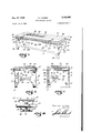
- Fig. 1 is a perspective view of a preferred embodiment of my invention.
- Fig. 2 is a plan view of Fig. 1 with the platform thereof removed.
- Fig. 3 is a sectional view taken substantially as indicated by the line 3-3 of Fig. 2.
- Fig. 4 is a sectional view taken substantially as indicated by the line 4-4 of Fig. 3.
- Fig. 5 is a sectional view taken as indicated by the line 5-5 of Fig, 3.
- Fig. 6 is an enlarged sectional view taken as indicated by the line 6-6 of Fig. 3.
- Fig. 7 is an enlarged sectional view taken as indicated by the line of Fig. 3.
- Fig. 8 is an enlarged fragmentary sectional view taken as indicated by the line 8-8 of Fig. 3.
- Fig. 9 is an enlarged fragmentary sectional view taken as indicated by the line 9-9 of Fig. 8.
- Fig. 10 is .an enlarged partly sectioned face view of one of the carriages, taken as indicated by the arrow H) of Fig. 4.
- the therapeutic device includes a general supporting means consisting of a base Ill having front and rear walls H and i2 and end walls I3 disposed in vertical planes, these walls being joined at corners which project downward so as to form legs M for engagement with the floor.
- the base It has top walls 15 and it, best shown in Figs. 2 and 3.
- These top walls I5 and I6 coopmeans of four carriages 22 which engage these:
- bracket 23 having a vertical outer wall 24, an upper shelf or horizontal walltlii and' The upperoportiona. of the vertical walls 24 and the upper horizontal walls25 of the brackets23 are secured. to the edges a lower horizontal wall 23.
- thistranslatable wall.portion-.sa comprisesiappad 39 having a longitudinal: channele 40v corresponding. to. the spinous processes: when the. patient .lies supine upon the platform: in proper. alignment with the pads39.. Below .-the..pad 39,1 and: attachedathereto, the translatable wall portion-38: has transverse cleats .4! in. side byl siderelationlontthe upper face of a belt 42 which extends-longitudinally of the.
- opening; 3 3 and: is .of such width that its. edges will engage theshel-ves STand -therebyJimitKthe downward. movement; of the translatable. wall portion-38L
- the belt 42;. as-shownlin-Fig. 3, has its front end 43 secured .totheplate 34 [adjacent theheadend' ofltheopenings3 3l The opposite, or foot endlMis attached .to. tension. springs 45-. for
- Theinternal mechanism .of the device. includes a vertically movable supportingm'ember d6 having-the general characteristics of a. lever, .it' beingconnected'at 'one endbyhinges 41 to the end walll'3iat the-foot ofthe device so that the head enddfl of the supporting member 46may move 4 vertically.
- the head end 48 of the vertically movable member 46 rests on springs 49 of barrel-type.
- the lower ends of the springs 49 rest upon a plate 56 which is vertically adjustable for the purpose of varying the action of the springs G9, as will be hereinafter explained.
- the plate 59 includes a threaded boss 5
- the upper portion of the shaft 53 has fixed thereorrabevel gear 56 engaged by a bevel pinion 51whichisfixed on the inner end of the shaft 58.
- the shaft 58 projects through the front wall ll of-the 'baselll and has thereon a hand wheel 59, rotation -of which hand wheel 59 will rotate the shaft 53 and produce vertical movement of the plate 53.
- abent arm 62 Fig. '7'; islextend'ed lfrom the plate to a belt63'which' runs over vertically, spaced pulleys 64"and-..65'.
- Theupper pulley Glisfixed on a shaft'65"which projects ..through .the .front wallll l'of thebase l-Oandl has thereon :an indicator. or pointer.
- 61 aolaptedato-v traverse a dial plate 68. on the front face ofl'the front wall" I I.
- The-lower pulley 65' rotates. ona fixed shaft 39..
- a-JnQtor-I'L- A smaller driversprocketlaaotthe gear unit-l6 through a: chain l9 drives.
- the. lever 81 comprises an undercut channel 89 forming a guide for a block- BIJWhich-is moved-up anddown the channelBQ-by a screw!!! which lies inthechannel89l
- projects belowthe lowen end. of the lever 3i and hasthereon a-handleQZ whereby. it-may, be rotated.
- the block BiL hasa projecting-pin portion 93. to. receive one end. of a link-.94,. the head end of which isconnectedbymeans of pin. 95..and a bracket96ito..thelower.face of the plate34 of the platform 2
- a sheave 99 carrying an eccentric weight I09 For the purpose of transmitting vibration through the pad 39 to the patient I support on the member 46 near the head end thereof a sheave 99 carrying an eccentric weight I09.
- a small variable speed electric motor IOI drives the sheave 99 through a belt I02.
- the relatively high frequency vibration produced by the eccentric rotation of the weight I99 is transmittedthrough the member 46 and the lobular member I0 to the vertically translatable wall portion 39 of the platform 2I and is thereby imparted 'to the tissuesv of the patient which contact the pad 99.
- carries a plurality of heating elements I05 of insulated resistance type. These heating elements I05 are placed in the upholster-- ing of the platform 2
- the wiring to theelectrical parts of the device has not been shown since conventional practices are followed.
- the control switches, etc. are all conveniently located on the front wall of the base as shown in Fig. 1.
- a timing switch I06 is provided, making it possible for the technician to place the patient under treatment which will be discontinued at the end of the period of time for which the timing switch I96 has been set.
- a switch I01 is provided for the vibrator drive motor l9l, which switch is in series with a rheostat I09 whereby the speed of the motor IOI may be varied.
- the motor 11 is of constant speed reversible type and for its operation, a main switch H0 and a reversing switch III are provided.
- the lobular member '10 has a plurality of lobes II5 equally spaced and of such width that they will pass between the shelves 31, as shown in Fig. 6. As the member I0 is rotated, these lobes I I5 apply upward pressure impulses to the translatable wall portion 38. However, it is not intended that these impulses be sudden or abrupt in their action, but preferably that they shall be modulated.
- the lobes I I5 pressupwardly against the lower face of the belt 92 of the translatable member 38 with a force or pressure depending upon the position of the plate 59 which supports the lower ends of the springs 49.
- the head end 49 of the movable supporting member 99 is carried on the upper ends of the springs 49 and the downward reaction of the lobes H5 against the translatable wall portion 99 tends to force the member downward so as to compress the springs 49. Conversely, therefore, the strength of the pressure applications of the lobes H5 in the translatable wall portion 39 will depend upon the position of the plate 59.
- the lobes I I 5 do not apply a simple vertical movement to the member 98, but instead produce rhythmic waves in the member 38 which are transmitted to the contacting portion of the patients body.
- the member I0, Fig. 3 is rotating in counterclockwise direction
- a lobe II5 moves upward and leftward from the position II5a thereof toward the position in which it is shown in full lines
- it will elevate that portion of the translatable wall 38 disposed directly thereabove', as indicated by dotted lines I20.
- This hump or wave I20 will travel leftward as the lobe travels from the position I 15a toward the position in which it is shown 1 in full lines.
- each pressure application from the pad 39 to the patient consists of a wave which arises at one point, travels longitudinally and then subsides.
- Such wave produces a beneficial massaging action, and such wave
- the wave motion A further feature of the device for use in making spinal adjustments.
- the patient When so used, the patient is placed in prone position with the crest of the raised pad 99 engaging the anterior portion of the patient opposite a point along the spine slightly interior to the subluxation which is to be corrected. The patient is then properly supported for an effective adjustment, but the support is yieldable due to the fact that the yielding of the springs 49 will permit a yielding of the translatable wall portion 38 of the platform 2 I.
- the length of movement of the platform 2i determines the length of the area of the patients body which will be subjected to the rhythmic wave motion of the pad 39 when the device is in operation.
- the block is raised on the lever 81 to its fullest extent, as shown in Fig. 3, maximum longitudinal movement of the platform 2
- a therapy device of the character described, the combination of: supporting means; a patient receiving platform carried by said supporting means, said platform having a portion which is translatable in vertical direction;
- pressure means for applying upward pressure waves to a limited portion of said translatable portion of said platform; means for locally applying heat to the patient on said platform in such manner as to heat body portions positioned adjacent said translatable portion of the platform; and means for relatively moving said platform and said pressure means whereby different por- :aeeauoe tions of :said translatable portion will .bevrnoved verticall-ybyrsaid pressure means to 'act -on the heated body portions.
- a therapy device of the character described, the combination of: supporting means; a :patient receiving platform carried by said supporting means, said platform having a portion which is translatable in vertical direction; pressure means for applying upward pressure impulses of relatively low frequency to a limited portion of said-translatable portion-of saidplatform; means for applying impulses of relatively high frequency to said platform; means for varying the intensity of said relatively low frequency impulses; means for varying the intensity of said ;relatively high frequency impulses; and means for relatively 'movin said platform and said pressure means whereby different .portions of said translatable portion will be moved by said pressure means.
- a therapy device 'of the character described, the combination of supporting means; a patient receiving platform carried by said supporting means, said platform having a portion which is translatable in vertical direction; pressure means for applying upward pressure impulses of relatively low frequency to a limited portion 'of said translatable portion of said platform; means for applying -impulses of relatively high frequency to said platform; means for varying the intensity of said relatively low frequency impulses; and means for relatively moving said platform and said pressure means whereby different portions of said translatable portion will be raised by said pressure means.
- a therapy device of the character described, "the combination of: supporting means; a patient receiving platform “carried by said supportin means, said platform having a portion which is translatable in vertical direction; pressure means for applying upward pressure impulses of relatively low frequency to a limited portion of said translatable portionof said platform; means acting through said pressure means for applying impulses of relatively high frequency to said platform;rmeans for varying the intensity of said relatively low frequency impulses; and means for varying the intensity of said relatively high frequency impulses.
- a therapy device of the character described, the combination of: supporting means; a patient receiving platform carried by said supporting means, said platform having a portion which is translatable in vertical direction; pressure means for applying upward pressure waves of relatively low frequency to a limited portion of said translatable portion of said platform; and means acting through said pressure means for applying impulses -of relatively high frequency to said platform.
- apatient .receivingplatform carried by said supporting unean's, said-platform having a portion which is translatable in vertical :direction; a supporting member carried byisaid-supporting means under saidiplatform; means for resiliently urging said supporting member upwardly toward said platform; a :lobular member rotatably supported on said supporting member; and means for rotating-said lobular member so that the lobes thereof will engage and liftisaid translatable portionzof said platform.
- a therapy device of the character described, Ithe combination 'of supporting means; a patient receiving platform-carried -by said supporting means, 'said”platform having a portion which is 'trans'latablein a vertical direction; a supporting member carried by said supporting means under said platform; spring means for resiliently urging :said supporting member upwardly toward said platform; translating means on said supporting member operative to intermittently apply upward movement to said translatableportion'of said platform; adjusting means for varyin'gthe stress in said spring means whereby the upward jpressureof said translating means against said translatable portion may be varied; and means. foryfbrating said supporting member wherebyvibr'ation willbe transmitted through said translating means to said translatable portion.
Landscapes
- Health & Medical Sciences (AREA)
- Epidemiology (AREA)
- Pain & Pain Management (AREA)
- Physical Education & Sports Medicine (AREA)
- Rehabilitation Therapy (AREA)
- Life Sciences & Earth Sciences (AREA)
- Animal Behavior & Ethology (AREA)
- General Health & Medical Sciences (AREA)
- Public Health (AREA)
- Veterinary Medicine (AREA)
- Orthopedics, Nursing, And Contraception (AREA)
Description
Dec. 27, 1949 R. THOMAS PHYSIOTHERAPY DEVICE 5 Sheets-Sheet 1' Filed July 9, 1946 W my X w w m x Aw/mep 77/0/1445,
IN V EN TOR.
Dec. 27, 1949 R. THOMAS 2,492,406
PHYSIOTHERAPY DEVICE Filed July 9, 19 46 5 Sheets-Sheet 2 m v mm DEC. 27, R THOMAS PHYSIOTHERAPY DEVICE 3 Sheets-Sheet 5 Filed July 9, 1946 Rwy/4 4 0 72/0/1445,
INVENTOR. 14
Patented Dec. 27, 1949 UNITED STATES PATENT OFFICE PHYSIOTHERAPY DEVICE Richard Thomas, Westwood Village, Calif.
Application July 9, 1946, Serial No. 682,412
(01. 12s-ss) 11 Claims.
My present invention relates to a device for treating the human body, having a table or platform on which the patient lies with the portion of the body to be treated presented downwardly so that the treating portion of the device carried by or forming a part of the platform may act upwardly against the portion of the patients body to be treated.
It is an object of the invention to provide a novel cooperation of parts in a single device H whereby several cooperating modalities may be effectively applied to the bod either simultaneously or separately. 7 By use of the device rhythmic pressure waves of predetermined intensity may be applied to selected tissues of the body, and to these selected tissues vibratory waves or motion may be transmitted, of intensity determined by the operator of the device. The device is so arranged that during the application of either or both the rhythmic and vibratory waves, infra-red radiations may be applied.
A further object of the invention is to provide a therapy device having a base with a platform or table thereon, this platform having a portion which is translatable vertically with relation to the rest of the platform, so that this vertically translatable portion may be moved upwardl in engagement with a selected portion of the body, and pressure applying means below the platform adapted to apply through the vertically translatable portion of the platform to the patient controlled pressure waves of low frequency and high frequency determinable from the needs of the patient.
A further object or the invention is to provide in a device of the character set forth in the preceding paragraph means for producing relative horizontal movement of the platform and the pressure applying means so that different portions of the translatable portion may be acted on by the pressure applying means of the device.
A further object of the invention is to provide a device of this character wherein this relative movement of the platform and the pressure applying means may be controlled as to length or extent, thereby making it possible to concentrate the treatment at one point or to extend the treatment over a selected linear portion of the body. For example, with the patient supine upon the platform and the back of the patient resting upon the vertically translatable pad portion, the treatment may be limited to the lumbo-sacral articulations, may be extended from below the sacrum to the dorsal region, may be concentrated in the lower dorsal or upper lumbar region, or may be 2 limited to the upper dorsal region. Also, with the patient lying prone, the treatment may be limited to the abdominal region and the pressure waves may be caused to press either headward or footward. When the lateral tissues of the body are to be treated, the patient lies on his side.
A further object of the invention is to provide simple adjusting means for the operative parts of the device whereby the rhythmic and vibratory waves transmitted to the patient may be controlled so that they may range from extremely mild to full intensity, and whereby the application of the therapy may be caused to correspond to the size or extent of the area to be treated.
Further objects and advantages of the invention reside in a simple arrangement of parts whereby the platform may be moved on the supporting structure of the table and whereby the operative mechanism below the platform is yieldably and adl'ustably supported.
Further objects and advantages of the invention may be brought out in the following part of the specification.
Referring to the drawings which are for illustrative purposes only,
Fig. 1 is a perspective view of a preferred embodiment of my invention.
Fig. 2 is a plan view of Fig. 1 with the platform thereof removed.
Fig. 3 is a sectional view taken substantially as indicated by the line 3-3 of Fig. 2.
Fig. 4 is a sectional view taken substantially as indicated by the line 4-4 of Fig. 3.
Fig. 5 is a sectional view taken as indicated by the line 5-5 of Fig, 3.
Fig. 6 is an enlarged sectional view taken as indicated by the line 6-6 of Fig. 3.
Fig. 7 is an enlarged sectional view taken as indicated by the line of Fig. 3.
Fig. 8 is an enlarged fragmentary sectional view taken as indicated by the line 8-8 of Fig. 3.
Fig. 9 is an enlarged fragmentary sectional view taken as indicated by the line 9-9 of Fig. 8.
Fig. 10 is .an enlarged partly sectioned face view of one of the carriages, taken as indicated by the arrow H) of Fig. 4.
As shown in the drawings, the therapeutic device includes a general supporting means consisting of a base Ill having front and rear walls H and i2 and end walls I3 disposed in vertical planes, these walls being joined at corners which project downward so as to form legs M for engagement with the floor. At the ends thereof the base It has top walls 15 and it, best shown in Figs. 2 and 3. These top walls I5 and I6 coopmeans of four carriages 22 which engage these:
portions of the rails I? which extend over the recesses [9 in the front and rear wal'fsl-I mid -I2? As shown in Figs. 4 and lllaeachrcarriage.22
comprises a bracket 23 having a vertical outer wall 24, an upper shelf or horizontal walltlii and' The upperoportiona. of the vertical walls 24 and the upper horizontal walls25 of the brackets23 are secured. to the edges a lower horizontal wall 23.
of. .the platform 21; In the spia'c'ezl betwee'ntth'e upper and lower horizontal walls- 251and2'6 of eachbracket 23"uppe'r and"lower.' rollers 28and 29are supported respectively by upperiand lower pillow blocks 30and3liinsuch' position th'atithe rollers ZBand i29'will'engage the upper andil'ower surfaces of the adjacent portions of the rails 11. The lower pillowblbck 3 Us SUDDOIItGGTOn rubber bodies.:-or washers 32"which actin expansion to pressthe' lower roller ZS'tigh'tIy against therail I llsothaflvibratihnof the .carriages relatively. to the. rails. Il ispreVent'edL It will be. perceived that the circumferential; faces. of the rollers 28 andl29' are concave. tdcorrespondlto .the external curvature ofltherails HTwhich are made from met'al..=tubing.,
As-shown in Figs- 3 to. '7 inclusive,.the. platformil. comprises ahorizontal plate 311 and padded upholsteringi.35.1covering. the. same.v and circumscribing: the opening, 33; Asshownin Figs. .3L and- 6,- metal strips 3fivareesecureclvtov the underface of the plate 34 of the pla-tformnzl alongpthe-lateral edgesHo-f theppening 33; portions of these plates 36 proiectingeunder the edges. of-.-.the. openinge33aso= as to. provide shelves 31. The platform 2| includes-a vertically translatable: wall- -p0Iti0nr:38-W-hi0h occupies= the opening 33. As shown in Figs. 1 .and--6,- thistranslatable wall.portion-.sa comprisesiappad 39 having a longitudinal: channele 40v corresponding. to. the spinous processes: when the. patient .lies supine upon the platform: in proper. alignment with the pads39.. Below .-the..pad 39,1 and: attachedathereto, the translatable wall portion-38: has transverse cleats .4! in. side byl siderelationlontthe upper face of a belt 42 which extends-longitudinally of the. opening; 3 3 and: is .of such width that its. edges will engage theshel-ves STand -therebyJimitKthe downward. movement; of the translatable. wall portion-38L The belt 42;. as-shownlin-Fig. 3, has its front end 43 secured .totheplate 34 [adjacent theheadend' ofltheopenings3 3l The opposite, or foot endlMis attached .to. tension. springs 45-. for
the. purpose of holding; the belt tight I and. permitting yieldabil'ity when. aportion of .thetranslatable. wall portion 38; is. raised,l. as.v shown in Fig 3.. The cleats. 4| permit longitudinal .bending. of .thetranslatable wallportion, but prevent lateral bending. thereof.
Theinternal mechanism .of the device. includes a vertically movable supportingm'ember d6 having-the general characteristics of a. lever, .it' beingconnected'at 'one endbyhinges 41 to the end walll'3iat the-foot ofthe device so that the head enddfl of the supporting member 46may move 4 vertically. The head end 48 of the vertically movable member 46 rests on springs 49 of barrel-type. The lower ends of the springs 49 rest upon a plate 56 which is vertically adjustable for the purpose of varying the action of the springs G9, as will be hereinafter explained. The plate 59 includes a threaded boss 5| which receives the threaded lower end 52, Fig. '7, of a vertical shaft 53 whiohlextends through amopening 54 in the head end aofi'the supporting member 46 and is hung from a thrust bearing 55, carried by the top wall Is at the head end of the base E9.
The upper portion of the shaft 53 has fixed thereorrabevel gear 56 engaged by a bevel pinion 51whichisfixed on the inner end of the shaft 58.
The shaft 58 projects through the front wall ll of-the 'baselll and has thereon a hand wheel 59, rotation -of which hand wheel 59 will rotate the shaft 53 and produce vertical movement of the plate 53. The upper and lower ends of the springs Q'Qare guided by. vertical bars 39', the lower ends of'whi'ch arei threaded into the end'portions of the plate 59'," ancl'the' upper. ends of whichare slidable through openings in the t'ransversebar 6i comprisingla portionof the headiendi48of the supporting member 46'.
To indicate the compressive forceeoractionof the springs 49 during. the operationof the device, abent arm 62, Fig. '7'; islextend'ed lfrom the plate to a belt63'which' runs over vertically, spaced pulleys 64"and-..65'. Theupper pulley Glisfixed on a shaft'65"which projects ..through .the .front wallll l'of thebase l-Oandl has thereon :an indicator. or pointer. 61 aolaptedato-v traverse a dial plate 68. on the front face ofl'the front wall" I I.
The-lower pulley 65'rotates. ona fixed shaft 39..
Themeansemployed forapplicationof. intermittent upward .force or pressure. waves .of. rela tively low: frequency to the translatable wall portion 38'comprisesa lobulanmember l0 fixed on a shaft 1Lwhichis.supportedinbearings 12. on the-vertically movable member. 461- Asprocket l3, fixed onthefront endof the shaft i -l, isdriven by a chain l4rfrom-aldrive sprocket .l S-cOmprising a.-.part.oflthe power. outputmecha-nism of. areduction. gear. unit- 16-: which. issalso mounted on the member 461and is driven by. a-JnQtor-I'L- A smaller driversprocketlaaotthe gear unit-l6 through a: chain l9 drives. a larger. sprocket I so carried. by a.shaft 81- which is supportedon the member lfiknean its-foot end lby blocks 82. A crank pin..83, .fixed on the sprocket is connected by a link 84 with a pin 85 mountedaona luge86 which projects laterally from .alever. 81 which,- as shown in .Fig=. .5, swings-:on. a. stub. shaft 88 supported on theinner. face-:of the front wall l l. near its-lower. edge. Asv shownin Figs. 8 and 9, the. lever 81 comprises an undercut channel 89 forming a guide for a block- BIJWhich-is moved-up anddown the channelBQ-by a screw!!! which lies inthechannel89l Thelower endof the-screw 9| projects belowthe lowen end. of the lever 3i and hasthereon a-handleQZ whereby. it-may, be rotated. The block BiLhasa projecting-pin portion 93. to. receive one end. of a link-.94,. the head end of which isconnectedbymeans of pin. 95..and a bracket96ito..thelower.face of the plate34 of the platform 2|, as shown .in Fig. 6.. Rotation of the sprocket 8D transmitsthrough thelink 84 reciprofcatinglmotion totheleveril]. When the block Si) lines 91 and 9B in Fig. 3. Accordingly, the relative movement of the platform 2! and the force applying means represented by the lobular member I0 may be controlled by operating the handle 92 so as to screw the block 90 to the desired position along the lever 81.
For the purpose of transmitting vibration through the pad 39 to the patient I support on the member 46 near the head end thereof a sheave 99 carrying an eccentric weight I09. A small variable speed electric motor IOI drives the sheave 99 through a belt I02. The relatively high frequency vibration produced by the eccentric rotation of the weight I99 is transmittedthrough the member 46 and the lobular member I0 to the vertically translatable wall portion 39 of the platform 2I and is thereby imparted 'to the tissuesv of the patient which contact the pad 99.
The platform 2| carries a plurality of heating elements I05 of insulated resistance type. These heating elements I05 are placed in the upholster-- ing of the platform 2| around the opening 93. By this arrangement it is possible to transmit heat radiations in the infra-red rays to the body of the patient. The wiring to theelectrical parts of the device has not been shown since conventional practices are followed. The control switches, etc., are all conveniently located on the front wall of the base as shown in Fig. 1. A timing switch I06 is provided, making it possible for the technician to place the patient under treatment which will be discontinued at the end of the period of time for which the timing switch I96 has been set. A switch I01 is provided for the vibrator drive motor l9l, which switch is in series with a rheostat I09 whereby the speed of the motor IOI may be varied. The motor 11 is of constant speed reversible type and for its operation, a main switch H0 and a reversing switch III are provided.
The lobular member '10 has a plurality of lobes II5 equally spaced and of such width that they will pass between the shelves 31, as shown in Fig. 6. As the member I0 is rotated, these lobes I I5 apply upward pressure impulses to the translatable wall portion 38. However, it is not intended that these impulses be sudden or abrupt in their action, but preferably that they shall be modulated. The lobes I I5 pressupwardly against the lower face of the belt 92 of the translatable member 38 with a force or pressure depending upon the position of the plate 59 which supports the lower ends of the springs 49. The head end 49 of the movable supporting member 99 is carried on the upper ends of the springs 49 and the downward reaction of the lobes H5 against the translatable wall portion 99 tends to force the member downward so as to compress the springs 49. Conversely, therefore, the strength of the pressure applications of the lobes H5 in the translatable wall portion 39 will depend upon the position of the plate 59. In other words, if the plate is raised, thereaction of the lobes H5 against the belt 42 will produce a greater compression of the springs 49 when the reaction "of the lobes II5 forces the supporting member 49 downward, and this greater compression of the springs 49 is determinative of the upward pressure of the lobes I I5 to raise the translatable wall portion 39 in a manner such as shown in Figs. 1, 3, and 6.
One of the features of the invention is that the lobes I I 5 do not apply a simple vertical movement to the member 98, but instead produce rhythmic waves in the member 38 which are transmitted to the contacting portion of the patients body. For example, assuming that the member I0, Fig. 3, is rotating in counterclockwise direction, when a lobe II5 moves upward and leftward from the position II5a thereof toward the position in which it is shown in full lines, it will elevate that portion of the translatable wall 38 disposed directly thereabove', as indicated by dotted lines I20. This hump or wave I20 will travel leftward as the lobe travels from the position I 15a toward the position in which it is shown 1 in full lines. Then, as leftward movement of the lobe continues across the lower face of the belt 42, the wave will move toward and into the position indicated by dotted lines I I517 and thereafter will subside. Accordingly, each pressure application from the pad 39 to the patient consists of a wave which arises at one point, travels longitudinally and then subsides. Such wave produces a beneficial massaging action, and such wave The wave motion A further feature of the device for use in making spinal adjustments. When so used, the patient is placed in prone position with the crest of the raised pad 99 engaging the anterior portion of the patient opposite a point along the spine slightly interior to the subluxation which is to be corrected. The patient is then properly supported for an effective adjustment, but the support is yieldable due to the fact that the yielding of the springs 49 will permit a yielding of the translatable wall portion 38 of the platform 2 I.
The length of movement of the platform 2i determines the length of the area of the patients body which will be subjected to the rhythmic wave motion of the pad 39 when the device is in operation. When the block is raised on the lever 81 to its fullest extent, as shown in Fig. 3, maximum longitudinal movement of the platform 2|. is obtained and the specific wave and/or vibratory therapy of the device will .traverse an area of the patient I30, shown on the device, from the hip region to the lower ,margin of the axilla.
When the block 90 is lowered from the position in which it is shown in Figs. 3 and 8 to the position at the lower end of the channel 89 wherein the axis of the pin portion 93 will be aligned with the axis of the member 88 on which the lever swings, the platform 2| will remain stationary and there will be no progressive shifting of the area of application of the waves to the body, thereby providing spot treatment instead of extended treatment.
I claim as my invention:
1. In a therapy device of the character described, the combination of: supporting means; a patient receiving platform carried by said supporting means, said platform having a portion which is translatable in vertical direction;
pressure means for applying upward pressure waves to a limited portion of said translatable portion of said platform; means for locally applying heat to the patient on said platform in such manner as to heat body portions positioned adjacent said translatable portion of the platform; and means for relatively moving said platform and said pressure means whereby different por- :aeeauoe tions of :said translatable portion will .bevrnoved verticall-ybyrsaid pressure means to 'act -on the heated body portions.
2.-In a therapy device of the character described, the combination of supportin means; "a patient receiving platform carried by said supporting means, said {platform having a portion which is translatable in vertical :direction; pressure means forrapp'lying upward intermittent impulses to a limited portion of said translatable portion of said Z-platform; and means for relatively moving said platform and said =pressure means in timed relation lengthwise of said platform wherebydiiferentportions of said'translatable portion will be moved by said pressure means.
3. *In a therapy device of the character described, the combination of: supporting means; a :patient receiving platform carried by said supporting means, said platform having a portion which is translatable in vertical direction; pressure means for applying upward pressure impulses of relatively low frequency to a limited portion of said-translatable portion-of saidplatform; means for applying impulses of relatively high frequency to said platform; means for varying the intensity of said relatively low frequency impulses; means for varying the intensity of said ;relatively high frequency impulses; and means for relatively 'movin said platform and said pressure means whereby different .portions of said translatable portion will be moved by said pressure means.
i. In a therapy device 'of the character de scribed, the combination of supporting means; a patient receiving platform carried by said supporting means, said platform having a portion which is translatable in vertical direction; pressure means for applying upward pressure impulses of relatively low frequency to a limited portion 'of said translatable portion of said platform; means for applying -impulses of relatively high frequency to said platform; means for varying the intensity of said relatively low frequency impulses; and means for relatively moving said platform and said pressure means whereby different portions of said translatable portion will be raised by said pressure means.
5. In a therapy device of the character described, "the combination of: supporting means; a patient receiving platform "carried by said supportin means, said platform having a portion which is translatable in vertical direction; pressure means for applying upward pressure impulses of relatively low frequency to a limited portion of said translatable portionof said platform; means acting through said pressure means for applying impulses of relatively high frequency to said platform;rmeans for varying the intensity of said relatively low frequency impulses; and means for varying the intensity of said relatively high frequency impulses.
6. In a therapy device of the character described, the combination of: supporting means; a patient receiving platform carried by said supporting means, said platform having a portion which is translatable in vertical direction; pressure means for applying upward pressure waves of relatively low frequency to a limited portion of said translatable portion of said platform; and means acting through said pressure means for applying impulses -of relatively high frequency to said platform.
:In a .therapyrlevice :of the @chara'cter described, thecombi-nation of: supporting means;
apatient .receivingplatform carried by said supporting unean's, said-platform having a portion which is translatable in vertical :direction; a supporting member carried byisaid-supporting means under saidiplatform; means for resiliently urging said supporting member upwardly toward said platform; a :lobular member rotatably supported on said supporting member; and means for rotating-said lobular member so that the lobes thereof will engage and liftisaid translatable portionzof said platform.
8. Ina therapy device of the character 'described, the combination of: supporting means; a patient receivingplatform carried by said supporting means, said plat-form having a portion which is translatable in -a vertical direction; a supporting :member carried by said supporting means under said :pla-tform; spring means for resiliently urging said supporting member upwardly toward said platform; translating means *ons'a'id supportingimemberoperativeto intermittently apply upward movement "to said translatable portion of said platform; :and adjusting means for varying the stress 'in said spring means whereby the upward pressure of said translating means against said "translatable portion may be varied.
9; In a therapy device :of the character described, Ithe combination 'of supporting means; a patient receiving platform-carried -by said supporting means, 'said"platform having a portion which is 'trans'latablein a vertical direction; a supporting member carried by said supporting means under said platform; spring means for resiliently urging :said supporting member upwardly toward said platform; translating means on said supporting member operative to intermittently apply upward movement to said translatableportion'of said platform; adjusting means for varyin'gthe stress in said spring means whereby the upward jpressureof said translating means against said translatable portion may be varied; and means. foryfbrating said supporting member wherebyvibr'ation willbe transmitted through said translating means to said translatable portion.
'10. 'In a therapy "device 'of the character described, the-combination of: supporting means; a'patient receiving platform carried by said supportingmean's; pressure applying means under saidp'la'tform for interniitte'ntly'applying upward pressure; and means "for horizontally moving said platform relatively 'to said pressure applying means pom-prising a lever hinged at one end, means "for sw irfg in'g said lever back and forth, a link having one end thereof connected to said platform, and means for ccnnecting the other end *of said lirik-seletitively to 'points along said lever.
mgmea'ns' RICHARD THOMAS.
(Referenceson following page) REFERENCES CITED Number Name 1 Date 1,643,039 Wentz se t. 20, 1927 g figg ggf fff are m the 1,643,399 Wentworth Sept. 27, 1927 1,874,286 Gross Aug. 30, 1932 UNITED STATES PATENTS 5 2,175,614 Redfield Oct. 10, 1939 Number Name Date 2,235,183 Wettlaufer Mar. 18, 19-11 94 73 Church 30 909 ,271,3 2 Worthington Jan. 27, 1942 1,004,300 Pope Sept. 26, 1911 2,284,445 qW May 1942 1,238, 91 Beuchler Aug. 28, 1917 2,374,492 Mmmberg Apr. 24, 1945 1,587,737 Trumbull June 8, 1926 10 2,448,777 Crise Sept. 7, 1943 1,638,025 Everts Aug. 9, 1927
Priority Applications (1)
| Application Number | Priority Date | Filing Date | Title |
|---|---|---|---|
| US682412A US2492406A (en) | 1946-07-09 | 1946-07-09 | Physiotherapy device |
Applications Claiming Priority (1)
| Application Number | Priority Date | Filing Date | Title |
|---|---|---|---|
| US682412A US2492406A (en) | 1946-07-09 | 1946-07-09 | Physiotherapy device |
Publications (1)
| Publication Number | Publication Date |
|---|---|
| US2492406A true US2492406A (en) | 1949-12-27 |
Family
ID=24739572
Family Applications (1)
| Application Number | Title | Priority Date | Filing Date |
|---|---|---|---|
| US682412A Expired - Lifetime US2492406A (en) | 1946-07-09 | 1946-07-09 | Physiotherapy device |
Country Status (1)
| Country | Link |
|---|---|
| US (1) | US2492406A (en) |
Cited By (14)
| Publication number | Priority date | Publication date | Assignee | Title |
|---|---|---|---|---|
| US2664882A (en) * | 1950-07-11 | 1954-01-05 | Thomas M Parker | Spinal massage apparatus |
| US2889826A (en) * | 1957-11-26 | 1959-06-09 | Benjamin J Russo | Massage machine |
| US2992044A (en) * | 1958-10-07 | 1961-07-11 | Johnson Forrest Gerald | Coin operated vibrating couch and ejector |
| US3003497A (en) * | 1959-02-25 | 1961-10-10 | John L Nunes | Massage table with hydraulically controlled roller |
| US3238936A (en) * | 1962-04-16 | 1966-03-08 | Nat Foundation For Physical Me | Apparatus for mechanical corrective therapy |
| DE1266447B (en) * | 1957-10-08 | 1968-04-18 | Owen Kenneth Murphy | Padded lying or sitting device with massage devices for the human body |
| US3880150A (en) * | 1973-11-08 | 1975-04-29 | Matthew J Vileikis | Therapeutic treatment machine |
| US3882856A (en) * | 1973-11-23 | 1975-05-13 | Gordon D Heuser | Therapeutic manipulating machine for the human body |
| US4503844A (en) * | 1983-01-13 | 1985-03-12 | Fischer Imaging Corporation | Surgical table |
| US4520800A (en) * | 1983-05-09 | 1985-06-04 | Standex International Corporation | Patient treatment table |
| EP0280487A2 (en) * | 1987-02-24 | 1988-08-31 | Kim Chae Yong | Back massager |
| US6190338B1 (en) * | 1998-10-05 | 2001-02-20 | Chattanooga Group, Inc. | Therapeutic massage table |
| WO2010126398A1 (en) | 2009-04-30 | 2010-11-04 | Larisa Semenovna Grigoreva | Method of passive mechanotherapy and exercise machine for implementation thereof |
| US20170258670A1 (en) * | 2014-07-29 | 2017-09-14 | Ricardo Miguel Kauffmann Sommella | Exerciser for regaining flexibility |
Citations (14)
| Publication number | Priority date | Publication date | Assignee | Title |
|---|---|---|---|---|
| US941673A (en) * | 1908-12-21 | 1909-11-30 | Electro Vibrating Couch Company | Electrovibratory couch. |
| US1004300A (en) * | 1910-12-16 | 1911-09-26 | Frank Pope | Massage apparatus. |
| US1238091A (en) * | 1917-07-23 | 1917-08-28 | John R Beuchler Jr | Flesh-reducing apparatus. |
| US1587737A (en) * | 1925-07-09 | 1926-06-08 | Willis H Trumbull | Spine-treating device |
| US1638025A (en) * | 1926-06-29 | 1927-08-09 | Sid Post | Exercising bed |
| US1643039A (en) * | 1925-09-22 | 1927-09-20 | Jere L Wentz | Massage machine |
| US1643399A (en) * | 1927-09-27 | Therapeutic apparatus | ||
| US1874286A (en) * | 1927-10-19 | 1932-08-30 | Gross Henry | Therapeutic device |
| US2175614A (en) * | 1939-04-10 | 1939-10-10 | William C Redfield | Massaging couch |
| US2235183A (en) * | 1939-05-11 | 1941-03-18 | William L Wettlaufer | Therapeutic vibrator |
| US2271382A (en) * | 1939-05-06 | 1942-01-27 | Ray W Worthington | Platform foot and body vibrator |
| US2284445A (en) * | 1940-07-27 | 1942-05-26 | Fred H Pettit | Therapeutic device |
| US2374492A (en) * | 1942-09-19 | 1945-04-24 | Nathan D Mininberg | Therapeutic apparatus |
| US2448777A (en) * | 1944-01-19 | 1948-09-07 | George W Crise | Massaging apparatus |
-
1946
- 1946-07-09 US US682412A patent/US2492406A/en not_active Expired - Lifetime
Patent Citations (14)
| Publication number | Priority date | Publication date | Assignee | Title |
|---|---|---|---|---|
| US1643399A (en) * | 1927-09-27 | Therapeutic apparatus | ||
| US941673A (en) * | 1908-12-21 | 1909-11-30 | Electro Vibrating Couch Company | Electrovibratory couch. |
| US1004300A (en) * | 1910-12-16 | 1911-09-26 | Frank Pope | Massage apparatus. |
| US1238091A (en) * | 1917-07-23 | 1917-08-28 | John R Beuchler Jr | Flesh-reducing apparatus. |
| US1587737A (en) * | 1925-07-09 | 1926-06-08 | Willis H Trumbull | Spine-treating device |
| US1643039A (en) * | 1925-09-22 | 1927-09-20 | Jere L Wentz | Massage machine |
| US1638025A (en) * | 1926-06-29 | 1927-08-09 | Sid Post | Exercising bed |
| US1874286A (en) * | 1927-10-19 | 1932-08-30 | Gross Henry | Therapeutic device |
| US2175614A (en) * | 1939-04-10 | 1939-10-10 | William C Redfield | Massaging couch |
| US2271382A (en) * | 1939-05-06 | 1942-01-27 | Ray W Worthington | Platform foot and body vibrator |
| US2235183A (en) * | 1939-05-11 | 1941-03-18 | William L Wettlaufer | Therapeutic vibrator |
| US2284445A (en) * | 1940-07-27 | 1942-05-26 | Fred H Pettit | Therapeutic device |
| US2374492A (en) * | 1942-09-19 | 1945-04-24 | Nathan D Mininberg | Therapeutic apparatus |
| US2448777A (en) * | 1944-01-19 | 1948-09-07 | George W Crise | Massaging apparatus |
Cited By (18)
| Publication number | Priority date | Publication date | Assignee | Title |
|---|---|---|---|---|
| US2664882A (en) * | 1950-07-11 | 1954-01-05 | Thomas M Parker | Spinal massage apparatus |
| DE1266447B (en) * | 1957-10-08 | 1968-04-18 | Owen Kenneth Murphy | Padded lying or sitting device with massage devices for the human body |
| US2889826A (en) * | 1957-11-26 | 1959-06-09 | Benjamin J Russo | Massage machine |
| US2992044A (en) * | 1958-10-07 | 1961-07-11 | Johnson Forrest Gerald | Coin operated vibrating couch and ejector |
| US3003497A (en) * | 1959-02-25 | 1961-10-10 | John L Nunes | Massage table with hydraulically controlled roller |
| US3238936A (en) * | 1962-04-16 | 1966-03-08 | Nat Foundation For Physical Me | Apparatus for mechanical corrective therapy |
| US3880150A (en) * | 1973-11-08 | 1975-04-29 | Matthew J Vileikis | Therapeutic treatment machine |
| US3882856A (en) * | 1973-11-23 | 1975-05-13 | Gordon D Heuser | Therapeutic manipulating machine for the human body |
| US4503844A (en) * | 1983-01-13 | 1985-03-12 | Fischer Imaging Corporation | Surgical table |
| US4520800A (en) * | 1983-05-09 | 1985-06-04 | Standex International Corporation | Patient treatment table |
| EP0280487A2 (en) * | 1987-02-24 | 1988-08-31 | Kim Chae Yong | Back massager |
| EP0280487A3 (en) * | 1987-02-24 | 1989-09-13 | Kim Chae Yong | Back massager |
| US6190338B1 (en) * | 1998-10-05 | 2001-02-20 | Chattanooga Group, Inc. | Therapeutic massage table |
| WO2010126398A1 (en) | 2009-04-30 | 2010-11-04 | Larisa Semenovna Grigoreva | Method of passive mechanotherapy and exercise machine for implementation thereof |
| EP2370042A1 (en) * | 2009-04-30 | 2011-10-05 | Larisa Semenovna Grigoreva | Method of passive mechanotherapy and exercise machine for implementation thereof |
| EP2370042A4 (en) * | 2009-04-30 | 2012-07-18 | Larisa Semenovna Grigoreva | Method of passive mechanotherapy and exercise machine for implementation thereof |
| US10912702B2 (en) | 2009-04-30 | 2021-02-09 | Larisa Semenovna Grigoreva | Method of passive mechanotherapy and exercise machine for implementation thereof |
| US20170258670A1 (en) * | 2014-07-29 | 2017-09-14 | Ricardo Miguel Kauffmann Sommella | Exerciser for regaining flexibility |
Similar Documents
| Publication | Publication Date | Title |
|---|---|---|
| US2492406A (en) | Physiotherapy device | |
| US2874689A (en) | Body exercising device | |
| US3316898A (en) | Rehabilitation and exercise apparatus | |
| US3835844A (en) | Apparatus for stretching the spine | |
| CN111012643B (en) | Distributed type local muscle spasm physical therapy device | |
| GB1326201A (en) | Therapeutic tables | |
| KR100769052B1 (en) | The abdominal massage apparatus | |
| US7311682B2 (en) | Massage table for adjusting spinal area | |
| US2273088A (en) | Massaging table | |
| GB1306642A (en) | Apparatus for stretching the spinal column | |
| KR101136724B1 (en) | Medical pressing device for human spine | |
| US2840072A (en) | Massage bed | |
| CN112402149A (en) | Joint bone injury medicine applying treatment device | |
| US3628528A (en) | Massaging and reducing machine | |
| US6695796B1 (en) | Chiropractic massage device | |
| US4886051A (en) | Massaging bed | |
| US3794018A (en) | Massage device | |
| KR101705239B1 (en) | Massage apparatus | |
| KR200313149Y1 (en) | Finger-pressure apparatus | |
| US2112367A (en) | Massaging apparatus | |
| CN105919788A (en) | Comfortable type medical shoulder massage device | |
| CN216629122U (en) | Physiotherapy robot with waist massage function | |
| KR20020082949A (en) | Medical Pressing Device for human Spine | |
| US2841139A (en) | Combined exercising and massaging lounge | |
| CN113995669A (en) | Physical therapy robot and control method thereof |