US20100220910A1 - Method and system for automated x-ray inspection of objects - Google Patents
Method and system for automated x-ray inspection of objects Download PDFInfo
- Publication number
- US20100220910A1 US20100220910A1 US12/395,761 US39576109A US2010220910A1 US 20100220910 A1 US20100220910 A1 US 20100220910A1 US 39576109 A US39576109 A US 39576109A US 2010220910 A1 US2010220910 A1 US 2010220910A1
- Authority
- US
- United States
- Prior art keywords
- dimensional
- dimensional reference
- reference model
- image
- idealized
- Prior art date
- Legal status (The legal status is an assumption and is not a legal conclusion. Google has not performed a legal analysis and makes no representation as to the accuracy of the status listed.)
- Abandoned
Links
Images


Classifications
-
- G—PHYSICS
- G06—COMPUTING; CALCULATING OR COUNTING
- G06T—IMAGE DATA PROCESSING OR GENERATION, IN GENERAL
- G06T7/00—Image analysis
- G06T7/0002—Inspection of images, e.g. flaw detection
- G06T7/0004—Industrial image inspection
- G06T7/001—Industrial image inspection using an image reference approach
-
- G—PHYSICS
- G06—COMPUTING; CALCULATING OR COUNTING
- G06T—IMAGE DATA PROCESSING OR GENERATION, IN GENERAL
- G06T2207/00—Indexing scheme for image analysis or image enhancement
- G06T2207/10—Image acquisition modality
- G06T2207/10116—X-ray image
Definitions
- the invention relates generally to nondestructive testing (NDT) of parts and more particularly to a method and system for automatically identifying defects in NDT image data corresponding to a scanned object.
- NDT nondestructive testing
- NDT is a technique of producing relevant data for an object by collecting energy emitted by or transmitted through the object, such as by penetrating radiation (gamma rays, X-rays, neutrons, charged particles, etc.) sound waves, or light (infrared, ultraviolet, visible, etc.).
- penetrating radiation gamma rays, X-rays, neutrons, charged particles, etc.
- the manner by which energy is transmitted through or emitted by any object depends upon variations in object thickness, density, and chemical composition.
- the energy emergent from the object is collected by appropriate detectors to form an image or object map, which may then be realized on an image detection medium, such as a radiation sensitive detector.
- a radiographic detector for example, comprises an array of elements that records the incident energy at each element position, and maps the recording onto a two-dimensional (2D) image.
- the 2D image is then fed to a computer workstation and interpreted by trained personnel.
- Non-limiting examples of NDT modalities include
- Radiography and other NDT inspection modalities find wide application in various medical and industrial applications as a non-destructive technique for examining the internal structure of an object.
- Non-destructive evaluation (NDE) of industrial parts is essential for manufacturing productivity and quality control.
- NDE Non-destructive evaluation
- radiographic images of aluminum castings are typically inspected by an operator who identifies defects pertaining to porosities, inclusions, shrinkages, cracks, etc. in the castings.
- the manual inspection procedure is often prone to operator fatigue and hence suffers from low inspection reliability.
- a number of NDT inspection techniques such as feature-based classification, artificial neural networks and adaptive filtering have been developed to perform automatic radiographic inspections of scanned objects. These techniques are typically based on using automated defect recognition (ADR) techniques to automatically screen images, call out defects and prioritize the ones needing visual inspection.
- ADR automated defect recognition
- ADR techniques typically achieve more accurate defect detection than human operators and have a much higher efficiency and consistency, thereby enhancing quality control in a wide variety of applications, such as, for example, automotive parts and engine components of aircraft, ships and power generators.
- Techniques using ADR may typically be used to perform automatic defect detection on 2D images and/or 3D images, based on analyzing the geometry (e.g., shape, size), feature (e.g., intensity, texture, color) and other local image statistics in the radiographic image data, to locate abnormalities.
- ADR techniques based on image features use a set of features to identify potential flaws in scanned object parts based on flaw morphology and gray level statistics. These techniques assign each pixel in the image into one of several classes based on minimizing a distance metric, wherein the parameters characterizing the distance metric are evaluated using a supervised learning scheme.
- an anomaly detection method for comparing a scanned object to an idealized object includes generating a three-dimensional reference model of the idealized object.
- the anomaly detection method further includes acquiring at least one two-dimensional inspection test image of the scanned object and determining a two-dimensional reference image from the three-dimensional reference model using multiple pose parameters estimated by a 3D-2D registration algorithm, wherein the two-dimensional reference image corresponds to the same view of the three-dimensional reference model of the idealized object as the view of the two-dimensional inspection test image of the scanned object.
- the anomaly detection method includes identifying one or more defects in the inspection test image via automated defect recognition technique.
- an inspection system in accordance with another embodiment of the invention, includes an imaging system configured to acquire inspection test image data corresponding to a scanned object.
- the inspection system further includes a computer system configured to be in signal communication with the imaging system.
- the computer system comprises a memory configured to store the inspection test image data corresponding to the scanned object, wherein the image data comprises at least one of an inspection test image of the scanned object and one or more reference images for the idealized object.
- the computer system further includes a processor configured to process the inspection test image data corresponding to the object.
- the processor is further configured to generate a three-dimensional reference model of the idealized object, receive the inspection test image data of the scanned object from the imaging system, determine a two-dimensional reference image from the three-dimensional reference model using multiple pose parameters estimated by a 3D-2D registration algorithm, and identify one or more defects in the inspection test image via automated defect recognition technique.
- the inspection system further includes a display device configured to display one or more defects in the inspection test image data corresponding to the scanned object.
- FIG. 1 is an illustration of an exemplary inspection system for automated X-ray inspection of three-dimensional objects.
- FIG. 2 is a flowchart illustrating an exemplary process for anomaly detection in accordance with aspects of the present technique.
- FIG. 3 depicts a schematic block diagram for generating a three-dimensional reference model.
- the present techniques are generally directed to automated anomaly detection, possibly in conjunction with computer assisted detection and/or diagnosis (CAD) algorithms.
- CAD computer assisted detection and/or diagnosis
- Such analysis may be useful in a variety of imaging contexts, such as industrial inspection system, nondestructive testing and others.
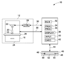
- FIG. 1 is an illustration of an exemplary inspection system for processing an inspection test image data corresponding to a scanned object.
- the inspection system 10 includes a computer system 14 adapted to be in signal communication with an imaging system 12 via a communication bus 30 .
- a real-time image controller 46 is adapted to be in signal communication with the computer system 14 via another communication bus 44 .
- the imaging system 12 is configured to acquire and output x-ray image data corresponding to a scanned object 18 via an imaging device 16 .
- the imaging system 12 may include, but is not limited to, an X-ray system, a CT system, an infra-red system, an eddy current system, an ultrasound system and an optical system.
- the imaging device 16 includes an X-ray source 22 , an image detector 24 and an object manipulator 26 .
- the imaging system 12 also includes an imaging system controller 28 that receives control commands from the computer system 14 and sends control signals to the various components of the imaging device 16 .
- the object manipulator 26 may be a conveyor belt, a reversible table, or any other suitable device for manipulating the scanned object 18 into and out of the X-ray beam 20 .
- the computer system 14 includes a memory 32 configured to store the X-ray inspection test image data corresponding to the scanned object 18 . Further, the memory 32 may include, but is not limited to, any type and number of memory chip, magnetic storage disks, optical storage disks, mass storage devices, or any other storage device suitable for retaining information.
- the computer system 14 also includes one or more processors 34 , 36 configured to process the X-ray inspection test image data corresponding to the scanned object.
- processor for performing the processing tasks of the invention.
- processor is intended to denote any machine capable of performing the calculations, or computations, necessary to perform the tasks of the invention.
- processor is intended to denote any machine that is capable of accepting a structured input and of processing the input in accordance with prescribed rules to produce an output.
- phrase “configured to” as used herein means that the processor is equipped with a combination of hardware and software for performing the tasks of the invention, as will be understood by those skilled in the art.
- the processor is further configured to generate a three-dimensional reference model of the idealized object.
- the processor further receives the inspection test image data of the scanned object from the imaging system and determines a two-dimensional reference image from the three-dimensional reference model using multiple pose parameters estimated by a 3D-2D registration algorithm, wherein the two-dimensional reference image corresponds to the same view of the three-dimensional reference model of the idealized object as the view of the two-dimensional inspection test image of the scanned object.
- the processor registers the three-dimensional reference model and the two-dimensional inspection test image of the scanned object and identifies one or more defects in the inspection test image via an automated defect recognition technique.
- the reference model consists of a 3D statistical model of both part density and part variation. Defects are found by statistically testing the 2D test image against both the registered and projected 2D reference image and labeling areas as defects that fall outside of normalcy probabilities. Further details of the automated defect recognition technique may be obtained in U.S. Pat. No. 4,896,278 entitled “AUTOMATED DEFECT RECOGNITION SYSTEM”, the entirety of which is hereby incorporated by reference herein.
- the computer system 14 also includes a detector interface card 42 , an input device 40 and a display device 38 .
- the input device 40 may include, but is not limited to, a keyboard, a mouse, a pointing device, a touch sensitive screen device, a tablet, a read/write drive for a magnetic disk, a read/write drive for an optical disk, a read/write drive for any other input medium, an input port for a communication link (electrical or optical), a wireless receiver.
- the display device 38 may be a CRT (cathode ray tube) screen or any other suitable display device for displaying text, graphics and a graphical user interface, for example.
- the display device is configured to display one or more defects in the X-ray inspection test image corresponding to the scanned object.
- the input device 40 and the display device 38 operate in combination to provide a graphical user interface, which enables a user or operator to configure and operate the radiographic inspection system 10 .
- the detector interface card 42 provides low-level control over the image detector, buffers data read out from the image detector 24 , and optionally reorders image pixels to convert from read-out order to display order.
- the real-time image controller 46 includes a set of image control buttons 50 , a set of image control dials 48 , a display 52 , and an embedded application programming interface that maps the functions of the control buttons and dials 48 , 50 to the computer system 14 .
- FIG. 2 illustrates a flowchart of an exemplary process 60 for anomaly detection of a scanned object through comparative analysis of the X-ray inspection test image to an idealized object.
- the defects may include, but are not limited to, casting and/or manufacturing defects present in a scanned object.
- the scanned object may include industrial parts, such as, for example, turbine engine components.
- the scanned object may also include, automotive parts such as, casting wheels, engine components, and shafts.
- Other non-limiting exemplary applications of the present anomaly detection process 60 may be in the manufacture of aircraft engine parts. During manufacturing of aircraft engine parts, variations are inevitable due to slight variations in the casting and processing steps.
- the process 60 comprises generating a three-dimensional reference model of the idealized object at step 62 .
- the idealized object may be referred to a defect free object or defect free objects having variations in geometric shape or a three-dimensional CAD model of a virtual defect free object.
- a two-dimensional inspection test image data corresponding to a scanned object is acquired.
- the inspection test image data comprises an X-ray image data and is acquired using an inspection system as described in FIG. 1 .
- Other examples of inspection image data include, without limitation, radiography, CT, infrared, eddy current, ultrasound and optical image data.
- multiple pose parameters are estimated by a 3D-2D registration algorithm to generate a two-dimensional reference image from the three-dimensional reference model.
- the multiple pose parameters may include rotational or translational parameters to incorporate any rotational or translational orientation of the scanned object to generate a two-dimensional reference image from the three-dimensional reference model.
- the two-dimensional reference image is determined by forward projection of the three-dimensional reference model. In another embodiment, the two-dimensional reference image is determined by simulation of x-ray imagine of the three-dimensional reference model.
- the two-dimensional reference image is registered to the two-dimensional inspection test image of the scanned object.
- the registration is performed so as to address the differences in the acquisition parameters between different imaging modalities.
- the process of registration which is also referred to as image fusion, superimposition, matching or merging, maps each point in one image onto the corresponding point in the second image.
- any registration method may be employed to register the images with one another before comparing the images for differences or changes. This includes fully automatic registration as well as computer assisted manual registration, or any registration approach using varying degrees of manual intervention.
- one or more defects in the inspection test image are identified via automatic defect recognition technique, which may comprise statistical evaluation, image differencing from a reference image, or pattern recognition for performing two-dimensional detection.
- FIG. 3 is a schematic block diagram 70 illustrating a specific embodiment for performing step 62 in FIG. 2 to generate a three-dimensional reference model 80 .
- the three-dimensional reference model 80 is generated from at least one reference three-dimensional image of the idealized object obtained via a computer tomography scan of a physical representation of the idealized object.
- the three-dimensional reference model is determined from a three-dimensional statistical reference model based on a statistical analysis of variations between multiple three-dimensional images of one or more physical representations of the idealized object, which is sufficiently highlighted in subsequent blocks 72 and 74 .
- the present invention sufficiently represents pre-processing of the part variations in 3D using a 3D statistical reference image and pre-processing of the manufacturing defects in 2D by comparing the 2D inspection test image to the projected or computed 2D reference image.
- the three-dimensional reference model is determined from a three-dimensional CAD model 78 of the idealized object.
- Embodiments of the present invention disclose a modeling technique to identify anomalies in inspection test image data corresponding to a scanned object, by generating a three-dimensional reference model and using 3D-2D registration and projection algorithms to determine a two-dimensional reference image to be compared to the inspection test image and applying the standard ADR techniques.
- the disclosed anomaly detection approach efficiently utilizes the system operation time by eliminating the steps of aligning the objects such as metal castings to be scanned in an assembly line.
- the three-dimensional reference modeling approach is robust to changes in object part geometry and misalignment of scanned object parts since it is built using a number of defect-free images that can automatically encode normal variations that occur due to part-to-part variations within manufacturing specifications and image-to-image variations that occur due to appearance changes and spatial misalignment.
- the present invention increases screening efficiency and consistency of inspection systems.
- the disclosed statistical modeling approach for detecting defects may be applied to multiple observations corresponding to multiple images of the scanned object acquired at one or more view angles.
- the various embodiments of the anomaly detection method and inspection system described above thus provide a way to achieve a convenient and efficient automatic identification of defects in NDT image data corresponding to a scanned object.
Abstract
An anomaly detection method and system for comparing a scanned object to an idealized object is provided. The anomaly detection method includes generating a three-dimensional reference model of the idealized object. The anomaly detection method further includes acquiring at least one two-dimensional inspection test image of the scanned object. The anamoly detection method also includes determining a two-dimensional reference image from the three-dimensional reference model using multiple pose parameters, wherein the two-dimensional reference image corresponds to the same view of the three-dimensional reference model of the idealized object as the view of the two-dimensional inspection test image of the scanned object. The anamoly detection method further includes identifying one or more defects in the inspection test image via automated defect recognition technique.
Description
- The invention relates generally to nondestructive testing (NDT) of parts and more particularly to a method and system for automatically identifying defects in NDT image data corresponding to a scanned object.
- NDT is a technique of producing relevant data for an object by collecting energy emitted by or transmitted through the object, such as by penetrating radiation (gamma rays, X-rays, neutrons, charged particles, etc.) sound waves, or light (infrared, ultraviolet, visible, etc.). The manner by which energy is transmitted through or emitted by any object depends upon variations in object thickness, density, and chemical composition. The energy emergent from the object is collected by appropriate detectors to form an image or object map, which may then be realized on an image detection medium, such as a radiation sensitive detector. A radiographic detector, for example, comprises an array of elements that records the incident energy at each element position, and maps the recording onto a two-dimensional (2D) image. The 2D image is then fed to a computer workstation and interpreted by trained personnel. Non-limiting examples of NDT modalities include X-ray, CT, infrared, eddy current, ultrasound and optical.
- Radiography and other NDT inspection modalities find wide application in various medical and industrial applications as a non-destructive technique for examining the internal structure of an object. Non-destructive evaluation (NDE) of industrial parts is essential for manufacturing productivity and quality control. For example, in aerospace and automotive industries, radiographic images of aluminum castings are typically inspected by an operator who identifies defects pertaining to porosities, inclusions, shrinkages, cracks, etc. in the castings. However, and as will be appreciated by those skilled in the art, owing to the structural complexity and large production volumes of these castings, the manual inspection procedure is often prone to operator fatigue and hence suffers from low inspection reliability.
- A number of NDT inspection techniques such as feature-based classification, artificial neural networks and adaptive filtering have been developed to perform automatic radiographic inspections of scanned objects. These techniques are typically based on using automated defect recognition (ADR) techniques to automatically screen images, call out defects and prioritize the ones needing visual inspection. As will be appreciated by those skilled in the art, ADR techniques typically achieve more accurate defect detection than human operators and have a much higher efficiency and consistency, thereby enhancing quality control in a wide variety of applications, such as, for example, automotive parts and engine components of aircraft, ships and power generators. Techniques using ADR may typically be used to perform automatic defect detection on 2D images and/or 3D images, based on analyzing the geometry (e.g., shape, size), feature (e.g., intensity, texture, color) and other local image statistics in the radiographic image data, to locate abnormalities. For example, ADR techniques based on image features use a set of features to identify potential flaws in scanned object parts based on flaw morphology and gray level statistics. These techniques assign each pixel in the image into one of several classes based on minimizing a distance metric, wherein the parameters characterizing the distance metric are evaluated using a supervised learning scheme. However, the performance of these techniques is affected by variations caused by object structure or flaw morphology and these techniques generally require large training sets with labeled flaws to perform defect identification. Additionally, a number of NDT techniques involving 3D scanning of objects and 3D image to 2D image registration, makes the process of anomaly detection slower and inefficient.
- It would therefore be desirable to develop an efficient NDT inspection technique for automatically detecting defects in the NDT image data corresponding to a scanned object. In addition, it would be desirable to develop an efficient NDT inspection technique that detects anomalies in industrial parts, produces accurate defect detection rates, increases the screening efficiency and consistency of inspection systems, efficiently utilizes system operation setup time and system training time and is robust to changes in object part geometry and misalignment of scanned object parts.
- In accordance with an embodiment of the invention, an anomaly detection method for comparing a scanned object to an idealized object is provided. The anomaly detection method includes generating a three-dimensional reference model of the idealized object. The anomaly detection method further includes acquiring at least one two-dimensional inspection test image of the scanned object and determining a two-dimensional reference image from the three-dimensional reference model using multiple pose parameters estimated by a 3D-2D registration algorithm, wherein the two-dimensional reference image corresponds to the same view of the three-dimensional reference model of the idealized object as the view of the two-dimensional inspection test image of the scanned object. Finally, the anomaly detection method includes identifying one or more defects in the inspection test image via automated defect recognition technique.
- In accordance with another embodiment of the invention, an inspection system is provided. The inspection system includes an imaging system configured to acquire inspection test image data corresponding to a scanned object. The inspection system further includes a computer system configured to be in signal communication with the imaging system. The computer system comprises a memory configured to store the inspection test image data corresponding to the scanned object, wherein the image data comprises at least one of an inspection test image of the scanned object and one or more reference images for the idealized object. The computer system further includes a processor configured to process the inspection test image data corresponding to the object. The processor is further configured to generate a three-dimensional reference model of the idealized object, receive the inspection test image data of the scanned object from the imaging system, determine a two-dimensional reference image from the three-dimensional reference model using multiple pose parameters estimated by a 3D-2D registration algorithm, and identify one or more defects in the inspection test image via automated defect recognition technique. The inspection system further includes a display device configured to display one or more defects in the inspection test image data corresponding to the scanned object.
- These and other features, aspects, and advantages of the present invention will become better understood when the following detailed description is read with reference to the accompanying drawings in which like characters represent like parts throughout the drawings, wherein:
-
FIG. 1 is an illustration of an exemplary inspection system for automated X-ray inspection of three-dimensional objects. -
FIG. 2 is a flowchart illustrating an exemplary process for anomaly detection in accordance with aspects of the present technique. -
FIG. 3 depicts a schematic block diagram for generating a three-dimensional reference model. - The present techniques are generally directed to automated anomaly detection, possibly in conjunction with computer assisted detection and/or diagnosis (CAD) algorithms. Such analysis may be useful in a variety of imaging contexts, such as industrial inspection system, nondestructive testing and others.
-
FIG. 1 is an illustration of an exemplary inspection system for processing an inspection test image data corresponding to a scanned object. It should be noted that although the illustrated example is directed to automated anomaly detection using x-ray inspection, the present invention is equally applicable to other inspection modalities, non-limiting examples of which include CT, infrared, eddy current, ultrasound and optical. Referring toFIG. 1 , theinspection system 10 includes a computer system 14 adapted to be in signal communication with animaging system 12 via acommunication bus 30. A real-time image controller 46 is adapted to be in signal communication with the computer system 14 via anothercommunication bus 44. Theimaging system 12 is configured to acquire and output x-ray image data corresponding to a scannedobject 18 via animaging device 16. Theimaging system 12 may include, but is not limited to, an X-ray system, a CT system, an infra-red system, an eddy current system, an ultrasound system and an optical system. In one embodiment, theimaging device 16 includes anX-ray source 22, animage detector 24 and anobject manipulator 26. Theimaging system 12 also includes animaging system controller 28 that receives control commands from the computer system 14 and sends control signals to the various components of theimaging device 16. Theobject manipulator 26 may be a conveyor belt, a reversible table, or any other suitable device for manipulating the scannedobject 18 into and out of the X-ray beam 20. - The computer system 14 includes a
memory 32 configured to store the X-ray inspection test image data corresponding to the scannedobject 18. Further, thememory 32 may include, but is not limited to, any type and number of memory chip, magnetic storage disks, optical storage disks, mass storage devices, or any other storage device suitable for retaining information. The computer system 14 also includes one ormore processors - It should be noted that embodiments of the invention are not limited to any particular processor for performing the processing tasks of the invention. The term “processor,” as that term is used herein, is intended to denote any machine capable of performing the calculations, or computations, necessary to perform the tasks of the invention. The term “processor” is intended to denote any machine that is capable of accepting a structured input and of processing the input in accordance with prescribed rules to produce an output. It should also be noted that the phrase “configured to” as used herein means that the processor is equipped with a combination of hardware and software for performing the tasks of the invention, as will be understood by those skilled in the art.
- In one embodiment, and as will be described in greater detail below, the processor is further configured to generate a three-dimensional reference model of the idealized object. The processor further receives the inspection test image data of the scanned object from the imaging system and determines a two-dimensional reference image from the three-dimensional reference model using multiple pose parameters estimated by a 3D-2D registration algorithm, wherein the two-dimensional reference image corresponds to the same view of the three-dimensional reference model of the idealized object as the view of the two-dimensional inspection test image of the scanned object. Furthermore, the processor registers the three-dimensional reference model and the two-dimensional inspection test image of the scanned object and identifies one or more defects in the inspection test image via an automated defect recognition technique. Various automated defect recognition (ADR) techniques, well known to one skilled in the art, may be employed. In one ADR embodiment, the reference model consists of a 3D statistical model of both part density and part variation. Defects are found by statistically testing the 2D test image against both the registered and projected 2D reference image and labeling areas as defects that fall outside of normalcy probabilities. Further details of the automated defect recognition technique may be obtained in U.S. Pat. No. 4,896,278 entitled “AUTOMATED DEFECT RECOGNITION SYSTEM”, the entirety of which is hereby incorporated by reference herein.
- The computer system 14 also includes a
detector interface card 42, aninput device 40 and adisplay device 38. Theinput device 40 may include, but is not limited to, a keyboard, a mouse, a pointing device, a touch sensitive screen device, a tablet, a read/write drive for a magnetic disk, a read/write drive for an optical disk, a read/write drive for any other input medium, an input port for a communication link (electrical or optical), a wireless receiver. Thedisplay device 38 may be a CRT (cathode ray tube) screen or any other suitable display device for displaying text, graphics and a graphical user interface, for example. In one embodiment, the display device is configured to display one or more defects in the X-ray inspection test image corresponding to the scanned object. Theinput device 40 and thedisplay device 38 operate in combination to provide a graphical user interface, which enables a user or operator to configure and operate theradiographic inspection system 10. Thedetector interface card 42 provides low-level control over the image detector, buffers data read out from theimage detector 24, and optionally reorders image pixels to convert from read-out order to display order. The real-time image controller 46 includes a set ofimage control buttons 50, a set of image control dials 48, adisplay 52, and an embedded application programming interface that maps the functions of the control buttons and dials 48, 50 to the computer system 14. -
FIG. 2 illustrates a flowchart of anexemplary process 60 for anomaly detection of a scanned object through comparative analysis of the X-ray inspection test image to an idealized object. For certain applications, the defects may include, but are not limited to, casting and/or manufacturing defects present in a scanned object. Further, in certain applications, the scanned object may include industrial parts, such as, for example, turbine engine components. The scanned object may also include, automotive parts such as, casting wheels, engine components, and shafts. Other non-limiting exemplary applications of the presentanomaly detection process 60 may be in the manufacture of aircraft engine parts. During manufacturing of aircraft engine parts, variations are inevitable due to slight variations in the casting and processing steps. Such variations or anomalies are efficiently captured by the techniques of the present invention, which are described in one or more specific embodiments below. Referring toFIG. 2 , now, theprocess 60 comprises generating a three-dimensional reference model of the idealized object atstep 62. In the present context, the idealized object may be referred to a defect free object or defect free objects having variations in geometric shape or a three-dimensional CAD model of a virtual defect free object. Instep 64, a two-dimensional inspection test image data corresponding to a scanned object is acquired. The inspection test image data comprises an X-ray image data and is acquired using an inspection system as described inFIG. 1 . Other examples of inspection image data include, without limitation, radiography, CT, infrared, eddy current, ultrasound and optical image data. Instep 66, multiple pose parameters are estimated by a 3D-2D registration algorithm to generate a two-dimensional reference image from the three-dimensional reference model. The multiple pose parameters may include rotational or translational parameters to incorporate any rotational or translational orientation of the scanned object to generate a two-dimensional reference image from the three-dimensional reference model. - Additionally, in one embodiment, the two-dimensional reference image is determined by forward projection of the three-dimensional reference model. In another embodiment, the two-dimensional reference image is determined by simulation of x-ray imagine of the three-dimensional reference model.
- In yet another embodiment, the two-dimensional reference image is registered to the two-dimensional inspection test image of the scanned object. The registration is performed so as to address the differences in the acquisition parameters between different imaging modalities. The process of registration, which is also referred to as image fusion, superimposition, matching or merging, maps each point in one image onto the corresponding point in the second image. As will be appreciated by those skilled in the art, any registration method may be employed to register the images with one another before comparing the images for differences or changes. This includes fully automatic registration as well as computer assisted manual registration, or any registration approach using varying degrees of manual intervention.
- Finally, at
step 68, one or more defects in the inspection test image are identified via automatic defect recognition technique, which may comprise statistical evaluation, image differencing from a reference image, or pattern recognition for performing two-dimensional detection. -
FIG. 3 is a schematic block diagram 70 illustrating a specific embodiment for performingstep 62 inFIG. 2 to generate a three-dimensional reference model 80. In one embodiment as represented inblock 76, the three-dimensional reference model 80 is generated from at least one reference three-dimensional image of the idealized object obtained via a computer tomography scan of a physical representation of the idealized object. In another embodiment, the three-dimensional reference model is determined from a three-dimensional statistical reference model based on a statistical analysis of variations between multiple three-dimensional images of one or more physical representations of the idealized object, which is sufficiently highlighted insubsequent blocks dimensional CAD model 78 of the idealized object. - Embodiments of the present invention disclose a modeling technique to identify anomalies in inspection test image data corresponding to a scanned object, by generating a three-dimensional reference model and using 3D-2D registration and projection algorithms to determine a two-dimensional reference image to be compared to the inspection test image and applying the standard ADR techniques. The disclosed anomaly detection approach efficiently utilizes the system operation time by eliminating the steps of aligning the objects such as metal castings to be scanned in an assembly line.
- Advantageously, the three-dimensional reference modeling approach is robust to changes in object part geometry and misalignment of scanned object parts since it is built using a number of defect-free images that can automatically encode normal variations that occur due to part-to-part variations within manufacturing specifications and image-to-image variations that occur due to appearance changes and spatial misalignment. Further, the present invention increases screening efficiency and consistency of inspection systems. In addition, the disclosed statistical modeling approach for detecting defects may be applied to multiple observations corresponding to multiple images of the scanned object acquired at one or more view angles.
- The various embodiments of the anomaly detection method and inspection system described above thus provide a way to achieve a convenient and efficient automatic identification of defects in NDT image data corresponding to a scanned object.
- It is to be understood that not necessarily all such objects or advantages described above may be achieved in accordance with any particular embodiment. Thus, for example, those skilled in the art will recognize that the systems and techniques described herein may be embodied or carried out in a manner that achieves or optimizes one advantage or group of advantages as taught herein without necessarily achieving other objects or advantages as may be taught or suggested herein.
- While only certain features of the invention have been illustrated and described herein, many modifications and changes will occur to those skilled in the art. It is, therefore, to be understood that the appended claims are intended to cover all such modifications and changes as fall within the true spirit of the invention.
Claims (15)
1. An anomaly detection method for comparing a scanned object to an idealized object, the method comprising:
generating a three-dimensional reference model of the idealized object;
acquiring at least one two-dimensional inspection test image of the scanned object;
determining a two-dimensional reference image from the three-dimensional reference model using a plurality of pose parameters, wherein the two-dimensional reference image of the three-dimensional reference model of the idealized object corresponds to the same view as the two-dimensional inspection test image of the scanned object; and
identifying one or more defects in the inspection test image via automated defect recognition technique.
2. The method of claim 1 , wherein generating the three-dimensional reference model comprises obtaining at least one reference three-dimensional image of the idealized object via a computer tomography scan of a physical representation of the idealized object.
3. The method of claim 1 , wherein generating the three-dimensional reference model comprises determining a three-dimensional statistical reference model based on a statistical analysis of variations between a plurality of three-dimensional images of one or more physical representations of the idealized object.
4. The method of claim 1 , wherein generating the three-dimensional reference model further comprises determining a three-dimensional CAD model of said idealized object.
5. The method of claim 1 , wherein the two-dimensional reference image is determined by forward projection of the three-dimensional reference model.
6. The method of claim 1 , wherein the two-dimensional reference image is determined by simulation of x-ray imagine of the three-dimensional reference model.
7. The method of claim 1 , wherein the automated defect recognition technique comprises statistical evaluation, image differencing from a reference image, or pattern recognition for performing two-dimensional detection.
8. The method of claim 1 , wherein the plurality of pose parameters are estimated by a 3D-2D registration algorithm.
9. An inspection system comprising:
an imaging system configured to acquire inspection test image data corresponding to a scanned object; and
a computer system configured to be in signal communication with the imaging system, wherein the computer system comprises:
a memory configured to store the inspection test image data corresponding to the scanned object, wherein the image data comprises at least one of an inspection test image of the scanned object and one or more reference images for the idealized object;
a processor configured to process the inspection test image data corresponding to the object, wherein the processor is further configured to:
generate a three-dimensional reference model of the idealized object;
receive the inspection test image data of the scanned object from the imaging system;
determine a two-dimensional reference image from the three-dimensional reference model using a plurality of pose parameters, wherein the two-dimensional reference image of the three-dimensional reference model of the idealized object corresponds to the same view as the two-dimensional inspection test image of the scanned object; and
identify one or more defects in the inspection test image via automated defect recognition technique; and
a display device configured to display the one or more defects in the inspection test image data corresponding to the scanned object.
10. The system of claim 9 , wherein the processor is further configured to generate the three-dimensional reference model by obtaining at least one reference three-dimensional image of the idealized object via a computer tomography scan of a physical representation of the idealized object.
11. The system of claim 9 , wherein the processor is further configured to generate the three-dimensional reference model by determining a three-dimensional statistical reference model based on a statistical analysis of the variations between a plurality of three-dimensional images of one or more physical representations of the idealized object
12. The system of claim 9 , wherein the processor is further configured to generate the three-dimensional reference model by determining a three-dimensional CAD model of the idealized object.
13. The system of claim 9 , wherein the scanned object comprises a metal casting.
14. The system of claim 9 , wherein the imaging system comprises an X-ray source, an image detector, an object manipulator, an imaging system controller that receives control commands from the computer system and sends control signals to the various components of the imaging system.
15. The system of claim 9 , wherein the imaging system is selected from the group consisting of: an X-ray system, a CT system, an infrared system, an eddy current system, an ultrasound system and an optical system.
Priority Applications (1)
| Application Number | Priority Date | Filing Date | Title |
|---|---|---|---|
| US12/395,761 US20100220910A1 (en) | 2009-03-02 | 2009-03-02 | Method and system for automated x-ray inspection of objects |
Applications Claiming Priority (1)
| Application Number | Priority Date | Filing Date | Title |
|---|---|---|---|
| US12/395,761 US20100220910A1 (en) | 2009-03-02 | 2009-03-02 | Method and system for automated x-ray inspection of objects |
Publications (1)
| Publication Number | Publication Date |
|---|---|
| US20100220910A1 true US20100220910A1 (en) | 2010-09-02 |
Family
ID=42667115
Family Applications (1)
| Application Number | Title | Priority Date | Filing Date |
|---|---|---|---|
| US12/395,761 Abandoned US20100220910A1 (en) | 2009-03-02 | 2009-03-02 | Method and system for automated x-ray inspection of objects |
Country Status (1)
| Country | Link |
|---|---|
| US (1) | US20100220910A1 (en) |
Cited By (42)
| Publication number | Priority date | Publication date | Assignee | Title |
|---|---|---|---|---|
| US20110051996A1 (en) * | 2009-02-10 | 2011-03-03 | Optosecurity Inc. | Method and system for performing x-ray inspection of a product at a security checkpoint using simulation |
| US20120303333A1 (en) * | 2011-05-26 | 2012-11-29 | General Electric Company | System and method for non-destructive testing |
| US20130055145A1 (en) * | 2011-08-29 | 2013-02-28 | John Melvin Antony | Event management apparatus, systems, and methods |
| US20140132729A1 (en) * | 2012-11-15 | 2014-05-15 | Cybernet Systems Corporation | Method and apparatus for camera-based 3d flaw tracking system |
| WO2014096621A1 (en) * | 2012-12-21 | 2014-06-26 | Commissariat à l'énergie atomique et aux énergies alternatives | Method of locating and representing defects in an object by radiography, corresponding computer program and system |
| US8781066B2 (en) | 2006-09-18 | 2014-07-15 | Optosecurity Inc. | Method and apparatus for assessing characteristics of liquids |
| WO2014118367A1 (en) * | 2013-02-04 | 2014-08-07 | Ge Sensing & Inspection Technologies Gmbh | Method for the non-destructive testing of the volume of a test object and testing device configured for carrying out such a method |
| US20140244439A1 (en) * | 2013-02-26 | 2014-08-28 | W.W. Grainger, Inc. | Methods and systems for the nonintrusive identification and ordering of component parts |
| CN104020175A (en) * | 2013-02-28 | 2014-09-03 | 发那科株式会社 | Device and method for appearance inspection of object having line pattern |
| US8867816B2 (en) | 2008-09-05 | 2014-10-21 | Optosecurity Inc. | Method and system for performing X-ray inspection of a liquid product at a security checkpoint |
| US8879791B2 (en) | 2009-07-31 | 2014-11-04 | Optosecurity Inc. | Method, apparatus and system for determining if a piece of luggage contains a liquid product |
| WO2015021018A1 (en) * | 2013-08-05 | 2015-02-12 | Lynx Laboratories Inc. | High-speed inspection of entities with respect to reference models |
| US20150193925A1 (en) * | 2014-01-09 | 2015-07-09 | The Boeing Company | System and method for determining whether an apparatus or an assembly process is acceptable |
| US9157895B2 (en) | 2012-09-27 | 2015-10-13 | General Electric Company | Systems and methods for viewing data generated by rotational scanning in non-destructive testing |
| US9157873B2 (en) | 2009-06-15 | 2015-10-13 | Optosecurity, Inc. | Method and apparatus for assessing the threat status of luggage |
| US20170089694A1 (en) * | 2015-09-25 | 2017-03-30 | General Electric Company | Inspection path display |
| WO2018014138A1 (en) * | 2016-07-22 | 2018-01-25 | Lynx Inspection Inc. | Inspection method for a manufactured article and system for performing same |
| US10055830B2 (en) | 2015-11-10 | 2018-08-21 | Rolls-Royce Plc | Pass fail sentencing of hollow components |
| DE102017108501A1 (en) * | 2017-04-21 | 2018-10-25 | Pepperl + Fuchs Gmbh | Procedure for completeness control |
| DE102018109097A1 (en) * | 2017-04-26 | 2018-10-31 | Yxlon International Gmbh | Method for testing the position of elements in a tire in an X-ray inspection system, X-ray inspection system for carrying out such a method and use of such an X-ray inspection system for carrying out such a method |
| US20180315180A1 (en) * | 2017-04-28 | 2018-11-01 | Fujitsu Limited | Detecting portions of interest in images |
| WO2019030449A1 (en) * | 2017-08-10 | 2019-02-14 | Safran | Method for non-destructive automatic inspection of mechanical parts |
| WO2019081875A1 (en) | 2017-10-27 | 2019-05-02 | Tiama | Method and facility for the in-line dimensional control of manufactured objects |
| CN110383347A (en) * | 2017-01-06 | 2019-10-25 | 皇家飞利浦有限公司 | Cortical malformations identification |
| US20190339165A1 (en) * | 2018-05-04 | 2019-11-07 | United Technologies Corporation | System and method for fan blade rotor disk and gear inspection |
| FR3086434A1 (en) * | 2018-09-26 | 2020-03-27 | Safran | METHOD AND SYSTEM FOR NON-DESTRUCTIVE INSPECTION OF AN AERONAUTICAL PART BY CONTOUR ADJUSTMENT |
| DE102012213244B4 (en) | 2012-07-27 | 2020-06-04 | MicroPoise Measurment Systems Europe GmbH | X-ray inspection method |
| WO2020217036A1 (en) | 2019-04-26 | 2020-10-29 | Tiama | Method and installation for the in-line dimensional control of manufactured objects |
| US10902664B2 (en) | 2018-05-04 | 2021-01-26 | Raytheon Technologies Corporation | System and method for detecting damage using two-dimensional imagery and three-dimensional model |
| US10914690B2 (en) * | 2013-12-19 | 2021-02-09 | Safran Aircraft Engines | Method for characterising a part |
| US10914191B2 (en) | 2018-05-04 | 2021-02-09 | Raytheon Technologies Corporation | System and method for in situ airfoil inspection |
| US10928362B2 (en) | 2018-05-04 | 2021-02-23 | Raytheon Technologies Corporation | Nondestructive inspection using dual pulse-echo ultrasonics and method therefor |
| US10943320B2 (en) | 2018-05-04 | 2021-03-09 | Raytheon Technologies Corporation | System and method for robotic inspection |
| US10958843B2 (en) | 2018-05-04 | 2021-03-23 | Raytheon Technologies Corporation | Multi-camera system for simultaneous registration and zoomed imagery |
| US10997462B2 (en) | 2018-04-04 | 2021-05-04 | Canon Virginia, Inc. | Devices, systems, and methods for clustering reference images for non-destructive testing |
| US11022562B2 (en) * | 2019-04-15 | 2021-06-01 | Illinois Tool Works Inc. | Methods and systems for vision system assisted inspections |
| US11079285B2 (en) | 2018-05-04 | 2021-08-03 | Raytheon Technologies Corporation | Automated analysis of thermally-sensitive coating and method therefor |
| CN114371807A (en) * | 2022-03-23 | 2022-04-19 | 超节点创新科技(深圳)有限公司 | Mixed reality display method, three-dimensional scanning device and storage medium |
| US20220268712A1 (en) * | 2018-11-06 | 2022-08-25 | Jon M. Frenn | Systems and methods of comparative computed tomography (ct) for qualification of commercial grade items |
| US11562480B2 (en) * | 2017-12-29 | 2023-01-24 | Inspekto A.M.V. Ltd. | System and method for set up of production line inspection |
| WO2023088597A1 (en) * | 2021-11-18 | 2023-05-25 | Siemens Energy Global GmbH & Co. KG | Method sequence for automated nondestructive material testing |
| CN116256176A (en) * | 2023-03-24 | 2023-06-13 | 四川大学 | Carbon deposition nondestructive testing method applicable to interior of engine heat exchange channel |
Citations (10)
| Publication number | Priority date | Publication date | Assignee | Title |
|---|---|---|---|---|
| US4852131A (en) * | 1988-05-13 | 1989-07-25 | Advanced Research & Applications Corporation | Computed tomography inspection of electronic devices |
| US4896278A (en) * | 1988-07-11 | 1990-01-23 | Northrop Corporation | Automated defect recognition system |
| US5119408A (en) * | 1990-10-31 | 1992-06-02 | General Electric Company | Rotate/rotate method and apparatus for computed tomography x-ray inspection of large objects |
| US6041132A (en) * | 1997-07-29 | 2000-03-21 | General Electric Company | Computed tomography inspection of composite ply structure |
| US6345113B1 (en) * | 1999-01-12 | 2002-02-05 | Analogic Corporation | Apparatus and method for processing object data in computed tomography data using object projections |
| US20050047544A1 (en) * | 2003-08-29 | 2005-03-03 | Dongshan Fu | Apparatus and method for registering 2D radiographic images with images reconstructed from 3D scan data |
| US20060093082A1 (en) * | 2004-10-28 | 2006-05-04 | Shouhei Numata | Method of inspection for inner defects of an object and apparatus for same |
| US20060274065A1 (en) * | 2003-08-18 | 2006-12-07 | Georgiy Buyanovskiy | Method and system for adaptive direct volume rendering |
| US20070003118A1 (en) * | 2005-06-30 | 2007-01-04 | Wheeler Frederick W | Method and system for projective comparative image analysis and diagnosis |
| US20070268999A1 (en) * | 2006-05-22 | 2007-11-22 | Xcounter Ab | Apparatus and method for creating tomosynthesis and projection images |
-
2009
- 2009-03-02 US US12/395,761 patent/US20100220910A1/en not_active Abandoned
Patent Citations (10)
| Publication number | Priority date | Publication date | Assignee | Title |
|---|---|---|---|---|
| US4852131A (en) * | 1988-05-13 | 1989-07-25 | Advanced Research & Applications Corporation | Computed tomography inspection of electronic devices |
| US4896278A (en) * | 1988-07-11 | 1990-01-23 | Northrop Corporation | Automated defect recognition system |
| US5119408A (en) * | 1990-10-31 | 1992-06-02 | General Electric Company | Rotate/rotate method and apparatus for computed tomography x-ray inspection of large objects |
| US6041132A (en) * | 1997-07-29 | 2000-03-21 | General Electric Company | Computed tomography inspection of composite ply structure |
| US6345113B1 (en) * | 1999-01-12 | 2002-02-05 | Analogic Corporation | Apparatus and method for processing object data in computed tomography data using object projections |
| US20060274065A1 (en) * | 2003-08-18 | 2006-12-07 | Georgiy Buyanovskiy | Method and system for adaptive direct volume rendering |
| US20050047544A1 (en) * | 2003-08-29 | 2005-03-03 | Dongshan Fu | Apparatus and method for registering 2D radiographic images with images reconstructed from 3D scan data |
| US20060093082A1 (en) * | 2004-10-28 | 2006-05-04 | Shouhei Numata | Method of inspection for inner defects of an object and apparatus for same |
| US20070003118A1 (en) * | 2005-06-30 | 2007-01-04 | Wheeler Frederick W | Method and system for projective comparative image analysis and diagnosis |
| US20070268999A1 (en) * | 2006-05-22 | 2007-11-22 | Xcounter Ab | Apparatus and method for creating tomosynthesis and projection images |
Cited By (75)
| Publication number | Priority date | Publication date | Assignee | Title |
|---|---|---|---|---|
| US8781066B2 (en) | 2006-09-18 | 2014-07-15 | Optosecurity Inc. | Method and apparatus for assessing characteristics of liquids |
| US8867816B2 (en) | 2008-09-05 | 2014-10-21 | Optosecurity Inc. | Method and system for performing X-ray inspection of a liquid product at a security checkpoint |
| US9170212B2 (en) | 2008-09-05 | 2015-10-27 | Optosecurity Inc. | Method and system for performing inspection of a liquid product at a security checkpoint |
| US20110051996A1 (en) * | 2009-02-10 | 2011-03-03 | Optosecurity Inc. | Method and system for performing x-ray inspection of a product at a security checkpoint using simulation |
| US8831331B2 (en) * | 2009-02-10 | 2014-09-09 | Optosecurity Inc. | Method and system for performing X-ray inspection of a product at a security checkpoint using simulation |
| US9157873B2 (en) | 2009-06-15 | 2015-10-13 | Optosecurity, Inc. | Method and apparatus for assessing the threat status of luggage |
| US8879791B2 (en) | 2009-07-31 | 2014-11-04 | Optosecurity Inc. | Method, apparatus and system for determining if a piece of luggage contains a liquid product |
| US9194975B2 (en) | 2009-07-31 | 2015-11-24 | Optosecurity Inc. | Method and system for identifying a liquid product in luggage or other receptacle |
| US20120303333A1 (en) * | 2011-05-26 | 2012-11-29 | General Electric Company | System and method for non-destructive testing |
| US20130055145A1 (en) * | 2011-08-29 | 2013-02-28 | John Melvin Antony | Event management apparatus, systems, and methods |
| US8966392B2 (en) * | 2011-08-29 | 2015-02-24 | Novell, Inc. | Event management apparatus, systems, and methods |
| DE102012213244B4 (en) | 2012-07-27 | 2020-06-04 | MicroPoise Measurment Systems Europe GmbH | X-ray inspection method |
| US10502716B2 (en) | 2012-09-27 | 2019-12-10 | General Electric Company | Systems and methods for viewing data generated by rotational scanning in non-destructive testing |
| US9869660B2 (en) | 2012-09-27 | 2018-01-16 | General Electric Company | Systems and methods for viewing data generated by rotational scanning in non-destructive testing |
| US9442097B2 (en) | 2012-09-27 | 2016-09-13 | General Electric Company | Systems and methods for viewing data generated by rotational scanning in non-destructive testing |
| US9157895B2 (en) | 2012-09-27 | 2015-10-13 | General Electric Company | Systems and methods for viewing data generated by rotational scanning in non-destructive testing |
| US20140132729A1 (en) * | 2012-11-15 | 2014-05-15 | Cybernet Systems Corporation | Method and apparatus for camera-based 3d flaw tracking system |
| FR3000258A1 (en) * | 2012-12-21 | 2014-06-27 | Commissariat Energie Atomique | METHOD OF LOCALIZING AND DEFINING REPRESENTATION IN OBJECT BY RADIOGRAPHY, CORRESPONDING COMPUTER PROGRAM AND SYSTEM |
| WO2014096621A1 (en) * | 2012-12-21 | 2014-06-26 | Commissariat à l'énergie atomique et aux énergies alternatives | Method of locating and representing defects in an object by radiography, corresponding computer program and system |
| US11010890B2 (en) | 2013-02-04 | 2021-05-18 | Ge Sensing & Inspection Technologies Gmbh | Method for the non-destructive testing of the volume of a test object and testing device configured for carrying out such a method |
| CN105144235A (en) * | 2013-02-04 | 2015-12-09 | Ge传感与检测技术有限公司 | Method for the non-destructive testing of the volume of a test object and testing device configured for carrying out such a method |
| US10360670B2 (en) | 2013-02-04 | 2019-07-23 | Ge Sensing & Inspection Technologies Gmbh | Method for the non-destructive testing of the volume of a test object and testing device configured for carrying out such a method |
| WO2014118367A1 (en) * | 2013-02-04 | 2014-08-07 | Ge Sensing & Inspection Technologies Gmbh | Method for the non-destructive testing of the volume of a test object and testing device configured for carrying out such a method |
| US9691054B2 (en) * | 2013-02-26 | 2017-06-27 | W.W. Grainger, Inc. | Method for nonintrusive identification and ordering of component parts |
| US20140244439A1 (en) * | 2013-02-26 | 2014-08-28 | W.W. Grainger, Inc. | Methods and systems for the nonintrusive identification and ordering of component parts |
| CN104020175A (en) * | 2013-02-28 | 2014-09-03 | 发那科株式会社 | Device and method for appearance inspection of object having line pattern |
| CN104020175B (en) * | 2013-02-28 | 2016-06-29 | 发那科株式会社 | Comprise appearance inspection device and the appearance inspection method of the object of linear pattern |
| US10113975B2 (en) | 2013-02-28 | 2018-10-30 | Fanuc Corporation | Appearance inspection device and method for object having line pattern |
| WO2015021018A1 (en) * | 2013-08-05 | 2015-02-12 | Lynx Laboratories Inc. | High-speed inspection of entities with respect to reference models |
| US10914690B2 (en) * | 2013-12-19 | 2021-02-09 | Safran Aircraft Engines | Method for characterising a part |
| US20150193925A1 (en) * | 2014-01-09 | 2015-07-09 | The Boeing Company | System and method for determining whether an apparatus or an assembly process is acceptable |
| US9558547B2 (en) * | 2014-01-09 | 2017-01-31 | The Boeing Company | System and method for determining whether an apparatus or an assembly process is acceptable |
| US20170089694A1 (en) * | 2015-09-25 | 2017-03-30 | General Electric Company | Inspection path display |
| US10018465B2 (en) * | 2015-09-25 | 2018-07-10 | General Electric Company | Inspection path display |
| US10495454B2 (en) | 2015-09-25 | 2019-12-03 | General Electric Company | Inspection path display |
| US10055830B2 (en) | 2015-11-10 | 2018-08-21 | Rolls-Royce Plc | Pass fail sentencing of hollow components |
| US10825165B2 (en) | 2016-07-22 | 2020-11-03 | Lynx Inspection Inc. | Inspection method for a manufactured article and system for performing same |
| WO2018014138A1 (en) * | 2016-07-22 | 2018-01-25 | Lynx Inspection Inc. | Inspection method for a manufactured article and system for performing same |
| CN110383347A (en) * | 2017-01-06 | 2019-10-25 | 皇家飞利浦有限公司 | Cortical malformations identification |
| DE102017108501A1 (en) * | 2017-04-21 | 2018-10-25 | Pepperl + Fuchs Gmbh | Procedure for completeness control |
| EP3404444A1 (en) * | 2017-04-21 | 2018-11-21 | Pepperl+Fuchs Gmbh | Completeness check method |
| CN108827985A (en) * | 2017-04-26 | 2018-11-16 | 依科视朗国际有限公司 | Examine method, system and the application in tire component orientation in X-ray procedure system |
| US10739279B2 (en) | 2017-04-26 | 2020-08-11 | Yxlon International Gmbh | Method for checking the location of elements in a tire in an X-ray inspection system, X-ray inspection system for carrying out such a method as well as use of such an X-ray inspection system for carrying out such method |
| DE102018109097A1 (en) * | 2017-04-26 | 2018-10-31 | Yxlon International Gmbh | Method for testing the position of elements in a tire in an X-ray inspection system, X-ray inspection system for carrying out such a method and use of such an X-ray inspection system for carrying out such a method |
| US20180313771A1 (en) * | 2017-04-26 | 2018-11-01 | Yxlon International Gmbh | Method for checking the location of elements in a tire in an x-ray inspection system, x-ray inspection system for carrying out such a method as well as use of such an x-ray inspection system for carrying out such method |
| US20180315180A1 (en) * | 2017-04-28 | 2018-11-01 | Fujitsu Limited | Detecting portions of interest in images |
| US10748274B2 (en) * | 2017-04-28 | 2020-08-18 | Fujitsu Limited | Detecting portions of interest in images |
| WO2019030449A1 (en) * | 2017-08-10 | 2019-02-14 | Safran | Method for non-destructive automatic inspection of mechanical parts |
| US11493334B2 (en) | 2017-10-27 | 2022-11-08 | Tiama | Method and facility for the in-line dimensional control of manufactured objects |
| FR3073043A1 (en) * | 2017-10-27 | 2019-05-03 | Tiama | METHOD AND INSTALLATION FOR ONLINE DIMENSIONAL CONTROL OF MANUFACTURED OBJECTS |
| WO2019081875A1 (en) | 2017-10-27 | 2019-05-02 | Tiama | Method and facility for the in-line dimensional control of manufactured objects |
| CN111279148A (en) * | 2017-10-27 | 2020-06-12 | 蒂阿马公司 | Method and apparatus for on-line dimensional control of manufactured objects |
| US11562480B2 (en) * | 2017-12-29 | 2023-01-24 | Inspekto A.M.V. Ltd. | System and method for set up of production line inspection |
| US10997462B2 (en) | 2018-04-04 | 2021-05-04 | Canon Virginia, Inc. | Devices, systems, and methods for clustering reference images for non-destructive testing |
| US20190339165A1 (en) * | 2018-05-04 | 2019-11-07 | United Technologies Corporation | System and method for fan blade rotor disk and gear inspection |
| US10902664B2 (en) | 2018-05-04 | 2021-01-26 | Raytheon Technologies Corporation | System and method for detecting damage using two-dimensional imagery and three-dimensional model |
| US10914191B2 (en) | 2018-05-04 | 2021-02-09 | Raytheon Technologies Corporation | System and method for in situ airfoil inspection |
| US10928362B2 (en) | 2018-05-04 | 2021-02-23 | Raytheon Technologies Corporation | Nondestructive inspection using dual pulse-echo ultrasonics and method therefor |
| US10943320B2 (en) | 2018-05-04 | 2021-03-09 | Raytheon Technologies Corporation | System and method for robotic inspection |
| US10958843B2 (en) | 2018-05-04 | 2021-03-23 | Raytheon Technologies Corporation | Multi-camera system for simultaneous registration and zoomed imagery |
| US11079285B2 (en) | 2018-05-04 | 2021-08-03 | Raytheon Technologies Corporation | Automated analysis of thermally-sensitive coating and method therefor |
| US11880904B2 (en) | 2018-05-04 | 2024-01-23 | Rtx Corporation | System and method for robotic inspection |
| US11268881B2 (en) * | 2018-05-04 | 2022-03-08 | Raytheon Technologies Corporation | System and method for fan blade rotor disk and gear inspection |
| WO2020064323A1 (en) * | 2018-09-26 | 2020-04-02 | Safran | Method and system for the non-destructive testing of an aerospace part by contour readjustment |
| FR3086434A1 (en) * | 2018-09-26 | 2020-03-27 | Safran | METHOD AND SYSTEM FOR NON-DESTRUCTIVE INSPECTION OF AN AERONAUTICAL PART BY CONTOUR ADJUSTMENT |
| US20220268712A1 (en) * | 2018-11-06 | 2022-08-25 | Jon M. Frenn | Systems and methods of comparative computed tomography (ct) for qualification of commercial grade items |
| US11781997B2 (en) * | 2018-11-06 | 2023-10-10 | Jon M Frenn | Systems and methods of comparative computed tomography (CT) for qualification of commercial grade items |
| CN114041051A (en) * | 2019-04-15 | 2022-02-11 | 伊利诺斯工具制品有限公司 | System for visually scanning an article during non-destructive (NDT) inspection |
| US11022562B2 (en) * | 2019-04-15 | 2021-06-01 | Illinois Tool Works Inc. | Methods and systems for vision system assisted inspections |
| FR3095508A1 (en) | 2019-04-26 | 2020-10-30 | Tiama | PROCESS AND INSTALLATION OF ONLINE DIMENSIONAL CONTROL OF MANUFACTURED OBJECTS |
| WO2020217036A1 (en) | 2019-04-26 | 2020-10-29 | Tiama | Method and installation for the in-line dimensional control of manufactured objects |
| US11954848B2 (en) | 2019-04-26 | 2024-04-09 | Tiama | Method and installation for the in-line dimensional control of manufactured objects |
| WO2023088597A1 (en) * | 2021-11-18 | 2023-05-25 | Siemens Energy Global GmbH & Co. KG | Method sequence for automated nondestructive material testing |
| CN114371807A (en) * | 2022-03-23 | 2022-04-19 | 超节点创新科技(深圳)有限公司 | Mixed reality display method, three-dimensional scanning device and storage medium |
| CN116256176A (en) * | 2023-03-24 | 2023-06-13 | 四川大学 | Carbon deposition nondestructive testing method applicable to interior of engine heat exchange channel |
Similar Documents
| Publication | Publication Date | Title |
|---|---|---|
| US20100220910A1 (en) | Method and system for automated x-ray inspection of objects | |
| US8131107B2 (en) | Method and system for identifying defects in NDT image data | |
| US8238635B2 (en) | Method and system for identifying defects in radiographic image data corresponding to a scanned object | |
| US8345949B2 (en) | Sequential approach for automatic defect recognition | |
| JP6810505B2 (en) | Teacher data creation method and equipment and defect inspection method and equipment | |
| US8204291B2 (en) | Method and system for identifying defects in a radiographic image of a scanned object | |
| Mery et al. | Automated flaw detection in aluminum castings based on the tracking of potential defects in a radioscopic image sequence | |
| US20110182495A1 (en) | System and method for automatic defect recognition of an inspection image | |
| US20220244194A1 (en) | Automated inspection method for a manufactured article and system for performing same | |
| US11010890B2 (en) | Method for the non-destructive testing of the volume of a test object and testing device configured for carrying out such a method | |
| Tyystjärvi et al. | Automated defect detection in digital radiography of aerospace welds using deep learning | |
| JP2017049974A (en) | Discriminator generator, quality determine method, and program | |
| Parlak et al. | Deep learning-based detection of aluminum casting defects and their types | |
| WO2018014138A1 (en) | Inspection method for a manufactured article and system for performing same | |
| CN105510364A (en) | Nondestructive testing system for industrial part flaws based on X rays and detection method thereof | |
| CN109978985B (en) | Data processing method and device, storage medium and electronic equipment | |
| Yosifov et al. | Probability of detection applied to X-ray inspection using numerical simulations | |
| Sutcliffe et al. | Automatic defect recognition of single-v welds using full matrix capture data, computer vision and multi-layer perceptron artificial neural networks | |
| CN205643198U (en) | Nondestructive detection system of industry parts defect based on X ray | |
| Lawson | Automatic defect detection in industrial radioscopic and ultrasonic images | |
| WO2023053768A1 (en) | Information processing device, information processing method, and program | |
| Tang et al. | Artificial intelligence approach for aerospace defect detection using single-shot multibox detector network in phased array ultrasonic | |
| Medak et al. | Detection of Defective Bolts from Rotational Ultrasonic Scans Using Convolutional Neural Networks | |
| US20230394718A1 (en) | Segmentation of computed tomography voxel data using machine learning | |
| WO2023095520A1 (en) | Training data generation device, training data generation method, program, and defect inspection device |
Legal Events
| Date | Code | Title | Description |
|---|---|---|---|
| AS | Assignment |
Owner name: GENERAL ELECTRIC COMPANY, NEW YORK Free format text: ASSIGNMENT OF ASSIGNORS INTEREST;ASSIGNORS:KAUCIC, ROBERT AUGUST;MILLER, JAMES VRADENBURG;CAN, ALI;AND OTHERS;SIGNING DATES FROM 20090226 TO 20090227;REEL/FRAME:022328/0918 |
|
| STCB | Information on status: application discontinuation |
Free format text: ABANDONED -- FAILURE TO RESPOND TO AN OFFICE ACTION |