US20100158366A1 - Continuous Color Grading Technique - Google Patents
Continuous Color Grading Technique Download PDFInfo
- Publication number
- US20100158366A1 US20100158366A1 US12/223,886 US22388606A US2010158366A1 US 20100158366 A1 US20100158366 A1 US 20100158366A1 US 22388606 A US22388606 A US 22388606A US 2010158366 A1 US2010158366 A1 US 2010158366A1
- Authority
- US
- United States
- Prior art keywords
- image
- digital
- file
- processing operation
- decision list
- Prior art date
- Legal status (The legal status is an assumption and is not a legal conclusion. Google has not performed a legal analysis and makes no representation as to the accuracy of the status listed.)
- Granted
Links
Images
Classifications
-
- H—ELECTRICITY
- H04—ELECTRIC COMMUNICATION TECHNIQUE
- H04N—PICTORIAL COMMUNICATION, e.g. TELEVISION
- H04N9/00—Details of colour television systems
- H04N9/64—Circuits for processing colour signals
-
- G—PHYSICS
- G11—INFORMATION STORAGE
- G11B—INFORMATION STORAGE BASED ON RELATIVE MOVEMENT BETWEEN RECORD CARRIER AND TRANSDUCER
- G11B27/00—Editing; Indexing; Addressing; Timing or synchronising; Monitoring; Measuring tape travel
- G11B27/02—Editing, e.g. varying the order of information signals recorded on, or reproduced from, record carriers
- G11B27/031—Electronic editing of digitised analogue information signals, e.g. audio or video signals
- G11B27/034—Electronic editing of digitised analogue information signals, e.g. audio or video signals on discs
-
- G—PHYSICS
- G11—INFORMATION STORAGE
- G11B—INFORMATION STORAGE BASED ON RELATIVE MOVEMENT BETWEEN RECORD CARRIER AND TRANSDUCER
- G11B2220/00—Record carriers by type
- G11B2220/20—Disc-shaped record carriers
- G11B2220/25—Disc-shaped record carriers characterised in that the disc is based on a specific recording technology
- G11B2220/2537—Optical discs
- G11B2220/2562—DVDs [digital versatile discs]; Digital video discs; MMCDs; HDCDs
Definitions
- This invention relates to a technique for maintaining the consistency of at least one image parameter, such as color, during different phases of producing an audio-visual program, such as a movies or television show.
- Audio-visual programs such as movies, and television shows generally follow a well known workflow to create, process, and distribute such audio-visual programs to viewers.
- the process of creating content generally entails the capture of visual images and audio (although in some instances, the audio gets added and/or modified after image capture).
- motion picture film cameras have been used to capture visual images.
- digital video cameras such as the Thomson Grass Valley Viper film stream camera have increased in popularity.
- the use of digital video cameras afford the advantage of eliminating the need to digitize the images captured by the film camera(s) for subsequent digital processing, e.g., adding visual effects.
- the director and/or director of photography typically want to review all or at least a portion of the captured images, usually on a daily basis.
- the terms “digital dailies” or “rushes” generally refer to the captured images viewed on such a daily basis.
- the captured images usually undergo a transfer to a telecine device such as the Thomson Grass Valley Spirit telecine device.
- the telecine device scans the film to create a digital output file(s) or a digital video signal for recording and for display on a television set or digital projector. In some instances, such digital output file(s) first undergo processing prior to display.
- a colorist can apply color correction, giving rise to a color decision list (CDL) that typically exists as metadata associated with the digital output file(s) of the telecine.
- CDL color decision list
- metadata will indicate the color correction decisions made by the colorist.
- a digital video camera such as the Thomson Grass Valley Viper digital video camera, produces digital output file(s) representative of the captured images.
- the digital output file(s) from the digital video camera(s) usually undergo color correction in the course of creating digital dailies (i.e., digital files representative of captured images).
- a method for processing image information that enables at least one image decision list associated with a given image processing operation to be carried through to at least one subsequent processing operation.
- the method of the present principles commences by generating initial image decision list indicative of a change in at least one image characteristic adjusted during a first image processing operation.
- the initial image decision list could comprise a Color Decision List (CDL) indicative of a color adjustment made during an image processing operation.
- CDL Color Decision List
- This operation can include displaying the image while emulating the final intended display medium.
- the initial image decision list undergoes modification to further adjust the at least one image characteristic in accordance with the emulating the final intended display medium used in the first step.
- a rescan of the film must yield the identical relationship of density (and color) to code value of the original scan by using a standardized calibration procedure.
- the method of the present principles advantageously enables an image decision list, such as a CDL, made during a particular image processing operation to be carried forward during a subsequent processing operation.
- An image decision list such as a CDL
- the transformation of the image following the initial processing operation while emulating the final intended display medium, and same emulation (and standardized calibration procedure if a rescan is required) as the basis for making subsequent image adjustments affords a mechanism for normalizing the image decision list made during each processing operation. In this way, the images decision list will track image adjustments during subsequent image processing operations.
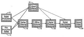
- FIG. 1 depicts a flow chart illustrating the elements of a workflow for producing an audio-visual program in accordance with an illustrative embodiment of the present principles
- FIG. 2 depicts a block schematic diagram of the elements associated with a digital cinematography workflow in accordance with an illustrative embodiment of the new principles
- FIG. 3 depicts a block schematic diagram of the elements associated with a digital cinematography workflow for producing digital dailies from images captured by a digital video camera in accordance with an illustrative embodiment of the new principles
- FIG. 4 depicts a block schematic diagram of the elements associated with a workflow for producing dailies from images captured by a film camera in accordance with an illustrative embodiment of the new principles
- FIG. 5 depicts a block schematic diagram of the elements associated with a workflow for producing digital dailies and for achieving quality control in accordance with an illustrative embodiment of the new principles
- FIG. 6 depicts a block schematic diagram of the elements associated with a workflow for on-set dailies viewing in accordance with an illustrative embodiment of the new principles
- FIG. 7 depicts a block schematic diagram of the elements associated with a workflow for post-preview conformation and timing in accordance with an illustrative embodiment of the new principles
- FIG. 8 depicts a block schematic diagram of the elements associated with a workflow for post visual effects scanning in accordance with an illustrative embodiment of the new principles.
- FIG. 9 depicts a block schematic diagram of the elements associated with a workflow for post-Digital Intermediate generation and finishing in accordance with an illustrative embodiment of the new principles.
- FIG. 1 depicts the elements in a workflow 10 associated with the production of an audio-visual work in accordance with a preferred embodiment of the present principles.
- the audio-visual program takes the form of a pre-recorded digital versatile disc (DVD), some times referred to as a digital video disk, containing at least one feature presentation such as a movie or television show.
- DVD digital versatile disc
- the audio-visual program could take the form of a movie in either digital or analog form for theatrical presentation.
- the workflow 10 commences with content creation (e.g., image capture) by making use of one or more digital image capture devices (e.g., Thomson Grass Valley Viper film stream cameras) during digital production in step 12 .
- Image capture also can occur during by making use of one or more film cameras during film production in step 14 . (Indeed both digital production and film production could occur in some circumstances)
- the capture of audio information can occur simultaneously during either of steps 12 or 14 .
- audio capture and/or processing can occur during subsequent processing operations.
- preliminary adjustments to the captured images can occur such as, but not limited to, color adjustment, by passing the digital video output signal/file(s) of the digital image capture device(s) through a color corrector (not shown) in a manner describer in greater detail hereinafter.
- color adjustment the transfer of the digital output signal/file(s) through the color corrector will yield a color decision list (CDL), taking the form of metadata reflective of the color adjustments that were made.
- CDL color decision list
- the film typically undergoes transfer to a telecine device (not shown), such as the Thomson Grass Valley Spirit film scanner which has been calibrated to a reference film, allowing repeatability in successive scans, to yield a digital output signal/file(s) as described in greater detail hereinafter.
- a telecine device such as the Thomson Grass Valley Spirit film scanner which has been calibrated to a reference film, allowing repeatability in successive scans, to yield a digital output signal/file(s) as described in greater detail hereinafter.
- the digital output signal/file(s) generated during digital production in step 12 can undergo color correction
- the digital output signal/file(s) generated by the telecine device during step 14 can also undergo transfer through a color corrector, thereby giving rise to a CDL indicative of the color adjustments that were made.
- the individuals responsible for content creation such as the Director and/or the Director of Photography, often want to view all or a portion of the captured images, usually on a daily basis, during step 16 .
- the portions of the captured images that undergo daily viewing bear the designation “dailies” or “rushes”.
- the viewing of dailies during step 16 can occur by simply transferring the digital output file(s) following image (e.g., color) correction, if any to a digital display device, e.g., a television monitor or digital projector.
- the viewing of dailies during step 16 occurs by sending the digital output signal/file(s) from the film scanner following image (e.g., color) correction if any, to the display device.
- step 16 the Director and/or Director of Photography might wish to make further make image adjustments, such as color correction, in addition to those previously made during steps 12 and 14 .
- color color adjustments can be made by the use of a color corrector (not shown).
- a color corrector not shown.
- the lack of transference of the CDLs to successive image processing operations stemmed from the lack of a common frame of reference.
- the digital video output signal/file(s)s generated at the completion of steps 12 and 14 when displayed on one type digital output device will not necessarily have the same appearance (i.e., “look”) as the color-corrected dailies viewed during step 16 even if the initial CDLs undergoes an adjustment to correspond to the CDL associated with dailies viewing during step 16 .
- the technique of the present principles overcomes this disadvantage by providing a common frame of reference for the CDLs created during successive processing operations.
- the digital output signal/file(s)s generated during each of steps 12 and 14 undergoes a transformation via a Look-Up table (LUT) described hereinafter, to yield digital output signal/file(s) whose images emulate a “normal” film print.
- LUT Look-Up table
- the CDL created during each of steps 12 and 14 becomes correlated to the emulated film print.
- the color-corrected digital output signal/file(s) also undergo transformation to emulate a film print.
- the device(s) utilized for display e.g., the digital television set or digital projector
- the digital video output file whose images emulate a film print will possess the same appearance regardless of the display device. Therefore, the CDL associated with the dailies viewing during step 16 could be obtained by a prescribed modification to initial CDL obtained during steps 12 or 14 . In other words, the CDL obtained during steps 12 or 14 can serve as the starting point for subsequent adjustments.
- the digital video output signal/file(s) also undergo a transformation to emulate film print.
- the digital output signal/file(s)s generated following such transformation serves as the input signal/file(s) to the offline editorial operation performed during step 18 .
- the received input signal/file(s) typically undergo subsequent processing including, but not limited to, image editing, the addition of audio, and/or compression.
- the digital video output signal/file(s) at the end of step 18 undergo a transformation to emulate a film print prior to receipt at step 20 during which preview screenings occur.
- the preview screening operation of step 20 also receives as an input the visual effects created during step 22 .
- digital video output signal/file(s) generated during steps 12 and 14 undergo transfer to a special effects facility, along with the initial CDLs and a three-dimensional Look Up-Table.
- This LUT enables the transformation of the digital output signal/file(s) completed in the course of special effects creation in step 22 to emulate a film print.
- the special effects produced at the completion of step 22 and the digital output signal/file(s) produced following the offline editorial processing during step. 18 undergo conformation. Such conformation corresponds to the traditional process of segmentation and rearrangement of original camera negatives (OCNs) to yield a motion picture film.
- one or more colorists will make final color adjustments using the CDLs generated during the previous processing operations steps as the starting points for final color grading.
- the use of LUTs to transform the digital output signal/file(s) at each processing operation to emulate a film print makes this possible.
- a master CDL gets saved, and new files with corrections burned in undergo rendering and transformation via a LUT to yield an output file whose images emulate a film print for screening at the completion of step 20 .
- the transformed digital output signal/file(s) generated during step 20 serve as the input to the process of creating digital intermediates (e.g. digital audio-visual programs) during step 24 .
- digital intermediates e.g. digital audio-visual programs
- step 24 the received digital signal/file(s) undergo further conformation and a master CDL created during step 20 gets loaded into a Digital Intermediate color correction system (not shown) which can take the same form as the color correction system used for conformation during step 20 .
- a Digital Intermediate color correction system (not shown) which can take the same form as the color correction system used for conformation during step 20 .
- the original negative typically will undergo calibrated scanning at a higher resolution, 2K or 4K.
- This higher resolution digital video output file gets conformed and loaded into the Digital Intermediate color correction system for final color grading and subsequent rendering during which a final color grade gets applied.
- the master CDL created during such color grading gets saved.
- the digital video output signal/file(s) produced during step 24 undergoes transformation via an LUT to emulate a film print that can then undergo distribution to one or more digital cinemas by various means, such as via Internet, Satellite, or physical delivery on a storage medium such as a disk.
- the digital video output file generated at the completion of step 24 also serves as the final Digital Intermediate (digital master) for creating home video digital versatile (DVD) disks during step 26 . Further color grading can occur during step 26 for consumer-type displays. As before, the digital output generated after final grading undergoes a transformation to emulate a film print. Dow conversion to HD or SD occurs as well with the final color grade burned in.
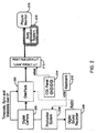
- FIG. 2 depicts a block schematic diagram showing elements of a workflow for digital production during step 12 of FIG. 1 .
- the digital image capture device 200 serves to capture images in digital form (e.g., a stream of digital video).
- the digital image capture device comprises one or more digital television camera, such as the “Viper” Film Stream digital camera from Thomson Grass Valley.
- a storage device 202 stores the digital video output signal/file(s) generated by the image capture device 200 , along with time code knowledge, synchronizing signal/file(s)s and metadata.
- the storage device 202 typically comprises one or more magnetic disk drives arranged in an array.
- the storage device 202 can comprise the “Venom” disk storage pack from Thomson Grass Valley.
- the time code knowledge, synchronizing signal/file(s)s and metadata pass to the storage device 202 out of band from the digital video signal/file(s) generated by the digital image capture device 200 .
- a production system 206 receives the time code knowledge, synchronizing signal/file(s)s and metadata from the digital image capture device 200 for embedding in the audio recorded by a digital sound recorder 208 .
- the production system 206 also collects
- the digital sound recorder 208 records audio associated the visual information captured by the digital image capture device 200 . Audio from the digital sound recorder 208 undergoes storage in the storage device 202 , along with the digital output signal/file(s) representing captured images, along with, the time code knowledge, synchronizing signal/file(s)s and metadata.
- the production system 206 can also embed external information entered by an operator through a keyboard 210 such as Color Decision List (CDL) and/or Avid Log Exchange (ALE) data.
- a keyboard 210 such as Color Decision List (CDL) and/or Avid Log Exchange (ALE) data.
- CDL Color Decision List
- ALE Avid Log Exchange
- USB Universal Serial Bus
- Other well known protocols could serve to facilitate coupling the keyboard 210 to the production system 206 .
- a processing system 212 processes digital output signal/file(s) from the storage device 202 using the accompanying time code knowledge, synchronizing signal/file(s)s and metadata. Additionally, the processing system 212 can make use of CDL data received from a CDL entry device 214 to enable color adjustments.
- a colorist will make adjustments through the CDL entry device 214 to the color of the captured images. Such adjustments allow the Director and/or Director of Photography to see how corresponding color adjustments might impact the final version the audio-visual program produced from the captured video. Adjustments to other image parameters can be made in a similar manner, using an input device (not shown), similar to the CDL entry device 214 .
- the processing system 212 typically comprises one or more programmed computers that include or have access to one or more Look-Up Tables (LUTs) that can transform the capture image information embodied in the digital output signal/file(s) originated by the digital image capture device(s) to emulate a film print as discussed previously.
- LUTs can undergo dynamic change, especially in response to the color adjustments entered via the CDL entry device 214 .
- the processing system 212 can transform captured images embodied in the digital output signal/file(s) to emulate a film print as well as to change the overall appearance of captures images, such as by modifying their color and/or other image characteristics.
- the digital video output signal/file(s) transformed by the processing system 212 typically undergo display on a display device 216 , such as a video monitor.
- a display device 216 such as a video monitor.
- an automatic calibration system 218 will periodically calibrate the display device 216 with regard to various settings, such as color, linearity, focus and contrast for example.
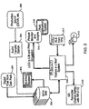
- FIG. 3 a block schematic diagram showing the elements of a workflow for production of instant dailies in connection with dailies viewing during step 16 of FIG. 1 .
- at least one storage facility 300 typically in the form of a Storage Area Network (SAN) receives digital video output signal/file(s) 301 from the system 212 of FIG. 2 following their transformation to emulate a film print.
- the SAN 300 makes use of Serial Advanced Technology Attachment (SATA) for connecting to other devices.
- SATA Serial Advanced Technology Attachment
- An archive system 302 connected to the SAN 300 can create one or more deliverables comprising all or a portion of the digital output signal/file(s) stored in the SAN.
- deliverables take the form of tapes or other transportable storage mediums, such as transportable hard disk drives, that store information for export to an external entity, such as a visual special effects (VFX) facility.
- VFX visual special effects
- the SAN 300 of FIG. 3 can also receive digital audio from an audio transfer station 304 supplied with audio from one or more sources 306 , only one of which is shown.
- the audio source(s) 306 could include digital sound recorders or other devices that provide audio in digital form.
- the audio transfer station 304 enables editing of the digital audio prior to storage in the SAN 300 .
- the audio transfer station 304 can include any of several different types of systems for performing post-production operations, including but not limited to audio correction and/or adjustment.
- the audio transfer station 304 comprises part of the Thomson Grass Valley “Bones” post production framework, which includes one or more processors programmed with software that allows editing, correction and/or manipulation of digital audio.
- the digital output signal/file(s) stored in the SAN 300 undergo processing via a processing system 308 .
- the processing system 308 of FIG. 3 includes one or more LUTs for transforming digital output signal/file(s) so that the images embodied in those. files emulate the look of a motion picture film print.
- the LUT(s) also enable changing the appearance of one or more images characteristics, such as color, the latter occurring in accordance with Color Decision List (CDL) and/or Automatic Link Enablement (ALE) information 317 exported from the production system 206 of FIG. 2 .
- the processing system 308 comprises the Thomson Grass Valley “Bones” post production framework.
- a single post production framework, such as the “Bones” post production framework could perform the functions of the processing system 308 and the audio transfer station 304 of FIG. 3 .
- the processing system 308 generates digital output signal/file(s) that embody one or more audio-visual program(s) in digital form, along with associated time code knowledge, synchronizing information and metadata for distribution to several destinations.
- the audio-visual program(s) embodied in the digital output signal/file(s) generated by the processing system 308 typically have undergone a transformation to emulate a film-print.
- the processing system 308 can also provide the digital output signal/file(s) embodying the audio-visual program(s) to a recorder 310 .
- the processing system 308 can output the digital output more files in any one of a variety of formats 312 , such as JPEG 2000, Avid® Media, Apple® FCP, DVD images and the like.
- processing system 308 can make use of one or more internal look-up tables to convert LOG-based video embodied in the digital output signal/file(s) to linear-based video and to apply film print emulation to yield video for display on a display system 314 , such as a video monitor or a scope.
- An auto calibration system 316 similar to auto calibration system 218 , serves to calibrate the display system 314 .
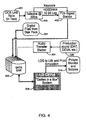
- FIG. 4 depicts a block schematic diagram showing the elements of a workflow for producing digital dailies from filmed images created during film production in step 14 of FIG. 1 .
- the workflow of FIG. 4 contains many elements in common with the workflow of FIG. 3 and therefore, like reference numbers reference like elements in FIG. 3 .
- the workflow of FIG. 4 makes use telecine 400 , such as the Thomson Grass Valley Spirit film scanner, for scanning Original Camera Negative (OCN) rolls 401 .
- OCN Original Camera Negative
- the Thomson Grass Valley “Spirit” film scanner offers both 2K and 4K resolution, and thus can generate two separate files for a scanned film, one having 4K resolution and the other with 2K resolution.
- the scanner 400 operates at 30 frames per second (fps), which is typically faster than the 24 fps, the speed at which images are typically captured onto the OCN rolls 401 , thereby allowing the scanner to operate at greater than real time speed, as measured with respect to the film exposure rate.
- fps frames per second
- the scanner 400 has a ten-bit High Definition Serial Data Interface (HD SDI) for generating digital output signal/file(s) in a 4:4:4 format for receipt at a receiving (e.g., ingest) station 402 , typically part of the Thomson Grass Valley “Bones” post processing framework.
- a receiving station 402 typically part of the Thomson Grass Valley “Bones” post processing framework.
- the ingest station 402 also receives a key code from the scanner 400 identifying the particular OCN roll 401 undergoing scanning.
- the receiving station 402 collects the digital output signal/file(s) from the scanner 400 for transfer to the SAN 300 to allow further processing by the processing system 308 as described previously with respect to FIG. 3 .
- the processing unit 308 In addition to receiving digital output signal/file(s) originated by the scanner 400 and stored by the SAN 300 , the processing unit 308 also receives audio files stored by the SAN 300 following their receipt from the audio transfer station 304 which processed such files received from one of the audio sources 306 . Also, as described previously, the archive system 302 connected to the SAN 300 can create one or more deliverables comprising all or a portion of the digital output signal/file(s) stored in the SAN.
- the processing system 308 generates more or more digital output signal/file(s) embodying one or more audio-visual programs for display on a picture monitor or scope 314 .
- the processing system 308 can make use of one or more internal look-up tables to convert LOG-based video embodied in the digital output signal/file(s) to linear-based video and to apply film print emulation in connection with the digital output signal/file(s) supplied to the display device 314 .
- FIG. 5 depicts a block schematic diagram showing the elements of a workflow for dailies distribution in connection with the dailies viewing operation in step 16 of FIG. 1 .
- the dailies distribution workflow of FIG. 5 utilizes many of the same elements as the workflows depicted in FIGS. 3 and 4 and like reference numbers reference like elements.
- the SAN 300 supplies the processing system 308 with digital output signal/file(s) processing, (the files including both video and audio, typically combined in one or more audio-visual programs). In the course of such processing by the processing system 308 , an operator can undertake quality control and verification as required. Also, as described previously, the SAN 300 provides digital output signal/file(s) to the archive system. 302 which can create one or more deliverables comprising all or a portion of the digital output signal/file(s) stored in the SAN.
- the digital output signal/file(s) produced by the processing system 308 embody one or more audio-visual-programs in one or more formats 312 .
- Such files constitute digital dailies for display on the display device 314 .
- the processing system 308 can make use of one or more internal look-up tables to convert LOG-based video embodied in the digital output signal/file(s) to linear-based video and to apply film print emulation in connection with the digital output signal/file(s) supplied to the display device 314 .
- the audio-visual program(s) embodied in the files output by the processing system 308 typically undergo transmission via a network 500 .
- the transmission network 500 can comprise one or more public and/or private networks, which can include wired and/or wireless networks of various types. Selection of the network(s) will depend on bandwidth and time availability.
- the digital output signal/file(s) Prior to transmission on the network 500 , can undergo watermarking, typically via a watermarking station (not shown) that performs “Nextamp Watermarking” using software such as the “Portable Media Package (PMP).
- PMP Portable Media Package
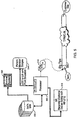
- FIG. 6 depicts a block schematic diagram showing elements of a workflow for on-set dailies viewing during step 16 of FIG. 1 .
- a server 600 receives one or more of the digital output signal/file(s) containing one or more audio-visual programs embodying the digital dailies for viewing, such as those produced by the processing system, 308 of FIGS. 3-5 .
- the digital output signal/file(s) received by the server 600 take the form of raw uncorrected source files encoded in the JPEG 2000 format.
- the serve 600 In order to commence play out, the serve 600 must receive a security code, typically entered via a Universal Serial Bus (USB) flash memory device 602 . Other data entry devices, such as a keyboard (not shown) could facilitate entry of the security code.
- USB Universal Serial Bus
- the server 600 Upon receipt of the proper security code via the flash memory 602 , the server 600 will supply one or more digital output signal/file(s) whose video exists in a LOG format for display on a display device 604 to effect the display of digital dailies. To emulate a film print for display on the display device 604 , the server 600 can perform a LOG to LIN conversion of the video embodied in the digital output signal/file(s) via a LUT, prior to receipt of the signal/file(s) by the display device. To assure color consistency, a calibration system 606 can serve to calibrate the display device 604 .
- the server 600 can makes use of CDL data 607 supplied from a server (not shown) at a post facility during real time viewing of digital dailies on the display device 604 . During such viewing, the Director and/or Director of Photography can make changes to the CDL. To that end, a CDL entry device 608 connects to the server 600 to enable adjustments to the CDL. Other image adjustments can be made in a similar manner through the use of corresponding image adjustment entry devices (not shown). Following changes made to the CDL via the CDL entry 608 , the server 600 will transmit those changes to the CDL server 607 at the post facility.
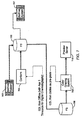
- FIG. 7 depicts a block schematic diagram showing the elements of a workflow for post-preview conformation and timing in connection with step 20 of FIG. 1 .
- the conformation performed during the workflow of FIG. 7 corresponds to the traditional segmentation and rearrangement of original camera negatives (OCNs) to yield a motion picture film.
- the timing performed during the workflow of FIG. 7 corresponds to the traditional process of adjusting (e.g., grading) the color balance of each scene.
- a first server 702 receives one or more digital output signal/file(s) from the archive system 302 , typically in a raw 4:4:4 log form.
- the server 702 comprises part of the Stone FS high speed fibre channel solution available from Autodesk Inc, San Raphael, Calif.
- a conformation system 704 performs editing and finishing of the files supplied from the file server 702 in accordance with Edit Decision List (EDL) data, and time code information from one or more external sources.
- the conformation system 704 typically takes the form of one or more processors running image finishing software such as Autodesk FIRE® and/or Autodesk SMOKE® software. Such software (or its equivalent) enables the conformation system 704 to accomplish preview conformance (e.g., editing and assembling).
- the conformation system returns 704 the signal/file(s) to the file server 702 for transfer to a second file server 706 and an archive system. 707 .
- the server 704 comprises part of the Stone FS high speed fibre channel solution available from Autodesk Inc, San Raphael, Calif.
- a color grading system 708 performs color grading on the digital output signal/file(s) (i.e., audio-visual works) stored in the filer server 706 using CDL data associated with the digital dailies as a pre-grade.
- the color grading system 708 comprises one or more processors running color grading software such as Autodesk LUSTRE® software.
- the digital output signal/file(s) produced by the color grading system 708 undergo storage on a preview server 710 .
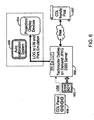
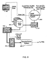
- FIG. 8 depicts a block schematic diagram showing the elements of a workflow for post-visual effects scanning in connection with visual effects production during step 22 of FIG. 1 .
- the post-visual effects workflow makes use many of the elements described previously with respect to FIG. 4 and like reference numbers describe like elements.
- the scanner 400 scans OCNs to yield both 2K and 4K resolution digital output signal/file(s) for storage in the SAN 300 .
- the scanner 400 also supplies a scan list identifying the film scanned to an asset management system 800 , typically comprising a database that resides on a server (not shown) for tracking various activities (typically referred to projects) in the course of post-visual effects scanning.
- Each project corresponds to a particular film scan, and to that end, the management system 800 will provide a link between such film scans and associated file names and key code relationships, as well as proxy information including links to other servers which can store information associated with that project. Additionally, for each project, the asset management system 800 can also store information regarding the identity of the entity responsible for providing visual special effects (VFX). Further, the asset management system 800 also has the capability of acquiring Edit Decision List(s) and/or ALE data from one or more external sources (not shown.)
- the digital output signal/file(s) stored in the SAN 300 can undergo color grading via a color grading system 708 described with respect to FIG. 7 .
- the color-graded digital output signal/file(s) then undergo transformation via a LUT 802 to emulate a film print.
- the LUT 802 typically will convert the video associated with the digital output signal/file(s) from LOG to LIN and apply print emulation for HD reference if needed.
- a remote preview system 804 serves to convert the digital output signal/file(s) transformed by the LUT 802 , which typically exist in a JPEG 200 format, to an IP format for network streaming, such as over the Internet.
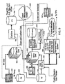
- FIG. 9 depicts a block schematic diagram showing the elements of a workflow for post-Digital Intermediate creation and finishing to yield finished one or more audio-visual program(s) for home distribution and the like in connection with step 26 of FIG. 1 .
- the workflow of FIG. 9 shares many elements in common with the workflows of FIGS. 2-8 and like reference numbers describe like elements.
- the workflow of FIG. 9 makes use of a film scanner, such as scanner 400 , to scan OCNs to yield both 2K and 4K resolution digital output signal/file(s).
- the 2K files from the scanner typically undergo storage in a file server 900 , which like the file servers 702 and 706 of FIG. 7 comprises part of the Stone FS high speed fibre channel solution available from Autodesk Inc, San Raphael, Calif.
- the 4K resolution output signal/file(s) from the scanner 400 undergo storage in a Fiber Channel Storage Area Network (SAN) 902 for subsequent transfer to the SAN 300 which has links to the file servers 702 and 706 as discussed previously with respect to FIG. 7
- the scanner 400 generates a scan list which is received by an Asset Management System, such as Asset Management system 800 described previously with respect to FIG. 8 .
- the scan list can include conformation data for receipt by the Asset management system and by a conformation station, such as conformation system 704 of FIG. 7 .
- the conformation system 704 makes use of the conformation data to perform conformation (e.g., editing and finishing) of digital output signal/file(s) transferred from the SAN 300 to the file server 702 .
- the digital output signal/file(s) produced by the conformation system 704 which embody one or more audio-visual programs, undergo storage in the file 702 for subsequent transfer back to the SAN 300 .
- the now-conformed digital Output signal/file(s) undergo transfer from the SAN 300 to a file server, such as file server 706 , for subsequent transfer to a color grading system, such as color grading system 708 described previously with respect to FIG. 7 for final color grading.
- a color grading system such as color grading system 708 described previously with respect to FIG. 7 for final color grading.
- the digital output signal/file(s) which now embody finished Digital Intermediate(s) (audio-visual program(s)) typically undergo conversion via a LUT 902 to transform the video embodied in the files into a HD 10-bit LOG DPX format suitable for using in mastering DVDs for consumer use.
- the transformed digital output signal/file(s) can include metadata 903 for dissolves.
- the now-conformed files also undergo a transfer to a remote pre-visualization server 904 to enable streaming to remote sites.
- the SAN 300 of FIG. 9 has a link to a quality control station 905 which typically comprises part of the Thomson Grass Valley “Bones” post production framework.
- a quality control station 905 typically comprises part of the Thomson Grass Valley “Bones” post production framework.
- an operator can access stored digital output signal/file(s) embodying one or more audio-visual programs, from the SAN 300 for inspection and modification to improve the quality of at least one of the digital audio and video embedded within such files. To save time, the operator could begin a quality control review prior to completion of color grading.
- the SAN 300 can deliver a digital output files, embodying one or more finished audio-visual program in digital form, for distribution to a Digital Cinema Distribution Master (DCDM) facility 906 .
- DCDM Digital Cinema Distribution Master
- the DCDM 906 facility serves to distribute the digital output signal/file(s) embodying such audio-visual programs in digital form to one or more digital cinemas such as digital cinema 908 .
- the digital output signal/file(s) from the SAN 300 can also undergo transfer to a film printer 920 , such as manufacture by Arri Camera, which can print a corresponding celluloid film negative.
- the SAN 300 enjoys a link to an archive system 707 similar to the archive system 202 , for creating one or more deliverables for export to an external entity.
Abstract
Description
- This application claims priority under 35 119(e) to U.S. Provisional Patent Application Ser. No. 60/773,807, filed Feb. 15, 2006, the teachings of which are incorporated herein.
- This invention relates to a technique for maintaining the consistency of at least one image parameter, such as color, during different phases of producing an audio-visual program, such as a movies or television show.
- Providers of audio-visual programs, such as movies, and television shows generally follow a well known workflow to create, process, and distribute such audio-visual programs to viewers. The process of creating content generally entails the capture of visual images and audio (although in some instances, the audio gets added and/or modified after image capture). Traditionally, motion picture film cameras have been used to capture visual images. While film cameras often remain the device of choice, digital video cameras, such as the Thomson Grass Valley Viper film stream camera have increased in popularity. The use of digital video cameras afford the advantage of eliminating the need to digitize the images captured by the film camera(s) for subsequent digital processing, e.g., adding visual effects.
- In the course of content creation, the director and/or director of photography typically want to review all or at least a portion of the captured images, usually on a daily basis. The terms “digital dailies” or “rushes” generally refer to the captured images viewed on such a daily basis. In the case of film, the captured images usually undergo a transfer to a telecine device such as the Thomson Grass Valley Spirit telecine device. The telecine device scans the film to create a digital output file(s) or a digital video signal for recording and for display on a television set or digital projector. In some instances, such digital output file(s) first undergo processing prior to display. In the course of scanning the film, a colorist can apply color correction, giving rise to a color decision list (CDL) that typically exists as metadata associated with the digital output file(s) of the telecine. Such metadata will indicate the color correction decisions made by the colorist. By its very nature, a digital video camera, such as the Thomson Grass Valley Viper digital video camera, produces digital output file(s) representative of the captured images. Thus, no need exists for any transfer to a telecine device. Like the digital output file(s) from the telecine, the digital output file(s) from the digital video camera(s) usually undergo color correction in the course of creating digital dailies (i.e., digital files representative of captured images).
- In the past, the CDL generated in the course of creating digital dailies has played little if any role in later processing operations such as Digital Intermediate generation. Presently, each successive processing operation in the workflow associated with the creation, processing and production of an audio-visual program produces different CDLs that bear little if any relationship with the CDL created during any of the preceding processing operations. One reason for the lack of a relationship between the CDLs associated with successive processing operations has been the inability to provide a consistent frame of reference (base exposure and color and final intended display device emulation) for such CDL for each processing operation.
- Thus a need exists for an image processing technique that enables image processing information, such as, but not limited to, the CDL associated with a given processing operation to be carried forward to a subsequent processing operation.
- Briefly, in accordance with an illustrative embodiment of the present principles, there is provided a method for processing image information that enables at least one image decision list associated with a given image processing operation to be carried through to at least one subsequent processing operation. The method of the present principles commences by generating initial image decision list indicative of a change in at least one image characteristic adjusted during a first image processing operation. For example, the initial image decision list could comprise a Color Decision List (CDL) indicative of a color adjustment made during an image processing operation. This operation can include displaying the image while emulating the final intended display medium. During a second image processing operation, the initial image decision list undergoes modification to further adjust the at least one image characteristic in accordance with the emulating the final intended display medium used in the first step. In the case of film, a rescan of the film must yield the identical relationship of density (and color) to code value of the original scan by using a standardized calibration procedure.
- The method of the present principles advantageously enables an image decision list, such as a CDL, made during a particular image processing operation to be carried forward during a subsequent processing operation. The transformation of the image following the initial processing operation while emulating the final intended display medium, and same emulation (and standardized calibration procedure if a rescan is required) as the basis for making subsequent image adjustments affords a mechanism for normalizing the image decision list made during each processing operation. In this way, the images decision list will track image adjustments during subsequent image processing operations.
-
FIG. 1 depicts a flow chart illustrating the elements of a workflow for producing an audio-visual program in accordance with an illustrative embodiment of the present principles; -
FIG. 2 depicts a block schematic diagram of the elements associated with a digital cinematography workflow in accordance with an illustrative embodiment of the new principles; -
FIG. 3 depicts a block schematic diagram of the elements associated with a digital cinematography workflow for producing digital dailies from images captured by a digital video camera in accordance with an illustrative embodiment of the new principles; -
FIG. 4 depicts a block schematic diagram of the elements associated with a workflow for producing dailies from images captured by a film camera in accordance with an illustrative embodiment of the new principles; -
FIG. 5 depicts a block schematic diagram of the elements associated with a workflow for producing digital dailies and for achieving quality control in accordance with an illustrative embodiment of the new principles; -
FIG. 6 depicts a block schematic diagram of the elements associated with a workflow for on-set dailies viewing in accordance with an illustrative embodiment of the new principles; -
FIG. 7 depicts a block schematic diagram of the elements associated with a workflow for post-preview conformation and timing in accordance with an illustrative embodiment of the new principles; -
FIG. 8 depicts a block schematic diagram of the elements associated with a workflow for post visual effects scanning in accordance with an illustrative embodiment of the new principles; and -
FIG. 9 depicts a block schematic diagram of the elements associated with a workflow for post-Digital Intermediate generation and finishing in accordance with an illustrative embodiment of the new principles. -
FIG. 1 depicts the elements in aworkflow 10 associated with the production of an audio-visual work in accordance with a preferred embodiment of the present principles. Illustratively inFIG. 1 , the audio-visual program takes the form of a pre-recorded digital versatile disc (DVD), some times referred to as a digital video disk, containing at least one feature presentation such as a movie or television show. Alternatively, or in addition to the pre-recorded DVD, the audio-visual program could take the form of a movie in either digital or analog form for theatrical presentation. - The
workflow 10 commences with content creation (e.g., image capture) by making use of one or more digital image capture devices (e.g., Thomson Grass Valley Viper film stream cameras) during digital production instep 12. Image capture also can occur during by making use of one or more film cameras during film production instep 14. (Indeed both digital production and film production could occur in some circumstances) The capture of audio information can occur simultaneously during either ofsteps - During digital production in
step 12, preliminary adjustments to the captured images, can occur such as, but not limited to, color adjustment, by passing the digital video output signal/file(s) of the digital image capture device(s) through a color corrector (not shown) in a manner describer in greater detail hereinafter. In the case of color adjustment, the transfer of the digital output signal/file(s) through the color corrector will yield a color decision list (CDL), taking the form of metadata reflective of the color adjustments that were made. - In the case of film production during
step 14, the film typically undergoes transfer to a telecine device (not shown), such as the Thomson Grass Valley Spirit film scanner which has been calibrated to a reference film, allowing repeatability in successive scans, to yield a digital output signal/file(s) as described in greater detail hereinafter. Just as the digital output signal/file(s) generated during digital production instep 12 can undergo color correction, the digital output signal/file(s) generated by the telecine device duringstep 14 can also undergo transfer through a color corrector, thereby giving rise to a CDL indicative of the color adjustments that were made. - Following
steps step 16. The portions of the captured images that undergo daily viewing bear the designation “dailies” or “rushes”. In the case of images captured by the digital image capture devices during digital production instep 12, the viewing of dailies duringstep 16 can occur by simply transferring the digital output file(s) following image (e.g., color) correction, if any to a digital display device, e.g., a television monitor or digital projector. In the case of film production, the viewing of dailies duringstep 16 occurs by sending the digital output signal/file(s) from the film scanner following image (e.g., color) correction if any, to the display device. - During dailies viewing in
step 16, the Director and/or Director of Photography might wish to make further make image adjustments, such as color correction, in addition to those previously made duringsteps steps step 16, and for that matter, any of the succeeding processing operations. The lack of transference of the CDLs to successive image processing operations stemmed from the lack of a common frame of reference. For example, the digital video output signal/file(s)s generated at the completion ofsteps step 16 even if the initial CDLs undergoes an adjustment to correspond to the CDL associated with dailies viewing duringstep 16. - As described in greater detail below, the technique of the present principles overcomes this disadvantage by providing a common frame of reference for the CDLs created during successive processing operations. The digital output signal/file(s)s generated during each of
steps steps - During
step 16, the color-corrected digital output signal/file(s) also undergo transformation to emulate a film print. Further, the device(s) utilized for display (e.g., the digital television set or digital projector) comprise calibrated devices. Thus, the digital video output file whose images emulate a film print will possess the same appearance regardless of the display device. Therefore, the CDL associated with the dailies viewing duringstep 16 could be obtained by a prescribed modification to initial CDL obtained duringsteps steps - During
step 16, the digital video output signal/file(s) also undergo a transformation to emulate film print. The digital output signal/file(s)s generated following such transformation serves as the input signal/file(s) to the offline editorial operation performed duringstep 18. Duringstep 18, the received input signal/file(s) typically undergo subsequent processing including, but not limited to, image editing, the addition of audio, and/or compression. As with the previous image processing operations, the digital video output signal/file(s) at the end ofstep 18 undergo a transformation to emulate a film print prior to receipt atstep 20 during which preview screenings occur. - The preview screening operation of
step 20 also receives as an input the visual effects created duringstep 22. In practice, digital video output signal/file(s) generated duringsteps step 22 to emulate a film print. Duringstep 20, the special effects produced at the completion ofstep 22 and the digital output signal/file(s) produced following the offline editorial processing during step.18 undergo conformation. Such conformation corresponds to the traditional process of segmentation and rearrangement of original camera negatives (OCNs) to yield a motion picture film. During preview screening instep 20, one or more colorists will make final color adjustments using the CDLs generated during the previous processing operations steps as the starting points for final color grading. The use of LUTs to transform the digital output signal/file(s) at each processing operation to emulate a film print makes this possible. Following final color grading, a master CDL gets saved, and new files with corrections burned in undergo rendering and transformation via a LUT to yield an output file whose images emulate a film print for screening at the completion ofstep 20. - Along with the special effects generated during
step 22, the transformed digital output signal/file(s) generated duringstep 20 serve as the input to the process of creating digital intermediates (e.g. digital audio-visual programs) duringstep 24. Duringstep 24, the received digital signal/file(s) undergo further conformation and a master CDL created duringstep 20 gets loaded into a Digital Intermediate color correction system (not shown) which can take the same form as the color correction system used for conformation duringstep 20. To the extent that the captured images were originated during film production instep 14, the original negative typically will undergo calibrated scanning at a higher resolution, 2K or 4K. This higher resolution digital video output file gets conformed and loaded into the Digital Intermediate color correction system for final color grading and subsequent rendering during which a final color grade gets applied. As before, the master CDL created during such color grading gets saved. The digital video output signal/file(s) produced duringstep 24 undergoes transformation via an LUT to emulate a film print that can then undergo distribution to one or more digital cinemas by various means, such as via Internet, Satellite, or physical delivery on a storage medium such as a disk. - The digital video output file generated at the completion of
step 24 also serves as the final Digital Intermediate (digital master) for creating home video digital versatile (DVD) disks duringstep 26. Further color grading can occur duringstep 26 for consumer-type displays. As before, the digital output generated after final grading undergoes a transformation to emulate a film print. Dow conversion to HD or SD occurs as well with the final color grade burned in. -
FIG. 2 depicts a block schematic diagram showing elements of a workflow for digital production duringstep 12 ofFIG. 1 . As shown inFIG. 2 , at least one digitalimage capture device 200 serves to capture images in digital form (e.g., a stream of digital video). In the illustrative embodiment, the digital image capture device comprises one or more digital television camera, such as the “Viper” Film Stream digital camera from Thomson Grass Valley. Astorage device 202 stores the digital video output signal/file(s) generated by theimage capture device 200, along with time code knowledge, synchronizing signal/file(s)s and metadata. Thestorage device 202 typically comprises one or more magnetic disk drives arranged in an array. For example, thestorage device 202 can comprise the “Venom” disk storage pack from Thomson Grass Valley. In practice, the time code knowledge, synchronizing signal/file(s)s and metadata pass to thestorage device 202 out of band from the digital video signal/file(s) generated by the digitalimage capture device 200. - A
production system 206 receives the time code knowledge, synchronizing signal/file(s)s and metadata from the digitalimage capture device 200 for embedding in the audio recorded by adigital sound recorder 208. Theproduction system 206 also collects - Color Decision List (CDL) and/or Automatic Link Enablement data (ALE) generated hereinafter as discussed below for subsequent export for use by other systems (not shown). In practice, the
digital sound recorder 208 records audio associated the visual information captured by the digitalimage capture device 200. Audio from thedigital sound recorder 208 undergoes storage in thestorage device 202, along with the digital output signal/file(s) representing captured images, along with, the time code knowledge, synchronizing signal/file(s)s and metadata. - In addition to embedding the time code knowledge, synchronizing signal/file(s)s and other metadata, the
production system 206 can also embed external information entered by an operator through akeyboard 210 such as Color Decision List (CDL) and/or Avid Log Exchange (ALE) data. Typically, thekeyboard 210 connects to theproduction system 206 through a Universal Serial Bus (USB) connection. Other well known protocols could serve to facilitate coupling thekeyboard 210 to theproduction system 206. - A
processing system 212 processes digital output signal/file(s) from thestorage device 202 using the accompanying time code knowledge, synchronizing signal/file(s)s and metadata. Additionally, theprocessing system 212 can make use of CDL data received from aCDL entry device 214 to enable color adjustments. In practice, an operator, usually referred to as a “colorist” will make adjustments through theCDL entry device 214 to the color of the captured images. Such adjustments allow the Director and/or Director of Photography to see how corresponding color adjustments might impact the final version the audio-visual program produced from the captured video. Adjustments to other image parameters can be made in a similar manner, using an input device (not shown), similar to theCDL entry device 214. - The
processing system 212 typically comprises one or more programmed computers that include or have access to one or more Look-Up Tables (LUTs) that can transform the capture image information embodied in the digital output signal/file(s) originated by the digital image capture device(s) to emulate a film print as discussed previously. The LUTs can undergo dynamic change, especially in response to the color adjustments entered via theCDL entry device 214. In this way, theprocessing system 212 can transform captured images embodied in the digital output signal/file(s) to emulate a film print as well as to change the overall appearance of captures images, such as by modifying their color and/or other image characteristics. - The digital video output signal/file(s) transformed by the
processing system 212 typically undergo display on adisplay device 216, such as a video monitor. To assure optimal picture quality, anautomatic calibration system 218 will periodically calibrate thedisplay device 216 with regard to various settings, such as color, linearity, focus and contrast for example. -
FIG. 3 a block schematic diagram showing the elements of a workflow for production of instant dailies in connection with dailies viewing duringstep 16 ofFIG. 1 . As seen inFIG. 3 , at least onestorage facility 300, typically in the form of a Storage Area Network (SAN) receives digital video output signal/file(s) 301 from thesystem 212 ofFIG. 2 following their transformation to emulate a film print. Preferably, theSAN 300 makes use of Serial Advanced Technology Attachment (SATA) for connecting to other devices. Anarchive system 302 connected to theSAN 300 can create one or more deliverables comprising all or a portion of the digital output signal/file(s) stored in the SAN. In practice, such deliverables take the form of tapes or other transportable storage mediums, such as transportable hard disk drives, that store information for export to an external entity, such as a visual special effects (VFX) facility. - The
SAN 300 ofFIG. 3 can also receive digital audio from anaudio transfer station 304 supplied with audio from one ormore sources 306, only one of which is shown. In practice, the audio source(s) 306 could include digital sound recorders or other devices that provide audio in digital form. Theaudio transfer station 304 enables editing of the digital audio prior to storage in theSAN 300. Theaudio transfer station 304 can include any of several different types of systems for performing post-production operations, including but not limited to audio correction and/or adjustment. In the illustrated embodiment, theaudio transfer station 304 comprises part of the Thomson Grass Valley “Bones” post production framework, which includes one or more processors programmed with software that allows editing, correction and/or manipulation of digital audio. - The digital output signal/file(s) stored in the
SAN 300, which embody one or more audio-visual programs in digital form, undergo processing via aprocessing system 308. Like theprocessing system 212 ofFIG. 1 , theprocessing system 308 ofFIG. 3 includes one or more LUTs for transforming digital output signal/file(s) so that the images embodied in those. files emulate the look of a motion picture film print. The LUT(s) also enable changing the appearance of one or more images characteristics, such as color, the latter occurring in accordance with Color Decision List (CDL) and/or Automatic Link Enablement (ALE)information 317 exported from theproduction system 206 ofFIG. 2 . In practice, theprocessing system 308 comprises the Thomson Grass Valley “Bones” post production framework. A single post production framework, such as the “Bones” post production framework, could perform the functions of theprocessing system 308 and theaudio transfer station 304 ofFIG. 3 . - The
processing system 308 generates digital output signal/file(s) that embody one or more audio-visual program(s) in digital form, along with associated time code knowledge, synchronizing information and metadata for distribution to several destinations. The audio-visual program(s) embodied in the digital output signal/file(s) generated by theprocessing system 308 typically have undergone a transformation to emulate a film-print. Theprocessing system 308 can also provide the digital output signal/file(s) embodying the audio-visual program(s) to arecorder 310. Also, theprocessing system 308 can output the digital output more files in any one of a variety offormats 312, such asJPEG 2000, Avid® Media, Apple® FCP, DVD images and the like. Further, theprocessing system 308 can make use of one or more internal look-up tables to convert LOG-based video embodied in the digital output signal/file(s) to linear-based video and to apply film print emulation to yield video for display on adisplay system 314, such as a video monitor or a scope. Anauto calibration system 316, similar toauto calibration system 218, serves to calibrate thedisplay system 314. -
FIG. 4 depicts a block schematic diagram showing the elements of a workflow for producing digital dailies from filmed images created during film production instep 14 ofFIG. 1 . The workflow ofFIG. 4 contains many elements in common with the workflow ofFIG. 3 and therefore, like reference numbers reference like elements inFIG. 3 . To transform the film images created during film production instep 14 ofFIG. 1 into digital output signal/file(s), the workflow ofFIG. 4 makesuse telecine 400, such as the Thomson Grass Valley Spirit film scanner, for scanning Original Camera Negative (OCN) rolls 401. The Thomson Grass Valley “Spirit” film scanner offers both 2K and 4K resolution, and thus can generate two separate files for a scanned film, one having 4K resolution and the other with 2K resolution. In practice, thescanner 400 operates at 30 frames per second (fps), which is typically faster than the 24 fps, the speed at which images are typically captured onto the OCN rolls 401, thereby allowing the scanner to operate at greater than real time speed, as measured with respect to the film exposure rate. - The
scanner 400 has a ten-bit High Definition Serial Data Interface (HD SDI) for generating digital output signal/file(s) in a 4:4:4 format for receipt at a receiving (e.g., ingest)station 402, typically part of the Thomson Grass Valley “Bones” post processing framework. In practice, the ingeststation 402 also receives a key code from thescanner 400 identifying the particular OCN roll 401 undergoing scanning. The receivingstation 402 collects the digital output signal/file(s) from thescanner 400 for transfer to theSAN 300 to allow further processing by theprocessing system 308 as described previously with respect toFIG. 3 . In addition to receiving digital output signal/file(s) originated by thescanner 400 and stored by theSAN 300, theprocessing unit 308 also receives audio files stored by theSAN 300 following their receipt from theaudio transfer station 304 which processed such files received from one of theaudio sources 306. Also, as described previously, thearchive system 302 connected to theSAN 300 can create one or more deliverables comprising all or a portion of the digital output signal/file(s) stored in the SAN. - The
processing system 308 generates more or more digital output signal/file(s) embodying one or more audio-visual programs for display on a picture monitor orscope 314. As described previously with respect toFIG. 3 , theprocessing system 308 can make use of one or more internal look-up tables to convert LOG-based video embodied in the digital output signal/file(s) to linear-based video and to apply film print emulation in connection with the digital output signal/file(s) supplied to thedisplay device 314. -
FIG. 5 depicts a block schematic diagram showing the elements of a workflow for dailies distribution in connection with the dailies viewing operation instep 16 ofFIG. 1 . The dailies distribution workflow ofFIG. 5 utilizes many of the same elements as the workflows depicted inFIGS. 3 and 4 and like reference numbers reference like elements. As discussed above with respect toFIGS. 3 and 4 , theSAN 300 supplies theprocessing system 308 with digital output signal/file(s) processing, (the files including both video and audio, typically combined in one or more audio-visual programs). In the course of such processing by theprocessing system 308, an operator can undertake quality control and verification as required. Also, as described previously, theSAN 300 provides digital output signal/file(s) to the archive system. 302 which can create one or more deliverables comprising all or a portion of the digital output signal/file(s) stored in the SAN. - The digital output signal/file(s) produced by the
processing system 308 embody one or more audio-visual-programs in one ormore formats 312. Such files constitute digital dailies for display on thedisplay device 314. As discussed previously, theprocessing system 308 can make use of one or more internal look-up tables to convert LOG-based video embodied in the digital output signal/file(s) to linear-based video and to apply film print emulation in connection with the digital output signal/file(s) supplied to thedisplay device 314. - The audio-visual program(s) embodied in the files output by the
processing system 308 typically undergo transmission via anetwork 500. Thetransmission network 500 can comprise one or more public and/or private networks, which can include wired and/or wireless networks of various types. Selection of the network(s) will depend on bandwidth and time availability. Prior to transmission on thenetwork 500, the digital output signal/file(s) can undergo watermarking, typically via a watermarking station (not shown) that performs “Nextamp Watermarking” using software such as the “Portable Media Package (PMP). -
FIG. 6 depicts a block schematic diagram showing elements of a workflow for on-set dailies viewing duringstep 16 ofFIG. 1 . As illustrated inFIG. 6 , aserver 600 receives one or more of the digital output signal/file(s) containing one or more audio-visual programs embodying the digital dailies for viewing, such as those produced by the processing system, 308 ofFIGS. 3-5 . In practice, the digital output signal/file(s) received by theserver 600 take the form of raw uncorrected source files encoded in theJPEG 2000 format. In order to commence play out, the serve 600 must receive a security code, typically entered via a Universal Serial Bus (USB)flash memory device 602. Other data entry devices, such as a keyboard (not shown) could facilitate entry of the security code. - Upon receipt of the proper security code via the
flash memory 602, theserver 600 will supply one or more digital output signal/file(s) whose video exists in a LOG format for display on adisplay device 604 to effect the display of digital dailies. To emulate a film print for display on thedisplay device 604, theserver 600 can perform a LOG to LIN conversion of the video embodied in the digital output signal/file(s) via a LUT, prior to receipt of the signal/file(s) by the display device. To assure color consistency, acalibration system 606 can serve to calibrate thedisplay device 604. - The
server 600 can makes use ofCDL data 607 supplied from a server (not shown) at a post facility during real time viewing of digital dailies on thedisplay device 604. During such viewing, the Director and/or Director of Photography can make changes to the CDL. To that end, aCDL entry device 608 connects to theserver 600 to enable adjustments to the CDL. Other image adjustments can be made in a similar manner through the use of corresponding image adjustment entry devices (not shown). Following changes made to the CDL via theCDL entry 608, theserver 600 will transmit those changes to theCDL server 607 at the post facility. -
FIG. 7 depicts a block schematic diagram showing the elements of a workflow for post-preview conformation and timing in connection withstep 20 ofFIG. 1 . The conformation performed during the workflow ofFIG. 7 corresponds to the traditional segmentation and rearrangement of original camera negatives (OCNs) to yield a motion picture film. The timing performed during the workflow ofFIG. 7 , corresponds to the traditional process of adjusting (e.g., grading) the color balance of each scene. Referring toFIG. 7 , afirst server 702 receives one or more digital output signal/file(s) from thearchive system 302, typically in a raw 4:4:4 log form. In practice, theserver 702 comprises part of the Stone FS high speed fibre channel solution available from Autodesk Inc, San Raphael, Calif. - A
conformation system 704 performs editing and finishing of the files supplied from thefile server 702 in accordance with Edit Decision List (EDL) data, and time code information from one or more external sources. In practice, theconformation system 704 typically takes the form of one or more processors running image finishing software such as Autodesk FIRE® and/or Autodesk SMOKE® software. Such software (or its equivalent) enables theconformation system 704 to accomplish preview conformance (e.g., editing and assembling). Following editing and finishing, the conformation system returns 704 the signal/file(s) to thefile server 702 for transfer to asecond file server 706 and an archive system. 707. Like theserver 702, theserver 704 comprises part of the Stone FS high speed fibre channel solution available from Autodesk Inc, San Raphael, Calif. - A
color grading system 708 performs color grading on the digital output signal/file(s) (i.e., audio-visual works) stored in thefiler server 706 using CDL data associated with the digital dailies as a pre-grade. In practice, thecolor grading system 708 comprises one or more processors running color grading software such as Autodesk LUSTRE® software. The digital output signal/file(s) produced by thecolor grading system 708 undergo storage on apreview server 710. -
FIG. 8 depicts a block schematic diagram showing the elements of a workflow for post-visual effects scanning in connection with visual effects production duringstep 22 ofFIG. 1 . The post-visual effects workflow makes use many of the elements described previously with respect toFIG. 4 and like reference numbers describe like elements. As described, thescanner 400 scans OCNs to yield both 2K and 4K resolution digital output signal/file(s) for storage in theSAN 300. In addition to supplying the 2K and 4K resolution output signal/file(s), thescanner 400 also supplies a scan list identifying the film scanned to anasset management system 800, typically comprising a database that resides on a server (not shown) for tracking various activities (typically referred to projects) in the course of post-visual effects scanning. Each project corresponds to a particular film scan, and to that end, themanagement system 800 will provide a link between such film scans and associated file names and key code relationships, as well as proxy information including links to other servers which can store information associated with that project. Additionally, for each project, theasset management system 800 can also store information regarding the identity of the entity responsible for providing visual special effects (VFX). Further, theasset management system 800 also has the capability of acquiring Edit Decision List(s) and/or ALE data from one or more external sources (not shown.) - The digital output signal/file(s) stored in the
SAN 300 can undergo color grading via acolor grading system 708 described with respect toFIG. 7 . The color-graded digital output signal/file(s) then undergo transformation via aLUT 802 to emulate a film print. To that end, theLUT 802 typically will convert the video associated with the digital output signal/file(s) from LOG to LIN and apply print emulation for HD reference if needed. Aremote preview system 804 serves to convert the digital output signal/file(s) transformed by theLUT 802, which typically exist in aJPEG 200 format, to an IP format for network streaming, such as over the Internet. -
FIG. 9 depicts a block schematic diagram showing the elements of a workflow for post-Digital Intermediate creation and finishing to yield finished one or more audio-visual program(s) for home distribution and the like in connection withstep 26 ofFIG. 1 . The workflow ofFIG. 9 shares many elements in common with the workflows ofFIGS. 2-8 and like reference numbers describe like elements. The workflow ofFIG. 9 makes use of a film scanner, such asscanner 400, to scan OCNs to yield both 2K and 4K resolution digital output signal/file(s). The 2K files from the scanner typically undergo storage in afile server 900, which like thefile servers FIG. 7 comprises part of the Stone FS high speed fibre channel solution available from Autodesk Inc, San Raphael, Calif. The 4K resolution output signal/file(s) from thescanner 400 undergo storage in a Fiber Channel Storage Area Network (SAN) 902 for subsequent transfer to theSAN 300 which has links to thefile servers FIG. 7 . - As discussed previously, the
scanner 400 generates a scan list which is received by an Asset Management System, such asAsset Management system 800 described previously with respect toFIG. 8 . The scan list can include conformation data for receipt by the Asset management system and by a conformation station, such asconformation system 704 ofFIG. 7 . Theconformation system 704 makes use of the conformation data to perform conformation (e.g., editing and finishing) of digital output signal/file(s) transferred from theSAN 300 to thefile server 702. The digital output signal/file(s) produced by theconformation system 704, which embody one or more audio-visual programs, undergo storage in thefile 702 for subsequent transfer back to theSAN 300. - The now-conformed digital Output signal/file(s) undergo transfer from the
SAN 300 to a file server, such asfile server 706, for subsequent transfer to a color grading system, such ascolor grading system 708 described previously with respect toFIG. 7 for final color grading. After final color grading, the digital output signal/file(s), which now embody finished Digital Intermediate(s) (audio-visual program(s)) typically undergo conversion via aLUT 902 to transform the video embodied in the files into a HD 10-bit LOG DPX format suitable for using in mastering DVDs for consumer use. The transformed digital output signal/file(s) can includemetadata 903 for dissolves. The now-conformed files also undergo a transfer to aremote pre-visualization server 904 to enable streaming to remote sites. - The
SAN 300 ofFIG. 9 has a link to aquality control station 905 which typically comprises part of the Thomson Grass Valley “Bones” post production framework. Using thequality control station 905, an operator can access stored digital output signal/file(s) embodying one or more audio-visual programs, from theSAN 300 for inspection and modification to improve the quality of at least one of the digital audio and video embedded within such files. To save time, the operator could begin a quality control review prior to completion of color grading. - The
SAN 300 can deliver a digital output files, embodying one or more finished audio-visual program in digital form, for distribution to a Digital Cinema Distribution Master (DCDM)facility 906. In turn, theDCDM 906 facility serves to distribute the digital output signal/file(s) embodying such audio-visual programs in digital form to one or more digital cinemas such asdigital cinema 908. The digital output signal/file(s) from theSAN 300 can also undergo transfer to a film printer 920, such as manufacture by Arri Camera, which can print a corresponding celluloid film negative. TheSAN 300 enjoys a link to anarchive system 707 similar to thearchive system 202, for creating one or more deliverables for export to an external entity. - What has been described thus far with respect to
FIG. 9 has been the workflow associated with 4K resolution digital output files to the film scanned by thescanner 400. As discussed above, thescanner 400 also yield 2K resolution digital output signal/file(s) stored in theserver 900. Such files can undergo processing in the same manner as described for the 4K digital output files. - The foregoing describes systems and method for processing at least one of audio-visual information in connection with digital cinematography.
Claims (18)
Priority Applications (1)
| Application Number | Priority Date | Filing Date | Title |
|---|---|---|---|
| US12/223,886 US8077967B2 (en) | 2006-02-15 | 2006-12-20 | Continuous color grading technique |
Applications Claiming Priority (3)
| Application Number | Priority Date | Filing Date | Title |
|---|---|---|---|
| US77380706P | 2006-02-15 | 2006-02-15 | |
| PCT/US2006/048595 WO2007097803A1 (en) | 2006-02-15 | 2006-12-20 | Continuous color grading technique |
| US12/223,886 US8077967B2 (en) | 2006-02-15 | 2006-12-20 | Continuous color grading technique |
Publications (2)
| Publication Number | Publication Date |
|---|---|
| US20100158366A1 true US20100158366A1 (en) | 2010-06-24 |
| US8077967B2 US8077967B2 (en) | 2011-12-13 |
Family
ID=38180332
Family Applications (1)
| Application Number | Title | Priority Date | Filing Date |
|---|---|---|---|
| US12/223,886 Expired - Fee Related US8077967B2 (en) | 2006-02-15 | 2006-12-20 | Continuous color grading technique |
Country Status (5)
| Country | Link |
|---|---|
| US (1) | US8077967B2 (en) |
| EP (1) | EP1984922A1 (en) |
| JP (1) | JP5094739B2 (en) |
| CN (1) | CN101375338A (en) |
| WO (1) | WO2007097803A1 (en) |
Cited By (6)
| Publication number | Priority date | Publication date | Assignee | Title |
|---|---|---|---|---|
| US20100329646A1 (en) * | 2009-06-26 | 2010-12-30 | Loeffler Markus E | System and method for remote film color correction |
| US8077967B2 (en) * | 2006-02-15 | 2011-12-13 | Thomson Licensing | Continuous color grading technique |
| US20160182815A1 (en) * | 2014-12-18 | 2016-06-23 | Canon Kabushiki Kaisha | Parameter-recording control apparatus and control method for same |
| US10645356B1 (en) * | 2018-08-30 | 2020-05-05 | Amazon Technologies, Inc. | Targeted video streaming post-production effects |
| US10713765B2 (en) | 2017-03-03 | 2020-07-14 | Dolby Laboratories Licensing Corporation | Color image modification with approximation function |
| CN115706767A (en) * | 2021-08-12 | 2023-02-17 | 荣耀终端有限公司 | Video processing method and device, electronic equipment and storage medium |
Families Citing this family (6)
| Publication number | Priority date | Publication date | Assignee | Title |
|---|---|---|---|---|
| BRPI0614680A2 (en) * | 2005-08-10 | 2011-04-12 | Thomson Licensing | system and method for reviewing content of a digital film |
| EP2263377A4 (en) * | 2008-03-12 | 2013-01-02 | Sony Corp | Smart slate |
| US9754629B2 (en) | 2010-03-03 | 2017-09-05 | Koninklijke Philips N.V. | Methods and apparatuses for processing or defining luminance/color regimes |
| JP5899120B2 (en) * | 2010-03-03 | 2016-04-06 | コーニンクレッカ フィリップス エヌ ヴェKoninklijke Philips N.V. | Apparatus and method for defining a color regime |
| US9350616B1 (en) * | 2010-05-11 | 2016-05-24 | Trend Micro Inc. | Bandwidth prediction using a past available bandwidth value and a slope calculated from past available bandwidth values |
| JP6057705B2 (en) * | 2012-12-28 | 2017-01-11 | キヤノン株式会社 | IMAGING DEVICE, IMAGING DEVICE CONTROL METHOD, AND PROGRAM |
Citations (18)
| Publication number | Priority date | Publication date | Assignee | Title |
|---|---|---|---|---|
| US3824336A (en) * | 1972-03-17 | 1974-07-16 | Teletronics Int Inc | Editing system and method |
| US4367284A (en) * | 1980-05-26 | 1983-01-04 | Minnesota Mining And Manufacturing Company | Photographic elements with improved surface characteristics |
| US4714962A (en) * | 1976-08-27 | 1987-12-22 | Levine Alfred B | Dual electronic camera, previewing, and control |
| US4945406A (en) * | 1988-11-07 | 1990-07-31 | Eastman Kodak Company | Apparatus and accompanying methods for achieving automatic color balancing in a film to video transfer system |
| US5512396A (en) * | 1994-07-05 | 1996-04-30 | Hicks; Ray | Method of producing photographic prints |
| US5574659A (en) * | 1994-10-12 | 1996-11-12 | Chromax, Inc. | Dye transfer prints utilizing digital technology |
| US5752122A (en) * | 1995-06-09 | 1998-05-12 | Fuji Photo Film Co., Ltd. | Color photographic processing method and apparatus |
| US5917914A (en) * | 1997-04-24 | 1999-06-29 | Cirrus Logic, Inc. | DVD data descrambler for host interface and MPEG interface |
| US6215901B1 (en) * | 1997-03-07 | 2001-04-10 | Mark H. Schwartz | Pen based computer handwriting instruction |
| US6433824B1 (en) * | 1906-12-09 | 2002-08-13 | Canon Kabushiki Kaisha | Apparatus for picking up images of photographed and unphotographed subjects |
| US6871003B1 (en) * | 2000-03-17 | 2005-03-22 | Avid Technology, Inc. | Edit decision list for identifying the pull down phase of a video signal |
| US20050134801A1 (en) * | 2003-12-18 | 2005-06-23 | Eastman Kodak Company | Method and system for preserving the creative intent within a motion picture production chain |
| US20050179775A1 (en) * | 2000-11-14 | 2005-08-18 | Rodriguez Nestor M. | System and method for processing electronically captured images to emulate film tonescale and color |
| US20050280842A1 (en) * | 2004-06-16 | 2005-12-22 | Eastman Kodak Company | Wide gamut film system for motion image capture |
| US7295281B2 (en) * | 2005-06-17 | 2007-11-13 | Thomson Licensing | System and method for adaptive marking and coding of film prints |
| US20070268411A1 (en) * | 2004-09-29 | 2007-11-22 | Rehm Eric C | Method and Apparatus for Color Decision Metadata Generation |
| US7856414B2 (en) * | 2001-03-29 | 2010-12-21 | Christopher Zee | Assured archival and retrieval system for digital intellectual property |
| US7876955B2 (en) * | 2002-07-26 | 2011-01-25 | Olympus Corporation | Image processing system which calculates and displays color grade data and display image data |
Family Cites Families (5)
| Publication number | Priority date | Publication date | Assignee | Title |
|---|---|---|---|---|
| JPH0756549A (en) * | 1993-08-12 | 1995-03-03 | Hitachi Ltd | Picture device and correcting system for color |
| US7053927B2 (en) * | 2001-03-02 | 2006-05-30 | Eastman Kodak Company | System for optimizing the display and rendering of digital images for digital mastering |
| US6987586B2 (en) * | 2001-03-02 | 2006-01-17 | Eastman Kodak Company | Method of digital processing for digital cinema projection of tone scale and color |
| JP2003209705A (en) * | 2002-01-15 | 2003-07-25 | Seiko Epson Corp | Adjustment for image data output |
| WO2007097803A1 (en) * | 2006-02-15 | 2007-08-30 | Thomson Licensing | Continuous color grading technique |
-
2006
- 2006-12-20 WO PCT/US2006/048595 patent/WO2007097803A1/en active Application Filing
- 2006-12-20 CN CNA2006800528139A patent/CN101375338A/en active Pending
- 2006-12-20 EP EP06845890A patent/EP1984922A1/en not_active Withdrawn
- 2006-12-20 JP JP2008555231A patent/JP5094739B2/en not_active Expired - Fee Related
- 2006-12-20 US US12/223,886 patent/US8077967B2/en not_active Expired - Fee Related
Patent Citations (19)
| Publication number | Priority date | Publication date | Assignee | Title |
|---|---|---|---|---|
| US6433824B1 (en) * | 1906-12-09 | 2002-08-13 | Canon Kabushiki Kaisha | Apparatus for picking up images of photographed and unphotographed subjects |
| US3824336A (en) * | 1972-03-17 | 1974-07-16 | Teletronics Int Inc | Editing system and method |
| US4714962A (en) * | 1976-08-27 | 1987-12-22 | Levine Alfred B | Dual electronic camera, previewing, and control |
| US4367284A (en) * | 1980-05-26 | 1983-01-04 | Minnesota Mining And Manufacturing Company | Photographic elements with improved surface characteristics |
| US4945406A (en) * | 1988-11-07 | 1990-07-31 | Eastman Kodak Company | Apparatus and accompanying methods for achieving automatic color balancing in a film to video transfer system |
| US5512396A (en) * | 1994-07-05 | 1996-04-30 | Hicks; Ray | Method of producing photographic prints |
| US5574659A (en) * | 1994-10-12 | 1996-11-12 | Chromax, Inc. | Dye transfer prints utilizing digital technology |
| US5752122A (en) * | 1995-06-09 | 1998-05-12 | Fuji Photo Film Co., Ltd. | Color photographic processing method and apparatus |
| US6215901B1 (en) * | 1997-03-07 | 2001-04-10 | Mark H. Schwartz | Pen based computer handwriting instruction |
| US5917914A (en) * | 1997-04-24 | 1999-06-29 | Cirrus Logic, Inc. | DVD data descrambler for host interface and MPEG interface |
| US6871003B1 (en) * | 2000-03-17 | 2005-03-22 | Avid Technology, Inc. | Edit decision list for identifying the pull down phase of a video signal |
| US20050179775A1 (en) * | 2000-11-14 | 2005-08-18 | Rodriguez Nestor M. | System and method for processing electronically captured images to emulate film tonescale and color |
| US7856414B2 (en) * | 2001-03-29 | 2010-12-21 | Christopher Zee | Assured archival and retrieval system for digital intellectual property |
| US7876955B2 (en) * | 2002-07-26 | 2011-01-25 | Olympus Corporation | Image processing system which calculates and displays color grade data and display image data |
| US20050134801A1 (en) * | 2003-12-18 | 2005-06-23 | Eastman Kodak Company | Method and system for preserving the creative intent within a motion picture production chain |
| US6972828B2 (en) * | 2003-12-18 | 2005-12-06 | Eastman Kodak Company | Method and system for preserving the creative intent within a motion picture production chain |
| US20050280842A1 (en) * | 2004-06-16 | 2005-12-22 | Eastman Kodak Company | Wide gamut film system for motion image capture |
| US20070268411A1 (en) * | 2004-09-29 | 2007-11-22 | Rehm Eric C | Method and Apparatus for Color Decision Metadata Generation |
| US7295281B2 (en) * | 2005-06-17 | 2007-11-13 | Thomson Licensing | System and method for adaptive marking and coding of film prints |
Cited By (8)
| Publication number | Priority date | Publication date | Assignee | Title |
|---|---|---|---|---|
| US8077967B2 (en) * | 2006-02-15 | 2011-12-13 | Thomson Licensing | Continuous color grading technique |
| US20100329646A1 (en) * | 2009-06-26 | 2010-12-30 | Loeffler Markus E | System and method for remote film color correction |
| US20160182815A1 (en) * | 2014-12-18 | 2016-06-23 | Canon Kabushiki Kaisha | Parameter-recording control apparatus and control method for same |
| US9832419B2 (en) * | 2014-12-18 | 2017-11-28 | Canon Kabushiki Kaisha | Display apparatus, control method, and non-transitory computer-readable medium in which an image-quality adjusting parameter set for received image data is recorded in a storage |
| US10713765B2 (en) | 2017-03-03 | 2020-07-14 | Dolby Laboratories Licensing Corporation | Color image modification with approximation function |
| US10645356B1 (en) * | 2018-08-30 | 2020-05-05 | Amazon Technologies, Inc. | Targeted video streaming post-production effects |
| US11212562B1 (en) | 2018-08-30 | 2021-12-28 | Amazon Technologies, Inc. | Targeted video streaming post-production effects |
| CN115706767A (en) * | 2021-08-12 | 2023-02-17 | 荣耀终端有限公司 | Video processing method and device, electronic equipment and storage medium |
Also Published As
| Publication number | Publication date |
|---|---|
| JP5094739B2 (en) | 2012-12-12 |
| US8077967B2 (en) | 2011-12-13 |
| EP1984922A1 (en) | 2008-10-29 |
| CN101375338A (en) | 2009-02-25 |
| WO2007097803A1 (en) | 2007-08-30 |
| JP2009527189A (en) | 2009-07-23 |
Similar Documents
| Publication | Publication Date | Title |
|---|---|---|
| US8077967B2 (en) | Continuous color grading technique | |
| US8199211B2 (en) | Camera direct dailies | |
| US10123070B2 (en) | Method and system for central utilization of remotely generated large media data streams despite network bandwidth limitations | |
| CA2615100C (en) | Method and system for remote digital editing using narrow band channels | |
| US20050198018A1 (en) | Information processing apparatus, information processing method, recording medium and program | |
| US20210311910A1 (en) | Media production system and method | |
| US7386218B2 (en) | Method and apparatus for automatic video CD authoring | |
| JP2001078166A (en) | Program providing system | |
| US10715836B2 (en) | Method and apparatus for delocalized management of video data | |
| JP4140518B2 (en) | Information processing apparatus and method, and program | |
| Smith et al. | The Media Workflow Puzzle: How It All Fits Together | |
| Sakiyama et al. | 8K-UHDTV production equipment and workflow which realize an unprecedented video experience | |
| US6034720A (en) | Method and arrangement for manufacturing a high-resolution digital film master | |
| WO2022054474A1 (en) | Information processing system, information processing method, and information processing program | |
| WO2020170659A1 (en) | Editing system | |
| Snow et al. | Reports from the SMPTE Technology Committees | |
| Samčović | A Review of the Digital Cinema Chain: From Production to Distribution | |
| WO2016092647A1 (en) | Moving image editing device, moving image editing method and program | |
| Ramamurthy | Post-Production | |
| Gaffney | Digital Dailies in the 21st Century | |
| Devlin et al. | Reports from the SMPTE Technology Committees | |
| Carey et al. | The Mastering Process | |
| KR20060035033A (en) | System and method for producing customerized movies using movie smaples | |
| Senge et al. | High speed film scanning: resolution independent film-mastering | |
| Stump | Postproduction and Digital Intermediate |
Legal Events
| Date | Code | Title | Description |
|---|---|---|---|
| AS | Assignment |
Owner name: THOMSON LICENSING,FRANCE Free format text: ASSIGNMENT OF ASSIGNORS INTEREST;ASSIGNOR:BROWN, TERRY SCOTT;REEL/FRAME:021406/0974 Effective date: 20070124 Owner name: THOMSON LICENSING, FRANCE Free format text: ASSIGNMENT OF ASSIGNORS INTEREST;ASSIGNOR:BROWN, TERRY SCOTT;REEL/FRAME:021406/0974 Effective date: 20070124 |
|
| STCF | Information on status: patent grant |
Free format text: PATENTED CASE |
|
| FPAY | Fee payment |
Year of fee payment: 4 |
|
| FEPP | Fee payment procedure |
Free format text: MAINTENANCE FEE REMINDER MAILED (ORIGINAL EVENT CODE: REM.); ENTITY STATUS OF PATENT OWNER: LARGE ENTITY |
|
| LAPS | Lapse for failure to pay maintenance fees |
Free format text: PATENT EXPIRED FOR FAILURE TO PAY MAINTENANCE FEES (ORIGINAL EVENT CODE: EXP.); ENTITY STATUS OF PATENT OWNER: LARGE ENTITY |
|
| STCH | Information on status: patent discontinuation |
Free format text: PATENT EXPIRED DUE TO NONPAYMENT OF MAINTENANCE FEES UNDER 37 CFR 1.362 |
|
| FP | Expired due to failure to pay maintenance fee |
Effective date: 20191213 |