US20030197022A1 - Thin wall package for use within a reusable cartridge - Google Patents
Thin wall package for use within a reusable cartridge Download PDFInfo
- Publication number
- US20030197022A1 US20030197022A1 US10/429,870 US42987003A US2003197022A1 US 20030197022 A1 US20030197022 A1 US 20030197022A1 US 42987003 A US42987003 A US 42987003A US 2003197022 A1 US2003197022 A1 US 2003197022A1
- Authority
- US
- United States
- Prior art keywords
- cartridge
- assembly according
- cartridge assembly
- outlet
- ring
- Prior art date
- Legal status (The legal status is an assumption and is not a legal conclusion. Google has not performed a legal analysis and makes no representation as to the accuracy of the status listed.)
- Granted
Links
Images


Classifications
-
- B—PERFORMING OPERATIONS; TRANSPORTING
- B65—CONVEYING; PACKING; STORING; HANDLING THIN OR FILAMENTARY MATERIAL
- B65D—CONTAINERS FOR STORAGE OR TRANSPORT OF ARTICLES OR MATERIALS, e.g. BAGS, BARRELS, BOTTLES, BOXES, CANS, CARTONS, CRATES, DRUMS, JARS, TANKS, HOPPERS, FORWARDING CONTAINERS; ACCESSORIES, CLOSURES, OR FITTINGS THEREFOR; PACKAGING ELEMENTS; PACKAGES
- B65D75/00—Packages comprising articles or materials partially or wholly enclosed in strips, sheets, blanks, tubes, or webs of flexible sheet material, e.g. in folded wrappers
- B65D75/52—Details
- B65D75/58—Opening or contents-removing devices added or incorporated during package manufacture
- B65D75/5861—Spouts
- B65D75/5872—Non-integral spouts
- B65D75/5883—Non-integral spouts connected to the package at the sealed junction of two package walls
-
- B—PERFORMING OPERATIONS; TRANSPORTING
- B05—SPRAYING OR ATOMISING IN GENERAL; APPLYING FLUENT MATERIALS TO SURFACES, IN GENERAL
- B05C—APPARATUS FOR APPLYING FLUENT MATERIALS TO SURFACES, IN GENERAL
- B05C17/00—Hand tools or apparatus using hand held tools, for applying liquids or other fluent materials to, for spreading applied liquids or other fluent materials on, or for partially removing applied liquids or other fluent materials from, surfaces
- B05C17/005—Hand tools or apparatus using hand held tools, for applying liquids or other fluent materials to, for spreading applied liquids or other fluent materials on, or for partially removing applied liquids or other fluent materials from, surfaces for discharging material from a reservoir or container located in or on the hand tool through an outlet orifice by pressure without using surface contacting members like pads or brushes
- B05C17/0052—Accessories therefor
-
- B—PERFORMING OPERATIONS; TRANSPORTING
- B05—SPRAYING OR ATOMISING IN GENERAL; APPLYING FLUENT MATERIALS TO SURFACES, IN GENERAL
- B05C—APPARATUS FOR APPLYING FLUENT MATERIALS TO SURFACES, IN GENERAL
- B05C17/00—Hand tools or apparatus using hand held tools, for applying liquids or other fluent materials to, for spreading applied liquids or other fluent materials on, or for partially removing applied liquids or other fluent materials from, surfaces
- B05C17/005—Hand tools or apparatus using hand held tools, for applying liquids or other fluent materials to, for spreading applied liquids or other fluent materials on, or for partially removing applied liquids or other fluent materials from, surfaces for discharging material from a reservoir or container located in or on the hand tool through an outlet orifice by pressure without using surface contacting members like pads or brushes
- B05C17/00553—Hand tools or apparatus using hand held tools, for applying liquids or other fluent materials to, for spreading applied liquids or other fluent materials on, or for partially removing applied liquids or other fluent materials from, surfaces for discharging material from a reservoir or container located in or on the hand tool through an outlet orifice by pressure without using surface contacting members like pads or brushes with means allowing the stock of material to consist of at least two different components
-
- B—PERFORMING OPERATIONS; TRANSPORTING
- B05—SPRAYING OR ATOMISING IN GENERAL; APPLYING FLUENT MATERIALS TO SURFACES, IN GENERAL
- B05C—APPARATUS FOR APPLYING FLUENT MATERIALS TO SURFACES, IN GENERAL
- B05C17/00—Hand tools or apparatus using hand held tools, for applying liquids or other fluent materials to, for spreading applied liquids or other fluent materials on, or for partially removing applied liquids or other fluent materials from, surfaces
- B05C17/005—Hand tools or apparatus using hand held tools, for applying liquids or other fluent materials to, for spreading applied liquids or other fluent materials on, or for partially removing applied liquids or other fluent materials from, surfaces for discharging material from a reservoir or container located in or on the hand tool through an outlet orifice by pressure without using surface contacting members like pads or brushes
- B05C17/00583—Hand tools or apparatus using hand held tools, for applying liquids or other fluent materials to, for spreading applied liquids or other fluent materials on, or for partially removing applied liquids or other fluent materials from, surfaces for discharging material from a reservoir or container located in or on the hand tool through an outlet orifice by pressure without using surface contacting members like pads or brushes the container for the material to be dispensed being deformable
-
- B—PERFORMING OPERATIONS; TRANSPORTING
- B29—WORKING OF PLASTICS; WORKING OF SUBSTANCES IN A PLASTIC STATE IN GENERAL
- B29B—PREPARATION OR PRETREATMENT OF THE MATERIAL TO BE SHAPED; MAKING GRANULES OR PREFORMS; RECOVERY OF PLASTICS OR OTHER CONSTITUENTS OF WASTE MATERIAL CONTAINING PLASTICS
- B29B7/00—Mixing; Kneading
- B29B7/30—Mixing; Kneading continuous, with mechanical mixing or kneading devices
- B29B7/58—Component parts, details or accessories; Auxiliary operations
- B29B7/60—Component parts, details or accessories; Auxiliary operations for feeding, e.g. end guides for the incoming material
-
- B—PERFORMING OPERATIONS; TRANSPORTING
- B65—CONVEYING; PACKING; STORING; HANDLING THIN OR FILAMENTARY MATERIAL
- B65B—MACHINES, APPARATUS OR DEVICES FOR, OR METHODS OF, PACKAGING ARTICLES OR MATERIALS; UNPACKING
- B65B3/00—Packaging plastic material, semiliquids, liquids or mixed solids and liquids, in individual containers or receptacles, e.g. bags, sacks, boxes, cartons, cans, or jars
- B65B3/04—Methods of, or means for, filling the material into the containers or receptacles
- B65B3/045—Methods of, or means for, filling the material into the containers or receptacles for filling flexible containers having a filling and dispensing spout, e.g. containers of the "bag-in-box"-type
-
- B—PERFORMING OPERATIONS; TRANSPORTING
- B65—CONVEYING; PACKING; STORING; HANDLING THIN OR FILAMENTARY MATERIAL
- B65D—CONTAINERS FOR STORAGE OR TRANSPORT OF ARTICLES OR MATERIALS, e.g. BAGS, BARRELS, BOTTLES, BOXES, CANS, CARTONS, CRATES, DRUMS, JARS, TANKS, HOPPERS, FORWARDING CONTAINERS; ACCESSORIES, CLOSURES, OR FITTINGS THEREFOR; PACKAGING ELEMENTS; PACKAGES
- B65D83/00—Containers or packages with special means for dispensing contents
- B65D83/0055—Containers or packages provided with a flexible bag or a deformable membrane or diaphragm for expelling the contents
-
- B—PERFORMING OPERATIONS; TRANSPORTING
- B05—SPRAYING OR ATOMISING IN GENERAL; APPLYING FLUENT MATERIALS TO SURFACES, IN GENERAL
- B05C—APPARATUS FOR APPLYING FLUENT MATERIALS TO SURFACES, IN GENERAL
- B05C17/00—Hand tools or apparatus using hand held tools, for applying liquids or other fluent materials to, for spreading applied liquids or other fluent materials on, or for partially removing applied liquids or other fluent materials from, surfaces
- B05C17/005—Hand tools or apparatus using hand held tools, for applying liquids or other fluent materials to, for spreading applied liquids or other fluent materials on, or for partially removing applied liquids or other fluent materials from, surfaces for discharging material from a reservoir or container located in or on the hand tool through an outlet orifice by pressure without using surface contacting members like pads or brushes
- B05C17/01—Hand tools or apparatus using hand held tools, for applying liquids or other fluent materials to, for spreading applied liquids or other fluent materials on, or for partially removing applied liquids or other fluent materials from, surfaces for discharging material from a reservoir or container located in or on the hand tool through an outlet orifice by pressure without using surface contacting members like pads or brushes with manually mechanically or electrically actuated piston or the like
-
- Y—GENERAL TAGGING OF NEW TECHNOLOGICAL DEVELOPMENTS; GENERAL TAGGING OF CROSS-SECTIONAL TECHNOLOGIES SPANNING OVER SEVERAL SECTIONS OF THE IPC; TECHNICAL SUBJECTS COVERED BY FORMER USPC CROSS-REFERENCE ART COLLECTIONS [XRACs] AND DIGESTS
- Y02—TECHNOLOGIES OR APPLICATIONS FOR MITIGATION OR ADAPTATION AGAINST CLIMATE CHANGE
- Y02W—CLIMATE CHANGE MITIGATION TECHNOLOGIES RELATED TO WASTEWATER TREATMENT OR WASTE MANAGEMENT
- Y02W30/00—Technologies for solid waste management
- Y02W30/50—Reuse, recycling or recovery technologies
- Y02W30/80—Packaging reuse or recycling, e.g. of multilayer packaging
Definitions
- U.S. Pat. Nos. 5,332,122 and 5,501,368 teach containers for flowable substances. These containers require packages fabricated from flexible plastic foil/laminate sheets. For a given package, the flexible plastic foil/laminate sheet is folded to form a tube and then partially overlapped and welded together such that, along the weld length, the now double layer seam is thicker and less flexible than the rest of the package wall and is subject to potential leakage due to weld failure.
- the aforementioned container tube fabrication takes place as the first stage of a complex and continuous fabrication, filling and closing process, the process continues after the initial closing of the tube with the immediate chemical filling of the tube as the second stage.
- the third stage involves the dividing off and closing of the, now, filled tube into volumetrically controlled lengths.
- the filled tube diameter is reduced all the way to the tube axis, which results in considerable wrinkling of the tube wall prior to being closed by a crimped ring.
- Such crimped ring closures often fail to achieve an effective seal due to the incompressibility of the membrane and of the wrinkled overlaps which, themselves, tend to form leak paths under pressure.
- the necessary sealing of the wrinkled tube wall against a front outlet is another failure area.
- the package outlet end must be opened. This is done by cutting behind the crimped ring closure of the package. This opening of the package outlet end allows the package to settle within the reusable cartridge, adjusting its outer shape to conform to that of the internal diameter of the supporting structure. In doing so, air is induced into the package, particularly with lower viscosity chemicals.
- air within a metering package causes the content to be non-hydraulic and therefore compressible, both the start and the stop of each of the two metered flows go out of synchronization relative to each other, which can result in an “off ratio” mixture when being processed through a static mixer.
- a further object is to avoid the problems arising from the fabricated sausage type package with longitudinal seams and a rear end closure.
- a package assembly including an integrally formed, uniform and seamless thin flexible membrane wall container so as to avoid any chance of seam joint or rear end closure failure.
- a further object is to provide for a package with easy handling and assembling properties and which improves, in particular, the attachment of a dynamic mixer.
- another aspect of the present invention is directed at improving and/or eliminating the highly complex and necessarily combined fabrication and filling process, which entails high initial capital investment and is only economically viable for long production runs that can absorb the high “setting up” costs prior to each production run.
- an environmentally advantageous package is proposed with the major advantages of being fillable by existing conventional cartridge filling methods, yet avoiding the entrapment of air within the liquid chemical content.
- FIG. 1 shows a longitudinal cross-section of a package according to a first embodiment of the invention
- FIG. 2 shows a longitudinal cross-section of a package according to a second embodiment of the invention
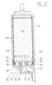
- FIG. 3 shows the package of FIG. 1 prior to filling
- FIG. 4 shows the package of FIG. 3 after filling
- FIG. 5 shows a longitudinal cross-section of a cartridge assembly with two packages of FIG. 4 in two different stages of dispensing
- FIGS. 6 - 8 each show a longitudinal cross-section of three different package assembly closures according to various embodiments of the present invention.
- FIG. 9 shows a variant of the cartridge assembly of FIG. 5 according to an embodiment of the present invention.
- FIG. 10 shows another cartridge assembly according to an embodiment of the present invention.
- FIG. 1 shows a longitudinal cross-section of a bottle shaped package assembly 1 having an integrally formed and seamless thin flexible wall 2 with an open neck end 3 passing through the inside of the tube 4 of a front outlet 5 , the flexible wall 2 being folded back over the front outside diameter of that tube 4 .
- a sealing ring 6 with lips 7 and 8 for sealing against the cartridge outlet, is fitted over the flexible wall 2 on the inside and outside of the tube 4 , the sealing ring 6 being formed to receive a separate sealing plug 9 .
- the package is made bottle shaped so as to essentially match the internal shape of a supporting structure before its insertion, such that it minimizes the necessary adjustment of the external shape of the package to that of the supporting structure which could otherwise lead to air induction into the package when the package is inserted inside the supporting structure and opened prior to dispensing. Furthermore, in comparison with the “state of the art” package which has two closed off ends, this aspect of the invention proposes a package assembly with only one closable open neck end, the open neck end having a reduced diameter with the advantage of the entire package wall having no wrinkles whatsoever.
- FIG. 2 Another aspect of the invention for a fabricated sausage type package according to FIG. 2, proposes the use of a compressible plug, rod or mushroom like device held within the closed wrinkled wall end such that the closure means, for instance a crimped ring, creates and maintains a compressive tension, the compressible device itself acting as an expanding and self adjusting sealing bung.
- the closure means for instance a crimped ring
- FIG. 2 shows a longitudinal cross-section of a package assembly 11 having a fabricated thin flexible wall 12 with two open ends, one being closed by a crimped ring 13 against a central compressible mushroom shaped device 14 .
- the open neck end 15 passes through the inside of the tube 4 of the front outlet 5 and is folded back over the front outside of tube 4 with a sealing ring fitted as similarly shown in FIG. 1.
- the membrane container wall comprises one or more layers of the same material or of different materials.
- FIG. 3 shows a longitudinal cross-section of a bottle shaped package assembly 1 , as shown in FIG. 1, with the rear part of the flexible membrane wall 2 having been folded over within itself and “outside-in” down to the inside of the front outlet 5 by a plunger 17 .
- This collapsed bottle shaped package within a rigid structure 60 is thus now ready for filling, the air previously contained within the package assembly having been evacuated by vacuum.
- FIG. 4 shows a longitudinal cross-section of the same package assembly 1 as in FIG. 3 but after filling with chemical 16 , and plugging.
- FIG. 5 shows a longitudinal cross-section of a cartridge assembly 18 which retains package assemblies 1 A and 1 B with chemical contents 16 A, 16 B within cylinders 20 A, 20 B and sealing those package assemblies 1 A and 1 B against cartridge outlet 21 via the sealing means 6 A, 6 B and lips 7 , 8 .
- Package assembly 1 A is shown with the driven piston 22 A, with lip 23 A, attached to the back of the package assembly 1 A and drive plunger 24 A, with drive rod 25 A, ready for forward movement.
- Package assembly 1 B is shown in a partly dispensed state with the driven piston 22 B, with lip 23 B, having been pushed down within the cylinder 20 B by the drive plunger 24 B and drive rod 25 B such that the package assembly 1 B has been turned “outside in” within itself while displacing the chemical content 16 B via the cartridge outlet 21 .
- FIG. 6 shows a longitudinal cross-section of a variation of a package assembly closure embodiment in the form of a package assembly sealing ring 6 , serving as a retaining means for the sealing and securing means of the membrane in the form of an O-ring 26 on the outside diameter of tube 4 which is provided with a groove 36 .
- the retaining ring 6 is also provided with a single sealing lip 8 and is closed off by a sealing plug 9 .
- FIG. 7 shows a similar package assembly closure embodiment as FIG. 6, with the exception of the inner part 39 of sealing ring 28 having an attached burstable or pierceable diaphragm 33 . It is evident that the sealing and securing O-ring stands for any appropriate sealing element.
- FIG. 8 shows a longitudinal cross-section of a variation of the package assembly closure embodiment of FIG. 6, in the form of a sealing ring 34 incorporating a spring loaded valve 41 which facilitates air free filling of the package and is opened by a pin 35 attached to the cartridge outlet.
- FIG. 9 shows one side only of a longitudinal cross-section of a cartridge assembly 18 similar to that shown in FIG. 5, in that it retains the package assembly 1 A with chemical contents 16 A within cylinder 20 A but with the variation that the neck of the membrane 2 A is sealed and secured on the outside of the tube 4 of the front outlet 5 A by O-ring 26 within an external groove 31 , the O-ring 26 being compressed against the cartridge outlet 21 so as to form a ring sealing means between that cartridge outlet 21 and the membrane 2 A. Also, the inside of the tube 4 is fitted with a closure having a burstable diaphragm 33 as shown in FIG. 7.
- FIG. 10 shows a longitudinal cross-section of one side of a cartridge assembly 58 which retains package assembly 42 A with chemical contents 16 A within the cartridge cylinder 43 A, the full diameter outlet end of container membrane 44 being secured and sealed between O-ring 45 and the O-ring groove 46 within the outer periphery 49 of the front outlet 47 , the securing O-ring 45 being retained by the retaining ring 48 against the outer periphery of the front outlet 47 .
- the wall 44 E of the membrane 44 is further sealed by the action of the pressure actuated lip 59 .
- Lip 59 can either press on the outlet end of cartridge cylinder wall 43 A or on its continuation, the wall of retaining ring 48 .
- the tube 51 of the front outlet 47 is closed by sealing ring 52 via O-ring 53 in groove 54 , the end 55 of the inner part 56 of sealing ring 52 having a burstable diaphragm 33 attached.
- the package assembly 42 A is shown sealed against the cartridge outlet 57 via the sealing ring means 52 with lips 7 A, 8 A.
- FIGS. 5, 9 and 10 all show a cartridge outlet 21 or 57 made in one piece, to which the individual front outlets 5 , 5 A, or 47 respectively are attached. This improves the handling and the assembly of such packages considerably, and also enables the easy use of, and attachment of a dynamic mixer.
- the embodiment with a sealing ring incorporating a spring loaded valve facilitates the container to be collapsed and evacuated, to maintain evacuation prior to air free filling, to maintain the filled condition without leakage, and allows for trouble free insertion into the supporting cartridge structure and connection to the cartridge outlet prior to use.
Abstract
A package assembly is provided for use within a reusable cartridge for dispensing at least one component. The package assembly includes a container with a thin, flexible membrane wall with an open end, and a front outlet to which the open end of the membrane container is secured by a ring-shaped sealing element. This membrane container outlet end allows conventional filling of the container and a perfect seal at the front outlet.
Description
- This application is a US national stage application of PCT Application PCT/EP99/07558, filed Oct. 10, 1999, claiming priority to European Application EP 988 11 014.4, filed Oct. 8, 1998.
- The use of two component cartridge systems is well known for the storage, metering and mixing of two component reactive chemical systems such as epoxies, polyurethanes, acrylics, silicones, polysulfides and polyesters. It is also well known that, for environmental reasons, cartridge systems including sausage type packages with thin plastic/foil laminate membrane walls are used to contain such chemicals. These packages are fitted within and supported by a cartridge like structure while the contents are dispensed. When depleted, the sausage type packages may be disposed of, while the whole (or majority) of the supporting cartridge structure can be reused.
- It is within this field of sausage type package use that certain problems are seen to arise. For example, U.S. Pat. Nos. 5,332,122 and 5,501,368 teach containers for flowable substances. These containers require packages fabricated from flexible plastic foil/laminate sheets. For a given package, the flexible plastic foil/laminate sheet is folded to form a tube and then partially overlapped and welded together such that, along the weld length, the now double layer seam is thicker and less flexible than the rest of the package wall and is subject to potential leakage due to weld failure. Moreover, the aforementioned container tube fabrication takes place as the first stage of a complex and continuous fabrication, filling and closing process, the process continues after the initial closing of the tube with the immediate chemical filling of the tube as the second stage. The third stage involves the dividing off and closing of the, now, filled tube into volumetrically controlled lengths. At the division points, the filled tube diameter is reduced all the way to the tube axis, which results in considerable wrinkling of the tube wall prior to being closed by a crimped ring. Such crimped ring closures often fail to achieve an effective seal due to the incompressibility of the membrane and of the wrinkled overlaps which, themselves, tend to form leak paths under pressure. For the same reasons, the necessary sealing of the wrinkled tube wall against a front outlet is another failure area.
- In addition, at a time just prior to the package use and after it has been placed within a reusable cartridge support structure, the package outlet end must be opened. This is done by cutting behind the crimped ring closure of the package. This opening of the package outlet end allows the package to settle within the reusable cartridge, adjusting its outer shape to conform to that of the internal diameter of the supporting structure. In doing so, air is induced into the package, particularly with lower viscosity chemicals. Thus, as air within a metering package causes the content to be non-hydraulic and therefore compressible, both the start and the stop of each of the two metered flows go out of synchronization relative to each other, which can result in an “off ratio” mixture when being processed through a static mixer. Furthermore, at the end of the discharge stroke, this can also lead to an unacceptable residual volume of chemical left within the center of the collapsed package due to incomplete compaction as a result of the membrane having been scraped off the outer supporting structure wall, folded and compacted in a more or less ring shaped fashion.
- Alternatively, if a fabricated membrane container with a longitudinal seam is used for a package, problems arise in particular at the outlet of the package. One proposal, according to U.S. Pat. No. 5,647,510, provides, at the outlet end, an outlet piece to which the straight end of the membrane container wall is adhered. This adhesion process, however, is difficult to achieve in a leak proof and reliable fashion.
- Starting from the aforementioned prior art, it is an object of the present invention to provide a thin wall membrane package which overcomes the above mentioned drawbacks, and provides a proper sealing and closure of the outlet end.
- A further object is to avoid the problems arising from the fabricated sausage type package with longitudinal seams and a rear end closure. Thus, according to one aspect of the present invention, a package assembly is provided including an integrally formed, uniform and seamless thin flexible membrane wall container so as to avoid any chance of seam joint or rear end closure failure.
- A further object is to provide for a package with easy handling and assembling properties and which improves, in particular, the attachment of a dynamic mixer.
- Above all, another aspect of the present invention is directed at improving and/or eliminating the highly complex and necessarily combined fabrication and filling process, which entails high initial capital investment and is only economically viable for long production runs that can absorb the high “setting up” costs prior to each production run. Hence, an environmentally advantageous package is proposed with the major advantages of being fillable by existing conventional cartridge filling methods, yet avoiding the entrapment of air within the liquid chemical content.
- Preferred embodiments of the invention will now be described in detail by reference to the accompanying drawing. Wherever possible, the same reference numbers will be used throughout the drawings to refer to the same or like parts.
- FIG. 1 shows a longitudinal cross-section of a package according to a first embodiment of the invention;
- FIG. 2 shows a longitudinal cross-section of a package according to a second embodiment of the invention;
- FIG. 3 shows the package of FIG. 1 prior to filling;
- FIG. 4 shows the package of FIG. 3 after filling;
- FIG. 5 shows a longitudinal cross-section of a cartridge assembly with two packages of FIG. 4 in two different stages of dispensing;
- FIGS. 6-8 each show a longitudinal cross-section of three different package assembly closures according to various embodiments of the present invention;
- FIG. 9 shows a variant of the cartridge assembly of FIG. 5 according to an embodiment of the present invention; and
- FIG. 10 shows another cartridge assembly according to an embodiment of the present invention.
- FIG. 1 shows a longitudinal cross-section of a bottle
shaped package assembly 1 having an integrally formed and seamless thinflexible wall 2 with anopen neck end 3 passing through the inside of thetube 4 of afront outlet 5, theflexible wall 2 being folded back over the front outside diameter of thattube 4. Asealing ring 6, withlips flexible wall 2 on the inside and outside of thetube 4, the sealingring 6 being formed to receive aseparate sealing plug 9. - It follows from the above that the package is made bottle shaped so as to essentially match the internal shape of a supporting structure before its insertion, such that it minimizes the necessary adjustment of the external shape of the package to that of the supporting structure which could otherwise lead to air induction into the package when the package is inserted inside the supporting structure and opened prior to dispensing. Furthermore, in comparison with the “state of the art” package which has two closed off ends, this aspect of the invention proposes a package assembly with only one closable open neck end, the open neck end having a reduced diameter with the advantage of the entire package wall having no wrinkles whatsoever.
- Another aspect of the invention for a fabricated sausage type package according to FIG. 2, proposes the use of a compressible plug, rod or mushroom like device held within the closed wrinkled wall end such that the closure means, for instance a crimped ring, creates and maintains a compressive tension, the compressible device itself acting as an expanding and self adjusting sealing bung.
- FIG. 2 shows a longitudinal cross-section of a
package assembly 11 having a fabricated thinflexible wall 12 with two open ends, one being closed by a crimpedring 13 against a central compressible mushroom shapeddevice 14. At the front of thepackage assembly 11, theopen neck end 15 passes through the inside of thetube 4 of thefront outlet 5 and is folded back over the front outside oftube 4 with a sealing ring fitted as similarly shown in FIG. 1. - According to the characteristics of the chemicals to be stored in the containers, the membrane container wall comprises one or more layers of the same material or of different materials.
- FIG. 3 shows a longitudinal cross-section of a bottle
shaped package assembly 1, as shown in FIG. 1, with the rear part of theflexible membrane wall 2 having been folded over within itself and “outside-in” down to the inside of thefront outlet 5 by aplunger 17. This collapsed bottle shaped package within arigid structure 60 is thus now ready for filling, the air previously contained within the package assembly having been evacuated by vacuum. - FIG. 4 shows a longitudinal cross-section of the
same package assembly 1 as in FIG. 3 but after filling withchemical 16, and plugging. - FIG. 5 shows a longitudinal cross-section of a
cartridge assembly 18 which retainspackage assemblies chemical contents cylinders package assemblies cartridge outlet 21 via the sealing means 6A, 6B andlips Package assembly 1A is shown with the drivenpiston 22A, withlip 23A, attached to the back of thepackage assembly 1A and driveplunger 24A, withdrive rod 25A, ready for forward movement.Package assembly 1B is shown in a partly dispensed state with the drivenpiston 22B, withlip 23B, having been pushed down within thecylinder 20B by thedrive plunger 24B and driverod 25B such that thepackage assembly 1B has been turned “outside in” within itself while displacing thechemical content 16B via thecartridge outlet 21. - FIG. 6 shows a longitudinal cross-section of a variation of a package assembly closure embodiment in the form of a package
assembly sealing ring 6, serving as a retaining means for the sealing and securing means of the membrane in the form of an O-ring 26 on the outside diameter oftube 4 which is provided with agroove 36. Theretaining ring 6 is also provided with asingle sealing lip 8 and is closed off by asealing plug 9. - FIG. 7 shows a similar package assembly closure embodiment as FIG. 6, with the exception of the
inner part 39 ofsealing ring 28 having an attached burstable orpierceable diaphragm 33. It is evident that the sealing and securing O-ring stands for any appropriate sealing element. - FIG. 8 shows a longitudinal cross-section of a variation of the package assembly closure embodiment of FIG. 6, in the form of a sealing ring 34 incorporating a spring loaded
valve 41 which facilitates air free filling of the package and is opened by apin 35 attached to the cartridge outlet. - FIG. 9 shows one side only of a longitudinal cross-section of a
cartridge assembly 18 similar to that shown in FIG. 5, in that it retains thepackage assembly 1A withchemical contents 16A withincylinder 20A but with the variation that the neck of themembrane 2A is sealed and secured on the outside of thetube 4 of thefront outlet 5A by O-ring 26 within anexternal groove 31, the O-ring 26 being compressed against thecartridge outlet 21 so as to form a ring sealing means between thatcartridge outlet 21 and themembrane 2A. Also, the inside of thetube 4 is fitted with a closure having aburstable diaphragm 33 as shown in FIG. 7. - FIG. 10 shows a longitudinal cross-section of one side of a
cartridge assembly 58 which retainspackage assembly 42A withchemical contents 16A within thecartridge cylinder 43A, the full diameter outlet end ofcontainer membrane 44 being secured and sealed between O-ring 45 and the O-ring groove 46 within theouter periphery 49 of thefront outlet 47, the securing O-ring 45 being retained by the retainingring 48 against the outer periphery of thefront outlet 47. In addition, under operating conditions, thewall 44E of themembrane 44 is further sealed by the action of the pressure actuatedlip 59.Lip 59 can either press on the outlet end ofcartridge cylinder wall 43A or on its continuation, the wall of retainingring 48. - The tube 51 of the
front outlet 47 is closed by sealingring 52 via O-ring 53 ingroove 54, the end 55 of theinner part 56 of sealingring 52 having aburstable diaphragm 33 attached. Thepackage assembly 42A is shown sealed against thecartridge outlet 57 via the sealing ring means 52 withlips - It follows that a sealed outlet closure is achieved regardless of whether the flexible membrane wall is seamless or not, or whether the container is bottle-shaped or not. The proposed method and the closure means allow also the filling of the container without any air inclusion.
- The embodiments of FIGS. 5, 9 and 10 all show a
cartridge outlet individual front outlets - The embodiment with a sealing ring incorporating a spring loaded valve facilitates the container to be collapsed and evacuated, to maintain evacuation prior to air free filling, to maintain the filled condition without leakage, and allows for trouble free insertion into the supporting cartridge structure and connection to the cartridge outlet prior to use.
Claims (23)
1. A reusable cartridge assembly for dispensing at least one component, comprising at least one cartridge cylinder (20A, 20B, 43A) having a rigid wall, a cartridge outlet and a package assembly (1A, 1B, 42A), the package assembly comprising a container having a thin, flexible membrane wall with an open end, characterized in that the package assembly (1, 1A, 1B, 11, 42A) further comprises a front outlet (5, 5A; 47) to which the open end (3, 15, 44E) of the flexible membrane wall (2, 2A, 12, 44) is secured by a ring-shaped sealing element (6, 6A, 6B, 34) or by a ring-shaped sealing element (26, 45) retained by a retaining means (6, 28, 48).
2. A reusable cartridge assembly for dispensing at least one component, comprising at least one cartridge cylinder (20A, 20B, 43A) having a rigid wall, a cartridge outlet and a package assembly (1A, 1B, 42A), the package assembly comprising a container having a thin, flexible membrane wall with an open end, characterized in that the thin, flexible membrane wall (2, 2A, 44A) of the container (1, 1A, 1B, 42A, is integrally formed and seamless.
3. A cartridge assembly according to claim 1 , characterized in that the container has a fabricated, thin, flexible membrane wall (12) with a closed end (13, 14) and an open end (15).
4. A cartridge assembly according to claim 2 , characterized in that the open end (3, 44E) of the membrane container (2, 2A, 44A) is secured to the front outlet (5, 47) by a ring-shaped sealing element (6, 6A, 6B, 34) or by a ring-shaped sealing element (26, 45) retained by a retaining means (6, 28, 48).
5. A cartridge assembly according to any of claims 1 to 4 , characterized in that the membrane container is made with an open neck end (3, 15), the external shape of which essentially matches the internal shape of a supporting structure.
6. A cartridge assembly according to claim 5 , characterized in that the membrane container is bottle shaped and has a closure element (9, 33, 41).
7. A cartridge assembly according to claim 5 or 6, characterized in that the front outlet (5) of the package comprises a tube (4) having as a ring shaped sealing element a sealing ring (6, 6A, 6B, 28, 34) fitted around the outlet end of the tube for attaching and sealing the open neck end (3, 15).
8. A cartridge assembly according to any of claims 1 to 6 , characterized in that the open neck end (3, 15) of the membrane wall is secured in a groove (31, 36) at the outer diameter of the front outlet tube (4) by a ring shaped sealing element (26) retained by the sealing ring (6, 28) or by the bore of the cartridge outlet (21).
9. A cartridge assembly according to any of claims 1 to 4 , characterized in that the end of membrane wall (44E) is secured in a groove (46) at the periphery of the front outlet (47) by the sealing element (45) retained by the retaining ring (48).
10. A cartridge assembly according to claim 9 , characterized in that the front outlet (47) comprises a sealing lip (59), sealing the membrane wall (44) against the cartridge wall (43A) or the sealing ring (48).
11. A cartridge assembly according to claim 9 or 10, characterized in that the front outlet (47) comprises a tube (51) and a sealing ring (52) fitted around the tube having a closure element (9, 33, 41).
12. A cartridge assembly according to any of claims 1 to 11 , characterized in that the sealing ring (6, 6A, 6B, 28, 34, 52) is provided with at least one sealing lip (7, 7A, 8, 8A) at its outer diameter.
13. A cartridge assembly according to claim 2 , characterized in that the integral membrane container has at least one additional membrane layer.
14. A cartridge assembly according to any of claims 1 to 13 , characterized in that the front outlet tube (4, 51) comprises a closure having a burstable or pierceable diaphragm (33).
15. A cartridge assembly according to any of claims 1 to 14 , characterized in that the front outlet tube (4, 51) is closed by a sealing plug (9).
16. A cartridge assembly according to any of claims 1 to 14 , characterized in that the front outlet tube (4, 51) is closed by a self closing valve (41).
17. A cartridge assembly according to any of claims 1, 3, 5 to 15, characterized in that the closed back end of the membrane container (12) has, at it's center, a compressible plug (14) and a closure element (13) over it's outer diameter.
18. A cartridge assembly according to claim 17 , characterized in that the compressible plug (14) has an increased diameter on at least one of it≡s ends.
19. A cartridge assembly according to any one of claims 1 to 18 , characterized in that the cartridge outlet (21, 57) is made in one piece for receiving the individual front outlets (5, 5A, 47) of the package assembly.
20. A cartridge assembly according to any one of claims 1 to 19 , characterized in that the sealing lips (7, 7A, 8, 8A) of the sealing ring (6, 6A, 6B, 28, 34, 52) or the sealing element (26) are sealing within the bore of the cartridge outlet (21, 57).
21. A cartridge assembly according to any of claims 1 to 20 , characterized in that the cartridge assembly further comprises a driven piston (22A, 22B), the piston and the piston side ends of the wall of the cartridge cylinder being arranged such that the membrane container is turned “outside in” by the action of the piston.
22. A cartridge assembly according to any of claims 1 to 21 , characterized in that the cartridge outlet (21, 57) comprises a pin (35) for opening the self closing valve (41).
23. A method for filling the package assembly according to any of claims 1-22, characterized in that, prior to filling, the membrane container having an open front end is turned “outside in”, then vacuum is applied at the outlet end for complete air evacuation, whereupon the membrane container package is filled with the chemical content free of air and closed by the outlet closure elements.
Priority Applications (1)
| Application Number | Priority Date | Filing Date | Title |
|---|---|---|---|
| US10/429,870 US6766921B2 (en) | 1998-10-09 | 2003-05-06 | Thin wall package for use within a reusable cartridge |
Applications Claiming Priority (5)
| Application Number | Priority Date | Filing Date | Title |
|---|---|---|---|
| EPEP98811014.4 | 1998-10-09 | ||
| EP19980811014 EP0992438A1 (en) | 1998-10-09 | 1998-10-09 | Thin wall cartridge for use within a reusable dispenser |
| EP98811014 | 1998-10-09 | ||
| US09/821,467 US6578738B1 (en) | 1998-10-09 | 1999-10-08 | Thin wall package for use within a reusable cartridge |
| US10/429,870 US6766921B2 (en) | 1998-10-09 | 2003-05-06 | Thin wall package for use within a reusable cartridge |
Related Parent Applications (2)
| Application Number | Title | Priority Date | Filing Date |
|---|---|---|---|
| US09/821,467 Continuation US6578738B1 (en) | 1998-10-09 | 1999-10-08 | Thin wall package for use within a reusable cartridge |
| PCT/EP1999/007558 Continuation WO2000021858A1 (en) | 1998-10-09 | 1999-10-08 | Thin wall package for use within a reusable cartridge |
Publications (2)
| Publication Number | Publication Date |
|---|---|
| US20030197022A1 true US20030197022A1 (en) | 2003-10-23 |
| US6766921B2 US6766921B2 (en) | 2004-07-27 |
Family
ID=8236379
Family Applications (2)
| Application Number | Title | Priority Date | Filing Date |
|---|---|---|---|
| US09/821,467 Expired - Lifetime US6578738B1 (en) | 1998-10-09 | 1999-10-08 | Thin wall package for use within a reusable cartridge |
| US10/429,870 Expired - Lifetime US6766921B2 (en) | 1998-10-09 | 2003-05-06 | Thin wall package for use within a reusable cartridge |
Family Applications Before (1)
| Application Number | Title | Priority Date | Filing Date |
|---|---|---|---|
| US09/821,467 Expired - Lifetime US6578738B1 (en) | 1998-10-09 | 1999-10-08 | Thin wall package for use within a reusable cartridge |
Country Status (7)
| Country | Link |
|---|---|
| US (2) | US6578738B1 (en) |
| EP (3) | EP0992438A1 (en) |
| JP (1) | JP4246920B2 (en) |
| AU (1) | AU6336399A (en) |
| DE (2) | DE69933399T2 (en) |
| ES (2) | ES2203187T3 (en) |
| WO (1) | WO2000021858A1 (en) |
Cited By (6)
| Publication number | Priority date | Publication date | Assignee | Title |
|---|---|---|---|---|
| WO2006120480A3 (en) * | 2005-05-06 | 2007-01-11 | Stuart Edward Saunders | Tiling adhesive applicator |
| WO2012152928A1 (en) * | 2011-05-11 | 2012-11-15 | Poly-Clip System Gmbh & Co. Kg | Assembling apparatus, assembling method and packaging combination |
| DE102012101503A1 (en) | 2012-02-24 | 2013-08-29 | Krones Ag | Removal device for removing liquids from containers |
| US20190177014A1 (en) * | 2017-12-08 | 2019-06-13 | Nordson Corporation | Flexible package filling technique |
| US10434528B1 (en) | 2018-10-02 | 2019-10-08 | Sulzer Mixpac Ag | Cartridge, dispensing assembly and method of manufacturing a cartridge |
| US20220023896A1 (en) * | 2020-07-24 | 2022-01-27 | Albion Engineering Company | Common head having an offset partition for use with multi-component dispensing tools and a tubular liner arranged for locating within the common head |
Families Citing this family (53)
| Publication number | Priority date | Publication date | Assignee | Title |
|---|---|---|---|---|
| AU2002233253A1 (en) * | 2000-12-21 | 2002-07-01 | Wacker-Chemie G.M.B.H. | Dosing device attachment |
| GB0206343D0 (en) * | 2002-03-18 | 2002-05-01 | Cussons Int Ltd | Fluid dispenser |
| JP4006332B2 (en) * | 2002-12-26 | 2007-11-14 | 勝利 増田 | Fluid storage container |
| JP4391162B2 (en) | 2003-08-26 | 2009-12-24 | 株式会社細川洋行 | Liquid container pouring device and bag-in-box |
| US20100108709A1 (en) * | 2004-12-30 | 2010-05-06 | Plas-Pak Industries | Cartridge delivery system utilizing film bags |
| WO2007060537A2 (en) * | 2005-11-25 | 2007-05-31 | Di.Gi. Costruzioni Meccaniche S.R.L. | A device for dispensing adhesive to planar surfaces, in particular tiles, an automatic machine for applying adhesive to planar surfaces and an adhesive cartridge |
| GB0602340D0 (en) * | 2006-02-07 | 2006-03-15 | Rawlplug Co Ltd | Nozzle and/or adaptor unit on cartridge |
| DE102006040507A1 (en) * | 2006-03-10 | 2007-09-13 | Tremco Illbruck Productie B.V. | Silicone cartridge`s content color adjustment method for use in catridge pistol, involves allowing colorless silicone from container and coloring material to intersperse in common mixing chamber, before mixture is brought into cartridge |
| US8627980B2 (en) | 2006-04-11 | 2014-01-14 | Tony Woodruff | Enclosed bathtub liner |
| KR101515647B1 (en) * | 2006-12-15 | 2015-04-27 | 쓰리엠 이노베이티브 프로퍼티즈 컴파니 | Mixing and dispensing curable multi-component materials |
| US20080142546A1 (en) * | 2006-12-15 | 2008-06-19 | Conopco, Inc., D/B/A Unilever | Package |
| DE502007001725D1 (en) | 2007-01-23 | 2009-11-26 | Hans Georg Hagleitner | Made of a flexible material web of weldable plastic container |
| WO2008135714A1 (en) * | 2007-05-03 | 2008-11-13 | Stephen Walker | Dispensing device and method of use thereof |
| US8906187B2 (en) * | 2008-06-25 | 2014-12-09 | Colgate-Palmolive Company | Method of making shoulder/nozzles with film barrier liners |
| IT1393823B1 (en) * | 2009-04-20 | 2012-05-11 | Lumson Spa | DEVICE FOR CONTAINING WITH AIR HOLDING AND TO SUPPLY FLUID SUBSTANCES |
| US20110121028A1 (en) * | 2009-05-13 | 2011-05-26 | Server Products, Inc. | Dispenser and flexible pouch for liquid food product |
| WO2012007771A2 (en) | 2010-07-16 | 2012-01-19 | Mcgill Technology Limited | Dispensing apparatus |
| US9498570B2 (en) | 2010-10-25 | 2016-11-22 | Bayer Healthcare Llc | Bladder syringe fluid delivery system |
| WO2012061140A1 (en) | 2010-10-25 | 2012-05-10 | Medrad, Inc. | Bladder syringe fluid delivery system |
| WO2012068092A2 (en) | 2010-11-15 | 2012-05-24 | Milwaukee Electric Tool Corporation | Powered dispensing tool |
| WO2012067801A1 (en) | 2010-11-15 | 2012-05-24 | Milwaukee Electric Tool Corporation | Powered dispensing tool |
| DE102011007475A1 (en) * | 2011-04-15 | 2012-10-18 | Hilti Aktiengesellschaft | Film cartridge and method for producing a film cartridge |
| US8857672B2 (en) | 2011-06-20 | 2014-10-14 | Milwaukee Electric Tool Corporation | Carriage assembly for dispensing tool |
| US9039557B2 (en) | 2011-09-02 | 2015-05-26 | Milwaukee Electric Tool Corporation | Powered dispensing tool |
| DE102012101868A1 (en) * | 2012-03-06 | 2013-09-12 | Krones Ag | Method for filling a container and fillable container |
| US9180252B2 (en) | 2012-04-20 | 2015-11-10 | Bayer Medical Care Inc. | Bellows syringe fluid delivery system |
| DE102012220790A1 (en) * | 2012-11-14 | 2014-05-15 | Henkel Ag & Co. Kgaa | Container for dispensing a multi-component mixture |
| US9597706B2 (en) | 2013-03-15 | 2017-03-21 | Rooftop Research, Llc | Container and substance dispensing system |
| US9814871B2 (en) | 2013-03-15 | 2017-11-14 | Bayer Healthcare Llc | Connector assembly for syringe system |
| DE102013109378A1 (en) * | 2013-08-29 | 2015-03-05 | Krones Ag | Process for the manufacture of containers filled with a liquid |
| DE102013222111A1 (en) | 2013-10-30 | 2015-04-30 | Henkel Ag & Co. Kgaa | Dynamic mixing device |
| EP2927156A1 (en) * | 2014-03-31 | 2015-10-07 | Sulzer Mixpac AG | Cartridge and method for producing a cartridge |
| CA2946838C (en) | 2014-04-25 | 2023-04-04 | Bayer Healthcare Llc | Syringe with rolling diaphragm |
| US20180029067A1 (en) * | 2015-02-06 | 2018-02-01 | Cryovac, Inc. | Dispensing System, Packaging System, Package, Dispensing Assembly, And Method Of Dispensing A Product |
| WO2016172467A1 (en) | 2015-04-24 | 2016-10-27 | Bayer Healthcare Llc | Syringe with rolling diaphragm |
| AR106795A1 (en) | 2015-11-25 | 2018-02-21 | Bayer Healthcare Llc | SYRINGE AND CONNECTOR SYSTEM |
| EP3263483A1 (en) * | 2016-07-01 | 2018-01-03 | Sulzer Mixpac AG | Cartridge, core, mold and method of manufacturing a cartridge |
| CN109689129B (en) | 2016-09-16 | 2022-04-19 | 拜耳医药保健有限公司 | Pressure jacket with syringe retaining element |
| JP7023947B2 (en) | 2016-10-17 | 2022-02-22 | バイエル・ヘルスケア・エルエルシー | Fluid injector with syringe engagement mechanism |
| EP3525839B1 (en) | 2016-10-17 | 2021-12-29 | Bayer Healthcare LLC | Fluid injector with syringe engagement mechanism |
| CN106742217B (en) * | 2016-12-14 | 2019-11-12 | 江苏创景科技有限公司 | A kind of sealant packing method and sealant packaging structure |
| ES2904369T3 (en) | 2017-09-13 | 2022-04-04 | Bayer Healthcare Llc | Sliding syringe cap for separate filling and dispensing |
| DK3486076T3 (en) * | 2017-11-20 | 2023-11-27 | Coexpair S A | RESIN TRANSFER MOLDING (RTM) RESIN TRANSFER SYSTEM AND RELATED METHOD |
| US10968031B2 (en) | 2017-12-27 | 2021-04-06 | Sulzer Mixpac Ag | Piston for a collapsible cartridge |
| EP3632575A1 (en) * | 2018-10-02 | 2020-04-08 | Sulzer Mixpac AG | Reusable cartridge piston |
| EP3632818A1 (en) * | 2018-10-02 | 2020-04-08 | Sulzer Mixpac AG | Cartridge, dispensing assembly and method of manufacturing a cartridge |
| JP7292380B2 (en) * | 2018-10-02 | 2023-06-16 | メドミクス スウィッツァランド アーゲー | Cartridge, method of manufacturing cartridge, dispensing assembly, and method of assembling dispensing assembly |
| BR112021005499A2 (en) * | 2018-10-02 | 2021-06-15 | Sulzer Mixpac Ag | cartridge, dispensing assembly and method of manufacturing a cartridge |
| US20200230636A1 (en) * | 2019-01-18 | 2020-07-23 | Rooftop Research, Llc | Fluid Dispensing System |
| WO2021023571A1 (en) * | 2019-08-02 | 2021-02-11 | Sulzer Mixpac Ag | Cartridge assembly, sleeve, system and method of assembling a cartridge assembly |
| EP4028077A1 (en) | 2019-09-10 | 2022-07-20 | Bayer HealthCare LLC | Pressure jackets and syringe retention features for angiography fluid injectors |
| CN115151298A (en) | 2020-02-21 | 2022-10-04 | 拜耳医药保健有限责任公司 | Fluid path connector for medical fluid delivery |
| CN115697435A (en) | 2020-06-18 | 2023-02-03 | 拜耳医药保健有限责任公司 | Online bubble suspension device for angiographic injector fluid path |
Citations (4)
| Publication number | Priority date | Publication date | Assignee | Title |
|---|---|---|---|---|
| US5292034A (en) * | 1990-03-26 | 1994-03-08 | Aisa Automation Industrielle Sa | Method for the production of a tube with a multi-layer tube head and a tube made of a pipe element having at least one plastic layer and a multi-layer tube head |
| US5480067A (en) * | 1993-04-14 | 1996-01-02 | Hilti Aktiengesellschaft | Composite foil hose-shaped bag |
| US5593066A (en) * | 1992-12-22 | 1997-01-14 | Kabushiki Kaisha Hosokawa Yoko | Container, method of manufacturing the same, and installation jig for cartridge container for discharge gun |
| US5656346A (en) * | 1991-01-21 | 1997-08-12 | Kmk Lizence Ltd. | Packaging tube |
Family Cites Families (18)
| Publication number | Priority date | Publication date | Assignee | Title |
|---|---|---|---|---|
| FR1162955A (en) * | 1955-09-12 | 1958-09-19 | Method of adapting a plastic neck to the opening of a bag or sachet of the same material to obtain a bottle | |
| US3552607A (en) * | 1968-07-08 | 1971-01-05 | Techs Inc | Pour-spout closure for plastic container |
| FR2067177A1 (en) * | 1969-11-21 | 1971-08-20 | Rodriguez Julian | |
| FR2411140A2 (en) * | 1977-12-07 | 1979-07-06 | Seppic Sa | Fluid dispenser and distributor - has deformable reservoir contained in valved dispenser usable to pump fluid from reservoir |
| FR2483881A3 (en) * | 1980-06-09 | 1981-12-11 | Scholle Corp | Filler for flexible plastics bags - has bags enclosed in boxes and mounted on scissor lift filled from head through holes in bags |
| US4469250A (en) * | 1982-02-25 | 1984-09-04 | Nick Sekich, Jr. | Squeezable dispensing apparatus and method of operation |
| US5118003A (en) * | 1989-06-26 | 1992-06-02 | Bemis Manufacturing Company | Vacuum drainage collecting device |
| US5033631A (en) * | 1990-02-08 | 1991-07-23 | Harold Nightingale | Method and apparatus for expelling air from a flexible liner baby nursing bottle |
| US5037002A (en) * | 1990-07-11 | 1991-08-06 | Liqui-Box/B-Bar-B Corporation | Integral self-supporting and recyclable liquid container |
| US5135137A (en) * | 1991-01-17 | 1992-08-04 | The Coca-Cola Company | Simplified micro-gravity pre-mix package |
| DE9200521U1 (en) | 1991-11-12 | 1993-03-25 | Thera Patent Gmbh & Co Kg Gesellschaft Fuer Industrielle Schutzrechte, 8031 Seefeld, De | |
| DE4306206A1 (en) | 1993-03-01 | 1994-09-08 | Wirtgen Gmbh | Milling-cutter arrangement for road-milling machines |
| DE4403755A1 (en) * | 1993-05-05 | 1994-11-10 | Pfeiffer Erich Gmbh & Co Kg | Discharge device for media |
| DE69415293T2 (en) | 1993-08-20 | 1999-05-06 | Wilhelm A Keller | MULTI-COMPONENT MEASURING AND DOSING DEVICE WITH FOLDING CARTRIDGE |
| DE9400524U1 (en) | 1994-01-13 | 1995-05-18 | Thera Ges Fuer Patente | Device for emptying a tubular bag |
| DE69415310T2 (en) * | 1994-07-18 | 1999-04-29 | Wilhelm A Keller | Cartridge with exchangeable inner packaging |
| US5699935A (en) * | 1996-01-18 | 1997-12-23 | The Procter & Gamble Company | Inverting bag co-dispenser |
| DE69733800T2 (en) * | 1996-12-24 | 2006-04-06 | Mixpac Systems Ag | Device and cartridge for an evertable tubular bag |
-
1998
- 1998-10-09 EP EP19980811014 patent/EP0992438A1/en not_active Withdrawn
-
1999
- 1999-10-08 EP EP19990950677 patent/EP1121308B1/en not_active Expired - Lifetime
- 1999-10-08 ES ES99950677T patent/ES2203187T3/en not_active Expired - Lifetime
- 1999-10-08 US US09/821,467 patent/US6578738B1/en not_active Expired - Lifetime
- 1999-10-08 EP EP20030007870 patent/EP1350736B1/en not_active Expired - Lifetime
- 1999-10-08 DE DE1999633399 patent/DE69933399T2/en not_active Expired - Lifetime
- 1999-10-08 DE DE1999609115 patent/DE69909115T2/en not_active Expired - Lifetime
- 1999-10-08 AU AU63363/99A patent/AU6336399A/en not_active Abandoned
- 1999-10-08 ES ES03007870T patent/ES2271412T3/en not_active Expired - Lifetime
- 1999-10-08 WO PCT/EP1999/007558 patent/WO2000021858A1/en active IP Right Grant
- 1999-10-08 JP JP2000575777A patent/JP4246920B2/en not_active Expired - Fee Related
-
2003
- 2003-05-06 US US10/429,870 patent/US6766921B2/en not_active Expired - Lifetime
Patent Citations (4)
| Publication number | Priority date | Publication date | Assignee | Title |
|---|---|---|---|---|
| US5292034A (en) * | 1990-03-26 | 1994-03-08 | Aisa Automation Industrielle Sa | Method for the production of a tube with a multi-layer tube head and a tube made of a pipe element having at least one plastic layer and a multi-layer tube head |
| US5656346A (en) * | 1991-01-21 | 1997-08-12 | Kmk Lizence Ltd. | Packaging tube |
| US5593066A (en) * | 1992-12-22 | 1997-01-14 | Kabushiki Kaisha Hosokawa Yoko | Container, method of manufacturing the same, and installation jig for cartridge container for discharge gun |
| US5480067A (en) * | 1993-04-14 | 1996-01-02 | Hilti Aktiengesellschaft | Composite foil hose-shaped bag |
Cited By (12)
| Publication number | Priority date | Publication date | Assignee | Title |
|---|---|---|---|---|
| WO2006120480A3 (en) * | 2005-05-06 | 2007-01-11 | Stuart Edward Saunders | Tiling adhesive applicator |
| US20090266295A1 (en) * | 2005-05-06 | 2009-10-29 | Stuart Edward Saunders | Tiling adhesive applicator |
| WO2012152928A1 (en) * | 2011-05-11 | 2012-11-15 | Poly-Clip System Gmbh & Co. Kg | Assembling apparatus, assembling method and packaging combination |
| US9764865B2 (en) | 2011-05-11 | 2017-09-19 | Poly-Clip System Gmbh & Co. Kg | Assembling apparatus, assembling method and packaging combination |
| DE102012101503A1 (en) | 2012-02-24 | 2013-08-29 | Krones Ag | Removal device for removing liquids from containers |
| WO2013124486A1 (en) | 2012-02-24 | 2013-08-29 | Krones Ag | Removal device for removing liquids from containers |
| US20190177014A1 (en) * | 2017-12-08 | 2019-06-13 | Nordson Corporation | Flexible package filling technique |
| CN111448139A (en) * | 2017-12-08 | 2020-07-24 | 诺信公司 | Flexible package filling technique |
| US10906673B2 (en) * | 2017-12-08 | 2021-02-02 | Nordson Corporation | Method and apparatus for filling a flexible film bag attached to a face plate |
| US10434528B1 (en) | 2018-10-02 | 2019-10-08 | Sulzer Mixpac Ag | Cartridge, dispensing assembly and method of manufacturing a cartridge |
| US20220023896A1 (en) * | 2020-07-24 | 2022-01-27 | Albion Engineering Company | Common head having an offset partition for use with multi-component dispensing tools and a tubular liner arranged for locating within the common head |
| US11896993B2 (en) * | 2020-07-24 | 2024-02-13 | Albion Engineering Company | Common head having an offset partition for use with multi-component dispensing tools and a tubular liner arranged for locating within the common head |
Also Published As
| Publication number | Publication date |
|---|---|
| DE69909115D1 (en) | 2003-07-31 |
| EP1350736A1 (en) | 2003-10-08 |
| ES2271412T3 (en) | 2007-04-16 |
| EP1350736B1 (en) | 2006-09-27 |
| ES2203187T3 (en) | 2004-04-01 |
| EP1121308B1 (en) | 2003-06-25 |
| WO2000021858A1 (en) | 2000-04-20 |
| US6766921B2 (en) | 2004-07-27 |
| AU6336399A (en) | 2000-05-01 |
| US6578738B1 (en) | 2003-06-17 |
| DE69933399T2 (en) | 2007-07-19 |
| EP1121308A1 (en) | 2001-08-08 |
| JP2002527310A (en) | 2002-08-27 |
| DE69909115T2 (en) | 2003-12-24 |
| EP0992438A1 (en) | 2000-04-12 |
| DE69933399D1 (en) | 2006-11-09 |
| JP4246920B2 (en) | 2009-04-02 |
Similar Documents
| Publication | Publication Date | Title |
|---|---|---|
| US6578738B1 (en) | Thin wall package for use within a reusable cartridge | |
| US5343901A (en) | Insertable barrier bag or liner for a narrow neck dispensing container and method of filling such a barrier bag or liner | |
| US6634524B1 (en) | Two-component cartridge for free-flowing media | |
| US5505039A (en) | Method of filling and pressurizing a container | |
| US3828977A (en) | Compartment bag assembly for dispensing containers | |
| US3548564A (en) | Process for fabricating a pressurized container | |
| US4556156A (en) | Pressurized dispensing apparatus | |
| US5522526A (en) | Method and device for dispensing and packaging a fluid product contained in a receptacle which is pressurized with the aid of a propellant gas | |
| US4896794A (en) | Method for prepressurizing dispensing container and for filling pressurized container with flowable product | |
| EP0695269A1 (en) | Device for transferring media | |
| WO1994016951B1 (en) | Method and apparatus for packaging, mixing and delivering bone cement | |
| US5865351A (en) | Pressurized device for the dispensing of liquid of creamy products | |
| CH680849A5 (en) | Aerosol dispenser for flowable material - has cast sealing compound, for relative sealing of outer container or core, and cover and discharge valve | |
| US4023700A (en) | Container for pressurized liquid having a non-rigid wall | |
| US20040000562A1 (en) | Pressure container and process for producing and filling a pressure container | |
| US3317090A (en) | Dispensing means and valve means therefor | |
| US5873492A (en) | Dispensing bag for dynamic mixer | |
| FI97043C (en) | A device used to store a material, such as a liquid, in metal barrels | |
| US6000582A (en) | Cartridge and cartridge system | |
| AU607257B2 (en) | Method for prepressurizing dispensing container and for filling pressurized container with flowable product | |
| NO171839B (en) | DOUBLE ROOM CONTAINER AND PROCEDURE FOR ITS MANUFACTURING | |
| FI74259C (en) | AEROSOLFOERPACKNING. | |
| JPH0127790B2 (en) | ||
| AU2624199A (en) | A housing containing a replaceable flexible packaging unit | |
| KR100472578B1 (en) | Flexible barrier member for aerosol dispenser |
Legal Events
| Date | Code | Title | Description |
|---|---|---|---|
| AS | Assignment |
Owner name: MIXPAC SYSTEMS AG, SWITZERLAND Free format text: ASSIGNMENT OF ASSIGNORS INTEREST;ASSIGNOR:KELLER, WILHELM A.;REEL/FRAME:015116/0314 Effective date: 20040217 |
|
| STCF | Information on status: patent grant |
Free format text: PATENTED CASE |
|
| FEPP | Fee payment procedure |
Free format text: PAYOR NUMBER ASSIGNED (ORIGINAL EVENT CODE: ASPN); ENTITY STATUS OF PATENT OWNER: LARGE ENTITY |
|
| FPAY | Fee payment |
Year of fee payment: 4 |
|
| FPAY | Fee payment |
Year of fee payment: 8 |
|
| FPAY | Fee payment |
Year of fee payment: 12 |