US20030191959A1 - Security system with serial number coding and methods therefor - Google Patents
Security system with serial number coding and methods therefor Download PDFInfo
- Publication number
- US20030191959A1 US20030191959A1 US10/115,420 US11542002A US2003191959A1 US 20030191959 A1 US20030191959 A1 US 20030191959A1 US 11542002 A US11542002 A US 11542002A US 2003191959 A1 US2003191959 A1 US 2003191959A1
- Authority
- US
- United States
- Prior art keywords
- serial number
- security
- masking
- masking algorithm
- serial
- Prior art date
- Legal status (The legal status is an assumption and is not a legal conclusion. Google has not performed a legal analysis and makes no representation as to the accuracy of the status listed.)
- Granted
Links
Images


Classifications
-
- G—PHYSICS
- G08—SIGNALLING
- G08B—SIGNALLING OR CALLING SYSTEMS; ORDER TELEGRAPHS; ALARM SYSTEMS
- G08B25/00—Alarm systems in which the location of the alarm condition is signalled to a central station, e.g. fire or police telegraphic systems
- G08B25/003—Address allocation methods and details
Definitions
- This invention relates to security systems, and in particular to a system and method for using a masking algorithm as an operator on a security system device serial number to ensure that the device is compliant with the system.
- Random or sequential serial numbers have been used to set up unique identification codes for various radio controlled appliances such as garage door openers, and security systems devices such as intrusion detectors, smoke alarms, PIR sensors, etc. These identification codes are embedded in each security system device and registered or “learned” at the time of their installation by the control panel that operates the security system. Once registered with the control panel, the device will be able to communicate with the control panel as required (e.g. send and receive status messages, etc.) A device that has not been properly registered will be unable to communicate with the control panel.
- the present invention relates to the use of an encoding algorithm utilizing the existing serial number formats to allow or disallow registration of particular security devices, depending on the implementation of the algorithm.
- a method for configuring a security system in which a plurality of security devices are programmed with a unique identification number, and those security devices are subsequently installed in a security system.
- the security devices are programmed with unique identification numbers by first generating a series of initial serial numbers, and for each of those serial numbers, then applying a masking algorithm to the serial number. If is the masking application provides a true result, then the security device is programmed with that serial number. If the masking application provides a false result, then the serial number is discarded and not used.
- the installation of the security device includes the process of obtaining the serial number from the security device, and then applying the masking algorithm to the serial number. Registration of the security device with the control panel is allowed if the masking algorithm application provides a true result, and registration is disallowed if the masking algorithm application provides a false result.
- any security device that does not provide a true result when the masking algorithm is applied will not be registered. If a security device is provided to an installer by a manufacturer that has not utilized the masking as a sort of screening process, it may not be registrable.
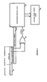
- FIG. 1A is a block diagram of the system of the present invention.
- FIG. 2 is detailed block diagram illustrating the encoding of the serial number in conjunction with the masking algorithm
- FIG. 3 is a table illustrating the functionality of an example masking algorithm
- FIG. 3A shows a table that contains the subset of those serial numbers used from the sample in FIG. 3;
- FIG. 4 is a block diagram of the application of the masking algorithm at the device registration
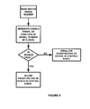
- FIGS. 5 and 6 are flowcharts of the present invention.
- FIG. 7 is a block diagram of an alternative embodiment of the invention.
- FIG. 8 is a table showing the results of the logic operations of the circuit of FIG. 7.
- a security system device 8 such as a PIR sensor, intrusion detector, smoke alarm or the like, is programmed with a unique serial number or identification number sometime during the manufacturing process.
- a serial number generation function 6 operates in conjunction with a mask generation algorithm 4 to utilize only certain serial numbers from the pool of available serial numbers; i.e. only those that meet or comply with the masking algorithm.
- the device 8 is distributed to a system installer, it is physically connected to a control panel 12 (either by wired bus 14 or a wireless connection such as an RF link) and a registration or learning process is undertaken by the control panel.
- control panel will store the serial number of the device 8 so that it can communicate with it during normal operation, as well known in the art.
- a mask reading algorithm 10 is applied to ensure that the control panel will learn only the serial numbers of the compliant devices 8 .
- FIG. 2 illustrates an exemplary embodiment of the serial number generation and masking of the present invention
- FIG. 5 is a flowchart of the methodology employed.
- serial numbers are generated sequentially by using a counter function 20 , which simply cycles through a given pool of serial numbers as required.
- a 16-bit serial number 20 is generated that can range from 0000000000000000 to 1111111111111111.
- any size serial number may be used, and a 16-bit number is shown here for illustration purposes only.
- other types of serial number generation methods may be used, such as a random or pseudo-random number generator.
- An exclusive-OR gate 24 operates on two of the available bits, which may be arbitrarily chosen. In this example, Bit 1 and Bit 4 are used, but any combination will work within the spirit and scope of this invention. Moreover, any number of inputs may be used, bearing in mind that the number of bits operated on will affect the amount of available serial numbers as will become apparent below.
- An Enable signal 25 is generated by the XOR gate 24 , which will be true (logic 1) whenever the inputs bits are different, and which will be false (logic 0) when they are the same.
- FIG. 3 is a table that shows the progression of this relationship for a sample subset of the available states of the serial number.
- the serial number 22 will be utilized by the programming logic function 26 to program the associated device with that serial is 15 number by programming it into a register 28 on the device as well known in the art.
- the Enable signal 25 is false, however, the serial number will be discarded and not programmed into the register 28 .
- the counter 20 will increment to the next sequential serial number, and the same logic process will be undertaken until the Enable signal 25 is true and the associated serial number is used to program the device.
- FIG. 3A shows a table that contains the subset of those serial numbers used from the sample in FIG. 3.
- any logic function such as an OR gate or an AND gate could be used, and of course the resulting truth table that produces Enable 25 will change accordingly.
- FIG. 4 is a block diagram of the application of the masking algorithm at the device registration stage, used to ensure that only compliant devices will be learned by the control panel.
- FIG. 6 is a flowchart of the methodology employed herein.
- a device data word 40 is output by the device during the learning/registration stage in a manner well known in the art. Included in the device data word 40 is the device serial number 22 , which had been previously programmed into the device as explained above. Bits 1 and 4 are extracted by the control panel logic and input into an exclusive-OR gate 42 , and an Enable signal 44 is generated by the output of the XOR gate.
- the Enable signal 44 is true, and the device registration logic 46 is allowed to store the serial number 22 into the control panel device table 48 , as well known the art.
- This table 48 is used by the control panel during normal operations to determine if the device that is trying to communicate with the control panel has been properly registered.
- any device that has been manufactured using the masking algorithm explained in FIG. 2 will be compliant with the registration process described here, and will be properly registered in the table 48 .
- the Enable signal 44 will be false and the device registration logic will disallow registration of the serial number 22 with the control panel device table 48 .
- user feedback could be provided (such as a beep or visual display), to signal to the installer that the process has failed.
- the masking functionality employed by this invention may also be used for another purpose; for segregating device types amongst the available serial numbers, rather than (or in addition to) filtering out serial numbers from the available pool. That is, by preparing appropriate logic functions with selected bits of the serial number, certain serial numbers can be used to program smoke alarms, others can be used to program PIRs, etc., depending on the bits chosen, the algorithm (i.e. logic) chosen, etc. This may result in sequential blocks of numbers being used for a given type of device (in a simple case), but it is not necessary to have sequential numbers.
- FIG. 7 illustrates an example of this embodiment.
- three types of devices may be programmed with serial numbers as determined by logic functions 70 , 72 and 74 . That is, smoke alarm device serial number registers 78 , microwave device serial number registers 80 , and PIR device serial number registers 82 will be programmed with a given serial number in accordance with the map shown in FIG. 8.
- SMOKE ALARM signal 71 is true due to the logic states of Bits 0 , 2 and 3 , then the serial number 22 , generated by the counter 84 , will be used to program the serial number register of a smoke alarm device 78 .
- control panel Similar logic functions will be utilized to parse the serial number of a device that is being registered, and the control panel logic will know that type of device being registered by examining the serial number bits in the same manner. This information can be used by the control panel in any manner necessary as a result of this intelligent registration process.
Abstract
Description
- This invention relates to security systems, and in particular to a system and method for using a masking algorithm as an operator on a security system device serial number to ensure that the device is compliant with the system.
- Random or sequential serial numbers have been used to set up unique identification codes for various radio controlled appliances such as garage door openers, and security systems devices such as intrusion detectors, smoke alarms, PIR sensors, etc. These identification codes are embedded in each security system device and registered or “learned” at the time of their installation by the control panel that operates the security system. Once registered with the control panel, the device will be able to communicate with the control panel as required (e.g. send and receive status messages, etc.) A device that has not been properly registered will be unable to communicate with the control panel.
- It may be desirable for a security system to register security devices manufactured at a certain location, but not from others, even if the serialization and other communications protocols would otherwise render the device registrable. As such, the present invention relates to the use of an encoding algorithm utilizing the existing serial number formats to allow or disallow registration of particular security devices, depending on the implementation of the algorithm.
- Provided is a method for configuring a security system in which a plurality of security devices are programmed with a unique identification number, and those security devices are subsequently installed in a security system.
- The security devices are programmed with unique identification numbers by first generating a series of initial serial numbers, and for each of those serial numbers, then applying a masking algorithm to the serial number. If is the masking application provides a true result, then the security device is programmed with that serial number. If the masking application provides a false result, then the serial number is discarded and not used.
- The installation of the security device includes the process of obtaining the serial number from the security device, and then applying the masking algorithm to the serial number. Registration of the security device with the control panel is allowed if the masking algorithm application provides a true result, and registration is disallowed if the masking algorithm application provides a false result.
- As a result, any security device that does not provide a true result when the masking algorithm is applied will not be registered. If a security device is provided to an installer by a manufacturer that has not utilized the masking as a sort of screening process, it may not be registrable.
- FIG. 1A is a block diagram of the system of the present invention;
- FIG. 2 is detailed block diagram illustrating the encoding of the serial number in conjunction with the masking algorithm;
- FIG. 3 is a table illustrating the functionality of an example masking algorithm;
- FIG. 3A shows a table that contains the subset of those serial numbers used from the sample in FIG. 3;
- FIG. 4 is a block diagram of the application of the masking algorithm at the device registration;
- FIGS. 5 and 6 are flowcharts of the present invention;
- FIG. 7 is a block diagram of an alternative embodiment of the invention; and
- FIG. 8 is a table showing the results of the logic operations of the circuit of FIG. 7.
- The preferred embodiment of the present invention will now be described with respect to the Figures. A
security system device 8, such as a PIR sensor, intrusion detector, smoke alarm or the like, is programmed with a unique serial number or identification number sometime during the manufacturing process. A serialnumber generation function 6 operates in conjunction with amask generation algorithm 4 to utilize only certain serial numbers from the pool of available serial numbers; i.e. only those that meet or comply with the masking algorithm. After thedevice 8 is distributed to a system installer, it is physically connected to a control panel 12 (either bywired bus 14 or a wireless connection such as an RF link) and a registration or learning process is undertaken by the control panel. During this process, the control panel will store the serial number of thedevice 8 so that it can communicate with it during normal operation, as well known in the art. In accordance with this invention, amask reading algorithm 10 is applied to ensure that the control panel will learn only the serial numbers of thecompliant devices 8. - FIG. 2 illustrates an exemplary embodiment of the serial number generation and masking of the present invention, and FIG. 5 is a flowchart of the methodology employed. In this embodiment, serial numbers are generated sequentially by using a
counter function 20, which simply cycles through a given pool of serial numbers as required. A 16-bit serial number 20 is generated that can range from 0000000000000000 to 1111111111111111. Of course, any size serial number may be used, and a 16-bit number is shown here for illustration purposes only. In addition, other types of serial number generation methods may be used, such as a random or pseudo-random number generator. - An exclusive-OR
gate 24 operates on two of the available bits, which may be arbitrarily chosen. In this example,Bit 1 andBit 4 are used, but any combination will work within the spirit and scope of this invention. Moreover, any number of inputs may be used, bearing in mind that the number of bits operated on will affect the amount of available serial numbers as will become apparent below. - An
Enable signal 25 is generated by theXOR gate 24, which will be true (logic 1) whenever the inputs bits are different, and which will be false (logic 0) when they are the same. FIG. 3 is a table that shows the progression of this relationship for a sample subset of the available states of the serial number. Whenever theEnable signal 25 is true, theserial number 22 will be utilized by theprogramming logic function 26 to program the associated device with that serial is 15 number by programming it into aregister 28 on the device as well known in the art. Whenever theEnable signal 25 is false, however, the serial number will be discarded and not programmed into theregister 28. Thecounter 20 will increment to the next sequential serial number, and the same logic process will be undertaken until theEnable signal 25 is true and the associated serial number is used to program the device. - As a result, only those serial numbers where
Bit 1 andBit 4 have different values will be used; those where both bits are logic one or both bits arelogic 0 will not be used. FIG. 3A shows a table that contains the subset of those serial numbers used from the sample in FIG. 3. As a variation, any logic function such as an OR gate or an AND gate could be used, and of course the resulting truth table that produces Enable 25 will change accordingly. - FIG. 4 is a block diagram of the application of the masking algorithm at the device registration stage, used to ensure that only compliant devices will be learned by the control panel. FIG. 6 is a flowchart of the methodology employed herein. A
device data word 40 is output by the device during the learning/registration stage in a manner well known in the art. Included in thedevice data word 40 is thedevice serial number 22, which had been previously programmed into the device as explained above.Bits OR gate 42, and anEnable signal 44 is generated by the output of the XOR gate. WhenBits Enable signal 44 is true, and thedevice registration logic 46 is allowed to store theserial number 22 into the control panel device table 48, as well known the art. This table 48 is used by the control panel during normal operations to determine if the device that is trying to communicate with the control panel has been properly registered. Of course, any device that has been manufactured using the masking algorithm explained in FIG. 2 will be compliant with the registration process described here, and will be properly registered in the table 48. - If, however, a non-compliant device (i.e. one with
bits logic 0 or both logic 1) tries to register with the control panel, then theEnable signal 44 will be false and the device registration logic will disallow registration of theserial number 22 with the control panel device table 48. Optionally, user feedback could be provided (such as a beep or visual display), to signal to the installer that the process has failed. - The masking functionality employed by this invention may also be used for another purpose; for segregating device types amongst the available serial numbers, rather than (or in addition to) filtering out serial numbers from the available pool. That is, by preparing appropriate logic functions with selected bits of the serial number, certain serial numbers can be used to program smoke alarms, others can be used to program PIRs, etc., depending on the bits chosen, the algorithm (i.e. logic) chosen, etc. This may result in sequential blocks of numbers being used for a given type of device (in a simple case), but it is not necessary to have sequential numbers.
- FIG. 7 illustrates an example of this embodiment. There, three types of devices may be programmed with serial numbers as determined by
logic functions SMOKE ALARM signal 71 is true due to the logic states ofBits serial number 22, generated by thecounter 84, will be used to program the serial number register of a smoke alarm device 78. When MICROWAVE signal 73 is true due to the logic states ofBits serial number 22 will be used to program the serial number register of amicrowave device 80. When PIR signal 82 is true due to the logic states ofBits serial number 22 will be used to program the serial number register of aPIR device 82. Other logic functions and bit selections may of course be made in the spirit and scope of this invention. - At the control panel, similar logic functions will be utilized to parse the serial number of a device that is being registered, and the control panel logic will know that type of device being registered by examining the serial number bits in the same manner. This information can be used by the control panel in any manner necessary as a result of this intelligent registration process.
Claims (18)
Priority Applications (3)
| Application Number | Priority Date | Filing Date | Title |
|---|---|---|---|
| US10/115,420 US7120795B2 (en) | 2002-04-03 | 2002-04-03 | Security system with serial number coding and methods therefor |
| AU2003230737A AU2003230737A1 (en) | 2002-04-03 | 2003-03-26 | Security system with serial number coding and methods therefor |
| PCT/US2003/009236 WO2003085880A1 (en) | 2002-04-03 | 2003-03-26 | Security system with serial number coding and methods therefor |
Applications Claiming Priority (1)
| Application Number | Priority Date | Filing Date | Title |
|---|---|---|---|
| US10/115,420 US7120795B2 (en) | 2002-04-03 | 2002-04-03 | Security system with serial number coding and methods therefor |
Publications (2)
| Publication Number | Publication Date |
|---|---|
| US20030191959A1 true US20030191959A1 (en) | 2003-10-09 |
| US7120795B2 US7120795B2 (en) | 2006-10-10 |
Family
ID=28673772
Family Applications (1)
| Application Number | Title | Priority Date | Filing Date |
|---|---|---|---|
| US10/115,420 Active 2024-07-14 US7120795B2 (en) | 2002-04-03 | 2002-04-03 | Security system with serial number coding and methods therefor |
Country Status (3)
| Country | Link |
|---|---|
| US (1) | US7120795B2 (en) |
| AU (1) | AU2003230737A1 (en) |
| WO (1) | WO2003085880A1 (en) |
Cited By (4)
| Publication number | Priority date | Publication date | Assignee | Title |
|---|---|---|---|---|
| US20110063093A1 (en) * | 2009-07-10 | 2011-03-17 | Certicom Corp. | System and method for performing serialization of devices |
| US20120068686A1 (en) * | 2008-09-03 | 2012-03-22 | Lutron Electronics Co., Inc. | Radio-frequency lighting control system with occupancy sensing |
| US10462882B2 (en) | 2008-09-03 | 2019-10-29 | Lutron Technology Company Llc | Control system with occupancy sensing |
| CN111199395A (en) * | 2018-11-20 | 2020-05-26 | 千寻位置网络有限公司 | Control method and device for equipment charging and charging system |
Families Citing this family (9)
| Publication number | Priority date | Publication date | Assignee | Title |
|---|---|---|---|---|
| US8269627B2 (en) | 2007-11-30 | 2012-09-18 | Andersen Corporation | Status monitoring system for a fenestration unit |
| US8456278B1 (en) | 2010-03-24 | 2013-06-04 | Resolution Products, Inc. | Communicating within a wireless security system |
| CA2843272C (en) | 2011-07-29 | 2020-06-02 | Adt Us Holdings, Inc. | Security system and method |
| US8970373B2 (en) | 2012-04-09 | 2015-03-03 | Honeywell International Inc. | Large gap door/window, high security, intrusion detectors using magnetometers |
| EP2898489B1 (en) | 2012-09-18 | 2019-10-09 | Vootner Goushe LLC | Sensor system for protection of artworks and other valuable objects |
| US10317247B1 (en) | 2015-01-05 | 2019-06-11 | Andersen Corporation | Fenestration unit monitoring apparatus with tethers and methods |
| US10228266B1 (en) | 2015-01-05 | 2019-03-12 | Andersen Corporation | Fenestration unit monitoring devices and methods |
| US10234307B1 (en) | 2015-01-05 | 2019-03-19 | Andersen Corporation | Slot-based fenestration unit monitoring apparatus and methods |
| WO2017172993A1 (en) | 2016-03-29 | 2017-10-05 | Resolution Products, Inc. | Universal protocol translator |
Citations (6)
| Publication number | Priority date | Publication date | Assignee | Title |
|---|---|---|---|---|
| US5970148A (en) * | 1997-05-02 | 1999-10-19 | Texas Instruments Deutschland, Gmbh | Low cost encryption transponder |
| US6400265B1 (en) * | 2001-04-24 | 2002-06-04 | Microstrategy, Inc. | System and method for monitoring security systems by using video images |
| US20020091805A1 (en) * | 2000-01-14 | 2002-07-11 | Microsoft Corporation | Method and system for dynamically purposing a computing device |
| US20030023874A1 (en) * | 2001-07-16 | 2003-01-30 | Rudy Prokupets | System for integrating security and access for facilities and information systems |
| US20030063742A1 (en) * | 2001-09-28 | 2003-04-03 | Neufeld E. David | Method and apparatus for generating a strong random number for use in a security subsystem for a processor-based device |
| US6552647B1 (en) * | 1999-07-01 | 2003-04-22 | Ricky H. Thiessen | Building environment monitor and control system |
-
2002
- 2002-04-03 US US10/115,420 patent/US7120795B2/en active Active
-
2003
- 2003-03-26 AU AU2003230737A patent/AU2003230737A1/en not_active Abandoned
- 2003-03-26 WO PCT/US2003/009236 patent/WO2003085880A1/en not_active Application Discontinuation
Patent Citations (6)
| Publication number | Priority date | Publication date | Assignee | Title |
|---|---|---|---|---|
| US5970148A (en) * | 1997-05-02 | 1999-10-19 | Texas Instruments Deutschland, Gmbh | Low cost encryption transponder |
| US6552647B1 (en) * | 1999-07-01 | 2003-04-22 | Ricky H. Thiessen | Building environment monitor and control system |
| US20020091805A1 (en) * | 2000-01-14 | 2002-07-11 | Microsoft Corporation | Method and system for dynamically purposing a computing device |
| US6400265B1 (en) * | 2001-04-24 | 2002-06-04 | Microstrategy, Inc. | System and method for monitoring security systems by using video images |
| US20030023874A1 (en) * | 2001-07-16 | 2003-01-30 | Rudy Prokupets | System for integrating security and access for facilities and information systems |
| US20030063742A1 (en) * | 2001-09-28 | 2003-04-03 | Neufeld E. David | Method and apparatus for generating a strong random number for use in a security subsystem for a processor-based device |
Cited By (9)
| Publication number | Priority date | Publication date | Assignee | Title |
|---|---|---|---|---|
| US20120068686A1 (en) * | 2008-09-03 | 2012-03-22 | Lutron Electronics Co., Inc. | Radio-frequency lighting control system with occupancy sensing |
| US9277629B2 (en) * | 2008-09-03 | 2016-03-01 | Lutron Electronics Co., Inc. | Radio-frequency lighting control system with occupancy sensing |
| US10462882B2 (en) | 2008-09-03 | 2019-10-29 | Lutron Technology Company Llc | Control system with occupancy sensing |
| US11129262B2 (en) | 2008-09-03 | 2021-09-21 | Lutron Technology Company Llc | Control system with occupancy sensing |
| US11743999B2 (en) | 2008-09-03 | 2023-08-29 | Lutron Technology Company Llc | Control system with occupancy sensing |
| US20110063093A1 (en) * | 2009-07-10 | 2011-03-17 | Certicom Corp. | System and method for performing serialization of devices |
| US9208459B2 (en) * | 2009-07-10 | 2015-12-08 | Certicom Corp. | System and method for performing serialization of devices |
| US10102500B2 (en) * | 2009-07-10 | 2018-10-16 | Certicom Corp. | System and method for performing serialization of devices |
| CN111199395A (en) * | 2018-11-20 | 2020-05-26 | 千寻位置网络有限公司 | Control method and device for equipment charging and charging system |
Also Published As
| Publication number | Publication date |
|---|---|
| WO2003085880A1 (en) | 2003-10-16 |
| AU2003230737A1 (en) | 2003-10-20 |
| US7120795B2 (en) | 2006-10-10 |
Similar Documents
| Publication | Publication Date | Title |
|---|---|---|
| US7120795B2 (en) | Security system with serial number coding and methods therefor | |
| US10425509B2 (en) | Communicating within a wireless security system | |
| CN109167796B (en) | Deep packet inspection platform based on industrial SCADA system | |
| JP7288162B2 (en) | Intrusion anomaly monitoring in vehicle environment | |
| US6167137A (en) | Secure communications in a wireless system | |
| US5339073A (en) | Access control equipment and method for using the same | |
| CN1306355C (en) | Integrated circuit protection and method therefor | |
| US10516765B2 (en) | Universal protocol translator | |
| US6987450B2 (en) | Method and apparatus for determining message response type in a security system | |
| US6690276B1 (en) | Method and apparatus for monitoring message acknowledgements in a security system | |
| US4926162A (en) | High security communication line monitor | |
| KR102199054B1 (en) | Apparatus for serial port based cyber security vulnerability assessment and method for the same | |
| US6366215B1 (en) | Communications systems and methods | |
| CN113612786B (en) | Intrusion detection system and method for vehicle bus | |
| CN101647234B (en) | The method and system of the cyclical transmission process waiting for transmission data for safety | |
| CN111447166B (en) | Vehicle attack detection method and device | |
| CN105095753A (en) | Broadcast safe detection method and device | |
| Francia et al. | Applied machine learning to vehicle security | |
| CA1073127A (en) | Clock gated digital data encoding circuit | |
| Boumiza et al. | An efficient hidden Markov model for anomaly detection in can bus networks | |
| US20040075551A1 (en) | Method and apparatus for filtering non-essential messages in a disarmed security system | |
| KR20060057916A (en) | Method and apparatus for generating network packet which includes the attack packet generation functionality for information security system testing | |
| KR102469399B1 (en) | Attack detection system of can network, attack detection method of can network and computer program stored in a recording medium to execute the method | |
| US20040186879A1 (en) | Apparatus and method for setting communication packet | |
| US6696940B2 (en) | System and method for loop diagnostics in a security system |
Legal Events
| Date | Code | Title | Description |
|---|---|---|---|
| AS | Assignment |
Owner name: PITTWAY CORP., ILLINOIS Free format text: ASSIGNMENT OF ASSIGNORS INTEREST;ASSIGNORS:RAPHAEL, MARTIN;ADDY, KENNETH L.;REEL/FRAME:012763/0163 Effective date: 20020401 |
|
| AS | Assignment |
Owner name: HONEYWELL INTERNATIONAL INC., NEW JERSEY Free format text: MERGER;ASSIGNOR:PITTWAY CORPORATION;REEL/FRAME:014223/0953 Effective date: 20030327 |
|
| STCF | Information on status: patent grant |
Free format text: PATENTED CASE |
|
| FPAY | Fee payment |
Year of fee payment: 4 |
|
| FPAY | Fee payment |
Year of fee payment: 8 |
|
| MAFP | Maintenance fee payment |
Free format text: PAYMENT OF MAINTENANCE FEE, 12TH YEAR, LARGE ENTITY (ORIGINAL EVENT CODE: M1553) Year of fee payment: 12 |
|
| AS | Assignment |
Owner name: JPMORGAN CHASE BANK, N.A., AS ADMINISTRATIVE AGENT, NEW YORK Free format text: SECURITY INTEREST;ASSIGNOR:ADEMCO INC.;REEL/FRAME:047337/0577 Effective date: 20181025 Owner name: JPMORGAN CHASE BANK, N.A., AS ADMINISTRATIVE AGENT Free format text: SECURITY INTEREST;ASSIGNOR:ADEMCO INC.;REEL/FRAME:047337/0577 Effective date: 20181025 |
|
| AS | Assignment |
Owner name: ADEMCO INC., MINNESOTA Free format text: ASSIGNMENT OF ASSIGNORS INTEREST;ASSIGNOR:HONEYWELL INTERNATIONAL INC.;REEL/FRAME:047909/0425 Effective date: 20181029 |
|
| AS | Assignment |
Owner name: ADEMCO INC., MINNESOTA Free format text: CORRECTIVE ASSIGNMENT TO CORRECT THE PREVIOUS RECORDING BY NULLIFICATION. THE INCORRECTLY RECORDED PATENT NUMBERS 8545483, 8612538 AND 6402691 PREVIOUSLY RECORDED AT REEL: 047909 FRAME: 0425. ASSIGNOR(S) HEREBY CONFIRMS THE ASSIGNMENT;ASSIGNOR:HONEYWELL INTERNATIONAL INC.;REEL/FRAME:050431/0053 Effective date: 20190215 |