EP3241481A1 - Dual path endoscope - Google Patents
Dual path endoscope Download PDFInfo
- Publication number
- EP3241481A1 EP3241481A1 EP17000751.2A EP17000751A EP3241481A1 EP 3241481 A1 EP3241481 A1 EP 3241481A1 EP 17000751 A EP17000751 A EP 17000751A EP 3241481 A1 EP3241481 A1 EP 3241481A1
- Authority
- EP
- European Patent Office
- Prior art keywords
- light
- image
- light source
- endoscope
- optical
- Prior art date
- Legal status (The legal status is an assumption and is not a legal conclusion. Google has not performed a legal analysis and makes no representation as to the accuracy of the status listed.)
- Granted
Links
- 230000009977 dual effect Effects 0.000 title claims description 35
- 238000003384 imaging method Methods 0.000 claims abstract description 100
- 210000001747 pupil Anatomy 0.000 claims abstract description 38
- 238000000034 method Methods 0.000 claims abstract description 36
- 230000035945 sensitivity Effects 0.000 claims abstract description 9
- 230000003287 optical effect Effects 0.000 claims description 90
- 239000013307 optical fiber Substances 0.000 claims description 13
- 230000001747 exhibiting effect Effects 0.000 claims description 11
- 230000010287 polarization Effects 0.000 claims description 4
- 230000005284 excitation Effects 0.000 description 4
- 238000002073 fluorescence micrograph Methods 0.000 description 3
- 229910052724 xenon Inorganic materials 0.000 description 3
- FHNFHKCVQCLJFQ-UHFFFAOYSA-N xenon atom Chemical compound [Xe] FHNFHKCVQCLJFQ-UHFFFAOYSA-N 0.000 description 3
- 238000010420 art technique Methods 0.000 description 2
- 230000017531 blood circulation Effects 0.000 description 2
- 239000003795 chemical substances by application Substances 0.000 description 2
- 239000004065 semiconductor Substances 0.000 description 2
- 238000001228 spectrum Methods 0.000 description 2
- 230000002238 attenuated effect Effects 0.000 description 1
- 230000003190 augmentative effect Effects 0.000 description 1
- 239000003086 colorant Substances 0.000 description 1
- 230000000295 complement effect Effects 0.000 description 1
- 239000000835 fiber Substances 0.000 description 1
- 238000001914 filtration Methods 0.000 description 1
- 238000005286 illumination Methods 0.000 description 1
- 229910044991 metal oxide Inorganic materials 0.000 description 1
- 150000004706 metal oxides Chemical class 0.000 description 1
- 230000010412 perfusion Effects 0.000 description 1
- 230000005855 radiation Effects 0.000 description 1
- 238000001356 surgical procedure Methods 0.000 description 1
- 238000012800 visualization Methods 0.000 description 1
Images


Classifications
-
- A—HUMAN NECESSITIES
- A61—MEDICAL OR VETERINARY SCIENCE; HYGIENE
- A61B—DIAGNOSIS; SURGERY; IDENTIFICATION
- A61B1/00—Instruments for performing medical examinations of the interior of cavities or tubes of the body by visual or photographical inspection, e.g. endoscopes; Illuminating arrangements therefor
- A61B1/00002—Operational features of endoscopes
- A61B1/00004—Operational features of endoscopes characterised by electronic signal processing
- A61B1/00009—Operational features of endoscopes characterised by electronic signal processing of image signals during a use of endoscope
-
- H—ELECTRICITY
- H04—ELECTRIC COMMUNICATION TECHNIQUE
- H04N—PICTORIAL COMMUNICATION, e.g. TELEVISION
- H04N23/00—Cameras or camera modules comprising electronic image sensors; Control thereof
- H04N23/56—Cameras or camera modules comprising electronic image sensors; Control thereof provided with illuminating means
-
- A—HUMAN NECESSITIES
- A61—MEDICAL OR VETERINARY SCIENCE; HYGIENE
- A61B—DIAGNOSIS; SURGERY; IDENTIFICATION
- A61B1/00—Instruments for performing medical examinations of the interior of cavities or tubes of the body by visual or photographical inspection, e.g. endoscopes; Illuminating arrangements therefor
- A61B1/00002—Operational features of endoscopes
- A61B1/00043—Operational features of endoscopes provided with output arrangements
- A61B1/00045—Display arrangement
- A61B1/0005—Display arrangement combining images e.g. side-by-side, superimposed or tiled
-
- A—HUMAN NECESSITIES
- A61—MEDICAL OR VETERINARY SCIENCE; HYGIENE
- A61B—DIAGNOSIS; SURGERY; IDENTIFICATION
- A61B1/00—Instruments for performing medical examinations of the interior of cavities or tubes of the body by visual or photographical inspection, e.g. endoscopes; Illuminating arrangements therefor
- A61B1/00163—Optical arrangements
- A61B1/00193—Optical arrangements adapted for stereoscopic vision
-
- A—HUMAN NECESSITIES
- A61—MEDICAL OR VETERINARY SCIENCE; HYGIENE
- A61B—DIAGNOSIS; SURGERY; IDENTIFICATION
- A61B1/00—Instruments for performing medical examinations of the interior of cavities or tubes of the body by visual or photographical inspection, e.g. endoscopes; Illuminating arrangements therefor
- A61B1/00163—Optical arrangements
- A61B1/00194—Optical arrangements adapted for three-dimensional imaging
-
- A—HUMAN NECESSITIES
- A61—MEDICAL OR VETERINARY SCIENCE; HYGIENE
- A61B—DIAGNOSIS; SURGERY; IDENTIFICATION
- A61B1/00—Instruments for performing medical examinations of the interior of cavities or tubes of the body by visual or photographical inspection, e.g. endoscopes; Illuminating arrangements therefor
- A61B1/04—Instruments for performing medical examinations of the interior of cavities or tubes of the body by visual or photographical inspection, e.g. endoscopes; Illuminating arrangements therefor combined with photographic or television appliances
- A61B1/043—Instruments for performing medical examinations of the interior of cavities or tubes of the body by visual or photographical inspection, e.g. endoscopes; Illuminating arrangements therefor combined with photographic or television appliances for fluorescence imaging
-
- A—HUMAN NECESSITIES
- A61—MEDICAL OR VETERINARY SCIENCE; HYGIENE
- A61B—DIAGNOSIS; SURGERY; IDENTIFICATION
- A61B1/00—Instruments for performing medical examinations of the interior of cavities or tubes of the body by visual or photographical inspection, e.g. endoscopes; Illuminating arrangements therefor
- A61B1/06—Instruments for performing medical examinations of the interior of cavities or tubes of the body by visual or photographical inspection, e.g. endoscopes; Illuminating arrangements therefor with illuminating arrangements
- A61B1/0638—Instruments for performing medical examinations of the interior of cavities or tubes of the body by visual or photographical inspection, e.g. endoscopes; Illuminating arrangements therefor with illuminating arrangements providing two or more wavelengths
-
- A—HUMAN NECESSITIES
- A61—MEDICAL OR VETERINARY SCIENCE; HYGIENE
- A61B—DIAGNOSIS; SURGERY; IDENTIFICATION
- A61B1/00—Instruments for performing medical examinations of the interior of cavities or tubes of the body by visual or photographical inspection, e.g. endoscopes; Illuminating arrangements therefor
- A61B1/06—Instruments for performing medical examinations of the interior of cavities or tubes of the body by visual or photographical inspection, e.g. endoscopes; Illuminating arrangements therefor with illuminating arrangements
- A61B1/0646—Instruments for performing medical examinations of the interior of cavities or tubes of the body by visual or photographical inspection, e.g. endoscopes; Illuminating arrangements therefor with illuminating arrangements with illumination filters
-
- A—HUMAN NECESSITIES
- A61—MEDICAL OR VETERINARY SCIENCE; HYGIENE
- A61B—DIAGNOSIS; SURGERY; IDENTIFICATION
- A61B1/00—Instruments for performing medical examinations of the interior of cavities or tubes of the body by visual or photographical inspection, e.g. endoscopes; Illuminating arrangements therefor
- A61B1/06—Instruments for performing medical examinations of the interior of cavities or tubes of the body by visual or photographical inspection, e.g. endoscopes; Illuminating arrangements therefor with illuminating arrangements
- A61B1/07—Instruments for performing medical examinations of the interior of cavities or tubes of the body by visual or photographical inspection, e.g. endoscopes; Illuminating arrangements therefor with illuminating arrangements using light-conductive means, e.g. optical fibres
-
- G—PHYSICS
- G02—OPTICS
- G02B—OPTICAL ELEMENTS, SYSTEMS OR APPARATUS
- G02B23/00—Telescopes, e.g. binoculars; Periscopes; Instruments for viewing the inside of hollow bodies; Viewfinders; Optical aiming or sighting devices
- G02B23/24—Instruments or systems for viewing the inside of hollow bodies, e.g. fibrescopes
- G02B23/2407—Optical details
- G02B23/2415—Stereoscopic endoscopes
-
- G—PHYSICS
- G02—OPTICS
- G02B—OPTICAL ELEMENTS, SYSTEMS OR APPARATUS
- G02B23/00—Telescopes, e.g. binoculars; Periscopes; Instruments for viewing the inside of hollow bodies; Viewfinders; Optical aiming or sighting devices
- G02B23/24—Instruments or systems for viewing the inside of hollow bodies, e.g. fibrescopes
- G02B23/2407—Optical details
- G02B23/2461—Illumination
-
- G—PHYSICS
- G02—OPTICS
- G02B—OPTICAL ELEMENTS, SYSTEMS OR APPARATUS
- G02B23/00—Telescopes, e.g. binoculars; Periscopes; Instruments for viewing the inside of hollow bodies; Viewfinders; Optical aiming or sighting devices
- G02B23/24—Instruments or systems for viewing the inside of hollow bodies, e.g. fibrescopes
- G02B23/2476—Non-optical details, e.g. housings, mountings, supports
- G02B23/2484—Arrangements in relation to a camera or imaging device
-
- G—PHYSICS
- G02—OPTICS
- G02B—OPTICAL ELEMENTS, SYSTEMS OR APPARATUS
- G02B5/00—Optical elements other than lenses
- G02B5/20—Filters
- G02B5/208—Filters for use with infrared or ultraviolet radiation, e.g. for separating visible light from infrared and/or ultraviolet radiation
-
- H—ELECTRICITY
- H04—ELECTRIC COMMUNICATION TECHNIQUE
- H04N—PICTORIAL COMMUNICATION, e.g. TELEVISION
- H04N23/00—Cameras or camera modules comprising electronic image sensors; Control thereof
- H04N23/10—Cameras or camera modules comprising electronic image sensors; Control thereof for generating image signals from different wavelengths
- H04N23/11—Cameras or camera modules comprising electronic image sensors; Control thereof for generating image signals from different wavelengths for generating image signals from visible and infrared light wavelengths
-
- H—ELECTRICITY
- H04—ELECTRIC COMMUNICATION TECHNIQUE
- H04N—PICTORIAL COMMUNICATION, e.g. TELEVISION
- H04N23/00—Cameras or camera modules comprising electronic image sensors; Control thereof
- H04N23/10—Cameras or camera modules comprising electronic image sensors; Control thereof for generating image signals from different wavelengths
- H04N23/13—Cameras or camera modules comprising electronic image sensors; Control thereof for generating image signals from different wavelengths with multiple sensors
- H04N23/16—Optical arrangements associated therewith, e.g. for beam-splitting or for colour correction
-
- H—ELECTRICITY
- H04—ELECTRIC COMMUNICATION TECHNIQUE
- H04N—PICTORIAL COMMUNICATION, e.g. TELEVISION
- H04N23/00—Cameras or camera modules comprising electronic image sensors; Control thereof
- H04N23/50—Constructional details
- H04N23/555—Constructional details for picking-up images in sites, inaccessible due to their dimensions or hazardous conditions, e.g. endoscopes or borescopes
-
- H—ELECTRICITY
- H04—ELECTRIC COMMUNICATION TECHNIQUE
- H04N—PICTORIAL COMMUNICATION, e.g. TELEVISION
- H04N23/00—Cameras or camera modules comprising electronic image sensors; Control thereof
- H04N23/60—Control of cameras or camera modules
- H04N23/63—Control of cameras or camera modules by using electronic viewfinders
-
- A—HUMAN NECESSITIES
- A61—MEDICAL OR VETERINARY SCIENCE; HYGIENE
- A61B—DIAGNOSIS; SURGERY; IDENTIFICATION
- A61B1/00—Instruments for performing medical examinations of the interior of cavities or tubes of the body by visual or photographical inspection, e.g. endoscopes; Illuminating arrangements therefor
- A61B1/00163—Optical arrangements
- A61B1/00165—Optical arrangements with light-conductive means, e.g. fibre optics
- A61B1/00167—Details of optical fibre bundles, e.g. shape or fibre distribution
-
- A—HUMAN NECESSITIES
- A61—MEDICAL OR VETERINARY SCIENCE; HYGIENE
- A61B—DIAGNOSIS; SURGERY; IDENTIFICATION
- A61B1/00—Instruments for performing medical examinations of the interior of cavities or tubes of the body by visual or photographical inspection, e.g. endoscopes; Illuminating arrangements therefor
- A61B1/00163—Optical arrangements
- A61B1/00186—Optical arrangements with imaging filters
-
- H—ELECTRICITY
- H04—ELECTRIC COMMUNICATION TECHNIQUE
- H04N—PICTORIAL COMMUNICATION, e.g. TELEVISION
- H04N9/00—Details of colour television systems
- H04N9/64—Circuits for processing colour signals
- H04N9/646—Circuits for processing colour signals for image enhancement, e.g. vertical detail restoration, cross-colour elimination, contour correction, chrominance trapping filters
Definitions
- the disclosed technique relates to endoscopes in general, and to a dual path endoscope system with non-zero disparity between the two paths and methods therefor in particular.
- a fluorescent endoscope is an imaging system for imaging blood flow, by imaging fluorescence radiation emitted by a fluorescence agent (e.g., a dye) illuminated by light generated by a fluorescent light source.
- a fluorescence agent e.g., a dye
- Such an endoscope may be employed, for example, during surgery for visualizing the blood flow, and for evaluating tissue perfusion.
- an additional visible light image of the observed area may be employed to provide anatomical reference to the fluorescent image.
- the fluorescence image and white light image are acquired through the same channel of an endoscope (either in 3D or 2D imaging modes).
- an endoscope either in 3D or 2D imaging modes
- two dissimilar imaging modalities are transmitted over the same channel of an endoscope.
- the registration between the two images is simplified, the image acquisition is either interspersed in time (i.e., only white light image or fluorescent image are acquired at a time) or the white illumination is substantially attenuated to allow the relatively weaker fluorescence signal to be brighter than the background white light image.
- U.S. Patent 8,810,631 to Scott et al entitled "Augmented stereoscopic visualization for a surgical robot using a captured visible image combined with a fluorescence image and a captured visible image” directs to an endoscope system which includes image capture system and a combination light source.
- the combination light source produces white light and at least one fluorescence excitation light.
- the imaging system captures light returned from tissue of a patient.
- the imaging system includes 2 Charge Coupled Device (CCD) sensors.
- One CCD sensor captures an image of the white light only and the other CCD sensor captures an image of both white and fluorescent light.
- a processor processes the acquired images to generate a 3D stereoscopic image of both white light and fluorescent light.
- the system includes a multi-function light source, an endoscope, a dual channel imager and a processor coupled with the dual channel imager.
- the multi-function light source produces a first light and a second light and directs the first light and the second light toward an object.
- the first light exhibits first light characteristics.
- the second light exhibits second light characteristics different from the first light characteristics.
- the endoscope includes two light paths, the disparity between the two light paths is larger than zero.
- Each light path at least includes a respective pupil and a respective light separator coupled with the pupil for transmitting there through a respective one of the first light and the second light, thereby associating the first light and the second light with a respective light path.
- the dual channel imager at least includes two imaging sensors. Each imaging sensor is associated with a respective one of the light paths. Each imaging sensor is optically coupled with the light separator associated with the respective light path. Each imaging sensor exhibits sensitivity to the characteristics of the respective one of the first light and the second light. A first one of the imaging sensors acquires a first image of the first light reflected of the object and a second one of the imaging sensors acquires a second image of the second light reflected of the object. The processor processes the acquired images.
- Such a dual path endoscope includes a two-channel imager, which includes two image sensors. One sensor is sensitive to a first light exhibiting respective first light characteristics and the other sensor is sensitive to a second light exhibiting respective second light characteristics different from the first light characteristics.
- the first light is visible light and the second light is Infrared (IR) light.
- a dual path endoscope system is a fluorescent endoscope in which one path is a fluorescence path which employs a fluorescent light (e.g., a laser which excites a fluorescence agent such as a dye) for acquiring a fluorescent image.
- the other path is a visible light path for acquiring a visible light image.
- the two images may be displayed separately.
- the non-zero disparity may be accounted for by employing image processing to generate a 2D image or enables a combined 3D image from the two images.
- the non-zero disparity physically enables to employ two separate optical paths, thus allowing the visible light path to be independent of the fluorescence light path.
- the dual channel imager may be located in either distal end of the dual path endoscope or the proximal end of the dual path endoscope.
- An image sensor may be a single chip sensor containing an integrated color filter or a multi-chip sensor with prisms to separate colors according to wavelength.
- Figure 1A is a schematic illustration of a dual path endoscope system, generally referenced 100, constructed and operative in accordance with an embodiment of the disclosed technique.
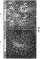
- Figure 1B is a schematic illustration of two images, 150 and 152 acquired with a system such as endoscope system 100.
- Figure 1C is a schematic illustration of a combined image 154 acquired with a system such as endoscope system 100.
- endoscope system 100 includes a dual path imager 102, a multi-function light source 104, a processor 103, a display 105 and an endoscope 107.
- Endoscope 107 includes an optical terminal 106, optical fibers 108 1 , 108 2 and 108 3 and two optical channels, first optical channel 110 1 and second optical channel 110 2 .
- Dual channel imager 102 is located at the proximal end of endoscope 107 and includes a first image sensor 112, a second image sensor 114, first imaging optics 116, second imaging optics 118, first light separator 120 and second light separator 122.
- Multi-function light source 104 includes a first light source 124 and a second light source 126, first light source optics 128, second light source optics 130 an optical combiner 132.
- Multi-function light source 104 optionally includes a short pass filter 134.
- Processor 103 is coupled with display 105 and with dual channel imager 102.
- First imaging optics 116 is optically coupled with first imaging sensor 112 and with first light separator 120 and located therebetween.
- Second imaging optics 118 is optically coupled with first imaging sensor 114 and with first light separator 122 and located therebetween.
- First light separator 120 is optically coupled with first optical channel 110 1 and second light separator 122 is optically coupled with second optical channel 110 2 .
- Entry pupil 138 1 , first optical channel 110 1 , first light separator 120 define a first light path.
- Entry pupil 138 1 , first optical channel 110 1 , first light separator 120, first imaging optics 116 and first imaging sensor 112 define a first image acquisition channel associated with the light generated by first light source 124.
- Entry pupil 138 2 , Second optical channel 110 2 , second light separator 122 define a second light path.
- Entry pupil 138 2 , Second optical channel 110 2 , second light separator 122, second imaging optics 118 and second imaging sensor 114 define a second image acquisition channel associated with the light generated by second light source 126.
- the disparity 'D' between entry pupils 138 1 and 138 2 and thus between the two image acquisition channels is larger than zero (i.e., D>0).
- the term 'image acquisition channel' and 'image acquisition path' are used herein interchangeably.
- First light source optics 128 is optically coupled with first light source 124 and optical combiner 132 and located therebetween.
- Second light source optics 130 is optically coupled with second light source 126 and optical combiner 132 located therebetween.
- Optical combiner 132 is optically coupled with optical terminal 106.
- Optical terminal 106 is coupled with optical fibers 108 1 , 108 2 and 108 3 .
- first light source 124 exhibits different distinguishable light characteristics (e.g., different wavelength, different polarization or different phase) from the light characteristics generated by second light source 126.
- the term 'distinguishable light characteristics' refers herein to characteristics by which the two lights may be distinguished therebetween, for example, with the aid of optical elements (e.g., filters) or with the aid of processing.
- First light source 124 is typically a white light source such as a Xenon light.
- short pass filter 134 is included in multi-function light source 104, then short pass filter 134 attenuates light exhibiting wavelengths above a cutoff wavelength (e.g., above 700 nanometers).
- Second light source 126 is typically a fluorescence excitation light generated for example by a laser diode (e.g., at a wavelength of 805 nanometers).
- light source 104 is depicted as including two light sources. However, in general, light source 104 may include more than two sources exhibiting distinguishable characteristics therebetween.
- First imaging sensor 112 exhibits sensitivity in the wavelengths range of the light generated by first light source 124 and second imaging sensor exhibits sensitivity in the wavelengths range of the light generated by second light source.
- First imaging sensor 112 and second imaging sensors 124 are, for example CCD sensors or Complementary Metal Oxide Semiconductor (CMOS) sensor.
- First optical channel 110 1 and second optical channel 110 2 are position along endoscope 107 and may be constructed from an array of optical elements such lenses, rod lenses mirrors and the like.
- First light source 124 projects the light generated thereby, indicated by a dotted line in Figure 1A , toward first light optics 128.
- First light optics 128 focuses this light onto optical combiner 132.
- Second light source 126 projects the light generated thereby, indicated by a dashed line in Figure 1A , toward second light optics 130.
- Second light optics 130 focuses this light onto optical combiner 132.
- Optical combiner 132 reflects the first light (i.e., generated by first light source 124) and transmits the second light (i.e., generated by second light source 126) to generate a combined light.
- the combined light is then transmitted into optical fibers 108 1 , 108 2 and 108 3 by optical terminal 106.
- Optical fibers 108 1 , 108 2 and 108 3 transmit combined light through endoscope 107, which transmit the combined light onto object 136.
- light source 104 may direct the light generated by first light source 124 and the light generated by second lights source 126 separate from each other, through endoscope 107 (e.g., through separate light channels such as fiber optics) onto object 136.
- light source 104 directs the combined light generated by first light source 124 and the light generated by second lights source 126 through endoscope 107 via one or more light channels onto object 136.
- endoscope 107 may include one or more light channels through which multi-function light source 104 may direct the light generated thereby.
- Object 136 reflects the combined light toward two optical channels, first optical channel 110 1 and second optical channel 110 2 via respective entry pupils 138 1 and 138 2 .
- Each one of first optical channel 110 1 and second optical channel 110 2 transmits the reflected combined light which entered thereto toward two channel imager 102.
- the light from first optical channel is transmitted through first light separator 120.
- First light separator 120 transmits only light which exhibits characteristics similar to the light generated by first light source 124 toward first imaging optics 116.
- First imaging optics 116 focuses this light onto first imaging sensor 112.
- light separator 122 transmits only light which exhibits characteristics similar to the light generated by second light source 126 toward second imaging optics 118.
- Second imaging optics 118 focuses this light onto second imaging sensor 114.
- First imaging sensor 112 acquires a first image associated only with the first light and second imaging sensor 114 acquires a second image associated only with the second light.
- First imaging sensor 112 and second imaging sensor 114 provide the acquired images thereby to processor
- processor 103 processes the acquired image separately (e.g., filtering) and provides each image to display 107 which display the images separately.
- image 150 is and exemplary image acquired by first imaging sensor 112 referred to herein also as 'right eye image'.
- Figure 152 is an exemplary image acquired by second imaging sensor 114 referred to herein also as 'left eye image'.
- the light emitted by first light source 124 to generated image 150 is white light in the visible part of the spectrum.
- the light emitted by second light source 126 to generated image 152 is in the IR part of the spectrum.
- processor 103 processes the acquired images and combines the two acquired images into a single combined image.
- processor 103 determines the shift of the second image, relative to the first image, based on the disparity ⁇ D'.
- Processor 103 then shifts the second image according to the determined shift and further normalizes the intensities and color of the two images.
- Processor 103 than combines the two images (e.g., by creating a pseudo-color overlay of the fluorescence image on the white light image) and provides the combined image to display 107 which displays the combined image.
- image 154 is an exemplary combined image.
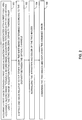
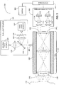
- FIG. 2 is a schematic illustration of a method for combining two images acquired from two different image acquisition paths, operative in accordance with another embodiment of the disclosed technique.
- procedure 180 a first image is acquired through a first image acquisition path and a second image is acquired through a second image acquisition path.
- the first path is associated with a first light and the second path is associated with a second light.
- the image acquisition paths exhibiting non-zero disparity therebetween.
- first imaging sensor 112 acquires a first image through a first optical channel associated with the light generated by first light source 124.
- Second imaging sensor 114 acquires a second image through a first optical channel associated with the light generated by second light source 126.
- one image is shifted relative to the other image.
- the shift is determined according to the disparity between the optical channels.
- processor 103 determines the relative shift between the two acquired images and shifts one image relative to the other.
- intensities and color of the two images are normalized.
- processor 103 normalizes the intensities and the color of the two images.
- procedure 186 the two images are combined into a combined image and displayed.
- processor 103 combines the two images and provides the combined image to display 105 which displays the combined image.
- optical channels 110 1 and 110 2 where physically separated.
- the same optical channel may transmit the light associated with the two image acquisition paths. To that end two optical logical channels are defined within the single optical channel.
- Endoscope system 200 includes a dual channel imager 202, a multi-function light source 204, a processor 203, a display 205 and an endoscope 207.
- Endoscope 207 includes an optical terminal 206, optical fibers 208 1 and 208 2 and an optical channel 210.
- Dual channel imager 202 is located at the proximal end of endoscope 207 and includes a first image sensor 222, a second image sensor 214, first imaging optics 216, second imaging optics 218, first light separator 220 and second light separator 222.
- Multi-function light source 204 includes a first light source 224 and a second light source 226, first light source optics 228, second light source optics 230 an optical combiner 232.
- Multi-function light source 204 optionally includes a short pass filter 234.
- Processor 203 is coupled with display 205 and with dual channel imager 202.
- First imaging optics 216 is optically coupled with first imaging sensor 212 and with first light separator 220 and located therebetween.
- Second imaging optics 218 is optically coupled with first imaging sensor 214 and with first light separator 224 and located therebetween.
- First light separator 220 is optically coupled with optical channel 210 via second exit pupil 240 1 and second light separator 222 is optically coupled with second optical channel 210 via second exit pupil 240 2 .
- Entry pupil 238 1 , optical channel 210, exit pupil 240 1 , first light separator 220 define a first light path with the light generated by first light source 224.
- Entry pupil 238 1 , optical channel 210, exit pupil 240 1 , first light separator 220, first imaging optics 216 and first imaging sensor 212 define a first image acquisition path associated with the light generated by first light source 224.
- Entry pupil 238 2 optical channel 210, exit pupil 240 2 , second light separator 222, define a second light path associated with the light generated by second light source 226.
- Entry pupil 238 2 optical channel 210, exit pupil 240 2 , second light separator 222, second imaging optics 218 and second imaging sensor 214 define a second image acquisition path associated with the light generated by second light source 226. It is noted that the disparity 'D' between entry pupils 238 1 and 238 2 and thus between the two image acquisition paths is larger than zero (i.e., D>0).
- First light source optics 228 is optically coupled with first light source 224 and optical combiner 232 and located therebetween.
- Second light source optics 230 is optically coupled with second light source 226 and optical combiner 232 located therebetween.
- Optical combiner 232 is optically coupled with optical terminal 206.
- Optical terminal 206 is coupled with optical fibers 208 1 and 208 2 .
- Multi-function light source 204 is similar to multi-function light source 104 described above in conjunction with Figure 1A .
- the light generated by first light source 224 exhibits different distinguishable characteristics (e.g., wavelength, polarization or phase) from the light generated by second light source 226.
- the term 'distinguishable characteristics' refers herein to characteristics by which the two lights may be distinguished therebetween, for example, with the aid of optical elements (e.g., filters) or with the aid of processing.
- First light source 224 is typically a white light source such as a Xenon light.
- short pass filter 234 When short pass filter 234 is included in multi-function light source 204, then short pass filter 234 attenuates light exhibiting wavelengths above a cutoff wavelength (e.g., above 700 nanometers).
- Second light source 226 is typically a fluorescence excitation light generated for example by a laser diode (e.g., at a wavelength of 805 nanometers).
- First imaging sensor 212 exhibits sensitivity in the wavelengths range of the light generated by first light source 224 and second imaging sensor exhibits sensitivity in the wavelengths range of the light generated by second light source.
- First imaging sensor 221 and second imaging sensors 224 are, for example CCD sensors or CMOS sensor (i.e., similar to first imaging sensor 112 and second imaging sensor 124 - Figure1 ).
- Optical channel 210 may be constructed from an array of optical elements such lenses, rod lenses mirrors and the like (i.e., also similar to first optical channel 110 1 and Second optical channel 110 2 - Figure 1 ).
- First light source 224 projects the light generated thereby, indicated by a dotted line in Figure 2 , toward first light optics 228.
- First light optics 228 focuses this light onto optical combiner 232.
- Second light source 226 projects the light generated thereby, indicated by a dashed line in Figure 2 , toward second light optics 230.
- Second light optics 230 focuses this light onto optical combiner 232.
- Optical combiner 232 reflects the first light (i.e., generated by first light source 224) and transmits the second light (i.e., generated by second light source 226) to generate a combined light.
- the combined light indicated by a dashed doubled dotted line in Figure 2 , is then transmitted into optical fibers 208 1 and 208 2 by optical terminal 206.
- Optical fibers 208 1 and 208 2 transmit combined light through endoscope 207 and transmit the combined light onto object 236.
- Object 236 reflects the combined light toward entry pupils 238 1 and 238 2 and thus into the optical channel 210.
- Optical channel 210 transmits the reflected combined light which entered through first entry pupil 238 1 via a first optical path within optical channel 210.
- optical channel 210 transmits the reflected combined light, which entered through second entry pupil 238 2 via a second optical path within optical channel 210.
- the light from first optical path exits via first exit pupil 240 1 and is transmitted through first light separator 220.
- the light from second optical path exits via second exit pupil 240 2 and is transmitted through second light separator 222.
- First light separator 220 transmits only light which exhibits characteristics similar to the light generated by first light source 224 toward first imaging optics 216.
- First imaging optics 216 focuses this light onto first imaging sensor 212.
- light separator 222 transmits only light which exhibits characteristics similar to the light generated by second light source 226 toward second imaging optics 218.
- Second imaging optics 218 focuses this light onto second imaging sensor 214.
- First imaging sensor 212 acquires a first image associated only with the first light
- second imaging sensor 214 acquires a second image associated only with the second light.
- First imaging sensor 212 and second imaging sensor 214 provide the acquired images thereby to processor 203.
- Processor 203 processes the image to either display each image separately or combine the two image similar to as described above in conjunction with Figures 1A-1C .
- Endoscope system 250 includes a dual channel imager 252, a multi-function light source 254, a processor 253, a display 255 and an endoscope 257.
- Endoscope 257 includes an optical terminal 256, optical fibers 258 1 and 258 2 .
- Dual channel imager 252 is located at the distal end of endoscope 250 and includes a first image sensor 272, a second image sensor 264, first imaging optics 266, second imaging optics 268, first light separator 270 and second light separator 272.
- Dual channel imager 252 may be embodied as a semiconductor chip located at the tip of endoscope 257.
- Multi-function light source 254 includes a first light source 274 and a second light source 276, first light source optics 278, second light source optics 280 an optical combiner 282.
- Multi-function light source 254 optionally includes a short pass filter 284.
- Processor 253 is coupled with display 255 and with dual channel imager 252.
- First imaging optics 266 is optically coupled with first imaging sensor 262 and with first light separator 270 and located therebetween.
- Second imaging optics 268 is optically coupled with first imaging sensor 264 and with first light separator 274 and located therebetween.
- First light separator 270 entry pupil 288 1 and second separator 272 is optically second entry pupil 288 2 .
- Entry pupil 288 1 , first light separator 270 define a first light path associated with the light generated by first light source 274.
- Entry pupil 288 1 , first light separator 270, first imaging optics 266 and first imaging sensor 262 define a first image acquisition path associated with the light generated by first light source 274.
- Entry pupil 288 2 , second light separator 272 define a second light path the light generated by second light source 276.
- Entry pupil 288 2 , second light separator 272, second imaging optics 268 and second imaging sensor 264 define a second image acquisition path associated with the light generated by second light source 276. It is noted that the disparity 'D' between entry pupils 288 1 and 288 2 and thus between the two image acquisition paths is larger than zero (i.e., D>0).
- First light source optics 278 is optically coupled with first light source 274 and optical combiner 282 and located therebetween.
- Second light source optics 280 is optically coupled with second light source 276 and optical combiner 282 located therebetween.
- Optical combiner 282 is optically coupled with optical terminal 256.
- Optical terminal 256 is coupled with optical fibers 258 1 and 258 2 .
- Multi-function light source 254 is similar to multi-function light source 104 described above in conjunction with Figure 1A .
- the light generated by first light source 274 exhibits different distinguishable characteristics (e.g., wavelength, polarization or phase) from the light generated by second light source 276.
- the term 'distinguishable characteristics' refers herein to characteristics by which the two lights may be distinguished therebetween, for example, with the aid of optical elements (e.g., filters) or with the aid of processing.
- First light source 274 is typically a white light source such as a Xenon light.
- short pass filter 284 is included in multi-function light source 254, then short pass filter 284 attenuates light exhibiting wavelengths above a cutoff wavelength (e.g., above 700 nanometers).
- Second light source 276 is typically a fluorescence excitation light generated for example by a laser diode (e.g., at a wavelength of 805 nanometers).
- First imaging sensor 262 exhibits sensitivity in the wavelengths range of the light generated by first light source 274 and second imaging sensor exhibits sensitivity in the wavelengths range of the light generated by second light source.
- First imaging sensor 262 and second imaging sensors 274 are, for example CCD sensors or CMOS sensor (i.e., similar to first imaging sensor 112 and second imaging sensor 124 - Figure1 ).
- Optical channel 260 may be constructed from an array of optical elements such lenses, rod lenses mirrors and the like (i.e., also similar to first optical channel 110 1 and Second optical channel 110 2 - Figure 1 ).
- First light source 274 projects the light generated thereby, indicated by a dotted line in Figure 2 , toward first light optics 278.
- First light optics 278 focuses this light onto optical combiner 282.
- Second light source 276 projects the light generated thereby, indicated by a dashed line in Figure 2 , toward second light optics 280.
- Second light optics 280 focuses this light onto optical combiner 282.
- Optical combiner 282 reflects the first light (i.e., generated by first light source 274) and transmits the second light (i.e., generated by second light source 276) to generate a combined light.
- the combined light indicated by a dashed doubled dotted line in Figure 2 , is then transmitted into optical fibers 258 1 and 258 2 by optical terminal 256.
- Optical fibers 258 1 and 258 2 transmit combined light through endoscope 257 and transmit the combined light onto object 286.
- Object 286 reflects the combined light toward entry pupils 288 1 and 288 2 and thus into the two image acquisition paths.
- the light passing through entry pupil 288 1 is transmitted through first light separator 270.
- the light passing through entry pupil 288 2 is transmitted through second light separator 272.
- First light separator 270 transmits only light which exhibits characteristics similar to the light generated by first light source 274 toward first imaging optics 266.
- First imaging optics 266 focuses this light onto first imaging sensor 262.
- light separator 272 transmits only light which exhibits characteristics similar to the light generated by second light source 276 toward second imaging optics 268.
- Second imaging optics 268 focuses this light onto second imaging sensor 264.
- First imaging sensor 262 acquires a first image associated only with the first light and second imaging sensor 264 acquires a second image associated only with the second light.
- First imaging sensor 262 and second imaging sensor 264 provide the acquired images thereby to processor 253.
- Processor 253 processes the image to either display each image separately or combine the two image similar to as described above in conjunction with Figures 1A-1C .
Abstract
Description
- The disclosed technique relates to endoscopes in general, and to a dual path endoscope system with non-zero disparity between the two paths and methods therefor in particular.
- A fluorescent endoscope is an imaging system for imaging blood flow, by imaging fluorescence radiation emitted by a fluorescence agent (e.g., a dye) illuminated by light generated by a fluorescent light source. Such an endoscope may be employed, for example, during surgery for visualizing the blood flow, and for evaluating tissue perfusion. In some cases, an additional visible light image of the observed area may be employed to provide anatomical reference to the fluorescent image.
- In known in the art techniques in which both visible and fluorescent light are employed, the fluorescence image and white light image are acquired through the same channel of an endoscope (either in 3D or 2D imaging modes). In other words, two dissimilar imaging modalities are transmitted over the same channel of an endoscope. Although in such known in the art techniques the registration between the two images is simplified, the image acquisition is either interspersed in time (i.e., only white light image or fluorescent image are acquired at a time) or the white illumination is substantially attenuated to allow the relatively weaker fluorescence signal to be brighter than the background white light image.
-
U.S. Patent 8,810,631 to Scott et al , entitled "Augmented stereoscopic visualization for a surgical robot using a captured visible image combined with a fluorescence image and a captured visible image" directs to an endoscope system which includes image capture system and a combination light source. The combination light source produces white light and at least one fluorescence excitation light. The imaging system captures light returned from tissue of a patient. According to one embodiment directed to by Scott et al, the imaging system includes 2 Charge Coupled Device (CCD) sensors. One CCD sensor captures an image of the white light only and the other CCD sensor captures an image of both white and fluorescent light. A processor processes the acquired images to generate a 3D stereoscopic image of both white light and fluorescent light. - It is an object of the disclosed technique to provide a novel dual path endoscope system. The system includes a multi-function light source, an endoscope, a dual channel imager and a processor coupled with the dual channel imager. The multi-function light source produces a first light and a second light and directs the first light and the second light toward an object. The first light exhibits first light characteristics. The second light exhibits second light characteristics different from the first light characteristics. The endoscope includes two light paths, the disparity between the two light paths is larger than zero. Each light path at least includes a respective pupil and a respective light separator coupled with the pupil for transmitting there through a respective one of the first light and the second light, thereby associating the first light and the second light with a respective light path. The dual channel imager at least includes two imaging sensors. Each imaging sensor is associated with a respective one of the light paths. Each imaging sensor is optically coupled with the light separator associated with the respective light path. Each imaging sensor exhibits sensitivity to the characteristics of the respective one of the first light and the second light. A first one of the imaging sensors acquires a first image of the first light reflected of the object and a second one of the imaging sensors acquires a second image of the second light reflected of the object. The processor processes the acquired images.
- The disclosed technique will be understood and appreciated more fully from the following detailed description taken in conjunction with the drawings in which:
-
Figure 1A is a schematic illustration of a dual path endoscope system, constructed and operative in accordance with an embodiment of the disclosed technique; -
Figure 1B is a schematic illustration of two images acquired with a dual path endoscope system such as depicted ofFigure 1A ; -
Figure 1C is a schematic illustration of a combined image acquired with a dual path endoscope system such as depicted ofFigure 1A ; -
Figure 2 is a schematic illustration of a method for combining two images acquired from two different image acquisition channels, operative in accordance with another embodiment of the disclosed technique; -
Figure 3 is a schematic illustration of a dual paths endoscope system, constructed and operative in accordance with a further embodiment of the disclosed technique; and -
Figure 4 , is a schematic illustration of a dual path endoscope system, constructed and operative in accordance with another embodiment of the disclosed technique. - The disclosed technique overcomes the disadvantages of the prior art by providing a dual path endoscope system with non-zero disparity between the two channels and methods therefor. Such a dual path endoscope includes a two-channel imager, which includes two image sensors. One sensor is sensitive to a first light exhibiting respective first light characteristics and the other sensor is sensitive to a second light exhibiting respective second light characteristics different from the first light characteristics. For example, the first light is visible light and the second light is Infrared (IR) light. Typically, a dual path endoscope system according to the disclosed technique is a fluorescent endoscope in which one path is a fluorescence path which employs a fluorescent light (e.g., a laser which excites a fluorescence agent such as a dye) for acquiring a fluorescent image. The other path is a visible light path for acquiring a visible light image. The two images may be displayed separately. The non-zero disparity may be accounted for by employing image processing to generate a 2D image or enables a combined 3D image from the two images. The non-zero disparity physically enables to employ two separate optical paths, thus allowing the visible light path to be independent of the fluorescence light path. The dual channel imager may be located in either distal end of the dual path endoscope or the proximal end of the dual path endoscope. An image sensor may be a single chip sensor containing an integrated color filter or a multi-chip sensor with prisms to separate colors according to wavelength.
- Reference is now made to
Figures 1A ,1B and1C .Figure 1A is a schematic illustration of a dual path endoscope system, generally referenced 100, constructed and operative in accordance with an embodiment of the disclosed technique.Figure 1B is a schematic illustration of two images, 150 and 152 acquired with a system such asendoscope system 100.Figure 1C is a schematic illustration of a combinedimage 154 acquired with a system such asendoscope system 100. - With reference to
Figure 1A ,endoscope system 100 includes adual path imager 102, amulti-function light source 104, aprocessor 103, adisplay 105 and anendoscope 107.Endoscope 107 includes anoptical terminal 106,optical fibers Dual channel imager 102 is located at the proximal end ofendoscope 107 and includes afirst image sensor 112, asecond image sensor 114,first imaging optics 116,second imaging optics 118,first light separator 120 andsecond light separator 122.Multi-function light source 104 includes afirst light source 124 and asecond light source 126, firstlight source optics 128, secondlight source optics 130 anoptical combiner 132.Multi-function light source 104 optionally includes ashort pass filter 134. -
Processor 103 is coupled withdisplay 105 and withdual channel imager 102.First imaging optics 116 is optically coupled withfirst imaging sensor 112 and withfirst light separator 120 and located therebetween.Second imaging optics 118 is optically coupled withfirst imaging sensor 114 and withfirst light separator 122 and located therebetween.First light separator 120 is optically coupled with first optical channel 1101 andsecond light separator 122 is optically coupled with second optical channel 1102.Entry pupil 1381, first optical channel 1101,first light separator 120 define a first light path.Entry pupil 1381, first optical channel 1101,first light separator 120,first imaging optics 116 andfirst imaging sensor 112 define a first image acquisition channel associated with the light generated byfirst light source 124.Entry pupil 1382, Second optical channel 1102,second light separator 122, define a second light path.Entry pupil 1382, Second optical channel 1102, secondlight separator 122,second imaging optics 118 andsecond imaging sensor 114 define a second image acquisition channel associated with the light generated by secondlight source 126. It is noted that the disparity 'D' betweenentry pupils - First
light source optics 128 is optically coupled with firstlight source 124 andoptical combiner 132 and located therebetween. Secondlight source optics 130 is optically coupled with secondlight source 126 andoptical combiner 132 located therebetween.Optical combiner 132 is optically coupled withoptical terminal 106.Optical terminal 106 is coupled withoptical fibers - The light generated by first
light source 124 exhibits different distinguishable light characteristics (e.g., different wavelength, different polarization or different phase) from the light characteristics generated by secondlight source 126. The term 'distinguishable light characteristics' refers herein to characteristics by which the two lights may be distinguished therebetween, for example, with the aid of optical elements (e.g., filters) or with the aid of processing. Firstlight source 124 is typically a white light source such as a Xenon light. Whenshort pass filter 134 is included in multi-functionlight source 104, thenshort pass filter 134 attenuates light exhibiting wavelengths above a cutoff wavelength (e.g., above 700 nanometers). Secondlight source 126 is typically a fluorescence excitation light generated for example by a laser diode (e.g., at a wavelength of 805 nanometers). InFigure 1A ,light source 104 is depicted as including two light sources. However, in general,light source 104 may include more than two sources exhibiting distinguishable characteristics therebetween. -
First imaging sensor 112 exhibits sensitivity in the wavelengths range of the light generated by firstlight source 124 and second imaging sensor exhibits sensitivity in the wavelengths range of the light generated by second light source.First imaging sensor 112 andsecond imaging sensors 124 are, for example CCD sensors or Complementary Metal Oxide Semiconductor (CMOS) sensor. First optical channel 1101 and second optical channel 1102 are position alongendoscope 107 and may be constructed from an array of optical elements such lenses, rod lenses mirrors and the like. - First
light source 124 projects the light generated thereby, indicated by a dotted line inFigure 1A , toward firstlight optics 128. Firstlight optics 128 focuses this light ontooptical combiner 132. Secondlight source 126 projects the light generated thereby, indicated by a dashed line inFigure 1A , toward secondlight optics 130. Secondlight optics 130 focuses this light ontooptical combiner 132.Optical combiner 132 reflects the first light (i.e., generated by first light source 124) and transmits the second light (i.e., generated by second light source 126) to generate a combined light. The combined light, indicated by a dashed double dotted line inFigure 1A , is then transmitted intooptical fibers optical terminal 106.Optical fibers endoscope 107, which transmit the combined light ontoobject 136. Alternatively,light source 104 may direct the light generated by firstlight source 124 and the light generated bysecond lights source 126 separate from each other, through endoscope 107 (e.g., through separate light channels such as fiber optics) ontoobject 136. As a further alternative,light source 104 directs the combined light generated by firstlight source 124 and the light generated bysecond lights source 126 throughendoscope 107 via one or more light channels ontoobject 136. In other words,endoscope 107 may include one or more light channels through which multi-functionlight source 104 may direct the light generated thereby. -
Object 136 reflects the combined light toward two optical channels, first optical channel 1101 and second optical channel 1102 viarespective entry pupils channel imager 102. The light from first optical channel is transmitted through firstlight separator 120. Firstlight separator 120 transmits only light which exhibits characteristics similar to the light generated by firstlight source 124 towardfirst imaging optics 116.First imaging optics 116 focuses this light ontofirst imaging sensor 112. Similarly,light separator 122 transmits only light which exhibits characteristics similar to the light generated by secondlight source 126 towardsecond imaging optics 118.Second imaging optics 118 focuses this light ontosecond imaging sensor 114.First imaging sensor 112 acquires a first image associated only with the first light andsecond imaging sensor 114 acquires a second image associated only with the second light.First imaging sensor 112 andsecond imaging sensor 114 provide the acquired images thereby toprocessor 103. - According to one alternative,
processor 103 processes the acquired image separately (e.g., filtering) and provides each image to display 107 which display the images separately. With reference toFigure 1B ,image 150 is and exemplary image acquired byfirst imaging sensor 112 referred to herein also as 'right eye image'. Figure 152 is an exemplary image acquired bysecond imaging sensor 114 referred to herein also as 'left eye image'. The light emitted by firstlight source 124 to generatedimage 150 is white light in the visible part of the spectrum. The light emitted by secondlight source 126 to generatedimage 152 is in the IR part of the spectrum. - According to another alternative,
processor 103 processes the acquired images and combines the two acquired images into a single combined image. To generate a combined image from the right eye image and the left eye image,processor 103 determines the shift of the second image, relative to the first image, based on the disparity `D'.Processor 103 then shifts the second image according to the determined shift and further normalizes the intensities and color of the two images.Processor 103 than combines the two images (e.g., by creating a pseudo-color overlay of the fluorescence image on the white light image) and provides the combined image to display 107 which displays the combined image. With reference toFigure 1C ,image 154 is an exemplary combined image. - Reference is now made to
Figure 2 , which is a schematic illustration of a method for combining two images acquired from two different image acquisition paths, operative in accordance with another embodiment of the disclosed technique. Inprocedure 180, a first image is acquired through a first image acquisition path and a second image is acquired through a second image acquisition path. The first path is associated with a first light and the second path is associated with a second light. The image acquisition paths exhibiting non-zero disparity therebetween. With reference toFigure 1A ,first imaging sensor 112 acquires a first image through a first optical channel associated with the light generated by firstlight source 124.Second imaging sensor 114 acquires a second image through a first optical channel associated with the light generated by secondlight source 126. - In
procedure 182, one image is shifted relative to the other image. The shift is determined according to the disparity between the optical channels. With reference toFigure 1A ,processor 103 determines the relative shift between the two acquired images and shifts one image relative to the other. - In
procedure 184, intensities and color of the two images are normalized. With reference toFigure 1A ,processor 103 normalizes the intensities and the color of the two images. - In
procedure 186, the two images are combined into a combined image and displayed. With reference toFigure 1A ,processor 103 combines the two images and provides the combined image to display 105 which displays the combined image. - In the embodiment described herein above in conjunction with
Figure 1A , optical channels 1101 and 1102 where physically separated. According to a further embodiment of the disclosed technique, the same optical channel may transmit the light associated with the two image acquisition paths. To that end two optical logical channels are defined within the single optical channel. - Reference is now made to
Figure 3 , which is a schematic illustration of a dual path endoscope system, generally referenced 200, constructed and operative in accordance with a further embodiment of the disclosed technique.Endoscope system 200 includes adual channel imager 202, a multi-functionlight source 204, aprocessor 203, adisplay 205 and anendoscope 207.Endoscope 207 includes anoptical terminal 206,optical fibers optical channel 210.Dual channel imager 202 is located at the proximal end ofendoscope 207 and includes afirst image sensor 222, asecond image sensor 214,first imaging optics 216,second imaging optics 218,first light separator 220 and secondlight separator 222. Multi-functionlight source 204 includes a firstlight source 224 and a secondlight source 226, firstlight source optics 228, secondlight source optics 230 anoptical combiner 232. Multi-functionlight source 204 optionally includes ashort pass filter 234. -
Processor 203 is coupled withdisplay 205 and withdual channel imager 202.First imaging optics 216 is optically coupled withfirst imaging sensor 212 and with firstlight separator 220 and located therebetween.Second imaging optics 218 is optically coupled withfirst imaging sensor 214 and with firstlight separator 224 and located therebetween. Firstlight separator 220 is optically coupled withoptical channel 210 viasecond exit pupil 2401 and secondlight separator 222 is optically coupled with secondoptical channel 210 viasecond exit pupil 2402.Entry pupil 2381,optical channel 210,exit pupil 2401,first light separator 220 define a first light path with the light generated by firstlight source 224.Entry pupil 2381,optical channel 210,exit pupil 2401,first light separator 220,first imaging optics 216 andfirst imaging sensor 212 define a first image acquisition path associated with the light generated by firstlight source 224.Entry pupil 2382optical channel 210,exit pupil 2402, secondlight separator 222, define a second light path associated with the light generated by secondlight source 226.Entry pupil 2382optical channel 210,exit pupil 2402, secondlight separator 222,second imaging optics 218 andsecond imaging sensor 214 define a second image acquisition path associated with the light generated by secondlight source 226. It is noted that the disparity 'D' betweenentry pupils - First
light source optics 228 is optically coupled with firstlight source 224 andoptical combiner 232 and located therebetween. Secondlight source optics 230 is optically coupled with secondlight source 226 andoptical combiner 232 located therebetween.Optical combiner 232 is optically coupled withoptical terminal 206.Optical terminal 206 is coupled withoptical fibers - Multi-function
light source 204 is similar to multi-functionlight source 104 described above in conjunction withFigure 1A . The light generated by firstlight source 224 exhibits different distinguishable characteristics (e.g., wavelength, polarization or phase) from the light generated by secondlight source 226. The term 'distinguishable characteristics' refers herein to characteristics by which the two lights may be distinguished therebetween, for example, with the aid of optical elements (e.g., filters) or with the aid of processing. Firstlight source 224 is typically a white light source such as a Xenon light. Whenshort pass filter 234 is included in multi-functionlight source 204, thenshort pass filter 234 attenuates light exhibiting wavelengths above a cutoff wavelength (e.g., above 700 nanometers). Secondlight source 226 is typically a fluorescence excitation light generated for example by a laser diode (e.g., at a wavelength of 805 nanometers).First imaging sensor 212 exhibits sensitivity in the wavelengths range of the light generated by firstlight source 224 and second imaging sensor exhibits sensitivity in the wavelengths range of the light generated by second light source. First imaging sensor 221 andsecond imaging sensors 224 are, for example CCD sensors or CMOS sensor (i.e., similar tofirst imaging sensor 112 and second imaging sensor 124 -Figure1 ).Optical channel 210 may be constructed from an array of optical elements such lenses, rod lenses mirrors and the like (i.e., also similar to first optical channel 1101 and Second optical channel 1102 -Figure 1 ). - First
light source 224 projects the light generated thereby, indicated by a dotted line inFigure 2 , toward firstlight optics 228. Firstlight optics 228 focuses this light ontooptical combiner 232. Secondlight source 226 projects the light generated thereby, indicated by a dashed line inFigure 2 , toward secondlight optics 230. Secondlight optics 230 focuses this light ontooptical combiner 232.Optical combiner 232 reflects the first light (i.e., generated by first light source 224) and transmits the second light (i.e., generated by second light source 226) to generate a combined light. The combined light, indicated by a dashed doubled dotted line inFigure 2 , is then transmitted intooptical fibers optical terminal 206.Optical fibers endoscope 207 and transmit the combined light ontoobject 236. -
Object 236 reflects the combined light towardentry pupils optical channel 210.Optical channel 210 transmits the reflected combined light which entered throughfirst entry pupil 2381 via a first optical path withinoptical channel 210. Similarly,optical channel 210 transmits the reflected combined light, which entered throughsecond entry pupil 2382 via a second optical path withinoptical channel 210. The light from first optical path exits viafirst exit pupil 2401 and is transmitted through firstlight separator 220. The light from second optical path exits viasecond exit pupil 2402 and is transmitted through secondlight separator 222. Firstlight separator 220 transmits only light which exhibits characteristics similar to the light generated by firstlight source 224 towardfirst imaging optics 216.First imaging optics 216 focuses this light ontofirst imaging sensor 212. Similarly,light separator 222 transmits only light which exhibits characteristics similar to the light generated by secondlight source 226 towardsecond imaging optics 218.Second imaging optics 218 focuses this light ontosecond imaging sensor 214.First imaging sensor 212 acquires a first image associated only with the first light andsecond imaging sensor 214 acquires a second image associated only with the second light.First imaging sensor 212 andsecond imaging sensor 214 provide the acquired images thereby toprocessor 203.Processor 203 processes the image to either display each image separately or combine the two image similar to as described above in conjunction withFigures 1A-1C . - Reference is now made to
Figure 4 , which is a schematic illustration of a dual paths endoscope system, generally referenced 250, constructed and operative in accordance with another embodiment of the disclosed technique.Endoscope system 250 includes adual channel imager 252, a multi-functionlight source 254, aprocessor 253, adisplay 255 and anendoscope 257.Endoscope 257 includes anoptical terminal 256,optical fibers Dual channel imager 252 is located at the distal end ofendoscope 250 and includes afirst image sensor 272, asecond image sensor 264,first imaging optics 266,second imaging optics 268,first light separator 270 and secondlight separator 272.Dual channel imager 252 may be embodied as a semiconductor chip located at the tip ofendoscope 257. Multi-functionlight source 254 includes a firstlight source 274 and a secondlight source 276, firstlight source optics 278, secondlight source optics 280 anoptical combiner 282. Multi-functionlight source 254 optionally includes ashort pass filter 284. -
Processor 253 is coupled withdisplay 255 and withdual channel imager 252.First imaging optics 266 is optically coupled withfirst imaging sensor 262 and with firstlight separator 270 and located therebetween.Second imaging optics 268 is optically coupled withfirst imaging sensor 264 and with firstlight separator 274 and located therebetween. Firstlight separator 270entry pupil 2881 andsecond separator 272 is opticallysecond entry pupil 2882.Entry pupil 2881,first light separator 270 define a first light path associated with the light generated by firstlight source 274.Entry pupil 2881,first light separator 270,first imaging optics 266 andfirst imaging sensor 262 define a first image acquisition path associated with the light generated by firstlight source 274.Entry pupil 2882, secondlight separator 272 define a second light path the light generated by secondlight source 276.Entry pupil 2882, secondlight separator 272,second imaging optics 268 andsecond imaging sensor 264 define a second image acquisition path associated with the light generated by secondlight source 276. It is noted that the disparity 'D' betweenentry pupils - First
light source optics 278 is optically coupled with firstlight source 274 andoptical combiner 282 and located therebetween. Secondlight source optics 280 is optically coupled with secondlight source 276 andoptical combiner 282 located therebetween.Optical combiner 282 is optically coupled withoptical terminal 256.Optical terminal 256 is coupled withoptical fibers - Multi-function
light source 254 is similar to multi-functionlight source 104 described above in conjunction withFigure 1A . The light generated by firstlight source 274 exhibits different distinguishable characteristics (e.g., wavelength, polarization or phase) from the light generated by secondlight source 276. The term 'distinguishable characteristics' refers herein to characteristics by which the two lights may be distinguished therebetween, for example, with the aid of optical elements (e.g., filters) or with the aid of processing. Firstlight source 274 is typically a white light source such as a Xenon light. Whenshort pass filter 284 is included in multi-functionlight source 254, thenshort pass filter 284 attenuates light exhibiting wavelengths above a cutoff wavelength (e.g., above 700 nanometers). Secondlight source 276 is typically a fluorescence excitation light generated for example by a laser diode (e.g., at a wavelength of 805 nanometers).First imaging sensor 262 exhibits sensitivity in the wavelengths range of the light generated by firstlight source 274 and second imaging sensor exhibits sensitivity in the wavelengths range of the light generated by second light source.First imaging sensor 262 andsecond imaging sensors 274 are, for example CCD sensors or CMOS sensor (i.e., similar tofirst imaging sensor 112 and second imaging sensor 124 -Figure1 ). Optical channel 260 may be constructed from an array of optical elements such lenses, rod lenses mirrors and the like (i.e., also similar to first optical channel 1101 and Second optical channel 1102 -Figure 1 ). - First
light source 274 projects the light generated thereby, indicated by a dotted line inFigure 2 , toward firstlight optics 278. Firstlight optics 278 focuses this light ontooptical combiner 282. Secondlight source 276 projects the light generated thereby, indicated by a dashed line inFigure 2 , toward secondlight optics 280. Secondlight optics 280 focuses this light ontooptical combiner 282.Optical combiner 282 reflects the first light (i.e., generated by first light source 274) and transmits the second light (i.e., generated by second light source 276) to generate a combined light. The combined light, indicated by a dashed doubled dotted line inFigure 2 , is then transmitted intooptical fibers optical terminal 256.Optical fibers endoscope 257 and transmit the combined light ontoobject 286. -
Object 286 reflects the combined light towardentry pupils entry pupil 2881 is transmitted through firstlight separator 270. The light passing throughentry pupil 2882 is transmitted through secondlight separator 272. Firstlight separator 270 transmits only light which exhibits characteristics similar to the light generated by firstlight source 274 towardfirst imaging optics 266.First imaging optics 266 focuses this light ontofirst imaging sensor 262. Similarly,light separator 272 transmits only light which exhibits characteristics similar to the light generated by secondlight source 276 towardsecond imaging optics 268.Second imaging optics 268 focuses this light ontosecond imaging sensor 264.First imaging sensor 262 acquires a first image associated only with the first light andsecond imaging sensor 264 acquires a second image associated only with the second light.First imaging sensor 262 andsecond imaging sensor 264 provide the acquired images thereby toprocessor 253.Processor 253 processes the image to either display each image separately or combine the two image similar to as described above in conjunction withFigures 1A-1C . - It will be appreciated by persons skilled in the art that the disclosed techniques are not limited to what has been particularly shown and described hereinabove. Rather the scope of the disclosed techniques are defined only by the claims, which follow.
Claims (14)
- A dual path endoscope system comprising:a multi-function light source producing a first light and a second light and directing said first light and said second light toward an object, said first light exhibiting first light characteristics, said second light exhibiting second light characteristics different from said first light characteristics,an endoscope, said endoscope including two light paths, the disparity between said two light paths being larger than zero, each light path at least including:a respective pupil; anda respective light separator optically coupled with said pupil for transmitting there through a respective one of said first light and said second light, thereby associating said first light and said second light with a respective light path;a dual channel imager at least including two imaging sensors, each imaging sensor being associated with a respective one of said light paths, each imaging sensor being optically coupled with the light separator associated with the respective light path, each imaging sensor exhibiting sensitivity to the characteristics of said respective one of said first light and said second light, a first one of said imaging sensors acquires a first image of said first light reflected of said object and a second one of said imaging sensors acquires a second image of said second light reflected of said object; anda processor, coupled with said dual channel imager for processing said acquired images.
- The system according to claim 1, wherein said dual channel imager is located at the proximal end said endoscope.
- The system according to claim 2, wherein said two light paths further including at least one optical channel within said endoscope.
- The system according to claim 2, wherein said endoscope further including:an optical terminal for receiving light from said multi-function light source; andat least one optical fiber, coupled with said optical terminal for transmitting said light through said endoscope.
- The system according to claim 1, wherein said dual channel imager is located at the distal end of said endoscope.
- The system according to claim 1, wherein said first light characteristics and said second light characteristics are selected from the group consisting of:wavelength;polarization; andphase
- The system according to claim 1, wherein said processor processes said first image and said second image, separately.
- The system according to claim 1, wherein said processor processes said first image and said second image and combines said first image and said second image into a single combined image by determining the shift of one of said first image and said second image relative to the other image based on said disparity and shifting said other image according to the determined shift and combining said first image and said second image.
- The system according to claim 8, wherein said processor further normalizes the intensities and color of said first image and said second image.
- The system according to claim 8, wherein said processor combines the two acquired images by creating a pseudo-color overlay of said second image over said first image.
- The system according to claim 1, further including a display for displaying at least one image provided by said processor.
- The system according to claim 1, wherein said multi-function light source includes a first light source generating said first light and a second light source generating said second light.
- The system according to claim 12, wherein said multi-function light source further includes:a first light source optics optically coupled with said first light source;a second light source optics optically coupled with said first light source; andan optical combiner optically coupled with said first light source optics and with said second light source optics for generating a combined light from said first light and said second light and directing said combined light toward said object.
- The system according to claim 12, wherein said multi-function light source further includes a short pass filter optically coupled with said first light source and with said first light source optics for attenuating light exhibiting wavelengths above a cutoff wavelength.
Applications Claiming Priority (2)
| Application Number | Priority Date | Filing Date | Title |
|---|---|---|---|
| US201662330282P | 2016-05-02 | 2016-05-02 | |
| US201762489463P | 2017-04-25 | 2017-04-25 |
Publications (2)
| Publication Number | Publication Date |
|---|---|
| EP3241481A1 true EP3241481A1 (en) | 2017-11-08 |
| EP3241481B1 EP3241481B1 (en) | 2022-06-29 |
Family
ID=60158725
Family Applications (1)
| Application Number | Title | Priority Date | Filing Date |
|---|---|---|---|
| EP17000751.2A Active EP3241481B1 (en) | 2016-05-02 | 2017-05-02 | Dual path endoscope |
Country Status (2)
| Country | Link |
|---|---|
| US (2) | US10447906B2 (en) |
| EP (1) | EP3241481B1 (en) |
Families Citing this family (5)
| Publication number | Priority date | Publication date | Assignee | Title |
|---|---|---|---|---|
| CN108535227B (en) * | 2018-04-02 | 2020-01-17 | 大连理工大学 | Application of CdTe QD @ ZIF-8 nanocomposite in detection of chromium ions |
| JP2019203796A (en) * | 2018-05-23 | 2019-11-28 | 株式会社東芝 | Optical inspection apparatus and optical inspection method |
| JP6461411B1 (en) * | 2018-07-13 | 2019-01-30 | パナソニック株式会社 | Endoscope system |
| CN110381272B (en) * | 2019-08-22 | 2022-05-13 | 睿镞科技(北京)有限责任公司 | Image sensor combination system and device for generating single and compound visual field images |
| DE102021110611B3 (en) | 2021-04-26 | 2022-08-11 | Karl Storz Se & Co. Kg | Medical imaging device, in particular stereo endoscope or stereo exoscope |
Citations (5)
| Publication number | Priority date | Publication date | Assignee | Title |
|---|---|---|---|---|
| US5749830A (en) * | 1993-12-03 | 1998-05-12 | Olympus Optical Co., Ltd. | Fluorescent endoscope apparatus |
| US6471642B1 (en) * | 1999-10-08 | 2002-10-29 | Olympus Optical Co., Ltd. | Rigid endoscope optical system |
| US7405877B1 (en) * | 2003-02-10 | 2008-07-29 | Visionsense Ltd. | Stereoscopic endoscope |
| US20130041221A1 (en) * | 2011-08-12 | 2013-02-14 | Intuitive Surgical Operations, Inc. | Image capture unit and an imaging pipeline with enhanced color performance in a surgical instrument and method |
| US20140031659A1 (en) * | 2012-07-25 | 2014-01-30 | Intuitive Surgical Operations, Inc. | Efficient and interactive bleeding detection in a surgical system |
Family Cites Families (13)
| Publication number | Priority date | Publication date | Assignee | Title |
|---|---|---|---|---|
| US5751341A (en) * | 1993-01-05 | 1998-05-12 | Vista Medical Technologies, Inc. | Stereoscopic endoscope system |
| CN1289239A (en) * | 1998-01-26 | 2001-03-28 | 麻省理工学院 | Fluorescence imaging endoscope |
| US20050182434A1 (en) | 2000-08-11 | 2005-08-18 | National Research Council Of Canada | Method and apparatus for performing intra-operative angiography |
| IL162251A0 (en) * | 2004-05-31 | 2005-11-20 | Medigus Ltd | A reusable laparoscopic or endoscopic camera head |
| US20060293556A1 (en) * | 2005-05-16 | 2006-12-28 | Garner David M | Endoscope with remote control module or camera |
| US8169468B2 (en) * | 2008-04-26 | 2012-05-01 | Intuitive Surgical Operations, Inc. | Augmented stereoscopic visualization for a surgical robot |
| JP2010082040A (en) * | 2008-09-30 | 2010-04-15 | Fujifilm Corp | Endoscope system |
| US20110043612A1 (en) * | 2009-07-31 | 2011-02-24 | Inneroptic Technology Inc. | Dual-tube stereoscope |
| DE102010053882A1 (en) * | 2010-12-09 | 2012-06-14 | Schölly Fiberoptic GmbH | endoscope |
| US8784301B2 (en) * | 2011-08-12 | 2014-07-22 | Intuitive Surgical Operations, Inc. | Image capture unit and method with an extended depth of field |
| EP2755544B1 (en) | 2011-09-13 | 2019-12-25 | Visionsense Ltd | Proximal high definition endoscope |
| US9277205B2 (en) * | 2012-05-14 | 2016-03-01 | Intuitive Surgical Operations, Inc. | Single-chip sensor multi-function imaging |
| IL236418A (en) | 2014-12-23 | 2016-07-31 | Visionsense Ltd | Rotatable oblique viewing stereoendoscope |
-
2017
- 2017-04-27 US US15/499,363 patent/US10447906B2/en active Active
- 2017-05-02 EP EP17000751.2A patent/EP3241481B1/en active Active
-
2019
- 2019-09-05 US US16/561,743 patent/US10805512B2/en active Active
Patent Citations (5)
| Publication number | Priority date | Publication date | Assignee | Title |
|---|---|---|---|---|
| US5749830A (en) * | 1993-12-03 | 1998-05-12 | Olympus Optical Co., Ltd. | Fluorescent endoscope apparatus |
| US6471642B1 (en) * | 1999-10-08 | 2002-10-29 | Olympus Optical Co., Ltd. | Rigid endoscope optical system |
| US7405877B1 (en) * | 2003-02-10 | 2008-07-29 | Visionsense Ltd. | Stereoscopic endoscope |
| US20130041221A1 (en) * | 2011-08-12 | 2013-02-14 | Intuitive Surgical Operations, Inc. | Image capture unit and an imaging pipeline with enhanced color performance in a surgical instrument and method |
| US20140031659A1 (en) * | 2012-07-25 | 2014-01-30 | Intuitive Surgical Operations, Inc. | Efficient and interactive bleeding detection in a surgical system |
Also Published As
| Publication number | Publication date |
|---|---|
| US20170318207A1 (en) | 2017-11-02 |
| US20190394371A1 (en) | 2019-12-26 |
| US10805512B2 (en) | 2020-10-13 |
| US10447906B2 (en) | 2019-10-15 |
| EP3241481B1 (en) | 2022-06-29 |
Similar Documents
| Publication | Publication Date | Title |
|---|---|---|
| US10805512B2 (en) | Dual path endoscope | |
| US11788966B2 (en) | Imaging system | |
| US9906739B2 (en) | Image pickup device and image pickup method | |
| CN107072520B (en) | Endoscope system for parallel imaging with visible and infrared wavelengths | |
| JP6184571B2 (en) | Fluorescence observation endoscope system | |
| JP4799109B2 (en) | Electronic endoscope device | |
| EP1795111A1 (en) | Removable filter unit and endoscope | |
| JP2010082040A (en) | Endoscope system | |
| US11160442B2 (en) | Endoscope apparatus | |
| US20230308628A1 (en) | Medical imaging system, medical imaging device, and operation method | |
| CN108778088B (en) | Living body observation system | |
| JP5570352B2 (en) | Imaging device | |
| US20180092519A1 (en) | Infrared fluorescence observation device | |
| JPH05344997A (en) | Medical stereoscopic microscope | |
| WO2019087640A1 (en) | Light source device | |
| CN111568549A (en) | Visualization system with real-time imaging function | |
| US20230397801A1 (en) | Medical imaging system, medical imaging device, and operation method | |
| US20200252601A1 (en) | Imaging system and synchronization control method | |
| JP6138386B1 (en) | Endoscope apparatus and endoscope system | |
| JP2022108089A (en) | projection device | |
| JP2011188928A (en) | Fluorescent endoscope apparatus |
Legal Events
| Date | Code | Title | Description |
|---|---|---|---|
| PUAI | Public reference made under article 153(3) epc to a published international application that has entered the european phase |
Free format text: ORIGINAL CODE: 0009012 |
|
| STAA | Information on the status of an ep patent application or granted ep patent |
Free format text: STATUS: THE APPLICATION HAS BEEN PUBLISHED |
|
| AK | Designated contracting states |
Kind code of ref document: A1 Designated state(s): AL AT BE BG CH CY CZ DE DK EE ES FI FR GB GR HR HU IE IS IT LI LT LU LV MC MK MT NL NO PL PT RO RS SE SI SK SM TR |
|
| AX | Request for extension of the european patent |
Extension state: BA ME |
|
| STAA | Information on the status of an ep patent application or granted ep patent |
Free format text: STATUS: REQUEST FOR EXAMINATION WAS MADE |
|
| 17P | Request for examination filed |
Effective date: 20180508 |
|
| RBV | Designated contracting states (corrected) |
Designated state(s): AL AT BE BG CH CY CZ DE DK EE ES FI FR GB GR HR HU IE IS IT LI LT LU LV MC MK MT NL NO PL PT RO RS SE SI SK SM TR |
|
| STAA | Information on the status of an ep patent application or granted ep patent |
Free format text: STATUS: EXAMINATION IS IN PROGRESS |
|
| 17Q | First examination report despatched |
Effective date: 20180720 |
|
| STAA | Information on the status of an ep patent application or granted ep patent |
Free format text: STATUS: EXAMINATION IS IN PROGRESS |
|
| GRAP | Despatch of communication of intention to grant a patent |
Free format text: ORIGINAL CODE: EPIDOSNIGR1 |
|
| STAA | Information on the status of an ep patent application or granted ep patent |
Free format text: STATUS: GRANT OF PATENT IS INTENDED |
|
| INTG | Intention to grant announced |
Effective date: 20211126 |
|
| GRAS | Grant fee paid |
Free format text: ORIGINAL CODE: EPIDOSNIGR3 |
|
| GRAA | (expected) grant |
Free format text: ORIGINAL CODE: 0009210 |
|
| STAA | Information on the status of an ep patent application or granted ep patent |
Free format text: STATUS: THE PATENT HAS BEEN GRANTED |
|
| AK | Designated contracting states |
Kind code of ref document: B1 Designated state(s): AL AT BE BG CH CY CZ DE DK EE ES FI FR GB GR HR HU IE IS IT LI LT LU LV MC MK MT NL NO PL PT RO RS SE SI SK SM TR |
|
| REG | Reference to a national code |
Ref country code: CH Ref legal event code: EP |
|
| REG | Reference to a national code |
Ref country code: AT Ref legal event code: REF Ref document number: 1500737 Country of ref document: AT Kind code of ref document: T Effective date: 20220715 |
|
| REG | Reference to a national code |
Ref country code: IE Ref legal event code: FG4D |
|
| REG | Reference to a national code |
Ref country code: DE Ref legal event code: R096 Ref document number: 602017058920 Country of ref document: DE |
|
| REG | Reference to a national code |
Ref country code: LT Ref legal event code: MG9D |
|
| PG25 | Lapsed in a contracting state [announced via postgrant information from national office to epo] |
Ref country code: SE Free format text: LAPSE BECAUSE OF FAILURE TO SUBMIT A TRANSLATION OF THE DESCRIPTION OR TO PAY THE FEE WITHIN THE PRESCRIBED TIME-LIMIT Effective date: 20220629 Ref country code: NO Free format text: LAPSE BECAUSE OF FAILURE TO SUBMIT A TRANSLATION OF THE DESCRIPTION OR TO PAY THE FEE WITHIN THE PRESCRIBED TIME-LIMIT Effective date: 20220929 Ref country code: LT Free format text: LAPSE BECAUSE OF FAILURE TO SUBMIT A TRANSLATION OF THE DESCRIPTION OR TO PAY THE FEE WITHIN THE PRESCRIBED TIME-LIMIT Effective date: 20220629 Ref country code: HR Free format text: LAPSE BECAUSE OF FAILURE TO SUBMIT A TRANSLATION OF THE DESCRIPTION OR TO PAY THE FEE WITHIN THE PRESCRIBED TIME-LIMIT Effective date: 20220629 Ref country code: GR Free format text: LAPSE BECAUSE OF FAILURE TO SUBMIT A TRANSLATION OF THE DESCRIPTION OR TO PAY THE FEE WITHIN THE PRESCRIBED TIME-LIMIT Effective date: 20220930 Ref country code: FI Free format text: LAPSE BECAUSE OF FAILURE TO SUBMIT A TRANSLATION OF THE DESCRIPTION OR TO PAY THE FEE WITHIN THE PRESCRIBED TIME-LIMIT Effective date: 20220629 Ref country code: BG Free format text: LAPSE BECAUSE OF FAILURE TO SUBMIT A TRANSLATION OF THE DESCRIPTION OR TO PAY THE FEE WITHIN THE PRESCRIBED TIME-LIMIT Effective date: 20220929 |
|
| REG | Reference to a national code |
Ref country code: NL Ref legal event code: MP Effective date: 20220629 |
|
| REG | Reference to a national code |
Ref country code: AT Ref legal event code: MK05 Ref document number: 1500737 Country of ref document: AT Kind code of ref document: T Effective date: 20220629 |
|
| PG25 | Lapsed in a contracting state [announced via postgrant information from national office to epo] |
Ref country code: RS Free format text: LAPSE BECAUSE OF FAILURE TO SUBMIT A TRANSLATION OF THE DESCRIPTION OR TO PAY THE FEE WITHIN THE PRESCRIBED TIME-LIMIT Effective date: 20220629 Ref country code: LV Free format text: LAPSE BECAUSE OF FAILURE TO SUBMIT A TRANSLATION OF THE DESCRIPTION OR TO PAY THE FEE WITHIN THE PRESCRIBED TIME-LIMIT Effective date: 20220629 |
|
| PG25 | Lapsed in a contracting state [announced via postgrant information from national office to epo] |
Ref country code: NL Free format text: LAPSE BECAUSE OF FAILURE TO SUBMIT A TRANSLATION OF THE DESCRIPTION OR TO PAY THE FEE WITHIN THE PRESCRIBED TIME-LIMIT Effective date: 20220629 |
|
| PG25 | Lapsed in a contracting state [announced via postgrant information from national office to epo] |
Ref country code: SM Free format text: LAPSE BECAUSE OF FAILURE TO SUBMIT A TRANSLATION OF THE DESCRIPTION OR TO PAY THE FEE WITHIN THE PRESCRIBED TIME-LIMIT Effective date: 20220629 Ref country code: SK Free format text: LAPSE BECAUSE OF FAILURE TO SUBMIT A TRANSLATION OF THE DESCRIPTION OR TO PAY THE FEE WITHIN THE PRESCRIBED TIME-LIMIT Effective date: 20220629 Ref country code: RO Free format text: LAPSE BECAUSE OF FAILURE TO SUBMIT A TRANSLATION OF THE DESCRIPTION OR TO PAY THE FEE WITHIN THE PRESCRIBED TIME-LIMIT Effective date: 20220629 Ref country code: PT Free format text: LAPSE BECAUSE OF FAILURE TO SUBMIT A TRANSLATION OF THE DESCRIPTION OR TO PAY THE FEE WITHIN THE PRESCRIBED TIME-LIMIT Effective date: 20221031 Ref country code: ES Free format text: LAPSE BECAUSE OF FAILURE TO SUBMIT A TRANSLATION OF THE DESCRIPTION OR TO PAY THE FEE WITHIN THE PRESCRIBED TIME-LIMIT Effective date: 20220629 Ref country code: EE Free format text: LAPSE BECAUSE OF FAILURE TO SUBMIT A TRANSLATION OF THE DESCRIPTION OR TO PAY THE FEE WITHIN THE PRESCRIBED TIME-LIMIT Effective date: 20220629 Ref country code: AT Free format text: LAPSE BECAUSE OF FAILURE TO SUBMIT A TRANSLATION OF THE DESCRIPTION OR TO PAY THE FEE WITHIN THE PRESCRIBED TIME-LIMIT Effective date: 20220629 |
|
| PG25 | Lapsed in a contracting state [announced via postgrant information from national office to epo] |
Ref country code: PL Free format text: LAPSE BECAUSE OF FAILURE TO SUBMIT A TRANSLATION OF THE DESCRIPTION OR TO PAY THE FEE WITHIN THE PRESCRIBED TIME-LIMIT Effective date: 20220629 Ref country code: IS Free format text: LAPSE BECAUSE OF FAILURE TO SUBMIT A TRANSLATION OF THE DESCRIPTION OR TO PAY THE FEE WITHIN THE PRESCRIBED TIME-LIMIT Effective date: 20221029 |
|
| REG | Reference to a national code |
Ref country code: DE Ref legal event code: R097 Ref document number: 602017058920 Country of ref document: DE |
|
| PG25 | Lapsed in a contracting state [announced via postgrant information from national office to epo] |
Ref country code: AL Free format text: LAPSE BECAUSE OF FAILURE TO SUBMIT A TRANSLATION OF THE DESCRIPTION OR TO PAY THE FEE WITHIN THE PRESCRIBED TIME-LIMIT Effective date: 20220629 |
|
| PG25 | Lapsed in a contracting state [announced via postgrant information from national office to epo] |
Ref country code: DK Free format text: LAPSE BECAUSE OF FAILURE TO SUBMIT A TRANSLATION OF THE DESCRIPTION OR TO PAY THE FEE WITHIN THE PRESCRIBED TIME-LIMIT Effective date: 20220629 Ref country code: CZ Free format text: LAPSE BECAUSE OF FAILURE TO SUBMIT A TRANSLATION OF THE DESCRIPTION OR TO PAY THE FEE WITHIN THE PRESCRIBED TIME-LIMIT Effective date: 20220629 |
|
| PLBE | No opposition filed within time limit |
Free format text: ORIGINAL CODE: 0009261 |
|
| STAA | Information on the status of an ep patent application or granted ep patent |
Free format text: STATUS: NO OPPOSITION FILED WITHIN TIME LIMIT |
|
| 26N | No opposition filed |
Effective date: 20230330 |
|
| PGFP | Annual fee paid to national office [announced via postgrant information from national office to epo] |
Ref country code: FR Payment date: 20230420 Year of fee payment: 7 Ref country code: DE Payment date: 20230419 Year of fee payment: 7 |
|
| PG25 | Lapsed in a contracting state [announced via postgrant information from national office to epo] |
Ref country code: SI Free format text: LAPSE BECAUSE OF FAILURE TO SUBMIT A TRANSLATION OF THE DESCRIPTION OR TO PAY THE FEE WITHIN THE PRESCRIBED TIME-LIMIT Effective date: 20220629 |
|
| PGFP | Annual fee paid to national office [announced via postgrant information from national office to epo] |
Ref country code: GB Payment date: 20230420 Year of fee payment: 7 |
|
| REG | Reference to a national code |
Ref country code: CH Ref legal event code: PL |
|
| PG25 | Lapsed in a contracting state [announced via postgrant information from national office to epo] |
Ref country code: MC Free format text: LAPSE BECAUSE OF FAILURE TO SUBMIT A TRANSLATION OF THE DESCRIPTION OR TO PAY THE FEE WITHIN THE PRESCRIBED TIME-LIMIT Effective date: 20220629 |
|
| REG | Reference to a national code |
Ref country code: BE Ref legal event code: MM Effective date: 20230531 |
|
| PG25 | Lapsed in a contracting state [announced via postgrant information from national office to epo] |
Ref country code: MC Free format text: LAPSE BECAUSE OF FAILURE TO SUBMIT A TRANSLATION OF THE DESCRIPTION OR TO PAY THE FEE WITHIN THE PRESCRIBED TIME-LIMIT Effective date: 20220629 Ref country code: LU Free format text: LAPSE BECAUSE OF NON-PAYMENT OF DUE FEES Effective date: 20230502 Ref country code: LI Free format text: LAPSE BECAUSE OF NON-PAYMENT OF DUE FEES Effective date: 20230531 Ref country code: IT Free format text: LAPSE BECAUSE OF FAILURE TO SUBMIT A TRANSLATION OF THE DESCRIPTION OR TO PAY THE FEE WITHIN THE PRESCRIBED TIME-LIMIT Effective date: 20220629 Ref country code: CH Free format text: LAPSE BECAUSE OF NON-PAYMENT OF DUE FEES Effective date: 20230531 |
|
| REG | Reference to a national code |
Ref country code: IE Ref legal event code: MM4A |