EP3120796A1 - Method and system for the manufacture of an implant - Google Patents
Method and system for the manufacture of an implant Download PDFInfo
- Publication number
- EP3120796A1 EP3120796A1 EP16179586.9A EP16179586A EP3120796A1 EP 3120796 A1 EP3120796 A1 EP 3120796A1 EP 16179586 A EP16179586 A EP 16179586A EP 3120796 A1 EP3120796 A1 EP 3120796A1
- Authority
- EP
- European Patent Office
- Prior art keywords
- implant
- body part
- model
- dimensional model
- module
- Prior art date
- Legal status (The legal status is an assumption and is not a legal conclusion. Google has not performed a legal analysis and makes no representation as to the accuracy of the status listed.)
- Ceased
Links
Images


Classifications
-
- A—HUMAN NECESSITIES
- A61—MEDICAL OR VETERINARY SCIENCE; HYGIENE
- A61B—DIAGNOSIS; SURGERY; IDENTIFICATION
- A61B34/00—Computer-aided surgery; Manipulators or robots specially adapted for use in surgery
- A61B34/10—Computer-aided planning, simulation or modelling of surgical operations
-
- A—HUMAN NECESSITIES
- A61—MEDICAL OR VETERINARY SCIENCE; HYGIENE
- A61B—DIAGNOSIS; SURGERY; IDENTIFICATION
- A61B17/00—Surgical instruments, devices or methods, e.g. tourniquets
- A61B17/56—Surgical instruments or methods for treatment of bones or joints; Devices specially adapted therefor
- A61B17/58—Surgical instruments or methods for treatment of bones or joints; Devices specially adapted therefor for osteosynthesis, e.g. bone plates, screws, setting implements or the like
- A61B17/68—Internal fixation devices, including fasteners and spinal fixators, even if a part thereof projects from the skin
- A61B17/80—Cortical plates, i.e. bone plates; Instruments for holding or positioning cortical plates, or for compressing bones attached to cortical plates
- A61B17/8061—Cortical plates, i.e. bone plates; Instruments for holding or positioning cortical plates, or for compressing bones attached to cortical plates specially adapted for particular bones
-
- A—HUMAN NECESSITIES
- A61—MEDICAL OR VETERINARY SCIENCE; HYGIENE
- A61C—DENTISTRY; APPARATUS OR METHODS FOR ORAL OR DENTAL HYGIENE
- A61C8/00—Means to be fixed to the jaw-bone for consolidating natural teeth or for fixing dental prostheses thereon; Dental implants; Implanting tools
- A61C8/0018—Means to be fixed to the jaw-bone for consolidating natural teeth or for fixing dental prostheses thereon; Dental implants; Implanting tools characterised by the shape
-
- A—HUMAN NECESSITIES
- A61—MEDICAL OR VETERINARY SCIENCE; HYGIENE
- A61F—FILTERS IMPLANTABLE INTO BLOOD VESSELS; PROSTHESES; DEVICES PROVIDING PATENCY TO, OR PREVENTING COLLAPSING OF, TUBULAR STRUCTURES OF THE BODY, e.g. STENTS; ORTHOPAEDIC, NURSING OR CONTRACEPTIVE DEVICES; FOMENTATION; TREATMENT OR PROTECTION OF EYES OR EARS; BANDAGES, DRESSINGS OR ABSORBENT PADS; FIRST-AID KITS
- A61F2/00—Filters implantable into blood vessels; Prostheses, i.e. artificial substitutes or replacements for parts of the body; Appliances for connecting them with the body; Devices providing patency to, or preventing collapsing of, tubular structures of the body, e.g. stents
- A61F2/02—Prostheses implantable into the body
- A61F2/30—Joints
- A61F2/3094—Designing or manufacturing processes
- A61F2/30942—Designing or manufacturing processes for designing or making customized prostheses, e.g. using templates, CT or NMR scans, finite-element analysis or CAD-CAM techniques
-
- A—HUMAN NECESSITIES
- A61—MEDICAL OR VETERINARY SCIENCE; HYGIENE
- A61B—DIAGNOSIS; SURGERY; IDENTIFICATION
- A61B17/00—Surgical instruments, devices or methods, e.g. tourniquets
- A61B17/56—Surgical instruments or methods for treatment of bones or joints; Devices specially adapted therefor
- A61B17/58—Surgical instruments or methods for treatment of bones or joints; Devices specially adapted therefor for osteosynthesis, e.g. bone plates, screws, setting implements or the like
- A61B17/68—Internal fixation devices, including fasteners and spinal fixators, even if a part thereof projects from the skin
- A61B17/80—Cortical plates, i.e. bone plates; Instruments for holding or positioning cortical plates, or for compressing bones attached to cortical plates
- A61B17/8061—Cortical plates, i.e. bone plates; Instruments for holding or positioning cortical plates, or for compressing bones attached to cortical plates specially adapted for particular bones
- A61B17/8071—Cortical plates, i.e. bone plates; Instruments for holding or positioning cortical plates, or for compressing bones attached to cortical plates specially adapted for particular bones for the jaw
-
- A—HUMAN NECESSITIES
- A61—MEDICAL OR VETERINARY SCIENCE; HYGIENE
- A61B—DIAGNOSIS; SURGERY; IDENTIFICATION
- A61B17/00—Surgical instruments, devices or methods, e.g. tourniquets
- A61B2017/00526—Methods of manufacturing
-
- A—HUMAN NECESSITIES
- A61—MEDICAL OR VETERINARY SCIENCE; HYGIENE
- A61B—DIAGNOSIS; SURGERY; IDENTIFICATION
- A61B34/00—Computer-aided surgery; Manipulators or robots specially adapted for use in surgery
- A61B34/10—Computer-aided planning, simulation or modelling of surgical operations
- A61B2034/101—Computer-aided simulation of surgical operations
- A61B2034/102—Modelling of surgical devices, implants or prosthesis
-
- A—HUMAN NECESSITIES
- A61—MEDICAL OR VETERINARY SCIENCE; HYGIENE
- A61B—DIAGNOSIS; SURGERY; IDENTIFICATION
- A61B34/00—Computer-aided surgery; Manipulators or robots specially adapted for use in surgery
- A61B34/10—Computer-aided planning, simulation or modelling of surgical operations
- A61B2034/101—Computer-aided simulation of surgical operations
- A61B2034/105—Modelling of the patient, e.g. for ligaments or bones
-
- A—HUMAN NECESSITIES
- A61—MEDICAL OR VETERINARY SCIENCE; HYGIENE
- A61B—DIAGNOSIS; SURGERY; IDENTIFICATION
- A61B34/00—Computer-aided surgery; Manipulators or robots specially adapted for use in surgery
- A61B34/10—Computer-aided planning, simulation or modelling of surgical operations
- A61B2034/108—Computer aided selection or customisation of medical implants or cutting guides
-
- A—HUMAN NECESSITIES
- A61—MEDICAL OR VETERINARY SCIENCE; HYGIENE
- A61C—DENTISTRY; APPARATUS OR METHODS FOR ORAL OR DENTAL HYGIENE
- A61C13/00—Dental prostheses; Making same
- A61C13/0003—Making bridge-work, inlays, implants or the like
- A61C13/0006—Production methods
- A61C13/0013—Production methods using stereolithographic techniques
-
- A—HUMAN NECESSITIES
- A61—MEDICAL OR VETERINARY SCIENCE; HYGIENE
- A61C—DENTISTRY; APPARATUS OR METHODS FOR ORAL OR DENTAL HYGIENE
- A61C13/00—Dental prostheses; Making same
- A61C13/0003—Making bridge-work, inlays, implants or the like
- A61C13/0006—Production methods
- A61C13/0019—Production methods using three dimensional printing
-
- A—HUMAN NECESSITIES
- A61—MEDICAL OR VETERINARY SCIENCE; HYGIENE
- A61F—FILTERS IMPLANTABLE INTO BLOOD VESSELS; PROSTHESES; DEVICES PROVIDING PATENCY TO, OR PREVENTING COLLAPSING OF, TUBULAR STRUCTURES OF THE BODY, e.g. STENTS; ORTHOPAEDIC, NURSING OR CONTRACEPTIVE DEVICES; FOMENTATION; TREATMENT OR PROTECTION OF EYES OR EARS; BANDAGES, DRESSINGS OR ABSORBENT PADS; FIRST-AID KITS
- A61F2/00—Filters implantable into blood vessels; Prostheses, i.e. artificial substitutes or replacements for parts of the body; Appliances for connecting them with the body; Devices providing patency to, or preventing collapsing of, tubular structures of the body, e.g. stents
- A61F2/02—Prostheses implantable into the body
- A61F2/30—Joints
- A61F2/3094—Designing or manufacturing processes
- A61F2/30942—Designing or manufacturing processes for designing or making customized prostheses, e.g. using templates, CT or NMR scans, finite-element analysis or CAD-CAM techniques
- A61F2002/30948—Designing or manufacturing processes for designing or making customized prostheses, e.g. using templates, CT or NMR scans, finite-element analysis or CAD-CAM techniques using computerized tomography, i.e. CT scans
-
- A—HUMAN NECESSITIES
- A61—MEDICAL OR VETERINARY SCIENCE; HYGIENE
- A61F—FILTERS IMPLANTABLE INTO BLOOD VESSELS; PROSTHESES; DEVICES PROVIDING PATENCY TO, OR PREVENTING COLLAPSING OF, TUBULAR STRUCTURES OF THE BODY, e.g. STENTS; ORTHOPAEDIC, NURSING OR CONTRACEPTIVE DEVICES; FOMENTATION; TREATMENT OR PROTECTION OF EYES OR EARS; BANDAGES, DRESSINGS OR ABSORBENT PADS; FIRST-AID KITS
- A61F2/00—Filters implantable into blood vessels; Prostheses, i.e. artificial substitutes or replacements for parts of the body; Appliances for connecting them with the body; Devices providing patency to, or preventing collapsing of, tubular structures of the body, e.g. stents
- A61F2/02—Prostheses implantable into the body
- A61F2/30—Joints
- A61F2/3094—Designing or manufacturing processes
- A61F2/30942—Designing or manufacturing processes for designing or making customized prostheses, e.g. using templates, CT or NMR scans, finite-element analysis or CAD-CAM techniques
- A61F2002/30952—Designing or manufacturing processes for designing or making customized prostheses, e.g. using templates, CT or NMR scans, finite-element analysis or CAD-CAM techniques using CAD-CAM techniques or NC-techniques
-
- A—HUMAN NECESSITIES
- A61—MEDICAL OR VETERINARY SCIENCE; HYGIENE
- A61F—FILTERS IMPLANTABLE INTO BLOOD VESSELS; PROSTHESES; DEVICES PROVIDING PATENCY TO, OR PREVENTING COLLAPSING OF, TUBULAR STRUCTURES OF THE BODY, e.g. STENTS; ORTHOPAEDIC, NURSING OR CONTRACEPTIVE DEVICES; FOMENTATION; TREATMENT OR PROTECTION OF EYES OR EARS; BANDAGES, DRESSINGS OR ABSORBENT PADS; FIRST-AID KITS
- A61F2/00—Filters implantable into blood vessels; Prostheses, i.e. artificial substitutes or replacements for parts of the body; Appliances for connecting them with the body; Devices providing patency to, or preventing collapsing of, tubular structures of the body, e.g. stents
- A61F2/02—Prostheses implantable into the body
- A61F2/30—Joints
- A61F2/3094—Designing or manufacturing processes
- A61F2/30942—Designing or manufacturing processes for designing or making customized prostheses, e.g. using templates, CT or NMR scans, finite-element analysis or CAD-CAM techniques
- A61F2002/30953—Designing or manufacturing processes for designing or making customized prostheses, e.g. using templates, CT or NMR scans, finite-element analysis or CAD-CAM techniques using a remote computer network, e.g. Internet
-
- A—HUMAN NECESSITIES
- A61—MEDICAL OR VETERINARY SCIENCE; HYGIENE
- A61F—FILTERS IMPLANTABLE INTO BLOOD VESSELS; PROSTHESES; DEVICES PROVIDING PATENCY TO, OR PREVENTING COLLAPSING OF, TUBULAR STRUCTURES OF THE BODY, e.g. STENTS; ORTHOPAEDIC, NURSING OR CONTRACEPTIVE DEVICES; FOMENTATION; TREATMENT OR PROTECTION OF EYES OR EARS; BANDAGES, DRESSINGS OR ABSORBENT PADS; FIRST-AID KITS
- A61F2/00—Filters implantable into blood vessels; Prostheses, i.e. artificial substitutes or replacements for parts of the body; Appliances for connecting them with the body; Devices providing patency to, or preventing collapsing of, tubular structures of the body, e.g. stents
- A61F2/02—Prostheses implantable into the body
- A61F2/30—Joints
- A61F2/3094—Designing or manufacturing processes
- A61F2/30942—Designing or manufacturing processes for designing or making customized prostheses, e.g. using templates, CT or NMR scans, finite-element analysis or CAD-CAM techniques
- A61F2002/30955—Designing or manufacturing processes for designing or making customized prostheses, e.g. using templates, CT or NMR scans, finite-element analysis or CAD-CAM techniques using finite-element analysis
-
- A—HUMAN NECESSITIES
- A61—MEDICAL OR VETERINARY SCIENCE; HYGIENE
- A61F—FILTERS IMPLANTABLE INTO BLOOD VESSELS; PROSTHESES; DEVICES PROVIDING PATENCY TO, OR PREVENTING COLLAPSING OF, TUBULAR STRUCTURES OF THE BODY, e.g. STENTS; ORTHOPAEDIC, NURSING OR CONTRACEPTIVE DEVICES; FOMENTATION; TREATMENT OR PROTECTION OF EYES OR EARS; BANDAGES, DRESSINGS OR ABSORBENT PADS; FIRST-AID KITS
- A61F2/00—Filters implantable into blood vessels; Prostheses, i.e. artificial substitutes or replacements for parts of the body; Appliances for connecting them with the body; Devices providing patency to, or preventing collapsing of, tubular structures of the body, e.g. stents
- A61F2/02—Prostheses implantable into the body
- A61F2/30—Joints
- A61F2/3094—Designing or manufacturing processes
- A61F2/30942—Designing or manufacturing processes for designing or making customized prostheses, e.g. using templates, CT or NMR scans, finite-element analysis or CAD-CAM techniques
- A61F2002/30962—Designing or manufacturing processes for designing or making customized prostheses, e.g. using templates, CT or NMR scans, finite-element analysis or CAD-CAM techniques using stereolithography
-
- A—HUMAN NECESSITIES
- A61—MEDICAL OR VETERINARY SCIENCE; HYGIENE
- A61F—FILTERS IMPLANTABLE INTO BLOOD VESSELS; PROSTHESES; DEVICES PROVIDING PATENCY TO, OR PREVENTING COLLAPSING OF, TUBULAR STRUCTURES OF THE BODY, e.g. STENTS; ORTHOPAEDIC, NURSING OR CONTRACEPTIVE DEVICES; FOMENTATION; TREATMENT OR PROTECTION OF EYES OR EARS; BANDAGES, DRESSINGS OR ABSORBENT PADS; FIRST-AID KITS
- A61F2/00—Filters implantable into blood vessels; Prostheses, i.e. artificial substitutes or replacements for parts of the body; Appliances for connecting them with the body; Devices providing patency to, or preventing collapsing of, tubular structures of the body, e.g. stents
- A61F2/02—Prostheses implantable into the body
- A61F2/30—Joints
- A61F2/3094—Designing or manufacturing processes
- A61F2002/30985—Designing or manufacturing processes using three dimensional printing [3DP]
-
- G—PHYSICS
- G05—CONTROLLING; REGULATING
- G05B—CONTROL OR REGULATING SYSTEMS IN GENERAL; FUNCTIONAL ELEMENTS OF SUCH SYSTEMS; MONITORING OR TESTING ARRANGEMENTS FOR SUCH SYSTEMS OR ELEMENTS
- G05B2219/00—Program-control systems
- G05B2219/20—Pc systems
- G05B2219/26—Pc applications
- G05B2219/2647—Dentist
-
- G—PHYSICS
- G05—CONTROLLING; REGULATING
- G05B—CONTROL OR REGULATING SYSTEMS IN GENERAL; FUNCTIONAL ELEMENTS OF SUCH SYSTEMS; MONITORING OR TESTING ARRANGEMENTS FOR SUCH SYSTEMS OR ELEMENTS
- G05B2219/00—Program-control systems
- G05B2219/30—Nc systems
- G05B2219/49—Nc machine tool, till multiple
- G05B2219/49023—3-D printing, layer of powder, add drops of binder in layer, new powder
Definitions
- the invention relates to a method and to a system and a computer program product for producing an implant, in particular for modeling such an implant, which can be produced for example by means of a subtractive or additive manufacturing method.
- the implant is a patient-specific implant.
- the method, the system and the computer program product include not only the actual production but also the upstream steps of creating a digital model of the implant based on patient data.
- the modification of the multi-dimensional digital model involves adjusting a material density grading of at least a portion of the multi-dimensional digital model based on the material density grading of similar anatomical body parts.
- the multi-dimensional successor model includes at least one physical property of the anatomical body part which is not included in the X-ray data.
- the method according to US 6772026 B2 For example, the structural data is transferred from a client computer to a host computer over a computer network.
- the host computer includes a workstation, so a CAD workstation.
- the structural data are read into the CAD software at the CAD workplace by a CAD designer and can be edited with the CAD software.
- the document DE20 2005 005 085 U1 describes a method according to which an implant is processed based on structural data generated by measurements of a defect in a patient's bone or cartilage. Furthermore, the structure data can be used to determine the volume of the cartilage cells to be replaced, so that it is possible to grow exactly the amount of cartilage cells required for the implant to grow into the body's own cell tissue.
- this method does not produce an implant from a model. No model is generated from the structural data mentioned, because only data of the defect volume, eg its area or height, are acquired, but these structural data are not included in the creation of a multi-dimensional digital model of the defect. Therefore, the method does not appear to be suitable for creating a multi-dimensional digital model of the defect that would be suitable for an additive manufacturing process.
- a cell-built bone implant having a non-homogeneous distribution of material properties, wherein in one step a finite element model (FEM) of the implant is constructed, which is made up of a plurality of unit cells forming a lattice microstructure. For each unit cell, a homogenized stiffness tensor is calculated. Thereafter, for each unit cell, a homogeneous medium is defined which has an equivalent homogenized stiffness tensor.
- FEM finite element model
- a microscopic stress field is generated by a stress recovery process which is applied to the macroscopic stresses. If the microscopic stress field is below a predefined failure case, a complex optimization (ie, optimization of different parameters simultaneously) may be performed to minimize bone loss and avoid failure in the bone-to-implant transition region, where the mean porosity, average pore size and the wall thickness for each unit cell to be optimized. From the sum of the voltage fields thus optimized in the unit cells, a model of a cell-built implant is created, which contains the optimized voltage field of each unit cell.
- the cells have a porosity of at least 40%.
- the average pore size should preferably be between 50 ⁇ m and 800 ⁇ m and the thickness of the cell walls should be in a range between 70 ⁇ m and 100 ⁇ m.
- a multi-dimensional model of the implant is adapted to the multi-dimensional model of the injured or healthy body part to obtain a modified multi-dimensional model of the implant, the modified multi-dimensional model of the implant being a print file for an additive manufacturing process is converted, wherein from the print file instructions for the layer-by-layer production of the implant by an additive manufacturing process in an additive manufacturing device are created so that the implant is produced in the additive manufacturing device, wherein an implant with low surface roughness is produced by the laser power and the powder used.
- Powder materials are cobalt, chromium, titanium or aluminum.
- US2013166256 A describes a device by means of which a three-dimensional model of a hip bone for the production of a surgical guide or a surgical tool for an operation on this hip bone can be created.
- the three-dimensional model of the hip bone is checked by means of an accuracy map, whether it is within a certain accuracy range and it is determined by means of the device, whether the generated by simulation surgical guide is within a stability range, wherein in deviations from the stability range, the surgical guide can be adapted to lie in the stability region, wherein the tool or the surgical guide element with respect to the three-dimensional model of the hip bone must be within a predetermined tolerance range.
- the stability range should be within a stability score.
- the accuracy map and / or the stability value range can be determined from a memory, so that different designs of the device, ie the tool or the guiding element for a surgical procedure, are analyzed with regard to the stability of the device, whereby the stability of the device on one Contact surface of a physical object, which could be the surface of a bone meant to understand.
- this is to be interpreted as meaning that a patient-specific surface of the tool or Guidance element for the surgical procedure is generated by finding after registration of two three-dimensional data sets the agreement of each point of the first three-dimensional model with the corresponding point of the second three-dimensional model.
- the registration of the two three-dimensional data sets means the alignment of the two three-dimensional models, which serves the purpose of aligning the two three-dimensional models as comprehensively as possible.
- Such registration as well as the use of an accuracy map are also used by conventional three-dimensional scanners. Since this document focuses only on the accuracy of the surface of the tool with respect to the bone, the device is according to US2013166256A1 not suitable for creating a model that images the mechanical properties, eg tensile stresses, compressive stresses, torsional forces and the like inside an implant.
- the dimensional stability of the tool or guide element is according to US2013166256 A1 considered only with respect to the contact surface with a physical object, according to the doctrine of US2013166256 A1 the dimensional stability is defined as the resistance which arises upon contact between the tool or guide element and the physical object under the action of an external force.
- the object of the invention is to propose a method and a system for providing an arbitrarily shaped implant, by means of which the waiting times can be significantly reduced because the implant can be designed and manufactured by a project employee after receiving a measurement data set in a coherent workflow.
- the method and system are simplified in such a way that, immediately after the diagnosis has been made, the physician is enabled, with the information or data generated during the diagnosis, to design the implant and commission its manufacture.
- Another object of the invention is to propose an apparatus and a method for producing an arbitrarily shaped implant, in the design of which the forces, stresses and load conditions acting in the implant during its intended use can be taken into account.
- This implant can be designed by the project collaborator in a coherent workflow and manufactured taking into account the long-term stress in the body.
- the object of the invention is achieved by a method for producing a patient-specific implant, wherein in a first step an injury of a body part of a patient is measured by means of an imaging method. In a second step, a measurement data record is generated that corresponds to a multi-dimensional image of the injury of the body part that was determined using the imaging method. In a third step, a multi-dimensional model of the injury of the body part is generated from the measurement data record. In a fourth step, a model of the healthy body part is generated with the aid of the multidimensional model of the injury of the body part, wherein a reflection of the image of the healthy body part into the image of the injured body part can take place. In a fifth step, a multi-dimensional model of the implant is created.
- the multi-dimensional model of the implant is adapted to the multi-dimensional model of the injured or healthy body part, so that a modified multi-dimensional model of the implant is obtained.
- the multi-dimensional model of the implant is changed in one or more iteration steps due to a calculation of the load of the body part such that the multi-dimensional model of the implant can best withstand the stresses of the body part and / or attachment of the implant to the body part results in minimal wear of the body part Has.
- the modified multi-dimensional model of the implant is converted into a print file for additive manufacturing processes.
- the print file may be used for operation in an additive manufacturing device.
- the print file may contain instructions for layering the implant.
- instructions are made from the print file for layering the implant by an additive manufacturing process in an additive manufacturing device.
- the implant is manufactured in the additive manufacturing device.
- the implant can be produced in layers according to the instructions for producing the implant provided in the print file for the additive manufacturing method.
- the fifth step is with a
- the implant selection module selects a multi-dimensional model of an implant or in the sixth step generates a multi-dimensional model of an implant with an implant generation module, the multi-dimensional model of the implant is adapted to the multi-dimensional model of the injured or healthy body part, so that the modified multi-dimensional model of the implant is obtained. All steps can be carried out by one person at one workstation.
- the physician to create the multidimensional model of the implant from the measured data set as well as to modify the model after the diagnosis itself so that the modified multi-dimensional model of the implant is obtained.
- the multi-dimensional model of the implant can be designed with a software used for the modeling for the relevant mechanical load in use.
- the software contains integrated design guidelines to guarantee stability and manufacturability of the implant, which is the result of the modeling. Parameter combinations that would lead to an instable or non-manufacturable implant are prevented by the software. Therefore, the must
- at least one of the multi-dimensional models of the injured body part, the healthy body part or the implant can be manipulated in the perspective of the observer in a two-dimensional image plane.
- the manipulation may include severing or cutting, displacing or rotating at least one of the multi-dimensional models of the injured body part, the healthy body part or the implant.
- the measurement result can be fed into a measurement data generation unit, wherein a measurement data record corresponding to a multi-dimensional image of the injury of the body part determined with the imaging method is generated.
- a multi-dimensional model of the injured body part in a model generation module can be generated from the measurement data record.
- a model of the healthy body part in a model comparison module can be generated with the aid of the multidimensional model of the injured body part.
- the multi-dimensional model of the implant may be adapted to the loading conditions to which the healthy body part is exposed.
- the modified multi-dimensional model of the implant may include voids or porous sections that promote ingrowth of the implant to the surrounding tissue.
- the dimensions of the implant correspond to the dimensions of a cavity created by the injury of the body part, so that the implant occupies at least one volume which corresponds to the volume of the cavity.
- the additive manufacturing method may include a laser sintering method or a laser melting method or an electron beam melting method (EBM).
- EBM electron beam melting method
- extrusion processes or 3D printing processes can be used, which are also known as binder in bed processes.
- the raw material for the implant may comprise at least one element from the group of metals, ceramic materials or plastics.
- the raw material for the implant may contain titanium.
- the raw material for the implant may be powdery, liquid or present as a filament.
- the measurement data set which corresponds to a multi-dimensional image of the injury of the body part, can be transformed by an algorithm into the multi-dimensional model of the injury of the body part.
- the multi-dimensional model of injury to the body part may be transformed by an algorithm into the multi-dimensional model of the healthy body part.
- a measurement data set of a healthy body part of the patient can be generated. This procedure is particularly suitable when the injured body part is a body part for which a mirror-inverted body part is present in or on the patient's body, for example a component of the head, extremities, in particular a component of the arms or legs.
- Such a body part is referred to in the following as a chiral modification of the injured body part, whereby a chiral modification is to be understood as a congruent arrangement in the mirror image.
- a left hand is a chiral modification of a right hand.
- this body part can be converted by reflection into an image of the injured body part in the uninjured state, ie in the healthy state.
- the project collaborator has a multi-dimensional model of the injured body part and a multi-dimensional model of the healthy body part obtained by mirroring its chiral modification has been. This means that the project staff can visualize the injured body part and visualize the healthy body part.
- the modified multi-dimensional model of the implant may be converted to a print file for an additive manufacturing process by a print file creation module.
- a print file creation module existing standard formats for additive manufacturing processes such as STL, 3MF or AMF can be omitted and the additive manufacturing processes can be controlled directly.
- the specific process control parameters of the additive manufacturing process are defined directly in the print file creation module and transferred as a readable file to the controller of the additive manufacturing process.
- instructions for producing the implant in layers by an additive manufacturing method in the additive manufacturing apparatus can be created by means of an instruction generation module from the print file. Production can take place at the clinic itself or at a clinic-related service provider.
- the print file for the additive manufacturing method of an additive manufacturing device can be transmitted to the additive manufacturing device via a network, for example using the internet.
- the imaging method may include at least one of X-ray methods, MRI methods, CT methods, ultrasound methods, optical scanning methods or laser scanning methods.
- a system for manufacturing an implant includes an initialization unit for creating a project.
- the system comprises a measurement data generation unit, by means of which a measurement data set can be generated from a measurement on the patient by means of an imaging method, wherein the measurement data set contains an image of an injured body part, which is created by means of an imaging measurement method.
- the system further comprises a model generation module by means of which a multi-dimensional model of the injured bone can be generated from the measurement data record.
- a model comparison module is provided, by means of which a multi-dimensional model of a healthy body part can be generated.
- an implant can be selected from a library of implant models in such a way that the implant model can be selected by means of the model generation module or the model comparison module the multidimensional model of the injured or healthy body part is adaptable and / or by means of an implant generation module, by means of which a multidimensional model of an implant can be generated in such a way that a multidimensional implant model newly developed for the specific injury can be generated, with at least one of the implant selection modules or implant generation modules modified multi-dimensional model of the implant is available.
- the implant model may be receivable in a print file creation module for an additive manufacturing process.
- An instruction generation module can be provided, by means of which a print file created by the print file creation module can be converted into a manufacturing instruction for an additive manufacturing device.
- the additive manufacturing device is provided to produce or manufacture the implant according to the manufacturing instruction. From the modified multi-dimensional model of the implant, a patient-specific implant is available with at least one of the implant selection modules or implant generation modules.
- At least one of the multi-dimensional models of the injured body part, the healthy body part or the implant can be manipulated in the perspective of the observer in a two-dimensional image plane by means of an implant processing module by means of the implant selection module or the implant generation module.
- the implant processing module can contain at least one element from the group of separation modules, the cutting modules, the displacement modules or the rotation modules.
- the implant model selected by means of the implant selection module or the implant model developed using the implant generation module can be verifiable by means of a load intensity module for the presence of excessive loads on the body part.
- the multi-dimensional model of the implant can be created by the project collaborator from the multi-dimensional model of injury to the body part or the healthy body part.
- stress states in the implant can be determined using a finite element method.
- the tissue structure in the vicinity of the defect can provide conclusions about the local stress of the tissue on the boundary surface of the defect. This local stress must be absorbed by the implant.
- WO2013091085 describes the use of the Finite Element Method (FEM) to generate a model of a porous implant with locally different mechanical properties. These properties are determined as a function of the stresses that can act on the implant.
- FEM Finite Element Method
- a load profile ie the tensile stresses, compressive stresses, shear stresses
- the body part, in particular of the bone can be determined from the bone density according to a method of Pal et al. established empirical context. (see also Pal, B., Gupta, S., New, A., 2009, "A Numerical Study of Failure Mechanisms in the Cemented Resurfaced Femur: Effects of Interface Characteristics and Bone Remodeling", Proceedings of the Institution of Mechanical Engineers, Part H: Journal of Engineering in Medicine, 223 (4), 471-484 ).
- This load profile of the body part, ie in particular of the bone can serve as a boundary condition for the creation of the FEM model of the implant, so that the FEM model can take into account the load profile.
- the density of the bone may be determined from the measurement data set provided by the imaging method for each point of the boundary surface. Therefore, using this information from the imaging process, a model geometry is available that takes into account this stress profile.
- the load profile can also provide conclusions about the dynamic loading of the bone and in the sequence of the implant, so that when creating a multi-dimensional model of the implant, a dynamic load condition can be considered and damage to the implant or the bone can be avoided by the dynamic load.
- the method or system according to one of the preceding embodiments can be used for producing an implant from the group of spinal implants, dental implants, orthopedic implants, artificial lenses, bone parts, cartilaginous gels, eye implants, joint implants, cosmetic implants.
- the patient-specific implant can be obtainable within one week after the start of the initialization unit; in particular, if the additive manufacturing device is locally available, a patient-specific implant can be available within a maximum period of three days.
- the creation of the multi-dimensional model and its adaptation by the project staff can very easily be done in a few steps at the workstation of the project member.
- the project team member requires one Computer with Internet access, an input element, a screen to visualize the multidimensional model.
- the project associate may use a standard browser program to gain access to a web page containing the modeling software for creating the multi-dimensional model of the injured body part from the dataset.
- the software advantageously also includes access to a database which can clearly assign the injury to a patient.
- the project employee can generate a patient record in a first step. After the patient record is created, the project associate loads the measurement record into the database based on the instructions that appear on the screen.
- the measurement data set is a file that has been generated by the device for carrying out the imaging method.
- This file can come from any disk, such as a CD-ROM, a USB stick or the like.
- the file may in particular comprise an image data file, for example a bitmap file, a Portable Network Grafics (PNG) file, a jpg file, a file containing the original data of the imaging method, in particular according to the DICOM standard, or a PDF document ,
- PNG Portable Network Grafics
- jpg file
- this process of reading the measurement data set into the modeling software may be completed in less than 10 minutes if the transmission speed is a few Mbit / sec.
- the modeling software After loading the measurement data file, the modeling software creates a multi-dimensional model of the injured body part (s).
- this multi-dimensional model is designed as a surface model by means of which the injured body part is displayed in the position which the injured body part had when carrying out the imaging process.
- the project operator thus finds on the screen the view corresponding to the view which the injured body part had at the time of performing the imaging process.
- the project operator can change the position of the multi-dimensional model of the body part on the screen so that the desired view is displayed on the screen.
- the project operator can change the location of parts of the multi-dimensional model of the body part on the screen so that they are in the desired position to each other.
- the project operator can freely rotate the multi-dimensional model of the body part in any direction or move in any direction.
- the input element may include an acoustic input element, for example a microphone, a touch-sensitive input element, for example a touch screen, optionally containing a multi-touch function, a joystick, a game pad, a stylus or an optical input element, for example a scanner, a pen with a scan function, or a Input element comprising a combination of at least two of the acoustic, touch-sensitive, optical input elements.
- gestures for example finger movements, can be detected and converted into input instructions.
- the point selected by the input element is defined in the multi-dimensional model with respect to each additional point of the multi-dimensional model, since the point to each other point of the three-dimensional model has a unique distance and a unique spatial direction.
- the multi-dimensional model can consist of a three-dimensional network of points. By connecting the points with triangles, the surface of the model can be displayed.
- the selected point can be moved by the project member using the input element on the screen. The movement may be a displacement with respect to a reference point, the reference point being, for example, the origin of a coordinate system.
- the multi-dimensional model may include a plurality of model fragments.
- the view of the multidimensional model with respect to the screen plane first creates a viewing perspective.
- the project collaborator sees the multidimensional model from the perspective of the viewer as a projection on the screen level.
- the project associate can move a model fragment relative to another model fragment by selecting on the screen the outlines of the model fragment to be moved and specifying the desired distance and direction of displacement, ie, the tilt angle relative to a horizontal (or vertical) screen reference line.
- the movement may be a rotational movement, wherein the rotational movement with respect to an axis of rotation, which is perpendicular to the viewing direction, takes place. That is, the rotation axis is normal to the screen level.
- the position of the rotation axis can be set by the project employee by selecting a point of the desired rotation axis on the screen.
- the position of the axis of rotation can also be automatically placed by the system in the center of the fragment, for example in the center of mass or in the center of a enclosing volume body.
- the project operator can select the desired rotation angle by specifying a rotation angle.
- the project collaborator can also create a section through the multidimensional model by defining a section plane.
- the multi-dimensional model is cut along this cutting plane.
- the cutting plane can be thought of as a virtual knife, by means of which the multidimensional model is severed in the direction of the viewing perspective. This means that the cutting plane is normal to the screen surface.
- the project operator can create any section plane by selecting two points on the screen surface that create the intersection line of the section plane with the screen surface. Alternatively, the project operator can select a point and define on the screen with the input element a distance that defines the direction of the cutting plane. The input point created with the input element on the screen forms the tip of the virtual knife.
- a cutting line consisting of several small cutting lines (planes) defined, which may be in particular a horizontal or vertical cutting line or may be arranged at an arbitrary inclination angle to the horizontal cutting line.
- Horizontal and vertical refers to the position of the cut line in the screen plane.
- the multi-dimensional model can thus be arbitrarily aligned in the model space by a displacement or rotation or rotation, and then cut through a user-defined cutting line.
- the project team member can use the visual representation of the arrangement of the body part fragments to determine if the proposed arrangement contains errors.
- the multi-dimensional model of a healthy body part may overlay the multi-dimensional model of the injured body part.
- deviations occur between the two multidimensional models at the location of the injury.
- These deviations can be made visible, for example, by a special coloring, by a different type of line or line thickness, by a warning, such as a blinking.
- Such deviations can be corrected by the project staff by means of a manual correction command. For example, he can change the position of the body part fragments with each other by changing the angle of the body part fragments to each other or the distance of the body part fragments from each other.
- the project staff can create a multi-dimensional model of the implant.
- the project associate may select the desired implant from a set of commercially available implants.
- the project employee uses a library containing images of these commercially available implants. From this library, the project staff selects such a standard implant and positions it in the desired location so that the injured body part can be fixed by the standard implant in the position that will allow healing of the injury of the body part.
- such standard implants are designed as standard plates.
- Standard plates for fixing body fragments are usually supplied in flat form by the manufacturers. In order to use them on the patient, the plates must be adjusted before or during surgery, i. be bent to fit the individual anatomical body part shape of the patient (e.g., especially on the face).
- the project team member is shown a scalable image of the possible standard implants for selecting the standard implant and thus receives a virtual preview so that he can preoperatively plan whether such a standard implant can be used directly or whether it requires modification of the standard implant. Therefore, the project staff can determine which size and / or shape of the standard implant or modified implant can be used for the surgical procedure. For this he can use the modular system. Since each of the module elements is associated with one or more defined load conditions, selecting the Module element automatically checked whether the selected module element is suitable for the modified three-dimensional model of the implant. The project employee receives feedback if the module element is not suitable for the desired load situation in the body.
- the project staff will see the multi-dimensional model of the injured and / or healthy body part.
- the project associate may select the image of the standard implant of his choice and drag it anywhere on the body part.
- the image of the standard implant contains a multi-dimensional model of the standard implant.
- This multi-dimensional model of the standard implant can be modified by means of an algorithm such that the curvature of the multi-dimensional model of the standard implant is matched with the curvature of the body part. This match occurs, for example, by the method of the spline fitting.
- the correspondingly adapted implant can be displayed as a multi-dimensional model on the multi-dimensional model of the body part in different colors. With virtual grippers the position and angle of the implant can be further adjusted.
- the multi-dimensional model of the implant can be displaced on the surface of the multi-dimensional model of the body part.
- the multi-dimensional model of the implant can also be changed by a rotational movement in its position with respect to the surface of the multi-dimensional model of the body part, whereby the shape of the implant is adapted to allow optimal connection to the body part.
- a plate member can be used which fixes the bone parts to each other in the position allowing the bone to be restored in the state in which it was before the fracture. Since each of the module elements is defined in its strength properties, the strength of the desired implant can be determined from the sum of the module elements by means of the modified multidimensional model of the implant.
- fixation element In order to permanently secure the implant to the body part, it may be necessary to have a fixation element, by means of which the connection between the body part and the implant is created in order to attach and permanently secure the implant in the desired position on the body part.
- the fixation element may comprise fixation means, for example screws, which attach the implant to the Allow bone or bone fragments.
- the project employee can freely determine the position of the fixing means, for example he can determine their position, number and / or angle.
- the project associate may select a fixative from a database containing all commercially available fixatives.
- the fixing means are embodiments of modular elements.
- the project operator can generate any views of the multi-dimensional model so that he can view the fixation element and fixation means from all sides and visualize the surgical procedure so that he can determine the optimal shape of the fixation element and the optimal placement of the fixation means.
- the density of the bone at the desired position of the fixation element can be determined from the measurement data set.
- the bone density can be related to the strength of the bone. With knowledge of the bone density distribution, the optimal position of the fixative on the bone can thus be found.
- the maximum load of the bone can be determined at the desired position of the fixing means, so that the project staff immediately receives feedback on whether the fixative in the desired position can serve its purpose.
- the alternative position is characterized at least in that the upper load limit for the fixing means is higher than in the previous manually defined position.
- the bone density distribution can be color-coded, for example by means of a color gradient of false colors, so that a quick finding of the optimal position and / or dimension of the fixing means is facilitated.
- the installation direction of the fixing agent can be optimized.
- Such a color coding serves as a decision aid for the definition of the positions and / or dimensions of the fixing means.
- the project operator can determine the position or dimension of the fixation means on the multi-dimensional model of the implant simultaneously with the position on the multi-dimensional model of the body part. Furthermore, he can produce connecting elements between each two fixing means as a multi-dimensional model of a patient-specific implant. The connecting elements extend between receiving openings for the fixing means.
- the fasteners and Receiving openings can be optimized in terms of their dimensional stability under different load conditions, as well as in terms of their strength.
- the dimensional stability can also be changed by a dimension, in particular the wall thickness of the connecting elements or optionally a plate element enclosing the connecting elements.
- the project operator can adjust the wall thickness of the fasteners as well as the wall thickness of the plate member and replace fasteners with plate members or vice versa replace plate members with fasteners and add or remove fasteners.
- the project staff can vary the penetration depth of the fixative in the multi-dimensional model of the body part.
- the multi-dimensional model of the body part in the manner of an X-ray image can be displayed partially transparent.
- the degree of transparency and / or gray value can be proportional to the body density, in particular the bone density at the corresponding location.
- the optimal length of the fixative can be determined to ensure the best possible hold in the body part, especially in the bone.
- the determination of the length of a fixative can be done automatically taking into account the bone density distribution.
- the desired fixative can be aligned with the fixative stored in the library so that the project operator can either choose a stored fixative or design a patient-specific fixative.
- a slice image can be calculated and displayed along the longitudinal axis of the fixing means.
- This slice image section can be superimposed on a true-to-scale multidimensional model or its 2D outline from any viewing perspective of the selected fixation means.
- the dimension, for example the length and / or the orientation of the fixing means can be varied as desired.
- the project team member always sees which anatomical structures in and around the affected body part, especially the bone, are being touched or touched. So he can plan these parameters optimally.
- the position of the fixative can be adjusted again if necessary, if it shows due to the visualization that the selected position is anatomically unfavorable.
- the software used for the modeling has integrated design guidelines to guarantee stability and manufacturability of the implant, which is the result of the modeling. Parameter combinations that would lead to an unstable or non-manufacturable implant are prevented by the software and the project staff can be alerted during the modeling phase.
- the project engineer attempts to set a parameter to a value or define a position that would cause the implant to no longer conform to the guidelines, the project representative will receive immediate feedback, ideally even while entering the parameter.
- a visual representation of the problem and hints for solving the problem are displayed immediately. This is a decisive usability advantage, since errors can be avoided immediately, ie without any time delay.
- the inputs of the project staff are thus checked at all times, so that the workflow is clear to the project staff at all times and it is clear which steps he must carry out next.
- the method has an efficient control system, by means of which the user input can be monitored at any time.
- This control system can be rule-based, for example. With the control system can be made at any time a corrective intervention in the procedure.
- All interactions of the user can be recorded in the background. These recorded interactions may be used to automatically test modifications of the method or to improve the process flow so as to improve the quality of implants resulting from user interaction during model generation.
- the historical planning data may be used as input to obtain test data for developing (semi-) automated planning software or to provide data as input to machine learning algorithms (e.g., neural networks) for (partially) automating scheduling steps.
- the model conversion step can be accomplished by creating the implant, and optionally the fixation element and fixture (s), as a multi-dimensional production model.
- the modified multi-dimensional model of the implant is converted into a print file for an additive manufacturing process, for example in STL or CLI format. From the print file you can find instructions for layer by layer production of the implant can be created by an additive manufacturing process in an additive manufacturing device.
- the print file can be transmitted to the manufacturer of the implant and optionally the fixing elements and the fixing means, which carries out the manufacture of the implant.
- This model conversion can already include the creation of a printer file. Using the printer file, the project collaborator can fabricate the implant on-site if he has an apparatus for performing an additive manufacturing process.
- the project staff will be able to initiate a manufacturing order for the implant and create an implant computer-aided within a few hours, tailored to the needs of the patient.
- This means that the implant is available to the patient within a few hours to a maximum of a few days, so that the waiting time for the patient can be significantly shortened by applying the present method.
- An advantage of the method and the system as well as the computer program product according to one of the preceding embodiments is in particular the ease of operation, which is achieved by a clear user guidance in the modeling, which automatically handles the complex geometric relationships without intervention of the user. Consequently, a long training of the user to use the system components is unnecessary, because in particular all geometric relationships between body part model and implant model can be automatically adjusted in the background without the intervention of the user.
- all possible implant positions or dimensions can be determined and checked in real time by the user, so that the user is already presented with the result of the optimized implant position or implant dimension.
- the system is equipped with a simple navigation, with which each previous step can be selected with a command "Back" and each subsequent step with a command "Next" freely in the correct time sequence.
- Each user input is recorded and stored by the system.
- the system is preferably designed as a web-based system, which is provided to the user via a network so that the project staff can have all the system components when connected to the network.
- the network may include the Internet.
- the object of the invention is achieved in particular by a method for producing a patient-specific implant, wherein a violation of a body part of a patient is measured by means of an imaging method. From this measurement on the patient, a measurement data set is generated, which corresponds to a multi-dimensional image of the injury of the body part which has been determined with the imaging method. From the measurement data set, a multi-dimensional model of the injured body part is generated. With the aid of the multi-dimensional model of the injured body part, a model of the healthy body part can be generated, which in particular contains the forces which act on this body part by a continuous load. Under continuous load is understood here the load, which must take the implant for the entire duration of use without damage, endure, that is, without failing, for example, without tiring or even breaking.
- a multi-dimensional model of the implant is created.
- the multi-dimensional model of the implant is adapted to the multidimensional model of the body part, so that a modified multi-dimensional implant model is obtained.
- the modified multi-dimensional implant model is generated from at least one module element, wherein the strength of the module element is selected so that it corresponds at least to the strength at the maximum load of the body part, so that the load that is exposed to the implant in use for a maximum of its entire life, is less than the fatigue strength of the module element.
- the fatigue strength is characterized by the maximum permissible compressive, tensile or bending stresses or torsional stresses which can occur in the implant without the implant failing for the duration of its maximum use in the body, for example micro-cracks or even breakage of the implant.
- the modified multi-dimensional implant model may include a plurality of modular elements.
- the multi-dimensional model of the implant is changed in one or more iteration steps due to a calculation of the load of the body part such that the multi-dimensional model of the implant can best withstand the stresses of the body part and / or attachment of the implant to the body part results in minimal wear of the body part Has.
- a multi-dimensional implant model specially developed for the present injury can be generated from the at least one module element.
- the modified multi-dimensional implant model can be generated by means of an implant selection module or an implant generation module.
- the multi-dimensional model of the implant can be adapted to the multi-dimensional model of the injured or healthy body part so that the modified multi-dimensional model of the implant is obtained.
- an implant can be selected from a library of implant models, wherein the selected implant model is adapted to the multidimensional model of the injured or healthy body part by means of the model generation module or the model comparison module.
- the multidimensional implant model can be generated in such a way that a modified multidimensional implant model specifically developed for the present injury can be generated from the at least one module element so that at least one of the implant selection modules or implant generation modules generates the modified multidimensional model of the implant.
- the modified multi-dimensional model of the implant may be converted to a print file for additive manufacturing process or a manufacturing instruction for a subtractive manufacturing process.
- the print file may be used for operation in an additive manufacturing device.
- the print file may contain instructions for layering the implant.
- instructions for the layer-by-layer preparation of the implant can be made by an additive manufacturing process in an additive manufacturing device.
- the implant can be manufactured in the additive manufacturing device.
- the implant can be produced in layers according to the instructions for producing the implant provided in the print file for the additive manufacturing method.
- At least one of the multi-dimensional models of the injured body part, the healthy body part or the implant can be viewed in the perspective of Be manipulated or adapted in a two-dimensional image plane viewers.
- the manipulation may include severing or cutting, displacing or rotating at least one of the multi-dimensional models of the injured body part, the healthy body part or the implant.
- the multi-dimensional model of the implant may comprise a plurality of modular elements, wherein the modular elements may be adapted to the modified multi-dimensional model of the injured body part, the healthy body part or the implant in the perspective of the observer in a two-dimensional image plane, wherein at least one of the module elements the operations of severing, cutting, moving, assembling, scaling, mirroring, collapsing, unfolding, unfolding, or rotating.
- the measurement result can be fed into a measurement data generation unit, wherein a measurement data record is generated that corresponds to a multi-dimensional image of the injury of the body part that was determined with the imaging method.
- a multi-dimensional model of the injured body part in a model generation module can be generated from the measurement data record.
- a model of the healthy body part can be generated in a model comparison module.
- the multi-dimensional model of the implant may be adapted to the loading conditions to which the healthy body part is exposed.
- the modified multi-dimensional model of the implant may include voids or porous sections that promote ingrowth of the implant to the surrounding tissue.
- the dimensions of the implant correspond to the dimensions of a cavity created by the injury of the body part, so that the implant occupies at least one volume which corresponds to the volume of the cavity.
- the additive manufacturing method may include a laser sintering method or a laser melting method or an electron beam melting method (EBM).
- EBM electron beam melting method
- extrusion processes or 3D printing processes can be used, which are also known as binder in bed processes.
- the raw material for the implant can at least one Comprise elements from the group of metals, ceramic materials or plastics.
- the raw material for the implant may contain titanium.
- the raw material for the implant may be in the form of powder, liquid or filament.
- the measurement data set which corresponds to a multi-dimensional image of the injury of the body part, can be transformed by an algorithm into the multi-dimensional model of the injury of the body part.
- the multi-dimensional model of injury to the body part may be transformed by an algorithm into the multi-dimensional model of the healthy body part.
- a measurement data set of a healthy body part of the patient can be generated. This procedure is particularly suitable when the injured body part is a body part for which a mirror-inverted body part is present in or on the patient's body, for example a component of the head, extremities, in particular a component of the arms or legs.
- Such a body part is referred to in the following as a chiral modification of the injured body part, whereby a chiral modification is to be understood as a congruent arrangement in the mirror image.
- a left hand is a chiral modification of a right hand.
- this body part can be converted by reflection into an image of the injured body part in the uninjured state, ie in the healthy state.
- the project collaborator has a multi-dimensional model of the injured body part as well as a multi-dimensional model of the healthy body part obtained by mirroring its chiral modification. This means that the project staff can visualize the injured body part and visualize the healthy body part.
- the modified multi-dimensional model of the implant may be converted to a print file for an additive manufacturing process by a print file creation module.
- existing standard formats for additive manufacturing processes such as STL, 3MF or AMF can be omitted and the additive manufacturing processes can be controlled directly.
- the specific process control parameters of the additive manufacturing process are defined directly in the print file creation module and transferred as a readable file to the controller of the additive manufacturing process.
- instructions for producing the implant in layers by an additive manufacturing method in the additive manufacturing apparatus can be created by means of an instruction generation module from the print file. Production can take place at the clinic itself or at a clinic-related service provider.
- the print file for the additive manufacturing method of an additive manufacturing device can be transmitted to the additive manufacturing device via a network, for example using the internet.
- the imaging method may include at least one of X-ray methods, MRI methods, CT methods, ultrasound methods, optical scanning methods or laser scanning methods.
- a system for manufacturing an implant includes an initialization unit for creating a project.
- the system comprises a measurement data generation unit, by means of which a measurement data set can be generated from a measurement on the patient by means of an imaging method, wherein the measurement data set contains an image of an injured body part, which is created by means of an imaging measurement method.
- the system further comprises a model generation module by means of which a multi-dimensional model of the injured bone can be generated from the measurement data record.
- a model comparison module is provided, by means of which a multi-dimensional model of a healthy body part can be generated.
- an implant By means of an implant selection module, an implant can be selected from a library of implant models such that the implant model can be adapted to the multi-dimensional model of the injured or healthy body part by means of the model generation module or the model comparison module and / or by means of an implant generation module by means of which a multi-dimensional model of an implant can be used can be generated that a newly developed for the specific injury multi-dimensional implant model can be generated from at least one module element, so that with at least one of the implant selection modules or implant generation modules, a modified multi-dimensional model of the implant is available.
- the multi-dimensional model of the implant is adapted to the multi-dimensional model of the body part so that the modified multi-dimensional model of the implant is obtainable, wherein the modified multi-dimensional model of the implant can be generated from the at least one module element, wherein the strength of the module element is selectable to be at least the strength at a maximum load of Body part corresponds, so that the load that is exposed to the implant in use over its entire life maximum, less than the fatigue strength of the module element is.
- the module element may have a known dimensions and, when a material is selected, known strength characteristics.
- a known dimension is meant a defined spatial extent, i. In particular, it is about the longitudinal dimension, width dimension and thickness. This means that the module element occupies a certain volume and has a defined shape.
- at least a first and a second module element can be provided. The dimensions of the first module element may differ from the dimensions of the second module element.
- Each two adjacent module elements may each have a common fitting surface, wherein each two adjacent first and second module elements are designed at their common edge or common surface for the same maximum load.
- the module elements may be formed as part of a modular system.
- This modular system may include a plurality of modular elements of standard dimensions or module elements having at least one common mating surface.
- the module elements can be combined with each other, for example via tongue and groove fitting systems or snap elements or locking elements. At least two module elements each can be joined together along a common mating surface in such a way that the load transmitted via the mating surface coincides for both module elements.
- the modified multi-dimensional model of the implant created from the module elements may be receivable in a print file creation module for an additive manufacturing process.
- the modified multi-dimensional model of the implant produced from the module elements may be convertible to an instruction module for a manufacturing instruction for a subtractive manufacturing process.
- An instruction generation module can be provided, by means of which a print file created by the print file creation module can be converted into a manufacturing instruction for an additive manufacturing device.
- the additive manufacturing device is provided to produce or manufacture the implant according to the manufacturing instruction. From the modified multi-dimensional model of the implant is at least one of Implant Selection Modules or Implant Generation Modules A patient-specific implant available.
- the implant generation module may include at least one of the separation modules, the cutting modules, the displacement modules, the assembly modules, the scaling modules, the mirror modules, the modules for collapsing, the modules for unfolding, the modules for unfolding, and the rotation modules.
- a computer program product comprises a computer-readable medium containing instructions that, when executed on a computer, can create a three-dimensional model of an implant, wherein by means of the instructions, when executed on a computer, a measurement data set of a measurement data generation unit from a measurement on the patient can be generated by means of an imaging method, wherein the measurement data set contains an image of an injured body part, which is created by means of an imaging measurement method, wherein by means of the instructions, when executed on a computer, a multi-dimensional model of the injured bone from the measurement data set in a model generation module can be generated by means of the instructions, when executed on a computer, an optionally multi-dimensional model of a healthy body part can be generated by means of a model comparison module, wherein by means of the instructions n, when executed on a computer, an implant from a library of implant models is selectable by means of an implant selection module such that the implant model is adaptable to the multi-dimensional model of the injured or healthy body part by means of the model generation module or the model comparison module and /
- the implant model may be receivable in a print file creation module for an additive manufacturing process or be convertible into an instruction module for a manufacturing instruction for a subtractive manufacturing process.
- an instruction generation module may be provided so that by means of the instructions, when executed on a computer, a print file created by the print file creation module may be converted into a manufacturing instruction for an additive manufacturing device.
- a patient-specific implant may be obtainable from the modified multi-dimensional model of the implant.
- the patient-specific implant can be obtained from an implant model which is constructed from mechanically defined implant selection modules or implant generation modules.
- the modified multi-dimensional model of the implant selected by means of the implant selection module or the modified multi-dimensional model of the implant developed with the implant generation module can be verifiable by means of a stress intensity module for the presence of excessive stresses for the implant or the body part surrounding the implant.
- the fatigue strength of the modified multi-dimensional model of the implant selected by the implant selection module or of the modified multi-dimensional model of the implant developed with the implant generation module can be determined from the fatigue strength of the module elements and can be checked by means of the stress intensity module to determine whether the fatigue strength of the modified multidimensional model of the implant for the implant Continuous loading of the implant in the body part is sufficient.
- such standard implants are designed as standard plates.
- Standard plates for fixing body fragments are usually supplied in flat form by the manufacturers. In order to use them on the patient, the plates must be adjusted before or during the operation, ie bent to fit the individual anatomical body part shape of the patient (eg, especially in the face).
- a standard plate may be a module element or comprise one of the module elements.
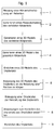
- the method for producing a patient-specific implant according to Fig. 1 includes the method steps described in more detail below.
- a violation of a body part of a patient is measured by means of an imaging method.
- a measurement data record is generated, which corresponds to a multi-dimensional image of the injury of the body part which has been determined with the imaging method.
- a measurement data set is generated in step 2, which serves the image data for creating a multi-dimensional model of the violation of the body part determined by the imaging method.
- a multi-dimensional model of the injured body part is generated from the measurement data record.
- a three-dimensional model can be generated with the measurement data set, which shows in particular the injury of the body part.
- the data set corresponding to a body part injured in a multi-dimensional image may be transformed by an algorithm into the multi-dimensional digital model of the injured body part.
- a multi-dimensional model of the healthy body part is generated with the aid of the multidimensional model of the injured body part.
- a three-dimensional model of the healthy body part is created.
- the multidimensional model of the healthy body part makes it possible, in a fifth step 5, to make a model of the Design implant. In doing so, the project staff can make adjustments to the body part that has been injured in the multi-dimensional model, which are important for the treatment of the injured body part.
- the multi-dimensional model of the implant can be adapted in a sixth step 6 to the load of the healthy body part, or to dimensions that are typically used in the intended defect area, so that a modified multi-dimensional model of the implant is obtained.
- An example for the generation of a modified multi-dimensional model of the implant is in Fig. 3 shown.
- a seventh step 7 the modified multi-dimensional model of the implant is converted into a print file for additive manufacturing process.
- a printer file may be generated containing a plurality of instructions for controlling an additive manufacturing process.
- instructions for the layered production of the implant by an additive manufacturing method in an additive manufacturing device will be created from the print file. From the printer file, for example, the guidance of the laser beam or electron beam and the number of layers to be printed in the additive manufacturing process are determined.
- the implant is manufactured in the additive manufacturing device.
- the implant in the additive manufacturing device is produced in layers according to the instructions for producing the implant provided in the print file for the additive manufacturing process.
- the implant is produced in particular in layers in the sintering process or melting process.
- the system for producing a patient-specific implant according to Fig. 2 includes the following system components, although the description should not exclude that further system components or components can be included in the system.
- a system component may be a building block or module that is part of the system.
- Fig. 2 extends over two sides, with the first part of the Fig. 2 With Fig. 2 (1) and the second part of the Fig. 2 With Fig. 2 (2) is called.
- An initialization unit 10 serves as a first system component for initiating the production of a patient-specific implant.
- a project is first created in a project database.
- a project employee opens the project database in a first step by contacting the project manager Log on project database. Authentication usually takes place via authentication by entering a user name and entering a password. A check is made as to whether the project member is already registered as a user of the database, that is, enjoys the status of a registered user. As a registered user, the project member also has access to all project data created by him at an earlier time.
- the project staff can generate a new project, create new patient data, or assign existing patients to a new project.
- the project is provided with a unique project number or project identifier. From this point on, the project employee can assign patient data to the project so that the project can be uniquely identified by the system based on this project master data. The project employee can also modify or supplement existing project master data.
- Such patient data may include image data as generated by an imaging process.
- the patient data may be measurement data that has been measured on the patient.
- These measurement data may include computed tomography (CT) data, for example.
- CT computed tomography
- the measurement data can be transferred into the database by means of a data carrier so that a measurement data record can be generated by means of a measurement data generation unit 20.
- a data carrier for example, a CD or DVD or a USB stick can be used, the data can also be procured or transferred over a network.
- a model generation module 30 creates a multi-dimensional model of the injured body part.
- the model generation module 30 utilizes the image data of the measurement data set and generates a multi-dimensional model of the body part or a plurality of body part segments of the injured body part.
- the body part is usually constructed using a conventional imaging measurement method of the plurality of body part segments, so that the multi-dimensional model results from the evaluation of the image data of the body part segments of the injured body part.
- the project operator can change the multi-dimensional model of the injured body part by automatically or manually positioning the body part or individual body part segments or changing their position relative to each other.
- an implant selection module 50 the project employee selects a model from an implant database or he creates a multi-dimensional model of an implant by means of an implant generation module 60.
- Each of the implant selection modules or Implant generation modules may enable the manipulation of cutting or slicing, shifting or rotation in the perspective of the viewer of the screen in the respective 2D image plane.
- the 2D image layer is formed by the screen so that the project team member can determine the best possible solution for a patient-specific implant by interacting with the models displayed on the screen.
- the model generation module 30 represents a multi-dimensional model of the injured body part and its spatial arrangement on the screen as a two-dimensional image of the three-dimensional arrangement of the body part or the body part segments.
- the multi-dimensional model shows in particular the structure of the injured body part. Due to the visualization of the multi-dimensional model on the screen, the project team member can decide if he wants to manipulate the multi-dimensional model.
- a model comparison module 40 may serve to create a multi-dimensional model of the healthy body part.
- This model comparison module can according to Fig. 2 have the same steps as the model generation module. Therefore, the model generation module is shown as an optional branch following modeling by the model generation module 30.
- the possible work steps for the creation of a multi-dimensional model of the healthy body part by means of the model comparison module 40 correspond to the work steps for creating a multi-dimensional model of the injured body part by means of the model generation module 30.
- the implant selection module 50 or the implant generation module 60 is used to create a multi-dimensional model of an implant, which is specially adapted to the multi-dimensional model of the injured or possibly the healthy body part.
- the implant selection module 50 utilizes a library of commercially available implants from which the project operator selects a suitable implant.
- the multi-dimensional model of the implant is placed by the project collaborator at the site of the multi-dimensional model of the injured or possibly healthy part of the body where it is needed to heal the injured body part.
- the project operator may place the model of the implant by displacement or rotational movement at the location of the multi-dimensional model of the body part which is damaged or weakened by the injury.
- the project staff member may at this point be responsible for the Fig. 3 perform the steps described.
- the Placement and positioning of fixation elements are used to attach the implant to the body part or body part segment.
- the positioning of the fixing elements can be made before the creation of the implant forming connecting elements.
- the connection elements are automatically generated as a multi-dimensional model so that the connection elements form a multi-dimensional model of the implant.
- the automatic generation of the multi-dimensional model of the connecting elements comprises the measurement of the distances and the angles between the fixing elements, the creation of holes for receiving the fixing elements, the calculation of the length, width and wall thickness of each connecting element and optionally a node element as a function of the on the body part acting loads.
- the stresses which act on the body part are determined, for example, on the basis of the density distribution of the tissue of the body part, for example the bone density distribution of the multi-dimensional model of the injured bone.
- the bone density distribution provides indications of the stress distribution in the bone. It can be used as a boundary condition in a finite element model of the implant, so that the optimal configuration can be determined by means of the finite element model of the implant.
- the result of the finite element model can be adjusted manually by means of the multi-dimensional model of the body part by the project staff, whereby in particular additional connecting elements can be provided or unused connecting elements can be removed.
- the wall thickness of the implant can be adapted to the installation situation.
- the bone density distribution can be color-coded on the surface or inside the multidimensional model of the bone.
- Each bone density is assigned a color when visualized in the model projection, so that the arrangement of the fixing elements can be easily checked manually.
- the fixation elements can be determined by the visualization on the multi-dimensional model of the body part.
- the orientation and length of the fixation elements can be determined automatically by calculation or manually set by the project staff.
- the fixing elements are an embodiment of modular elements according to FIG. 3 ,
- the system component may include a visualization in which the three-dimensional model is displayed as a transparent structure. In this visualization, it is possible to represent the volume and dimensions of the body part.
- the body part volume may have a tissue density distribution, or a bone density distribution, such that the length, diameter, or orientation of the fixation element may be manually adjusted based on the visualization of the body part volume.
- the spatial position of, for example, nerves, teeth, tendons or other structures relevant to the definition of the multi-dimensional implant, for example tissue structures can be represented on the basis of the visualization of the body part volume.
- a control system containing a control unit whether the model variant of the implant, its fasteners or its fixing elements are within the maximum allowable loads. If the control system detects that the limit has been exceeded, a warning or visual or audible warning will be generated to alert the project team member that the multi-dimensional model of the implant is failing to comply with one or more limits.
- a print file creation module 70 receives the modified multi-dimensional model of the implant from the implant selection module 50 or from the implant generation module 60.
- the print file creation module 70 converts the modified multi-dimensional model of the implant into a print file for an additive manufacturing process.
- an instruction generation module 80 By means of an instruction generation module 80, instructions for the layer-by-layer production of the implant by an additive manufacturing method in an additive manufacturing device 90 are created from the print file. The manufacture of the implant takes place in the additive manufacturing device.
- Fig. 3 shows the steps for creating a modified multi-dimensional implant model, which can be created by means of the implant selection module 50 or the implant generation module 60.
- the implant selection module allows the project staff to select their implant from a library of implants. For the implants stored in the library, an associated load profile is also stored. Depending on the material used for the implant this can withstand a different continuous load and can be selected to match the multi-dimensional model of the body part.
- Such an implant can be designed as a standard module as a module element 100.
- Fig. 3 schematically shows a greatly simplified representation of such modular elements 100, 110, 120, 130 and a plurality of fixing elements 140, 141, 142, 143, 144.
- a modified multi-dimensional implant model can also be constructed from a plurality of modular elements.
- a modified multi-dimensional implant model which consists of five module elements 100, as well as a module element 120, which comprises a branching element and a module element 130, which has an L-shape.
- These module elements are adapted to each other by the project staff.
- the module elements have at least one edge length in common with another module element.
- the load on the common edge length of two adjacent module elements is identical, otherwise a selection of the corresponding module element is not possible. That is, the edge length is a separation due to the shape of the module element that is no longer visible in the modified multi-dimensional implant model because the implant to be made from the modified multi-dimensional implant model is fabricated as a single contiguous component.
- Each of the edge lengths is assigned a load condition.
- the strength of the module element is selected to be at least equal to the strength at a maximum load of the body part, so that the load maximally exposed to the implant in use over its entire life is less than the fatigue strength of the module element.
- the invention is not limited to the present embodiments.
- the method steps can be used in particular for any implants for any body parts or limbs.
- the implants may be made of the materials mentioned or of a combination of the materials mentioned.
Abstract
1. Ein Verfahren zur Bereitstellung eines patientenspezifischen Implantats wird in mehreren Schritten mit einem System in weitgehend automatisierter Form durchgeführt. Eine Verletzung eines Körperteils eines Patienten wird mittels eines bildgebenden Verfahrens gemessen, ein Messdatensatz des verletzten Körperteils erzeugt, der einem mehrdimensionalen Abbild der Verletzung des Körperteils entspricht, die mit dem bildgebenden Verfahren ermittelt worden ist. Aus dem Messdatensatz wird ein mehrdimensionales Modell des verletzten Körperteils erzeugt, wobei mit Hilfe des mehrdimensionalen Modells des verletzten Körperteils ein Modell des gesunden Körperteils erzeugt werden kann, welches insbesondere die Kräfte enthält, welche durch eine Dauerbelastung auf das Körperteil wirken. Ein mehrdimensionales Modell des Implantats wird erstellt, welches an das mehrdimensionale Modell des Körperteils angepasst wird, sodass ein modifiziertes mehrdimensionales Modell des Implantats erhalten wird. Das modifizierte mehrdimensionale Modell des Implantats wird aus mindestens einem Modulelement generiert. Die Festigkeit des Modulelements wird so ausgewählt, dass sie mindestens der Festigkeit bei einer maximalen Belastung des Körperteils entspricht, sodass die Belastung, der das Implantat im Gebrauchszustand über seine gesamte Lebensdauer maximal ausgesetzt ist, kleiner als die Dauerfestigkeit des Modulelements ist.1. A method for providing a patient-specific implant is performed in several steps with a system in a largely automated form. A violation of a body part of a patient is measured by means of an imaging method, a measurement data record of the injured body part is generated, which corresponds to a multi-dimensional image of the injury of the body part which has been determined by the imaging method. From the measurement data set, a multidimensional model of the injured body part is generated, wherein a model of the healthy body part can be generated with the help of the multi-dimensional model of the injured body part, which contains in particular the forces acting on the body part by a continuous load. A multi-dimensional model of the implant is created, which is adapted to the multi-dimensional model of the body part, so that a modified multi-dimensional model of the implant is obtained. The modified multi-dimensional model of the implant is generated from at least one module element. The strength of the module element is selected to be at least equal to the strength at a maximum load of the body part, so that the load maximally exposed to the implant in use over its entire life is less than the fatigue strength of the module element.
Description
Die Erfindung betrifft ein Verfahren sowie ein System und ein Computerprogrammprodukt zur Herstellung eines Implantats, insbesondere zur Modellierung eines derartigen Implantats, welches beispielsweise mittels eines subtraktiven oder additiven Herstellungsverfahrens hergestellt werden kann. Bei dem Implantat handelt es sich um ein patientenspezifisches Implantat. Das Verfahren, das System sowie das Computerprogrammprodukt umfassen neben der eigentlichen Herstellung auch die vorgelagerten Schritte des Erstellens eines digitalen Modells des Implantats aufgrund von Patientendaten.The invention relates to a method and to a system and a computer program product for producing an implant, in particular for modeling such an implant, which can be produced for example by means of a subtractive or additive manufacturing method. The implant is a patient-specific implant. The method, the system and the computer program product include not only the actual production but also the upstream steps of creating a digital model of the implant based on patient data.
Aus dem Stand der Technik ist es bekannt, patientenspezifische Implantate mittels subtraktiven Verfahren, beispielsweise Bohren, Drehen, Fräsen herzustellen. Aus dem Stand der Technik ist aus der
Das Dokument
Es wurde auch in der
Es ist aus der
Aus der
Die Nutzung eines Computersystems mit einer Client-Server Struktur ist gemäss
Aus der
Die Formstabilität des Werkzeugs oder Führungselements wird gemäss
Daher ist es aufgrund der Verwendung des Werkzeugs oder Führungselements der
Für ein Implantat, welches eine tragende Funktion im Körper über einen möglichst langen Zeitraum ausüben können soll, ist aber die Kenntnis der im Implantat wirkenden Kräfte erforderlich, da hieraus beispielsweise das Ermüdungsbruchverhalten ermittelt werden kann. Dieses Ermüdungsbruchverhalten kann Hinweise über die natürliche biomechanische Belastung liefern, die während der gesamten Lebenserwartung eines Implantats im implantierten Zustand auftritt.For an implant, which should be able to perform a supporting function in the body over as long a period as possible, but the knowledge of the forces acting in the implant is required, since from this example, the fatigue failure behavior can be determined. This fatigue behavior can be evidence of the natural biomechanical Deliver stress that occurs throughout the life expectancy of an implant in the implanted state.
Aufgabe der Erfindung ist es, ein Verfahren sowie ein System zur Bereitstellung eines beliebig geformten Implantats vorzuschlagen, mittels welchem die Wartezeiten erheblich verringert werden können, weil das Implantat von einem Projektmitarbeiter nach Erhalt eines Messdatensatzes in einem zusammenhängenden Arbeitsablauf entworfen und hergestellt werden kann. Insbesondere wird das Verfahren und System derart vereinfacht, dass der Arzt unmittelbar nach Stellen der Diagnose mit den bei der Diagnose generierten Informationen bzw. Daten in die Lage versetzt wird, das Implantat zu entwerfen und dessen Herstellung in Auftrag zu geben.The object of the invention is to propose a method and a system for providing an arbitrarily shaped implant, by means of which the waiting times can be significantly reduced because the implant can be designed and manufactured by a project employee after receiving a measurement data set in a coherent workflow. In particular, the method and system are simplified in such a way that, immediately after the diagnosis has been made, the physician is enabled, with the information or data generated during the diagnosis, to design the implant and commission its manufacture.
Eine weitere Aufgabe der Erfindung ist es, eine Vorrichtung sowie ein Verfahren zur Herstellung eines beliebig geformten Implantats vorzuschlagen, bei dessen Auslegung die im Implantat während dessen bestimmungsgemässer Verwendung wirkenden Kräfte, Spannungen sowie Belastungszustände berücksichtigt werden können.Another object of the invention is to propose an apparatus and a method for producing an arbitrarily shaped implant, in the design of which the forces, stresses and load conditions acting in the implant during its intended use can be taken into account.
Zur Lösung dieser Aufgabe wird ein Baukastensystem vorgeschlagen, aus welchem der Projektmitarbeiter das für die gewünschte Verwendung optimale Implantat auswählen kann. Dieses Implantat kann vom Projektmitarbeiter in einem zusammenhängenden Arbeitsablauf entworfen und unter Berücksichtigung der Langzeitbelastung im Körper hergestellt werden.To solve this problem, a modular system is proposed from which the project staff can select the optimal for the desired use implant. This implant can be designed by the project collaborator in a coherent workflow and manufactured taking into account the long-term stress in the body.
Die Aufgabe der Erfindung wird durch ein Verfahren gemäss Anspruch 1 gelöst. Vorteilhafte Ausführungsbeispiele des Verfahrens sind Gegenstand der abhängigen Ansprüche 2 bis 7. Ein System zur Herstellung eines Implantats ist Gegenstand der Ansprüche 8 bis 15.The object of the invention is achieved by a method according to
Wenn der Begriff "beispielsweise" in der nachfolgenden Beschreibung verwendet wird, bezieht sich dieser Begriff auf Ausführungsbeispiele und/oder Ausführungsformen, was nicht notwendigerweise als eine bevorzugtere Anwendung der Lehre der Erfindung zu verstehen ist. In ähnlicher Weise sind die Begriffe "vorzugsweise", "bevorzugt" zu verstehen, indem sie sich auf ein Beispiel aus einer Menge von Ausführungsbeispielen und/oder Ausführungsformen beziehen, was nicht notwendigerweise als eine bevorzugte Anwendung der Lehre der Erfindung zu verstehen ist. Dementsprechend können sich die Begriffe "beispielsweise", "vorzugsweise" oder "bevorzugt" auf eine Mehrzahl von Ausführungsbeispielen und/oder Ausführungsformen beziehen.When the term "for example" is used in the following description, this term refers to embodiments and / or embodiments, which is not necessarily to be understood as a more preferred application of the teachings of the invention. Similarly, the terms "preferred," "preferred," are understood to refer to an example of a variety of embodiments and / or embodiments, which is not necessarily to be understood as a preferred application of the teachings of the invention. Accordingly, the terms "for example," "preferred," or "preferred," may refer to a plurality of embodiments and / or embodiments.
Die nachfolgende detaillierte Beschreibung enthält verschiedene Ausführungsbeispiele für das erfindungsgemässe Verfahren sowie das zugehörige System und Computerprodukt. Das Verfahren kann mittels unterschiedlicher Software ausgeführt werden, das System kann mittels unterschiedlicher Software betrieben werden sowie das Computerprogrammprodukt kann unterschiedliche Software enthalten, das sodass die Beschreibung einer bestimmten Software nur als beispielhaft anzusehen ist. In der Beschreibung und den Ansprüchen werden die Begriffe "enthalten", "umfassen", "aufweisen" als "enthalten, aber nicht beschränkt auf.." interpretiert.The following detailed description contains various embodiments of the inventive method and the associated system and computer product. The Method can be performed by means of different software, the system can be operated by means of different software and the computer program product may contain different software, so that the description of a particular software is to be regarded as exemplary only. In the specification and claims, the terms "including,""comprising,""having" are interpreted as "including but not limited to."
Die Aufgabe der Erfindung wird durch ein Verfahren zur Herstellung eines patientenspezifischen Implantats gelöst, wobei in einem ersten Schritt eine Verletzung eines Körperteils eines Patienten mittels eines bildgebenden Verfahrens gemessen wird. In einem zweiten Schritt wird ein Messdatensatz erzeugt, der einem mehrdimensionalen Abbild der Verletzung des Körperteils entspricht, der mit dem bildgebenden Verfahren ermittelt worden ist. In einem dritten Schritt wird aus dem Messdatensatz ein mehrdimensionales Modell der Verletzung des Körperteils erzeugt. In einem vierten Schritt wird mit Hilfe des mehrdimensionalen Modells der Verletzung des Körperteils ein Modell des gesunden Körperteils erzeugt, wobei eine Spiegelung des Abbilds des gesunden Körperteils in das Abbild des verletzten Körperteils erfolgen kann. In einem fünften Schritt wird ein mehrdimensionales Modell des Implantats erstellt. In einem sechsten Schritt wird das mehrdimensionale Modell des Implantats an das mehrdimensionale Modell des verletzten oder gesunden Körperteils angepasst, sodass ein modifiziertes mehrdimensionales Modell des Implantats erhalten wird. Gegebenenfalls wird das mehrdimensionale Modell des Implantats in einem oder mehreren Iterationsschritten aufgrund einer Berechnung der Belastung des Körperteils derart verändert, dass das mehrdimensionale Modell des Implantats den Belastungen des Körperteils bestmöglich standhält und/oder die Befestigung des Implantats am Körperteil eine minimale Abnützung des Körperteils zur Folge hat. In einem siebenten Schritt wird das modifizierte mehrdimensionale Modell des Implantats in eine Druckdatei für additives Herstellungsverfahren umgewandelt. Insbesondere kann die Druckdatei für den Betrieb in einer additiven Herstellungsvorrichtung verwendet werden. Die Druckdatei kann Anweisungen zur schichtweisen Erzeugung des Implantats enthalten. In einem achten Schritt werden aus der Druckdatei Anweisungen zur schichtweisen Herstellung des Implantats durch ein additives Herstellungsverfahren in einer additiven Herstellungsvorrichtung erstellt. In einem neunten Schritt wird das Implantat in der additiven Herstellungsvorrichtung hergestellt. Insbesondere kann das Implantat schichtweise gemäss den in der Druckdatei für das additive Herstellungsverfahren bereitgestellten Anweisungen zur Herstellung des Implantats hergestellt werden. Im fünften Schritt wird mit einem Implantatauswahlmodul ein mehrdimensionales Modell eines Implantats ausgewählt oder im sechsten Schritt ein mehrdimensionales Modell eines Implantats mit einem Implantatgenerierungsmodul erzeugt, wobei das mehrdimensionale Modell des Implantats an das mehrdimensionale Modell des verletzten oder gesunden Körperteils angepasst wird, sodass das modifizierte mehrdimensionale Modell des Implantats erhalten wird. Sämtliche Schritte können hierbei an einem Arbeitsplatz von einer Person ausgeführt werden. Daher ist es möglich, dass der Arzt bereits im Anschluss an die Diagnose selbst aus dem Messdatensatz das mehrdimensionale Modell des Implantats erstellt sowie das Modell modifiziert, sodass das modifizierte mehrdimensionale Modell des Implantats erhalten wird. Insbesondere kann das mehrdimensionale Modell des Implantats mit einer für die Modellierung zum Einsatz kommenden Software für die relevante mechanische Belastung im Einsatz ausgelegt werden. Die Software enthält integrierte Designrichtlinien um Stabilität und Herstellbarkeit des Implantats zu garantieren, welches das Ergebnis der Modellierung darstellt. Parameterkombinationen, welche zu einem instabilen oder nicht herstellbaren Implantat führen würden, werden von der Software verhindert. Daher muss sich der
Nach einem Ausführungsbeispiel kann zumindest eines der mehrdimensionalen Modelle des verletzten Körperteils, des gesunden Körperteils oder des Implantats in der Perspektive des Betrachters in einer zweidimensionalen Bildebene manipuliert werden. Insbesondere kann die Manipulation ein Durchtrennen oder Schneiden, ein Verschieben oder ein Rotieren zumindest eines der mehrdimensionalen Modelle des verletzten Körperteils, des gesunden Körperteils oder des Implantats umfassen.The object of the invention is achieved by a method for producing a patient-specific implant, wherein in a first step an injury of a body part of a patient is measured by means of an imaging method. In a second step, a measurement data record is generated that corresponds to a multi-dimensional image of the injury of the body part that was determined using the imaging method. In a third step, a multi-dimensional model of the injury of the body part is generated from the measurement data record. In a fourth step, a model of the healthy body part is generated with the aid of the multidimensional model of the injury of the body part, wherein a reflection of the image of the healthy body part into the image of the injured body part can take place. In a fifth step, a multi-dimensional model of the implant is created. In a sixth step, the multi-dimensional model of the implant is adapted to the multi-dimensional model of the injured or healthy body part, so that a modified multi-dimensional model of the implant is obtained. Optionally, the multi-dimensional model of the implant is changed in one or more iteration steps due to a calculation of the load of the body part such that the multi-dimensional model of the implant can best withstand the stresses of the body part and / or attachment of the implant to the body part results in minimal wear of the body part Has. In a seventh step, the modified multi-dimensional model of the implant is converted into a print file for additive manufacturing processes. In particular, the print file may be used for operation in an additive manufacturing device. The print file may contain instructions for layering the implant. In an eighth step, instructions are made from the print file for layering the implant by an additive manufacturing process in an additive manufacturing device. In a ninth step, the implant is manufactured in the additive manufacturing device. In particular, the implant can be produced in layers according to the instructions for producing the implant provided in the print file for the additive manufacturing method. The fifth step is with a The implant selection module selects a multi-dimensional model of an implant or in the sixth step generates a multi-dimensional model of an implant with an implant generation module, the multi-dimensional model of the implant is adapted to the multi-dimensional model of the injured or healthy body part, so that the modified multi-dimensional model of the implant is obtained. All steps can be carried out by one person at one workstation. Therefore, it is possible for the physician to create the multidimensional model of the implant from the measured data set as well as to modify the model after the diagnosis itself so that the modified multi-dimensional model of the implant is obtained. In particular, the multi-dimensional model of the implant can be designed with a software used for the modeling for the relevant mechanical load in use. The software contains integrated design guidelines to guarantee stability and manufacturability of the implant, which is the result of the modeling. Parameter combinations that would lead to an instable or non-manufacturable implant are prevented by the software. Therefore, the must
According to one embodiment, at least one of the multi-dimensional models of the injured body part, the healthy body part or the implant can be manipulated in the perspective of the observer in a two-dimensional image plane. In particular, the manipulation may include severing or cutting, displacing or rotating at least one of the multi-dimensional models of the injured body part, the healthy body part or the implant.
Im zweiten Schritt kann das Messergebnis nach Erzeugen eines Projekts in einer Initialisierungseinheit in eine Messdatengenerierungseinheit eingespeist werden, wobei ein Messdatensatz erzeugt wird, der einem mehrdimensionalen Abbild der Verletzung des Körperteils entspricht, die mit dem bildgebenden Verfahren ermittelt worden ist.In the second step, after generating a project in an initialization unit, the measurement result can be fed into a measurement data generation unit, wherein a measurement data record corresponding to a multi-dimensional image of the injury of the body part determined with the imaging method is generated.
Im dritten Schritt kann aus dem Messdatensatz ein mehrdimensionales Modell des verletzten Körperteils in einem Modellgenerierungsmodul erzeugt werden.In the third step, a multi-dimensional model of the injured body part in a model generation module can be generated from the measurement data record.
Im vierten Schritt kann mit Hilfe des mehrdimensionalen Modells des verletzten Körperteils ein Modell des gesunden Körperteils in einem Modellvergleichsmodul erzeugt werden.In the fourth step, a model of the healthy body part in a model comparison module can be generated with the aid of the multidimensional model of the injured body part.
Nach einem Ausführungsbeispiel kann das mehrdimensionale Modell des Implantats an die Belastungsverhältnisse, denen der gesunde Körperteil ausgesetzt ist, angepasst werden.According to one embodiment, the multi-dimensional model of the implant may be adapted to the loading conditions to which the healthy body part is exposed.
Insbesondere kann das modifizierte mehrdimensionale Modell des Implantats Hohlräume oder poröse Abschnitte enthalten, welche das Verwachsen des Implantats mit dem umliegenden Gewebe fördern.In particular, the modified multi-dimensional model of the implant may include voids or porous sections that promote ingrowth of the implant to the surrounding tissue.
Nach einem Ausführungsbeispiel entsprechen die Abmessungen des Implantats den Abmessungen eines durch die Verletzung des Körperteils entstandenen Hohlraums, sodass das Implantat zumindest ein Volumen einnimmt, welches dem Volumen des Hohlraums entspricht.According to one embodiment, the dimensions of the implant correspond to the dimensions of a cavity created by the injury of the body part, so that the implant occupies at least one volume which corresponds to the volume of the cavity.
Insbesondere kann das additive Herstellungsverfahren ein Lasersinterverfahren oder ein Laserschmelzverfahren oder ein Elektronenstrahlschmelzverfahren (EBM) umfassen. Ebenso können Extrusionsverfahren oder 3D Druckverfahren zur Anwendung kommen, welche auch als Binder in Bett Verfahren bekannt sind. Der Rohstoff für das Implantat kann zumindest ein Element aus der Gruppe der Metalle, der keramischen Materialien oder der Kunststoffe umfassen. Insbesondere kann der Rohstoff für das Implantat Titan enthalten. Der Rohstoff für das Implantat kann pulverförmig, flüssig oder als Filament vorliegend sein.In particular, the additive manufacturing method may include a laser sintering method or a laser melting method or an electron beam melting method (EBM). Likewise, extrusion processes or 3D printing processes can be used, which are also known as binder in bed processes. The raw material for the implant may comprise at least one element from the group of metals, ceramic materials or plastics. In particular, the raw material for the implant may contain titanium. The raw material for the implant may be powdery, liquid or present as a filament.
Nach einem Ausführungsbeispiel kann der Messdatensatz, der einem mehrdimensionalen Abbild der Verletzung des Körperteils entspricht, durch einen Algorithmus in das mehrdimensionale Modell der Verletzung des Körperteils transformiert werden. Nach einem Ausführungsbeispiel kann das mehrdimensionale Modell der Verletzung des Körperteils durch einen Algorithmus in das mehrdimensionale Modell des gesunden Körperteils transformiert werden. Insbesondere kann ein Messdatensatz eines gesunden Körperteils des Patienten generiert werden. Diese Vorgehensweise eignet sich insbesondere dann, wenn es sich bei dem verletzten Körperteil um einen Körperteil handelt, für den ein spiegelbildlich angeordneter Körperteil im oder am Körper des Patienten vorhanden ist, beispielsweise ein Bestandteil des Kopfs, Extremitäten, insbesondere ein Bestandteil der Arme oder Beine. Ein derartiger Körperteil wird in der Folge als chirale Modifikation des verletzten Körperteils bezeichnet, wobei unter chiraler Modifikation eine im Spiegelbild deckungsgleiche Anordnung zu verstehen ist. Eine linke Hand ist beispielsweise eine chirale Modifikation einer rechten Hand. Wenn ein Körperteil von der Verletzung betroffen ist, von welchem eine chirale Modifikation im oder am Körper existiert, kann dieser Körperteil durch eine Spiegelung in ein Abbild des verletzten Körperteils im unverletzten Zustand, also im gesunden Zustand, überführt werden. Nach diesem Ausführungsbeispiel liegen dem Projektmitarbeiter ein mehrdimensionales Modell des verletzten Körperteils sowie ein mehrdimensionales Modell des gesunden Körperteils vor, der durch Spiegelung seiner chiralen Modifikation erhalten worden ist. Das heisst, der Projektmitarbeiter kann eine Visualisierung des verletzten Körperteils und eine Visualisierung des gesunden Körperteils vornehmen.According to one embodiment, the measurement data set, which corresponds to a multi-dimensional image of the injury of the body part, can be transformed by an algorithm into the multi-dimensional model of the injury of the body part. According to one embodiment, the multi-dimensional model of injury to the body part may be transformed by an algorithm into the multi-dimensional model of the healthy body part. In particular, a measurement data set of a healthy body part of the patient can be generated. This procedure is particularly suitable when the injured body part is a body part for which a mirror-inverted body part is present in or on the patient's body, for example a component of the head, extremities, in particular a component of the arms or legs. Such a body part is referred to in the following as a chiral modification of the injured body part, whereby a chiral modification is to be understood as a congruent arrangement in the mirror image. For example, a left hand is a chiral modification of a right hand. If a body part is affected by the injury, of which a chiral modification exists in or on the body, this body part can be converted by reflection into an image of the injured body part in the uninjured state, ie in the healthy state. According to this embodiment, the project collaborator has a multi-dimensional model of the injured body part and a multi-dimensional model of the healthy body part obtained by mirroring its chiral modification has been. This means that the project staff can visualize the injured body part and visualize the healthy body part.
Nach einem Ausführungsbeispiel kann im siebenten Schritt das modifizierte mehrdimensionale Modell des Implantats mittels eines Druckdateierstellungsmoduls in eine Druckdatei für ein additives Herstellungsverfahren umgewandelt werden. Insbesondere können dabei bestehende Standardformate für additive Herstellungsverfahren wie STL, 3MF oder AMF ausgelassen werden und direkt die additiven Herstellungsverfahren angesteuert werden. Dabei werden die spezifischen Prozessführungsparameter der additiven Herstellungsverfahren direkt im Druckdateierstellungsmodul definiert und als lesbare Datei an die Steuerung des additiven Herstellungsverfahrens übergeben.In one embodiment, in the seventh step, the modified multi-dimensional model of the implant may be converted to a print file for an additive manufacturing process by a print file creation module. In particular, existing standard formats for additive manufacturing processes such as STL, 3MF or AMF can be omitted and the additive manufacturing processes can be controlled directly. The specific process control parameters of the additive manufacturing process are defined directly in the print file creation module and transferred as a readable file to the controller of the additive manufacturing process.
Nach einem Ausführungsbeispiel kann im achten Schritt mittels eines Anweisungsgenerierungsmoduls aus der Druckdatei Anweisungen zur schichtweisen Herstellung des Implantats durch ein additives Herstellungsverfahren in der additiven Herstellungsvorrichtung erstellt werden. Die Herstellung kann an der Klinik selber oder bei einem kliniknahen Dienstleister erfolgen.According to one embodiment, in the eighth step, instructions for producing the implant in layers by an additive manufacturing method in the additive manufacturing apparatus can be created by means of an instruction generation module from the print file. Production can take place at the clinic itself or at a clinic-related service provider.
Nach einem Ausführungsbeispiel kann die Druckdatei für das additive Herstellungsverfahren einer additiven Herstellungsvorrichtung über ein Netzwerk, beispielsweise unter Nutzung des Internets an die additive Herstellungsvorrichtung übermittelt werden.According to an exemplary embodiment, the print file for the additive manufacturing method of an additive manufacturing device can be transmitted to the additive manufacturing device via a network, for example using the internet.
Nach einem Ausführungsbeispiel kann das bildgebende Verfahren zumindest ein Verfahren aus der Gruppe der Röntgenverfahren, MRI-Verfahren, CT-Verfahren, Ultraschallverfahren, optischen Scanverfahren oder Laserscanverfahren umfassen.According to one exemplary embodiment, the imaging method may include at least one of X-ray methods, MRI methods, CT methods, ultrasound methods, optical scanning methods or laser scanning methods.
Ein System zur Herstellung eines Implantats umfasst eine Initialisierungseinheit zur Erzeugung eines Projekts. Das System umfasst eine Messdatengenerierungseinheit, mittels welcher ein Messdatensatz aus einer Messung am Patienten mittels eines bildgebenden Verfahrens generierbar ist, wobei der Messdatensatz ein Abbild eines verletzten Körperteils enthält, welches mittels eines bildgebenden Messverfahrens erstellt ist. Das System umfasst des Weiteren ein Modellgenerierungsmodul, mittels welchem ein mehrdimensionales Modell des verletzten Knoches aus dem Messdatensatz generierbar ist. Gegebenenfalls ist ein Modellvergleichsmodul vorgesehen, mittels welchem ein mehrdimensionales Modell eines gesunden Körperteils generierbar ist. Mittels einem Implantatauswahlmodul kann ein Implantat aus einer Bibliothek von Implantatmodellen derart auswählbar sein, dass das Implantatmodell mittels des Modellgenerierungsmoduls oder des Modellvergleichsmoduls an das mehrdimensionale Modell des verletzten oder gesunden Körperteils anpassbar ist und/oder mittels einem Implantatgenerierungsmodul, mittels welchem ein mehrdimensionales Modell eines Implantats derart erzeugbar ist, dass ein für die spezifische Verletzung neu entwickeltes mehrdimensionales Implantatmodell generierbar ist, sodass mit zumindest einem der Implantatauswahlmodule oder Implantatgenerierungsmodule ein modifiziertes mehrdimensionales Modell des Implantats erhältlich ist. Das Implantatmodell kann in ein Druckdateierstellungsmodul für ein additives Herstellungsverfahren aufnehmbar sein. Ein Anweisungsgenerierungsmodul kann vorgesehen sein, mittels welchem eine vom Druckdateierstellungsmodul erstellte Druckdatei in eine Herstellungsanweisung für eine additive Herstellungsvorrichtung umwandelbar ist. Die additive Herstellungsvorrichtung ist vorgesehen, um das Implantat gemäss der Herstellungsanweisung zu erzeugen oder herzustellen. Aus dem modifizierten mehrdimensionalen Modell des Implantats ist mit zumindest einem der Implantatauswahlmodule oder Implantatgenerierungsmodule ein patientenspezifisches Implantat erhältlich.A system for manufacturing an implant includes an initialization unit for creating a project. The system comprises a measurement data generation unit, by means of which a measurement data set can be generated from a measurement on the patient by means of an imaging method, wherein the measurement data set contains an image of an injured body part, which is created by means of an imaging measurement method. The system further comprises a model generation module by means of which a multi-dimensional model of the injured bone can be generated from the measurement data record. Optionally, a model comparison module is provided, by means of which a multi-dimensional model of a healthy body part can be generated. By means of an implant selection module, an implant can be selected from a library of implant models in such a way that the implant model can be selected by means of the model generation module or the model comparison module the multidimensional model of the injured or healthy body part is adaptable and / or by means of an implant generation module, by means of which a multidimensional model of an implant can be generated in such a way that a multidimensional implant model newly developed for the specific injury can be generated, with at least one of the implant selection modules or implant generation modules modified multi-dimensional model of the implant is available. The implant model may be receivable in a print file creation module for an additive manufacturing process. An instruction generation module can be provided, by means of which a print file created by the print file creation module can be converted into a manufacturing instruction for an additive manufacturing device. The additive manufacturing device is provided to produce or manufacture the implant according to the manufacturing instruction. From the modified multi-dimensional model of the implant, a patient-specific implant is available with at least one of the implant selection modules or implant generation modules.
Nach einem Ausführungsbeispiel kann mittels dem Implantatauswahlmodul oder dem Implantatgenerierungsmodul zumindest eines der mehrdimensionalen Modelle des verletzten Körperteils, des gesunden Körperteils oder des Implantats in der Perspektive des Betrachters in einer zweidimensionalen Bildebene mittels eines Implantatbearbeitungsmoduls manipulierbar sein. Insbesondere kann das Implantatbearbeitungsmodul zumindest ein Element aus der Gruppe der Trennmodule, der Schneidmodule, der Verschiebemodule oder der Rotationsmodule enthalten.According to one exemplary embodiment, at least one of the multi-dimensional models of the injured body part, the healthy body part or the implant can be manipulated in the perspective of the observer in a two-dimensional image plane by means of an implant processing module by means of the implant selection module or the implant generation module. In particular, the implant processing module can contain at least one element from the group of separation modules, the cutting modules, the displacement modules or the rotation modules.
Nach einem Ausführungsbeispiel kann das mittels des Implantatauswahlmoduls ausgewählte Implantatmodell oder das mit dem Implantatgenerierungsmodul entwickelte Implantatmodell mittels eines Belastungsintensitätsmoduls auf das Vorhandensein von übermässigen Belastungen für den Körperteil überprüfbar sein.According to one exemplary embodiment, the implant model selected by means of the implant selection module or the implant model developed using the implant generation module can be verifiable by means of a load intensity module for the presence of excessive loads on the body part.
Insbesondere kann das mehrdimensionale Modell des Implantats vom Projektmitarbeiter aus dem mehrdimensionalen Modell der Verletzung des Körperteils oder des gesunden Körperteils erstellt werden. Bei Erstellung des Modells können Spannungszustände im Implantat über eine Finite-Elemente-Methode bestimmt werden. Beispielsweise kann der Gewebeaufbau in der Umgebung des Defekts Rückschlüsse über die örtliche Belastung des Gewebes an der Begrenzungsoberfläche des Defekts liefern. Diese örtliche Belastung muss durch das Implantat aufgenommen werden können.
Ein Belastungsprofil (also die Zugspannungen, Druckspannungen, Schubspannungen) des Körperteils, insbesondere des Knochens können aus der Knochendichte gemäss einem von Pal et al. aufgestellten empirischen Zusammenhang ermittelt werden. (siehe auch
Dieses Belastungsprofil des Körperteils, also insbesondere des Knochens kann als Randbedingung für die Erstellung des FEM-Modells des Implantats dienen, sodass das FEM-Modell das Belastungsprofil berücksichtigen kann. Die Dichte des Knochens kann aus dem Messdatensatz, welche das bildgebende Verfahren geliefert hat, für jeden Punkt der Begrenzungsoberfläche ermittelt werden. Daher ist unter Nutzung dieser Informationen aus dem bildgebenden Verfahren eine Modellgeometrie erhältlich, welche dieses Belastungsprofil berücksichtigt. Insbesondere kann das Belastungsprofil auch Rückschlüsse auf die dynamische Belastung des Knochens und in der Folge des Implantats liefern, sodass bei der Erstellung eines mehrdimensionalen Modells des Implantats ein dynamischer Belastungszustand berücksichtigt werden kann und Beschädigungen des Implantats oder des Knochens durch die dynamische Belastung vermieden werden können.This load profile of the body part, ie in particular of the bone can serve as a boundary condition for the creation of the FEM model of the implant, so that the FEM model can take into account the load profile. The density of the bone may be determined from the measurement data set provided by the imaging method for each point of the boundary surface. Therefore, using this information from the imaging process, a model geometry is available that takes into account this stress profile. In particular, the load profile can also provide conclusions about the dynamic loading of the bone and in the sequence of the implant, so that when creating a multi-dimensional model of the implant, a dynamic load condition can be considered and damage to the implant or the bone can be avoided by the dynamic load.
Das Verfahren oder System nach einem der vorhergehenden Ausführungsbeispiele kann zur Herstellung eines Implantats aus der Gruppe der Spinalimplantate, Dentalimplantate, orthopädischen Implantate, künstlichen Linsen, Knochenteile, Knorpeltele, Augenimplantate, Gelenkimplantate, kosmetische Implantate verwendet werden.The method or system according to one of the preceding embodiments can be used for producing an implant from the group of spinal implants, dental implants, orthopedic implants, artificial lenses, bone parts, cartilaginous gels, eye implants, joint implants, cosmetic implants.
Nach einem Ausführungsbeispiel kann das patientenspezifische Implantat innerhalb von einer Woche nach dem Start der Initialisierungseinheit erhältlich sein, insbesondere kann bei lokaler Verfügbarkeit der additiven Herstellungsvorrichtung ein patientenspezifisches Implantat innerhalb eines Zeitraums von maximal drei Tagen erhältlich sein.According to one exemplary embodiment, the patient-specific implant can be obtainable within one week after the start of the initialization unit; in particular, if the additive manufacturing device is locally available, a patient-specific implant can be available within a maximum period of three days.
Die Erstellung des mehrdimensionalen Modells und die Anpassung desselben durch den Projektmitarbeiter kann sehr einfach in wenigen Arbeitsschritten am Arbeitsplatz des Projektmitarbeiters vorgenommen werden. Der Projektmitarbeiter benötigt hierzu einen Rechner mit Internetzugang, ein Eingabeelement, einen Bildschirm zur Visualisierung des mehrdimensionalen Modells. Der Projektmitarbeiter kann sich mit einem handelsüblichen Browserprogramm Zugang zu einer Webseite verschaffen, welche die Modellierungssoftware zur Erstellung des mehrdimensionalen Modells des verletzten Körperteils aus dem Datensatz enthält. Die Software umfasst vorteilhafterweise auch Zugang zu einer Datenbank, welche die Verletzung eindeutig einem Patienten zuordnen kann. Der Projektmitarbeiter kann in einem ersten Schritt einen Patientendatensatz erzeugen. Nach Erstellung des Patientendatensatzes lädt der Projektmitarbeiter den Messdatensatz in die Datenbank aufgrund der Anweisungen, die ihm auf dem Bildschirm angezeigt werden. Der Messdatensatz ist eine Datei, die von der Vorrichtung zur Durchführung des bildgebenden Verfahrens erzeugt worden ist. Diese Datei kann von einem beliebigen Datenträger, beispielsweise von einer CD-ROM, einem USB-Stick oder dergleichen stammen. Die Datei kann insbesondere eine Bilddatendatei umfassen, beispielsweise eine bitmap - Datei, eine Portable Network Grafics (PNG) Datei, eine jpg-Datei, eine Datei, welche die Originaldaten des bildgebenden Verfahrens insbesondere gemäss des DICOM Standards enthält, oder ein PDF-Dokument umfassen. In Abhängigkeit von der Geschwindigkeit des Internetzugangs und der Grösse der Datei kann dieser Vorgang des Einlesens des Messdatensatzes in die Modellierungssoftware in weniger als 10 min abgeschlossen sein, wenn die Übertragungsgeschwindigkeit einige Mbit/sec beträgt.The creation of the multi-dimensional model and its adaptation by the project staff can very easily be done in a few steps at the workstation of the project member. The project team member requires one Computer with Internet access, an input element, a screen to visualize the multidimensional model. The project associate may use a standard browser program to gain access to a web page containing the modeling software for creating the multi-dimensional model of the injured body part from the dataset. The software advantageously also includes access to a database which can clearly assign the injury to a patient. The project employee can generate a patient record in a first step. After the patient record is created, the project associate loads the measurement record into the database based on the instructions that appear on the screen. The measurement data set is a file that has been generated by the device for carrying out the imaging method. This file can come from any disk, such as a CD-ROM, a USB stick or the like. The file may in particular comprise an image data file, for example a bitmap file, a Portable Network Grafics (PNG) file, a jpg file, a file containing the original data of the imaging method, in particular according to the DICOM standard, or a PDF document , Depending on the speed of the Internet access and the size of the file, this process of reading the measurement data set into the modeling software may be completed in less than 10 minutes if the transmission speed is a few Mbit / sec.
Nach dem Laden der Messdatendatei wird durch die Modellierungssoftware ein mehrdimensionales Modell des oder der verletzten Körperteile erstellt. Dieses mehrdimensionale Modell ist insbesondere als ein Oberflächenmodell ausgebildet, mittels welchem der verletzte Körperteil in der Lage angezeigt wird, welche der verletzte Körperteil bei Durchführung des bildgebenden Verfahrens hatte. Der Projektmitarbeiter findet somit auf dem Bildschirm die Ansicht vor, die der Ansicht entspricht, welche der verletzte Körperteil zum Zeitpunkt der Durchführung des bildgebenden Verfahrens gehabt hat.After loading the measurement data file, the modeling software creates a multi-dimensional model of the injured body part (s). In particular, this multi-dimensional model is designed as a surface model by means of which the injured body part is displayed in the position which the injured body part had when carrying out the imaging process. The project operator thus finds on the screen the view corresponding to the view which the injured body part had at the time of performing the imaging process.
Der Projektmitarbeiter kann die Lage des mehrdimensionalen Modells des Körperteils am Bildschirm derart verändern, dass ihm die gewünschte Ansicht am Bildschirm angezeigt wird. Der Projektmitarbeiter kann die Lage von Teilen des mehrdimensionalen Modells des Körperteils am Bildschirm derart verändern, dass sie in der gewünschten Lage zueinander liegen.The project operator can change the position of the multi-dimensional model of the body part on the screen so that the desired view is displayed on the screen. The project operator can change the location of parts of the multi-dimensional model of the body part on the screen so that they are in the desired position to each other.
Insbesondere kann der Projektmitarbeiter das mehrdimensionale Modell des Körperteils frei in jede beliebige Richtung drehen oder in jede beliebige Richtung verschieben. Hierzu wählt der Projektmitarbeiter mit einem Eingabeelement einen Punkt des mehrdimensionalen Modells aus. Das Eingabeelement kann ein akustisches Eingabeelement, beispielsweise ein Mikrophon, ein berührungssensitives Eingabeelement, beispielsweise einen Touchscreen, der gegebenenfalls eine Multitouchfunktion enthält, einen Joystick, ein Gamepad, ein Stift oder ein optisches Eingabeelement umfassen, beispielsweise einen Scanner, ein Stift mit Scanfunktion, oder ein Eingabeelement welches eine Kombination von mindestens zwei der akustischen, berührungssensitiven, optischen Eingabeelemente umfasst. Insbesondere kann mit dem Eingabeelement Gestik, beispielsweise Fingerbewegungen erfassbar und in Eingabeanweisungen umwandelbar sein. Der vom Eingabeelement ausgewählte Punkt ist im mehrdimensionalen Modell in Bezug auf jeden weiteren Punkt des mehrdimensionalen Modells festgelegt, da der Punkt zu jedem anderen Punkt des dreidimensionalen Modells einen eindeutig bestimmten Abstand sowie eine eindeutig bestimmte Raumrichtung aufweist. Das mehrdimensionale Modell kann hierbei aus einem dreidimensionalen Netz von Punkten bestehen. Durch Verbinden der Punkte mit Dreiecken kann die Oberfläche des Modells dargestellt werden Der ausgewählte Punkt kann vom Projektmitarbeiter mittels des Eingabeelements auf dem Bildschirm bewegt werden. Die Bewegung kann eine Verschiebung in Bezug auf einen Referenzpunkt sein, wobei der Referenzpunkt beispielsweise der Ursprung eines Koordinatensystems ist. Das mehrdimensionale Modell kann eine Mehrzahl von Modellfragmenten umfassen. Möchte der Projektmitarbeiter eines der Modellfragmente relativ zu einem anderen Modellfragment verschieben, wird zuerst durch die Lage des mehrdimensionalen Modells in Bezug auf die Bildschirmebene eine Betrachtungsperspektive erzeugt. Der Projektmitarbeiter sieht das mehrdimensionale Modell aus der Betrachterperspektive als Projektion auf die Bildschirmebene. Der Projektmitarbeiter kann ein Modellfragment relativ zu einem weiteren Modellfragment verschieben, indem er auf dem Bildschirm die Umrisse des zu verschiebenden Modellfragments auswählt und den gewünschten Abstand sowie die Richtung der Verschiebung, das heisst den Neigungswinkel in Bezug auf eine horizontale (oder vertikale) Bildschirmreferenzlinie festlegt.In particular, the project operator can freely rotate the multi-dimensional model of the body part in any direction or move in any direction. To do this select the project associate with an input element one point of the multi-dimensional model. The input element may include an acoustic input element, for example a microphone, a touch-sensitive input element, for example a touch screen, optionally containing a multi-touch function, a joystick, a game pad, a stylus or an optical input element, for example a scanner, a pen with a scan function, or a Input element comprising a combination of at least two of the acoustic, touch-sensitive, optical input elements. In particular, with the input element gestures, for example finger movements, can be detected and converted into input instructions. The point selected by the input element is defined in the multi-dimensional model with respect to each additional point of the multi-dimensional model, since the point to each other point of the three-dimensional model has a unique distance and a unique spatial direction. The multi-dimensional model can consist of a three-dimensional network of points. By connecting the points with triangles, the surface of the model can be displayed. The selected point can be moved by the project member using the input element on the screen. The movement may be a displacement with respect to a reference point, the reference point being, for example, the origin of a coordinate system. The multi-dimensional model may include a plurality of model fragments. If the project collaborator wants to move one of the model fragments relative to another model fragment, then the view of the multidimensional model with respect to the screen plane first creates a viewing perspective. The project collaborator sees the multidimensional model from the perspective of the viewer as a projection on the screen level. The project associate can move a model fragment relative to another model fragment by selecting on the screen the outlines of the model fragment to be moved and specifying the desired distance and direction of displacement, ie, the tilt angle relative to a horizontal (or vertical) screen reference line.
Die Bewegung kann eine Drehbewegung sein, wobei die Drehbewegung in Bezug auf eine Drehachse, die senkrecht zur Betrachtungsrichtung liegt, erfolgt. Das heisst, die Drehachse verläuft normal zur Bildschirmebene. Die Position der Drehachse kann der Projektmitarbeiter festlegen, indem er einen Punkt der gewünschten Drehachse auf dem Bildschirm auswählt. Die Position der Drehachse kann vom System auch automatisch ins Zentrum des Fragments gelegt werden, beispielsweise in den Masseschwerpunkt oder in das Zentrum eines umschliessenden Volumenkörpers. Den gewünschten Drehwinkel kann der Projektmitarbeiter durch Festlegen eines Drehwinkels auswählen.The movement may be a rotational movement, wherein the rotational movement with respect to an axis of rotation, which is perpendicular to the viewing direction, takes place. That is, the rotation axis is normal to the screen level. The position of the rotation axis can be set by the project employee by selecting a point of the desired rotation axis on the screen. The position of the axis of rotation can also be automatically placed by the system in the center of the fragment, for example in the center of mass or in the center of a enclosing volume body. The project operator can select the desired rotation angle by specifying a rotation angle.
Der Projektmitarbeiter kann auch einen Schnitt durch das mehrdimensionale Modell erzeugen, indem er eine Schnittebene definiert. Durch das Definieren der Schnittebene erfolgt ein Durchtrennen des mehrdimensionalen Modells entlang dieser Schnittebene. Die Schnittebene kann man sich als virtuelles Messer vorstellen, mittels welchem das mehrdimensionale Modell in Richtung der Betrachtungsperspektive durchtrennt wird. Das heisst, die Schnittebene liegt normal zur Bildschirmoberfläche. Der Projektmitarbeiter kann jede beliebige Schnittebene erzeugen, indem er zwei Punkte auf der Bildschirmoberfläche auswählt, welche die Schnittgerade der Schnittebene mit der Bildschirmoberfläche erzeugen. Alternativ kann der Projektmitarbeiter einen Punkt anwählen und auf dem Bildschirm mit dem Eingabeelement eine Strecke definieren, welche die Richtung der Schnittebene festlegt. Dabei bildet der Eingabepunkt, der mit dem Eingabeelement auf dem Bildschirm erzeugt wird, die Spitze des virtuellen Messers aus. Durch Bewegung des Eingabeelements wird eine Schnittlinie, bestehend aus mehreren kleinen Schnittlinien (-ebenen), definiert, die insbesondere eine horizontale oder vertikale Schnittlinie sein kann oder auch in einem beliebigen Neigungswinkel zu der horizontalen Schnittlinie angeordnet sein kann. Horizontal und vertikal bezieht sich hierbei auf die Position der Schnittlinie in der Bildschirmebene.The project collaborator can also create a section through the multidimensional model by defining a section plane. By defining the cutting plane, the multi-dimensional model is cut along this cutting plane. The cutting plane can be thought of as a virtual knife, by means of which the multidimensional model is severed in the direction of the viewing perspective. This means that the cutting plane is normal to the screen surface. The project operator can create any section plane by selecting two points on the screen surface that create the intersection line of the section plane with the screen surface. Alternatively, the project operator can select a point and define on the screen with the input element a distance that defines the direction of the cutting plane. The input point created with the input element on the screen forms the tip of the virtual knife. By movement of the input element, a cutting line, consisting of several small cutting lines (planes) defined, which may be in particular a horizontal or vertical cutting line or may be arranged at an arbitrary inclination angle to the horizontal cutting line. Horizontal and vertical refers to the position of the cut line in the screen plane.
Das mehrdimensionale Modell kann somit durch eine Verschiebung oder Drehung bzw. Rotation beliebig im Modellraum ausgerichtet werden, um dann durch eine benutzerdefinierte Schnittlinie durchtrennt zu werden.The multi-dimensional model can thus be arbitrarily aligned in the model space by a displacement or rotation or rotation, and then cut through a user-defined cutting line.
Die Manipulationen des Durchtrennens oder Schneidens, des Verschiebens oder des Rotierens erfolgen nur aus der Perspektive des Betrachters des Bildschirms in der jeweiligen 2D-Bild-Ebene, die durch den Bildschirm gebildet wird. Dadurch kann die Bedienkomplexität reduziert werden, sodass eine einfache und intuitive Manipulation von mehrdimensionalen Modellen ohne vorgängige Schulung möglich ist. Dieses Verfahren eignet sich aufgrund der Vereinfachung auch für die Ausführung auf Tablets.The manipulations of cutting or slicing, shifting or rotating are only from the perspective of the viewer of the screen in the respective 2D image plane formed by the screen. This reduces the complexity of the operation, allowing easy and intuitive manipulation of multi-dimensional models without prior training. This method is also suitable for use on tablets due to its simplicity.
Alternativ ist es möglich, mittels eines Positionierbefehls eine automatische Zuordnung der Oberflächen von Körperteilfragmenten zueinander zu erstellen und die Verbindungsflächen zwischen den neu positionierten Körperteilen oder Körperteilfragmenten zu erstellen.Alternatively, it is possible to automatically associate the surfaces of body part fragments with each other by means of a positioning command and to create the connection surfaces between the repositioned body parts or body part fragments.
Der Projektmitarbeiter kann anhand der visuellen Darstellung der Anordnung der Körperteilfragmente feststellen, ob die vorgeschlagene Anordnung Fehler enthält.The project team member can use the visual representation of the arrangement of the body part fragments to determine if the proposed arrangement contains errors.
Beispielsweise kann er das mehrdimensionale Modell eines gesunden Körperteils mit dem mehrdimensionalen Modell des verletzten Körperteils überlagern. Bei dieser Überlagerung treten am Ort der Verletzung Abweichungen zwischen den beiden mehrdimensionalen Modellen auf. Diese Abweichungen können beispielsweise durch eine besondere Farbgebung, durch eine andere Linienart oder Linienstärke, durch einen Warnhinweis, wie beispielsweise ein Blinken sichtbar gemacht werden. Derartige Abweichungen kann der Projektmitarbeiter mittels eines manuellen Korrekturbefehls korrigieren. Er kann beispielsweise die Lage der Körperteilfragmente zueinander ändern, indem er den Winkel der Körperteilfragmente zueinander oder den Abstand der Körperteilfragmente voneinander verändert.For example, it may overlay the multi-dimensional model of a healthy body part with the multi-dimensional model of the injured body part. In this superposition deviations occur between the two multidimensional models at the location of the injury. These deviations can be made visible, for example, by a special coloring, by a different type of line or line thickness, by a warning, such as a blinking. Such deviations can be corrected by the project staff by means of a manual correction command. For example, he can change the position of the body part fragments with each other by changing the angle of the body part fragments to each other or the distance of the body part fragments from each other.
Wenn das mehrdimensionale Modell des Körperteils in der gewünschten Lage auf dem Bildschirm angezeigt wird, kann der Projektmitarbeiter ein mehrdimensionales Modell des Implantats erstellen.When the multi-dimensional model of the body part is displayed in the desired position on the screen, the project staff can create a multi-dimensional model of the implant.
Der Projektmitarbeiter kann beispielsweise das gewünschte Implantat aus einem Satz von kommerziell erhältlichen Implantaten auswählen. Hierzu bedient sich der Projektmitarbeiter einer Bibliothek, welche Abbildungen dieser kommerziell erhältlichen Implantate enthält. Aus dieser Bibliothek wählt der Projektmitarbeiter ein derartiges Standardimplantat aus und positioniert es in der gewünschten Lage, sodass der verletzte Körperteil durch das Standardimplantat in der Lage fixiert werden kann, die eine Heilung der Verletzung des Körperteils ermöglicht.For example, the project associate may select the desired implant from a set of commercially available implants. For this, the project employee uses a library containing images of these commercially available implants. From this library, the project staff selects such a standard implant and positions it in the desired location so that the injured body part can be fixed by the standard implant in the position that will allow healing of the injury of the body part.
Gemäss eines Ausführungsbeispiels sind derartige Standardimplantate als Standardplatten ausgebildet. Standardplatten zum Fixieren von Körperteilfragmenten werden von den Herstellern meistens in flacher Form geliefert. Um sie am Patienten zu verwenden, müssen die Platten vor oder während der Operation angepasst, d.h. gebogen werden, um an die individuellen anatomischen Körperteilform des Patienten zu passen (z.B. insbesondere im Gesicht).According to one embodiment, such standard implants are designed as standard plates. Standard plates for fixing body fragments are usually supplied in flat form by the manufacturers. In order to use them on the patient, the plates must be adjusted before or during surgery, i. be bent to fit the individual anatomical body part shape of the patient (e.g., especially on the face).
Dem Projektmitarbeiter wird eine skalierbare Abbildung der möglichen Standardimplantate zur Auswahl des Standardimplantats angezeigt und er erhält somit eine virtuelle Vorschau, sodass er präoperativ planen kann, ob ein derartiges Standardimplantat direkt einsetzbar ist, oder ob es einer Modifikation des Standardimplantats bedarf. Daher kann der Projektmitarbeiter festlegen, welche Grösse und/oder Form des Standardimplantats oder eines modifizierten Implantats für den operativen Eingriff verwendet werden kann. Hierzu kann er das Baukastensystem benutzen. Da jedes der Modulelemente mit einem oder mehreren definierten Belastungszuständen verknüpft ist, wird bei Auswahl des Modulelements automatisch geprüft, ob das gewählte Modulelement für das modifizierte dreidimensionale Modell des Implantats geeignet ist. Der Projektmitarbeiter erhält eine Rückmeldung, wenn das Modulelement nicht für die gewünschte Belastungssituation im Körper geeignet ist.The project team member is shown a scalable image of the possible standard implants for selecting the standard implant and thus receives a virtual preview so that he can preoperatively plan whether such a standard implant can be used directly or whether it requires modification of the standard implant. Therefore, the project staff can determine which size and / or shape of the standard implant or modified implant can be used for the surgical procedure. For this he can use the modular system. Since each of the module elements is associated with one or more defined load conditions, selecting the Module element automatically checked whether the selected module element is suitable for the modified three-dimensional model of the implant. The project employee receives feedback if the module element is not suitable for the desired load situation in the body.
Zusätzlich zu der Bibliothek von Standardimplantaten wird dem Projektmitarbeiter das mehrdimensionale Modell des verletzten und/oder gesunden Körperteils angezeigt. Der Projektmitarbeiter kann die Abbildung des Standardimplantats seiner Wahl auswählen und auf eine beliebige Stelle des Körperteils ziehen. Die Abbildung des Standardimplantats enthält ein mehrdimensionales Modell des Standardimplantats. Dieses mehrdimensionale Modell des Standardimplantats kann mittels eines Algorithmus derart verändert werden, dass die Krümmung des mehrdimensionalen Modells des Standardimplantats mit der Krümmung des Körperteils in Übereinstimmung gebracht wird. Diese Übereinstimmung erfolgt beispielsweise nach dem Verfahren des Spline-Fittings. Das entsprechend angepasste Implantat kann als mehrdimensionales Modell auf dem mehrdimensionalen Modell des Körperteils farblich unterscheidbar angezeigt werden. Mit virtuellen Greifern können Position und Winkel des Implantats weiter angepasst werden. Insbesondere kann das mehrdimensionale Modell des Implantats auf der Oberfläche des mehrdimensionalen Modells des Körperteils verschoben werden. Das mehrdimensionale Modell des Implantats kann auch durch eine Rotationsbewegung in seiner Lage in Bezug auf die Oberfläche des mehrdimensionalen Modells des Körperteils verändert werden, wodurch die Formgebung des Implantats angepasst wird, um eine optimale Anbindung an den Körperteil zu ermöglichen. Beispielsweise kann nach einer Fraktur eines Knochens ein Plattenelement eingesetzt werden, welches die Knochenteile zueinander in der Position fixiert, die es erlauben, den Knochen in dem Zustand wieder herzustellen, in welchem er sich vor der Fraktur befunden hat. Da jedes der Modulelemente in seinen Festigkeitseigenschaften definiert ist, kann aus der Summe der Modulelemente die Festigkeit des gewünschten Implantats mittels des modifizierten mehrdimensionalen Modells des Implantats ermittelt werden.In addition to the library of standard implants, the project staff will see the multi-dimensional model of the injured and / or healthy body part. The project associate may select the image of the standard implant of his choice and drag it anywhere on the body part. The image of the standard implant contains a multi-dimensional model of the standard implant. This multi-dimensional model of the standard implant can be modified by means of an algorithm such that the curvature of the multi-dimensional model of the standard implant is matched with the curvature of the body part. This match occurs, for example, by the method of the spline fitting. The correspondingly adapted implant can be displayed as a multi-dimensional model on the multi-dimensional model of the body part in different colors. With virtual grippers the position and angle of the implant can be further adjusted. In particular, the multi-dimensional model of the implant can be displaced on the surface of the multi-dimensional model of the body part. The multi-dimensional model of the implant can also be changed by a rotational movement in its position with respect to the surface of the multi-dimensional model of the body part, whereby the shape of the implant is adapted to allow optimal connection to the body part. For example, after a fracture of a bone, a plate member can be used which fixes the bone parts to each other in the position allowing the bone to be restored in the state in which it was before the fracture. Since each of the module elements is defined in its strength properties, the strength of the desired implant can be determined from the sum of the module elements by means of the modified multidimensional model of the implant.
Um das Implantat am Körperteil dauerhaft zu befestigen, bedarf es eines gegebenenfalls eines Fixierungselements, durch welches die Verbindung zwischen dem Körperteil und dem Implantat geschaffen wird, um das Implantat in der gewünschten Position am Körperteil anzubringen sowie dauerhaft zu befestigen. Das Fixierungselement kann Fixierungsmittel umfassen, beispielsweise Schrauben, welche eine Befestigung der des Implantats am Knochen oder den Knochenfragmenten erlauben. Der Projektmitarbeiter kann die Position der Fixierungsmittel frei festlegen, er kann beispielsweise deren Lage, Anzahl und/oder Winkel festlegen. Der Projektmitarbeiter kann ein Fixierungsmittel aus einer Datenbank, welche sämtliche kommerziell verfügbaren Fixierungsmittel enthält, auswählen. Auch die Fixierungsmittel sind Ausführungsbeispiele für Modulelemente.In order to permanently secure the implant to the body part, it may be necessary to have a fixation element, by means of which the connection between the body part and the implant is created in order to attach and permanently secure the implant in the desired position on the body part. The fixation element may comprise fixation means, for example screws, which attach the implant to the Allow bone or bone fragments. The project employee can freely determine the position of the fixing means, for example he can determine their position, number and / or angle. The project associate may select a fixative from a database containing all commercially available fixatives. The fixing means are embodiments of modular elements.
Der Projektmitarbeiter kann beliebige Ansichten des mehrdimensionalen Modells generieren, sodass er das Fixierungselement und die Fixierungsmittel von allen Seiten betrachten kann und den operativen Eingriff visualisieren kann, sodass er die optimale Form des Fixierungselements sowie die optimale Anordnung der Fixierungsmittel ermitteln kann. Insbesondere kann die Dichte des Knochens an der gewünschten Position des Fixierungselements aus dem Messdatensatz ermittelt werden. Die Knochendichte kann in Beziehung zur Festigkeit des Knochens gesetzt werden. In Kenntnis der Knochendichteverteilung kann somit die optimale Position des Fixierungsmittels am Knochen gefunden werden. Des Weiteren kann die maximale Belastung des Knochens an der gewünschten Position des Fixierungsmittels bestimmt werden, sodass der Projektmitarbeiter unmittelbar eine Rückmeldung erhält, ob das Fixierungsmittel in der gewünschten Position seinen Zweck erfüllen kann. Des Weiteren kann in der näheren Umgebung der gewünschten Position des Fixierungsmittels nach einer alternativen Position gesucht werden, wobei die alternative Position zumindest dadurch gekennzeichnet ist, dass die Belastungsobergrenze für das Fixierungsmittel höher ist, als in der vorherigen manuell definierten Position. Die Knochendichteverteilung kann farblich gekennzeichnet werden, beispielsweise mittels eines Farbverlaufs aus Falschfarben, sodass ein schnelles Auffinden der optimalen Position und/oder Dimension des Fixierungsmittels erleichtert wird. In gleicher Weise kann die Einbaurichtung des Fixierungsmittels optimiert werden. Eine derartige farbliche Kennzeichnung dient als Entscheidungshilfe für das Festlegen der Positionen und/oder Dimensionen des/der Fixierungsmittel.The project operator can generate any views of the multi-dimensional model so that he can view the fixation element and fixation means from all sides and visualize the surgical procedure so that he can determine the optimal shape of the fixation element and the optimal placement of the fixation means. In particular, the density of the bone at the desired position of the fixation element can be determined from the measurement data set. The bone density can be related to the strength of the bone. With knowledge of the bone density distribution, the optimal position of the fixative on the bone can thus be found. Furthermore, the maximum load of the bone can be determined at the desired position of the fixing means, so that the project staff immediately receives feedback on whether the fixative in the desired position can serve its purpose. Furthermore, it is possible to search for an alternative position in the vicinity of the desired position of the fixing means, wherein the alternative position is characterized at least in that the upper load limit for the fixing means is higher than in the previous manually defined position. The bone density distribution can be color-coded, for example by means of a color gradient of false colors, so that a quick finding of the optimal position and / or dimension of the fixing means is facilitated. In the same way, the installation direction of the fixing agent can be optimized. Such a color coding serves as a decision aid for the definition of the positions and / or dimensions of the fixing means.
Somit kann der Projektmitarbeiter die Position oder Dimension der Fixierungsmittel auf dem mehrdimensionalen Modell des Implantats gleichzeitig mit der Position auf dem mehrdimensionalen Modell des Körperteils bestimmen. Des Weiteren kann er Verbindungselemente zwischen je zwei Fixierungsmitteln als mehrdimensionales Modell eines patientenspezifischen Implantats erzeugen. Die Verbindungselemente erstrecken sich zwischen Aufnahmeöffnungen für die Fixierungsmittel. Die Verbindungselemente und Aufnahmeöffnungen können in Bezug auf ihre Formstabilität bei unterschiedlichen Lastzuständen, sowie in Bezug auf ihre Festigkeit optimiert werden.Thus, the project operator can determine the position or dimension of the fixation means on the multi-dimensional model of the implant simultaneously with the position on the multi-dimensional model of the body part. Furthermore, he can produce connecting elements between each two fixing means as a multi-dimensional model of a patient-specific implant. The connecting elements extend between receiving openings for the fixing means. The fasteners and Receiving openings can be optimized in terms of their dimensional stability under different load conditions, as well as in terms of their strength.
Die Formstabilität kann auch durch eine Dimension, insbesondere die Wandstärke der Verbindungselemente oder gegebenenfalls eines die Verbindungselemente einschliessenden Plattenelements verändert werden. Somit kann der Projektmitarbeiter die Wandstärke der Verbindungselemente sowie die Wandstärke des Plattenelements anpassen und Verbindungselemente durch Plattenelemente ersetzen oder umgekehrt Plattenelemente durch Verbindungselemente zu ersetzen sowie Verbindungselemente hinzufügen oder entfernen.The dimensional stability can also be changed by a dimension, in particular the wall thickness of the connecting elements or optionally a plate element enclosing the connecting elements. Thus, the project operator can adjust the wall thickness of the fasteners as well as the wall thickness of the plate member and replace fasteners with plate members or vice versa replace plate members with fasteners and add or remove fasteners.
Des Weiteren kann der Projektmitarbeiter die Eindringtiefe des Fixierungsmittels im mehrdimensionalen Modell des Körperteils variieren. Hierzu kann das mehrdimensionale Modell des Körperteils nach Art eines Röntgenbilds teilweise transparent dargestellt werden. Der Grad der Transparenz und/oder Grauwert kann proportional zur Körperteildichte, insbesondere der Knochendichte an der entsprechenden Stelle sein. Somit kann die optimale Länge des Fixierungsmittels ermittelt werden, um bestmöglichen Halt im Körperteil, insbesondere im Knochen, zu gewährleisten. Die Ermittlung der Länge eines Fixierungsmittels kann automatisch unter Berücksichtigung der Knochendichteverteilung erfolgen. Das gewünschte Fixierungsmittel kann mit den in der Bibliothek gespeicherten Fixierungsmitteln abgeglichen werden, sodass der Projektmitarbeiter entweder ein gespeichertes Fixierungsmittel wählen kann oder ein patientenspezifisches Fixierungsmittel entwerfen kann.Furthermore, the project staff can vary the penetration depth of the fixative in the multi-dimensional model of the body part. For this purpose, the multi-dimensional model of the body part in the manner of an X-ray image can be displayed partially transparent. The degree of transparency and / or gray value can be proportional to the body density, in particular the bone density at the corresponding location. Thus, the optimal length of the fixative can be determined to ensure the best possible hold in the body part, especially in the bone. The determination of the length of a fixative can be done automatically taking into account the bone density distribution. The desired fixative can be aligned with the fixative stored in the library so that the project operator can either choose a stored fixative or design a patient-specific fixative.
Insbesondere kann aus dem Messdatensatz, also beispielweise aus Tomographiebildern für die jeweilige Position, Dimension und Ausrichtung des Fixierungsmittels ein Schichtbild entlang der Längsachse des Fixierungsmittels errechnet und dargestellt werden. Diesem Schichtbildausschnitt kann ein massstabsgetreues mehrdimensionales Modell oder dessen 2D-Umriss aus beliebiger Betrachtungsperspektive des ausgewählten Fixierungsmittels überlagert werden. Die Dimension, beispielsweise die Länge und/oder die Ausrichtung des Fixierungsmittels kann beliebig variiert werden. Der Projektmitarbeiter sieht zu jedem Zeitpunkt, welche anatomischen Strukturen im und um den betroffenen Körperteil, insbesondere dem Knochen, berührt oder tangiert werden. So kann er diese Parameter optimal planen. Auch die Position des Fixierungsmittels kann bei Bedarf nochmals angepasst werden, falls sich aufgrund der Visualisierung zeigt, dass die gewählte Position anatomisch ungünstig ist.In particular, from the measured data set, that is, for example from tomographic images for the respective position, dimension and orientation of the fixing means, a slice image can be calculated and displayed along the longitudinal axis of the fixing means. This slice image section can be superimposed on a true-to-scale multidimensional model or its 2D outline from any viewing perspective of the selected fixation means. The dimension, for example the length and / or the orientation of the fixing means can be varied as desired. The project team member always sees which anatomical structures in and around the affected body part, especially the bone, are being touched or touched. So he can plan these parameters optimally. Also, the position of the fixative can be adjusted again if necessary, if it shows due to the visualization that the selected position is anatomically unfavorable.
Die für die Modellierung zum Einsatz kommende Software verfügt über integrierte Designrichtlinien, um Stabilität und Herstellbarkeit des Implantats zu garantieren, welches das Ergebnis der Modellierung darstellt. Parameterkombinationen, welche zu einem instabilen oder nicht herstellbaren Implantat führen würden, werden von der Software verhindert und der Projektmitarbeiter kann bereits in der Modellierungsphase entsprechend gewarnt werden.The software used for the modeling has integrated design guidelines to guarantee stability and manufacturability of the implant, which is the result of the modeling. Parameter combinations that would lead to an unstable or non-manufacturable implant are prevented by the software and the project staff can be alerted during the modeling phase.
Versucht der Projektmitarbeiter einen Parameter auf einen Wert zu setzen oder eine Position zu definieren, welche dazu führen würde, dass das Implantat nicht mehr den Richtlinien entsprechen würde, erhält der Projektmitarbeiter sofort eine Rückmeldung, idealerweise sogar während der Eingabe des betreffenden Parameters. Eine visuelle Darstellung des Problems sowie Hinweise zur Lösung des Problems werden sofort angezeigt. Das ist ein entscheidender Usability-Vorteil, da Fehler unmittelbar, also somit ohne zeitliche Verzögerung, vermieden werden können. Die Eingaben des Projektmitarbeiters werden somit zu jedem Zeitpunkt überprüft, sodass der Arbeitsablauf zu jedem Zeitpunkt für den Projektmitarbeiter klar ist und ersichtlich ist, welche Schritte er als nächstes ausführen muss. Hierzu weist das Verfahren ein effizientes Kontrollsystem auf, mittels welchem die Benutzereingaben jederzeit überwacht werden können. Dieses Kontrollsystem kann beispielsweise regelbasiert sein. Mit dem Kontrollsystem kann zu jedem Zeitpunkt ein korrigierender Eingriff in den Verfahrensablauf vorgenommen werden.If the project engineer attempts to set a parameter to a value or define a position that would cause the implant to no longer conform to the guidelines, the project representative will receive immediate feedback, ideally even while entering the parameter. A visual representation of the problem and hints for solving the problem are displayed immediately. This is a decisive usability advantage, since errors can be avoided immediately, ie without any time delay. The inputs of the project staff are thus checked at all times, so that the workflow is clear to the project staff at all times and it is clear which steps he must carry out next. For this purpose, the method has an efficient control system, by means of which the user input can be monitored at any time. This control system can be rule-based, for example. With the control system can be made at any time a corrective intervention in the procedure.
Sämtliche Interaktionen des Benutzers können im Hintergrund aufgezeichnet werden. Diese aufgezeichneten Interaktionen können verwendet werden, um Modifikationen des Verfahrens automatisch zu testen oder den Verfahrensablauf zu verbessern, sodass die Qualität der sich aus der Interaktion des Benutzers während der Modellgenerierung ergebenden Implantate verbessert wird. Die historischen Planungsdaten können als Input verwendet werden, um Testdaten zum Entwickeln von (teil-)automatisierter Planungssoftware zu erhalten oder Daten als Input für Machine Learning Algorithmen (z.B. neuronale Netze) zum (teil-) automatisieren von Planungsschritten bereitzustellen.All interactions of the user can be recorded in the background. These recorded interactions may be used to automatically test modifications of the method or to improve the process flow so as to improve the quality of implants resulting from user interaction during model generation. The historical planning data may be used as input to obtain test data for developing (semi-) automated planning software or to provide data as input to machine learning algorithms (e.g., neural networks) for (partially) automating scheduling steps.
Wenn dieser Arbeitsschritt im Verfahren abgeschlossen ist, kann der Schritt der Modellumwandlung erfolgen, indem das Implantat, sowie gegebenenfalls das Fixierungselement und das oder die Fixierungsmittel als mehrdimensionales Produktionsmodell erstellt werden. Hierzu wird das modifizierte mehrdimensionale Modell des Implantats in eine Druckdatei für ein additives Herstellungsverfahren umgewandelt, beispielsweise im STL oder CLI Format. Aus der Druckdatei können Anweisungen zur schichtweisen Herstellung des Implantats durch ein additives Herstellungsverfahren in einer additiven Herstellungsvorrichtung erstellt werden. Die Druckdatei kann an den Hersteller des Implantats sowie gegebenenfalls der Fixierungselemente sowie der Fixierungsmittel übermittelt werden, welcher die Herstellung des Implantats vornimmt. Diese Modellumwandlung kann auch bereits die Erstellung einer Druckerdatei umfassen. Mittels der Druckerdatei kann der Projektmitarbeiter das Implantat vor Ort herstellen, wenn er über eine Vorrichtung zur Durchführung eines additiven Herstellungsverfahrens verfügt. Daher ist der Projektmitarbeiter unmittelbar nach Durchführung des bildgebenden Verfahrens in der Lage, einen Herstellungsauftrag für das Implantat auszulösen und ein Implantat innerhalb von wenigen Stunden individuell zugeschnitten auf die Bedürfnisse des Patienten rechnergestützt zu erstellen. Das heisst, das Implantat steht dem Patienten innerhalb einiger Stunden bis maximal einiger Tage zur Verfügung, sodass die Wartezeit für den Patienten durch Anwendung des vorliegenden Verfahrens entscheidend verkürzt werden kann.When this step in the procedure is completed, the model conversion step can be accomplished by creating the implant, and optionally the fixation element and fixture (s), as a multi-dimensional production model. For this purpose, the modified multi-dimensional model of the implant is converted into a print file for an additive manufacturing process, for example in STL or CLI format. From the print file you can find instructions for layer by layer production of the implant can be created by an additive manufacturing process in an additive manufacturing device. The print file can be transmitted to the manufacturer of the implant and optionally the fixing elements and the fixing means, which carries out the manufacture of the implant. This model conversion can already include the creation of a printer file. Using the printer file, the project collaborator can fabricate the implant on-site if he has an apparatus for performing an additive manufacturing process. Therefore, immediately after performing the imaging procedure, the project staff will be able to initiate a manufacturing order for the implant and create an implant computer-aided within a few hours, tailored to the needs of the patient. This means that the implant is available to the patient within a few hours to a maximum of a few days, so that the waiting time for the patient can be significantly shortened by applying the present method.
Ein Vorteil des Verfahrens und des Systems sowie des Computerprogrammprodukts nach einem der vorhergehenden Ausführungsbeispiele ist insbesondere die Bedienungsfreundlichkeit, die durch eine klare Benutzerführung bei der Modellierung erreicht wird, welche die komplexen geometrischen Zusammenhänge ohne Eingriff des Benutzers automatisch abwickelt. Demzufolge ist eine lange Einschulung des Benutzers zur Benutzung der Systemkomponenten überflüssig, weil insbesondere sämtliche geometrischen Zusammenhänge zwischen Körperteilmodell und Implantatmodell automatisiert im Hintergrund ohne Einwirkung des Benutzers angepasst werden können. Durch die in der zweidimensionalen Bildebene möglichen einfachen Manipulationen des Trennens, Verschiebens, Drehens können sämtliche möglichen Implantatpositionen oder Dimensionen vom Benutzer in Echtzeit ermittelt und überprüft werden, sodass dem Benutzer bereits das Resultat der optimierten Implantatposition bzw. Implantatdimension angezeigt wird. Das System ist mit einer einfachen Navigation ausgestattet, mit welcher jeder vorhergehende Schritt mit einem Befehl "Zurück" und jeder nachfolgende Schritt mit einem Befehl "Weiter" frei in der richtigen zeitlichen Abfolge angewählt werden kann. Jede Eingabe des Benutzers wird vom System aufgezeichnet und gespeichert. Das System ist vorzugsweise als webbasiertes System ausgebildet, welches dem Benutzer über ein Netzwerk bereitgestellt wird, sodass der Projektmitarbeiter über sämtliche Systemkomponenten verfügen kann, wenn er an das Netzwerk angeschlossen ist. Insbesondere kann das Netzwerk das Internet umfassen.An advantage of the method and the system as well as the computer program product according to one of the preceding embodiments is in particular the ease of operation, which is achieved by a clear user guidance in the modeling, which automatically handles the complex geometric relationships without intervention of the user. Consequently, a long training of the user to use the system components is unnecessary, because in particular all geometric relationships between body part model and implant model can be automatically adjusted in the background without the intervention of the user. By means of the simple manipulations of the separation, displacement and rotation possible in the two-dimensional image plane, all possible implant positions or dimensions can be determined and checked in real time by the user, so that the user is already presented with the result of the optimized implant position or implant dimension. The system is equipped with a simple navigation, with which each previous step can be selected with a command "Back" and each subsequent step with a command "Next" freely in the correct time sequence. Each user input is recorded and stored by the system. The system is preferably designed as a web-based system, which is provided to the user via a network so that the project staff can have all the system components when connected to the network. In particular, the network may include the Internet.
Die Aufgabe der Erfindung wird insbesondere durch ein Verfahren zur Herstellung eines patientenspezifischen Implantats gelöst, wobei eine Verletzung eines Körperteils eines Patienten mittels eines bildgebenden Verfahrens gemessen wird. Aus dieser Messung am Patienten wird ein Messdatensatz erzeugt, der einem mehrdimensionalen Abbild der Verletzung des Körperteils entspricht, der mit dem bildgebenden Verfahren ermittelt worden ist. Aus dem Messdatensatz wird ein mehrdimensionales Modell des verletzten Körperteils erzeugt. Mit Hilfe des mehrdimensionalen Modells des verletzten Körperteils kann ein Modell des gesunden Körperteils erzeugt werden, welches insbesondere die Kräfte enthält, welche durch eine Dauerbelastung auf dieses Körperteil wirken. Unter Dauerbelastung wird hierbei die Belastung verstanden, welche das Implantat für die gesamte Einsatzdauer ohne Schaden zu nehmen, ertragen muss, das heisst ohne zu versagen, beispielsweise ohne zu ermüden oder gar zu brechen.The object of the invention is achieved in particular by a method for producing a patient-specific implant, wherein a violation of a body part of a patient is measured by means of an imaging method. From this measurement on the patient, a measurement data set is generated, which corresponds to a multi-dimensional image of the injury of the body part which has been determined with the imaging method. From the measurement data set, a multi-dimensional model of the injured body part is generated. With the aid of the multi-dimensional model of the injured body part, a model of the healthy body part can be generated, which in particular contains the forces which act on this body part by a continuous load. Under continuous load is understood here the load, which must take the implant for the entire duration of use without damage, endure, that is, without failing, for example, without tiring or even breaking.
In der Folge wird ein mehrdimensionales Modell des Implantats erstellt. Hierzu wird das mehrdimensionale Modell des Implantats an das mehrdimensionale Modell des Körperteils angepasst, sodass ein modifiziertes mehrdimensionales Implantatmodell erhalten wird. Das modifizierte mehrdimensionale Implantatmodell wird aus mindestens einem Modulelement generiert, wobei die Festigkeit des Modulelements so ausgewählt wird, dass sie mindestens der Festigkeit bei der maximalen Belastung des Körperteils entspricht, sodass die Belastung, der das Implantat im Gebrauchszustand maximal über seine gesamte Lebensdauer ausgesetzt ist, kleiner als die Dauerfestigkeit des Modulelements ist.Subsequently, a multi-dimensional model of the implant is created. For this purpose, the multi-dimensional model of the implant is adapted to the multidimensional model of the body part, so that a modified multi-dimensional implant model is obtained. The modified multi-dimensional implant model is generated from at least one module element, wherein the strength of the module element is selected so that it corresponds at least to the strength at the maximum load of the body part, so that the load that is exposed to the implant in use for a maximum of its entire life, is less than the fatigue strength of the module element.
Die Dauerfestigkeit ist durch die maximal zulässigen Druck- Zug-, oder Biegespannungen bzw. Torsionsspannungen charakterisiert, die im Implantat auftreten können ohne dass das Implantat für die Dauer seines maximalen Einsatzes im Körper versagt, beispielsweise Mikrorisse auftreten oder sogar ein Bruch des Implantats erfolgt.The fatigue strength is characterized by the maximum permissible compressive, tensile or bending stresses or torsional stresses which can occur in the implant without the implant failing for the duration of its maximum use in the body, for example micro-cracks or even breakage of the implant.
Nach einem Ausführungsbeispiel kann das modifizierte mehrdimensionale Implantatmodell eine Mehrzahl von Modulelementen enthalten.In one embodiment, the modified multi-dimensional implant model may include a plurality of modular elements.
Gegebenenfalls wird das mehrdimensionale Modell des Implantats in einem oder mehreren Iterationsschritten aufgrund einer Berechnung der Belastung des Körperteils derart verändert, dass das mehrdimensionale Modell des Implantats den Belastungen des Körperteils bestmöglich standhält und/oder die Befestigung des Implantats am Körperteil eine minimale Abnützung des Körperteils zur Folge hat.Optionally, the multi-dimensional model of the implant is changed in one or more iteration steps due to a calculation of the load of the body part such that the multi-dimensional model of the implant can best withstand the stresses of the body part and / or attachment of the implant to the body part results in minimal wear of the body part Has.
Insbesondere kann ein für die vorliegende Verletzung speziell entwickeltes mehrdimensionales Implantatmodell aus dem mindestens einem Modulelement generiert werden.In particular, a multi-dimensional implant model specially developed for the present injury can be generated from the at least one module element.
Das modifizierte mehrdimensionale Implantatmodell kann mittels eines Implantatauswahlmoduls oder eines Implantatgenerierungsmoduls erzeugt werden. Wenn ein mehrdimensionales Modell eines Implantats mit einem Implantatgenerierungsmodul erzeugt wird, kann das mehrdimensionale Modell des Implantats an das mehrdimensionale Modell des verletzten oder gesunden Körperteils angepasst werden, sodass das modifizierte mehrdimensionale Modell des Implantats erhalten wird.The modified multi-dimensional implant model can be generated by means of an implant selection module or an implant generation module. When creating a multi-dimensional model of an implant with an implant generation module, the multi-dimensional model of the implant can be adapted to the multi-dimensional model of the injured or healthy body part so that the modified multi-dimensional model of the implant is obtained.
Mittels des Implantatauswahlmoduls kann ein Implantat aus einer Bibliothek von Implantatmodellen ausgewählt werden, wobei das ausgewählte Implantatmodell mittels des Modellgenerierungsmoduls oder des Modellvergleichsmoduls an das mehrdimensionale Modell des verletzten oder gesunden Körperteils angepasst wird.By means of the implant selection module, an implant can be selected from a library of implant models, wherein the selected implant model is adapted to the multidimensional model of the injured or healthy body part by means of the model generation module or the model comparison module.
Mittels des Implantatauswahlmoduls oder des Implantatgenerierungsmoduls kann das mehrdimensionale Implantatmodell derart erzeugt werden, dass ein für die vorliegende Verletzung speziell entwickeltes modifiziertes mehrdimensionales Implantatmodell aus dem mindestens einem Modulelement generierbar ist, sodass mit zumindest einem der Implantatauswahlmodule oder Implantatgenerierungsmodule das modifizierte mehrdimensionale Modell des Implantats erzeugt wird.By means of the implant selection module or the implant generation module, the multidimensional implant model can be generated in such a way that a modified multidimensional implant model specifically developed for the present injury can be generated from the at least one module element so that at least one of the implant selection modules or implant generation modules generates the modified multidimensional model of the implant.
Nach einem Ausführungsbeispiel kann das modifizierte mehrdimensionale Modell des Implantats in eine Druckdatei für additives Herstellungsverfahren oder eine Herstellungsanweisung für ein subtraktives Herstellungsverfahren umgewandelt werden. Insbesondere kann die Druckdatei für den Betrieb in einer additiven Herstellungsvorrichtung verwendet werden. Die Druckdatei kann Anweisungen zur schichtweisen Erzeugung des Implantats enthalten. Mittels der Druckdatei können Anweisungen zur schichtweisen Herstellung des Implantats durch ein additives Herstellungsverfahren in einer additiven Herstellungsvorrichtung erstellt werden. Im Anschluss kann das Implantat in der additiven Herstellungsvorrichtung hergestellt werden. Insbesondere kann das Implantat schichtweise gemäss den in der Druckdatei für das additive Herstellungsverfahren bereitgestellten Anweisungen zur Herstellung des Implantats hergestellt werden.In one embodiment, the modified multi-dimensional model of the implant may be converted to a print file for additive manufacturing process or a manufacturing instruction for a subtractive manufacturing process. In particular, the print file may be used for operation in an additive manufacturing device. The print file may contain instructions for layering the implant. By means of the print file, instructions for the layer-by-layer preparation of the implant can be made by an additive manufacturing process in an additive manufacturing device. Subsequently, the implant can be manufactured in the additive manufacturing device. In particular, the implant can be produced in layers according to the instructions for producing the implant provided in the print file for the additive manufacturing method.
Nach einem Ausführungsbeispiel kann zumindest eines der mehrdimensionalen Modelle des verletzten Körperteils, des gesunden Körperteils oder des Implantats in der Perspektive des Betrachters in einer zweidimensionalen Bildebene manipuliert oder angepasst werden. Insbesondere kann die Manipulation ein Durchtrennen oder Schneiden, ein Verschieben oder ein Rotieren zumindest eines der mehrdimensionalen Modelle des verletzten Körperteils, des gesunden Körperteils oder des Implantats umfassen. Insbesondere kann das mehrdimensionale Modell des Implantats eine Mehrzahl von Modulelementen enthalten, wobei die Modulelemente an das modifizierte mehrdimensionale Modell des verletzten Körperteils, des gesunden Körperteils oder des Implantats in der Perspektive des Betrachters in einer zweidimensionalen Bildebene angepasst werden können, wobei mittels der Modulelemente zumindest eine der Operationen eines Durchtrennens, Schneidens, eines Verschiebens, Zusammenfügens, Skalierens, Spiegelns, Zusammenschiebens, Aufklappens, Entfaltens oder einer Rotation erfolgen kann.According to one embodiment, at least one of the multi-dimensional models of the injured body part, the healthy body part or the implant can be viewed in the perspective of Be manipulated or adapted in a two-dimensional image plane viewers. In particular, the manipulation may include severing or cutting, displacing or rotating at least one of the multi-dimensional models of the injured body part, the healthy body part or the implant. In particular, the multi-dimensional model of the implant may comprise a plurality of modular elements, wherein the modular elements may be adapted to the modified multi-dimensional model of the injured body part, the healthy body part or the implant in the perspective of the observer in a two-dimensional image plane, wherein at least one of the module elements the operations of severing, cutting, moving, assembling, scaling, mirroring, collapsing, unfolding, unfolding, or rotating.
Insbesondere kann das Messergebnis nach Erzeugen eines Projekts in einer Initialisierungseinheit in eine Messdatengenerierungseinheit eingespeist werden, wobei ein Messdatensatz erzeugt wird, der einem mehrdimensionalen Abbild der Verletzung des Körperteils entspricht, die mit dem bildgebenden Verfahren ermittelt worden ist. Insbesondere kann aus dem Messdatensatz ein mehrdimensionales Modell des verletzten Körperteils in einem Modellgenerierungsmodul erzeugt werden.In particular, after generating a project in an initialization unit, the measurement result can be fed into a measurement data generation unit, wherein a measurement data record is generated that corresponds to a multi-dimensional image of the injury of the body part that was determined with the imaging method. In particular, a multi-dimensional model of the injured body part in a model generation module can be generated from the measurement data record.
Mit Hilfe des mehrdimensionalen Modells des verletzten Körperteils kann ein Modell des gesunden Körperteils in einem Modellvergleichsmodul erzeugt werden.With the aid of the multi-dimensional model of the injured body part, a model of the healthy body part can be generated in a model comparison module.
Nach einem Ausführungsbeispiel kann das mehrdimensionale Modell des Implantats an die Belastungsverhältnisse, denen der gesunde Körperteil ausgesetzt ist, angepasst werden.According to one embodiment, the multi-dimensional model of the implant may be adapted to the loading conditions to which the healthy body part is exposed.
Insbesondere kann das modifizierte mehrdimensionale Modell des Implantats Hohlräume oder poröse Abschnitte enthalten, welche das Verwachsen des Implantats mit dem umliegenden Gewebe fördern.In particular, the modified multi-dimensional model of the implant may include voids or porous sections that promote ingrowth of the implant to the surrounding tissue.
Nach einem Ausführungsbeispiel entsprechen die Abmessungen des Implantats den Abmessungen eines durch die Verletzung des Körperteils entstandenen Hohlraums, sodass das Implantat zumindest ein Volumen einnimmt, welches dem Volumen des Hohlraums entspricht.According to one embodiment, the dimensions of the implant correspond to the dimensions of a cavity created by the injury of the body part, so that the implant occupies at least one volume which corresponds to the volume of the cavity.
Insbesondere kann das additive Herstellungsverfahren ein Lasersinterverfahren oder ein Laserschmelzverfahren oder ein Elektronenstrahlschmelzverfahren (EBM) umfassen. Ebenso können Extrusionsverfahren oder 3D Druckverfahren zur Anwendung kommen, welche auch als Binder in Bett Verfahren bekannt sind. Der Rohstoff für das Implantat kann zumindest ein Element aus der Gruppe der Metalle, der keramischen Materialien oder der Kunststoffe umfassen. Insbesondere kann der Rohstoff für das Implantat Titan enthalten. Der Rohstoff für das Implantat kann pulverförmig, flüssig oder als Filament vorliegen.In particular, the additive manufacturing method may include a laser sintering method or a laser melting method or an electron beam melting method (EBM). Likewise, extrusion processes or 3D printing processes can be used, which are also known as binder in bed processes. The raw material for the implant can at least one Comprise elements from the group of metals, ceramic materials or plastics. In particular, the raw material for the implant may contain titanium. The raw material for the implant may be in the form of powder, liquid or filament.
Nach einem Ausführungsbeispiel kann der Messdatensatz, der einem mehrdimensionalen Abbild der Verletzung des Körperteils entspricht, durch einen Algorithmus in das mehrdimensionale Modell der Verletzung des Körperteils transformiert werden. Nach einem Ausführungsbeispiel kann das mehrdimensionale Modell der Verletzung des Körperteils durch einen Algorithmus in das mehrdimensionale Modell des gesunden Körperteils transformiert werden. Insbesondere kann ein Messdatensatz eines gesunden Körperteils des Patienten generiert werden. Diese Vorgehensweise eignet sich insbesondere dann, wenn es sich bei dem verletzten Körperteil um einen Körperteil handelt, für den ein spiegelbildlich angeordneter Körperteil im oder am Körper des Patienten vorhanden ist, beispielsweise ein Bestandteil des Kopfs, Extremitäten, insbesondere ein Bestandteil der Arme oder Beine. Ein derartiger Körperteil wird in der Folge als chirale Modifikation des verletzten Körperteils bezeichnet, wobei unter chiraler Modifikation eine im Spiegelbild deckungsgleiche Anordnung zu verstehen ist. Eine linke Hand ist beispielsweise eine chirale Modifikation einer rechten Hand. Wenn ein Körperteil von der Verletzung betroffen ist, von welchem eine chirale Modifikation im oder am Körper existiert, kann dieser Körperteil durch eine Spiegelung in ein Abbild des verletzten Körperteils im unverletzten Zustand, also im gesunden Zustand, überführt werden. Nach diesem Ausführungsbeispiel liegen dem Projektmitarbeiter ein mehrdimensionales Modell des verletzten Körperteils sowie ein mehrdimensionales Modell des gesunden Körperteils vor, der durch Spiegelung seiner chiralen Modifikation erhalten worden ist. Das heisst, der Projektmitarbeiter kann eine Visualisierung des verletzten Körperteils und eine Visualisierung des gesunden Körperteils vornehmen.According to one embodiment, the measurement data set, which corresponds to a multi-dimensional image of the injury of the body part, can be transformed by an algorithm into the multi-dimensional model of the injury of the body part. According to one embodiment, the multi-dimensional model of injury to the body part may be transformed by an algorithm into the multi-dimensional model of the healthy body part. In particular, a measurement data set of a healthy body part of the patient can be generated. This procedure is particularly suitable when the injured body part is a body part for which a mirror-inverted body part is present in or on the patient's body, for example a component of the head, extremities, in particular a component of the arms or legs. Such a body part is referred to in the following as a chiral modification of the injured body part, whereby a chiral modification is to be understood as a congruent arrangement in the mirror image. For example, a left hand is a chiral modification of a right hand. If a body part is affected by the injury, of which a chiral modification exists in or on the body, this body part can be converted by reflection into an image of the injured body part in the uninjured state, ie in the healthy state. According to this embodiment, the project collaborator has a multi-dimensional model of the injured body part as well as a multi-dimensional model of the healthy body part obtained by mirroring its chiral modification. This means that the project staff can visualize the injured body part and visualize the healthy body part.
Nach einem Ausführungsbeispiel kann das modifizierte mehrdimensionale Modell des Implantats mittels eines Druckdateierstellungsmoduls in eine Druckdatei für ein additives Herstellungsverfahren umgewandelt werden. Insbesondere können dabei bestehende Standardformate für additive Herstellungsverfahren wie STL, 3MF oder AMF ausgelassen werden und direkt die additiven Herstellungsverfahren angesteuert werden. Dabei werden die spezifischen Prozessführungsparameter der additiven Herstellungsverfahren direkt im Druckdateierstellungsmodul definiert und als lesbare Datei an die Steuerung des additiven Herstellungsverfahrens übergeben.In one embodiment, the modified multi-dimensional model of the implant may be converted to a print file for an additive manufacturing process by a print file creation module. In particular, existing standard formats for additive manufacturing processes such as STL, 3MF or AMF can be omitted and the additive manufacturing processes can be controlled directly. The specific process control parameters of the additive manufacturing process are defined directly in the print file creation module and transferred as a readable file to the controller of the additive manufacturing process.
Nach einem Ausführungsbeispiel kann mittels eines Anweisungsgenerierungsmoduls aus der Druckdatei Anweisungen zur schichtweisen Herstellung des Implantats durch ein additives Herstellungsverfahren in der additiven Herstellungsvorrichtung erstellt werden. Die Herstellung kann an der Klinik selber oder bei einem kliniknahen Dienstleister erfolgen.According to an exemplary embodiment, instructions for producing the implant in layers by an additive manufacturing method in the additive manufacturing apparatus can be created by means of an instruction generation module from the print file. Production can take place at the clinic itself or at a clinic-related service provider.
Nach einem Ausführungsbeispiel kann die Druckdatei für das additive Herstellungsverfahren einer additiven Herstellungsvorrichtung über ein Netzwerk, beispielsweise unter Nutzung des Internets an die additive Herstellungsvorrichtung übermittelt werden.According to an exemplary embodiment, the print file for the additive manufacturing method of an additive manufacturing device can be transmitted to the additive manufacturing device via a network, for example using the internet.
Nach einem Ausführungsbeispiel kann das bildgebende Verfahren zumindest ein Verfahren aus der Gruppe der Röntgenverfahren, MRI-Verfahren, CT-Verfahren, Ultraschallverfahren, optischen Scanverfahren oder Laserscanverfahren umfassen.According to one exemplary embodiment, the imaging method may include at least one of X-ray methods, MRI methods, CT methods, ultrasound methods, optical scanning methods or laser scanning methods.
Ein System zur Herstellung eines Implantats umfasst eine Initialisierungseinheit zur Erzeugung eines Projekts. Das System umfasst eine Messdatengenerierungseinheit, mittels welcher ein Messdatensatz aus einer Messung am Patienten mittels eines bildgebenden Verfahrens generierbar ist, wobei der Messdatensatz ein Abbild eines verletzten Körperteils enthält, welches mittels eines bildgebenden Messverfahrens erstellt ist. Das System umfasst des Weiteren ein Modellgenerierungsmodul, mittels welchem ein mehrdimensionales Modell des verletzten Knoches aus dem Messdatensatz generierbar ist. Gegebenenfalls ist ein Modellvergleichsmodul vorgesehen, mittels welchem ein mehrdimensionales Modell eines gesunden Körperteils generierbar ist. Mittels eines Implantatauswahlmoduls kann ein Implantat aus einer Bibliothek von Implantatmodellen derart auswählbar sein, dass das Implantatmodell mittels des Modellgenerierungsmoduls oder des Modellvergleichsmoduls an das mehrdimensionale Modell des verletzten oder gesunden Körperteils anpassbar ist und/oder mittels einem Implantatgenerierungsmodul, mittels welchem ein mehrdimensionales Modell eines Implantats derart erzeugbar ist, dass ein für die spezifische Verletzung neu entwickeltes mehrdimensionales Implantatmodell aus mindestens einem Modulelement generierbar ist, sodass mit zumindest einem der Implantatauswahlmodule oder Implantatgenerierungsmodule ein modifiziertes mehrdimensionales Modell des Implantats erhältlich ist.A system for manufacturing an implant includes an initialization unit for creating a project. The system comprises a measurement data generation unit, by means of which a measurement data set can be generated from a measurement on the patient by means of an imaging method, wherein the measurement data set contains an image of an injured body part, which is created by means of an imaging measurement method. The system further comprises a model generation module by means of which a multi-dimensional model of the injured bone can be generated from the measurement data record. Optionally, a model comparison module is provided, by means of which a multi-dimensional model of a healthy body part can be generated. By means of an implant selection module, an implant can be selected from a library of implant models such that the implant model can be adapted to the multi-dimensional model of the injured or healthy body part by means of the model generation module or the model comparison module and / or by means of an implant generation module by means of which a multi-dimensional model of an implant can be used can be generated that a newly developed for the specific injury multi-dimensional implant model can be generated from at least one module element, so that with at least one of the implant selection modules or implant generation modules, a modified multi-dimensional model of the implant is available.
Das mehrdimensionale Modell des Implantats wird an das mehrdimensionale Modell des Körperteils angepasst, sodass das modifiziertes mehrdimensionales Modell des Implantats erhältlich ist, wobei das modifizierte mehrdimensionale Modell des Implantats aus dem mindestens einen Modulelement erzeugbar ist, wobei die Festigkeit des Modulelements auswählbar ist, dass sie mindestens der Festigkeit bei einer maximalen Belastung des Körperteils entspricht, sodass die Belastung, der das Implantat im Gebrauchszustand über seine gesamte Lebensdauer maximal ausgesetzt ist, kleiner als die Dauerfestigkeit des Modulelements ist.The multi-dimensional model of the implant is adapted to the multi-dimensional model of the body part so that the modified multi-dimensional model of the implant is obtainable, wherein the modified multi-dimensional model of the implant can be generated from the at least one module element, wherein the strength of the module element is selectable to be at least the strength at a maximum load of Body part corresponds, so that the load that is exposed to the implant in use over its entire life maximum, less than the fatigue strength of the module element is.
Insbesondere kann das Modulelement eine bekannte Abmessungen sowie bei Auswahl eines Werkstoffs bekannte Festigkeitskennwerte aufweisen. Unter einer bekannten Abmessung wird eine definierte räumliche Ausdehnung verstanden, d.h. es handelt sich insbesondere um Längsabmessung, Breitenabmessung sowie Dicke. Das heisst, dass das Modulelement ein bestimmtes Volumen einnimmt und eine definierte Form aufweist. Insbesondere können zumindest ein erstes und ein zweites Modulelement vorgesehen sein. Die Abmessungen des ersten Modulelements können sich von den Abmessungen des zweiten Modulelements unterscheiden. Je zwei benachbarte Modulelemente können jeweils eine gemeinsame Passungsfläche aufweisen, wobei je zwei benachbarte erste und zweite Modulelemente an deren gemeinsamen Kante oder gemeinsamen Fläche für dieselbe Maximalbelastung ausgelegt sind.In particular, the module element may have a known dimensions and, when a material is selected, known strength characteristics. By a known dimension is meant a defined spatial extent, i. In particular, it is about the longitudinal dimension, width dimension and thickness. This means that the module element occupies a certain volume and has a defined shape. In particular, at least a first and a second module element can be provided. The dimensions of the first module element may differ from the dimensions of the second module element. Each two adjacent module elements may each have a common fitting surface, wherein each two adjacent first and second module elements are designed at their common edge or common surface for the same maximum load.
Nach einem Ausführungsbeispiel können die Modulelemente als Bestandteil eines Baukastensystems ausgebildet sein. Dieses Baukastensystem kann eine Mehrzahl von Modulelementen mit Standardabmessungen enthalten oder Modulelemente, die zumindest eine gemeinsame Passungsfläche aufweisen. Die Modulelemente können miteinander kombiniert werden, beispielsweise über Nut-Feder Passungssysteme oder Schnappelemente oder Rastelemente. Mindestens je zwei Modulelemente können entlang einer gemeinsamen Passungsfläche derart zusammenfügbar sein, dass die über die Passungsfläche übertragene Belastung für beide Modulelemente übereinstimmt.According to one embodiment, the module elements may be formed as part of a modular system. This modular system may include a plurality of modular elements of standard dimensions or module elements having at least one common mating surface. The module elements can be combined with each other, for example via tongue and groove fitting systems or snap elements or locking elements. At least two module elements each can be joined together along a common mating surface in such a way that the load transmitted via the mating surface coincides for both module elements.
Das modifizierte mehrdimensionale Modell des Implantats, welches aus den Modulelementen erzeugt worden ist, kann in ein Druckdateierstellungsmodul für ein additives Herstellungsverfahren aufnehmbar sein. Nach einem Ausführungsbeispiel kann das aus den Modulelementen erzeugte modifizierte mehrdimensionale Modell des Implantats in ein Anweisungsmodul für eine Herstellungsanweisung für ein subtraktives Herstellungsverfahren umwandelbar sein. Ein Anweisungsgenerierungsmodul kann vorgesehen sein, mittels welchem eine vom Druckdateierstellungsmodul erstellte Druckdatei in eine Herstellungsanweisung für eine additive Herstellungsvorrichtung umwandelbar ist. Die additive Herstellungsvorrichtung ist vorgesehen, um das Implantat gemäss der Herstellungsanweisung zu erzeugen oder herzustellen. Aus dem modifizierten mehrdimensionalen Modell des Implantats ist mit zumindest einem der Implantatauswahlmodule oder Implantatgenerierungsmodule ein patientenspezifisches Implantat erhältlich.The modified multi-dimensional model of the implant created from the module elements may be receivable in a print file creation module for an additive manufacturing process. According to one embodiment, the modified multi-dimensional model of the implant produced from the module elements may be convertible to an instruction module for a manufacturing instruction for a subtractive manufacturing process. An instruction generation module can be provided, by means of which a print file created by the print file creation module can be converted into a manufacturing instruction for an additive manufacturing device. The additive manufacturing device is provided to produce or manufacture the implant according to the manufacturing instruction. From the modified multi-dimensional model of the implant is at least one of Implant Selection Modules or Implant Generation Modules A patient-specific implant available.
Nach einem Ausführungsbeispiel kann mittels dem Implantatauswahlmodul oder dem Implantatgenerierungsmodul zumindest eines der mehrdimensionalen Modelle des verletzten Körperteils, des gesunden Körperteils oder des Implantats in der Perspektive des Betrachters in einer zweidimensionalen Bildebene mittels eines Implantatgenerierungsmoduls manipulierbar sein. Insbesondere kann das Implantatgenerierungsmodul zumindest ein Element aus der Gruppe der Trennmodule, der Schneidmodule, der Verschiebemodule, der Zusammenfügemodule, der Skaliermodule, der Spiegelmodule, der Module zum Zusammenschieben, der Module zum Aufklappen, der Module zum Entfalten oder der Rotationsmodule enthalten.According to one exemplary embodiment, at least one of the multidimensional models of the injured body part, the healthy body part or the implant can be manipulated in the perspective of the observer in a two-dimensional image plane by means of an implant generation module by means of the implant selection module or the implant generation module. In particular, the implant generation module may include at least one of the separation modules, the cutting modules, the displacement modules, the assembly modules, the scaling modules, the mirror modules, the modules for collapsing, the modules for unfolding, the modules for unfolding, and the rotation modules.
Ein Computerprogrammprodukt umfasst ein computerlesbares Medium, enthaltend Anweisungen, die, wenn sie auf einem Computer ausgeführt werden, ein dreidimensionales Modell eines Implantats erstellen können, wobei mittels der Anweisungen, wenn sie auf einem Computer ausgeführt werden, ein Messdatensatz einer Messdatengenerierungseinheit aus einer Messung am Patienten mittels eines bildgebenden Verfahrens generierbar ist, wobei der Messdatensatz ein Abbild eines verletzten Körperteils enthält, welches mittels eines bildgebenden Messverfahrens erstellt ist, wobei mittels der Anweisungen, wenn sie auf einem Computer ausgeführt werden, ein mehrdimensionales Modell des verletzten Knoches aus dem Messdatensatz in einem Modellgenerierungsmodul generierbar ist, wobei mittels der Anweisungen, wenn sie auf einem Computer ausgeführt werden, ein gegebenenfalls mehrdimensionales Modell eines gesunden Körperteils mittels eines Modellvergleichsmoduls generierbar ist, wobei mittels der Anweisungen, wenn sie auf einem Computer ausgeführt werden, ein Implantat aus einer Bibliothek von Implantatmodellen mittels eines Implantatauswahlmoduls derart auswählbar ist, dass das Implantatmodell mittels des Modellgenerierungsmoduls oder des Modellvergleichsmoduls an das mehrdimensionale Modell des verletzten oder gesunden Körperteils anpassbar ist und/oder wobei mittels einem Implantatgenerierungsmodul mittels der Anweisungen, wenn sie auf einem Computer ausgeführt werden, ein mehrdimensionales Modell eines Implantats derart erzeugbar ist, dass ein für die spezifische Verletzung neu entwickeltes mehrdimensionales Implantatmodell generierbar ist, sodass mit zumindest einem der Implantatauswahlmodule oder Implantatgenerierungsmodule ein modifiziertes mehrdimensionales Modell des Implantats erhältlich ist, wobei mittels der Anweisungen, wenn sie auf einem Computer ausgeführt werden, das modifizierte mehrdimensionale Modell des Implantats aus mindestens einem Modulelement erzeugbar ist, wobei die Festigkeit des Modulelements auswählbar ist, dass sie mindestens der Festigkeit bei einer maximalen Belastung des Körperteils entspricht, sodass die Belastung, der das Implantat im Gebrauchszustand über seine gesamte Lebensdauer maximal ausgesetzt ist, kleiner als die Dauerfestigkeit des Modulelements ist. Insbesondere kann das Implantatmodell in ein Druckdateierstellungsmodul für ein additives Herstellungsverfahren aufnehmbar sein oder in ein Anweisungsmodul für eine Herstellungsanweisung für ein subtraktives Herstellungsverfahren umwandelbar sein. Nach einem Ausführungsbeispiel kann ein Anweisungsgenerierungsmodul vorgesehen sein, sodass mittels der Anweisungen, wenn sie auf einem Computer ausgeführt werden, eine vom Druckdateierstellungsmodul erstellte Druckdatei in eine Herstellungsanweisung für eine additive Herstellungsvorrichtung umwandelbar ist. Durch zumindest eines der Implantatauswahlmodule oder Implantatgenerierungsmodule kann ein patientenspezifisches Implantat aus dem modifizierten mehrdimensionalen Modell des Implantats erhältlich sein. Das patientenspezifische Implantat kann aus einem Implantatmodell erhalten werden, welches aus mechanisch definierten Implantantauswahlmodulen oder Implantatgenerierungmodulen aufgebaut ist.A computer program product comprises a computer-readable medium containing instructions that, when executed on a computer, can create a three-dimensional model of an implant, wherein by means of the instructions, when executed on a computer, a measurement data set of a measurement data generation unit from a measurement on the patient can be generated by means of an imaging method, wherein the measurement data set contains an image of an injured body part, which is created by means of an imaging measurement method, wherein by means of the instructions, when executed on a computer, a multi-dimensional model of the injured bone from the measurement data set in a model generation module can be generated by means of the instructions, when executed on a computer, an optionally multi-dimensional model of a healthy body part can be generated by means of a model comparison module, wherein by means of the instructions n, when executed on a computer, an implant from a library of implant models is selectable by means of an implant selection module such that the implant model is adaptable to the multi-dimensional model of the injured or healthy body part by means of the model generation module or the model comparison module and / or by means of a Implant generation module by means of the instructions, when executed on a computer, a multi-dimensional model of an implant can be generated such that a newly developed for the specific injury multi-dimensional implant model can be generated, so that at least one of the implant selection modules or implant generation modules, a modified multi-dimensional model of the implant available by means of the instructions, when executed on a computer, the modified multi-dimensional model of the implant consists of at least one Module element is generated, wherein the strength of the module element is selectable that it corresponds to at least the strength at a maximum load of the body part, so that the load that is exposed to the implant in use over its entire life maximum, less than the fatigue strength of the module element. In particular, the implant model may be receivable in a print file creation module for an additive manufacturing process or be convertible into an instruction module for a manufacturing instruction for a subtractive manufacturing process. According to one embodiment, an instruction generation module may be provided so that by means of the instructions, when executed on a computer, a print file created by the print file creation module may be converted into a manufacturing instruction for an additive manufacturing device. Through at least one of the implant selection modules or implant generation modules, a patient-specific implant may be obtainable from the modified multi-dimensional model of the implant. The patient-specific implant can be obtained from an implant model which is constructed from mechanically defined implant selection modules or implant generation modules.
Nach einem Ausführungsbeispiel kann das mittels des Implantatauswahlmoduls ausgewählte modifizierte mehrdimensionale Modell des Implantats oder das mit dem Implantatgenerierungsmodul entwickelte modifizierte mehrdimensionale Modell des Implantats mittels eines Belastungsintensitätsmoduls auf das Vorhandensein von übermässigen Belastungen für das Implantat bzw. den das Implantat umgebenden Körperteil überprüfbar sein. Insbesondere kann die Dauerfestigkeit des mittels des Implantatauswahlmoduls ausgewählten modifizierten mehrdimensionalen Modells des Implantats oder des mit dem Implantatgenerierungsmoduls entwickelten modifizierten mehrdimensionalen Modells des Implantats aus der Dauerfestigkeit der Modulelemente ermittelbar sein und mittels des Belastungsintensitätsmoduls überprüfbar sein, ob die Dauerfestigkeit des modifizierten mehrdimensionalen Modells des Implantats für die Dauerbelastung des Implantats im Körperteil ausreichend ist.According to one embodiment, the modified multi-dimensional model of the implant selected by means of the implant selection module or the modified multi-dimensional model of the implant developed with the implant generation module can be verifiable by means of a stress intensity module for the presence of excessive stresses for the implant or the body part surrounding the implant. In particular, the fatigue strength of the modified multi-dimensional model of the implant selected by the implant selection module or of the modified multi-dimensional model of the implant developed with the implant generation module can be determined from the fatigue strength of the module elements and can be checked by means of the stress intensity module to determine whether the fatigue strength of the modified multidimensional model of the implant for the implant Continuous loading of the implant in the body part is sufficient.
Gemäss eines Ausführungsbeispiels sind derartige Standardimplantate als Standardplatten ausgebildet. Standardplatten zum Fixieren von Körperteilfragmenten werden von den Herstellern meistens in flacher Form geliefert. Um sie am Patienten zu verwenden, müssen die Platten vor oder während der Operation angepasst, d.h. gebogen werden, um an die individuellen anatomischen Körperteilform des Patienten zu passen (z.B. insbesondere im Gesicht). Eine Standardplatte kann ein Modulelement sein oder eines der Modulelemente umfassen.According to one embodiment, such standard implants are designed as standard plates. Standard plates for fixing body fragments are usually supplied in flat form by the manufacturers. In order to use them on the patient, the plates must be adjusted before or during the operation, ie bent to fit the individual anatomical body part shape of the patient (eg, especially in the face). A standard plate may be a module element or comprise one of the module elements.
Nachfolgend wird das erfindungsgemässe Verfahren anhand einiger Ausführungsbeispiele dargestellt. Es zeigen
-
Fig. 1 eine Darstellung der Verfahrensschritte gemäss eines ersten Ausführungsbeispiels der Erfindung, -
Fig. 2 eine Darstellung des Verfahrensablaufs gemäss eines zweiten Ausführungsbeispiels der Erfindung. -
Fig. 3 ein Detail der Generierung des modifizierten mehrdimensionalen Modell des Implantats
-
Fig. 1 a representation of the method steps according to a first embodiment of the invention, -
Fig. 2 a representation of the process flow according to a second embodiment of the invention. -
Fig. 3 a detail of the generation of the modified multi-dimensional model of the implant
Das Verfahren zur Herstellung eines patientenspezifischen Implantats gemäss
In einem zweiten Schritt 2 wird ein Messdatensatz erzeugt, der einem mehrdimensionalen Abbild der Verletzung des Körperteils entspricht, der mit dem bildgebenden Verfahren ermittelt worden ist. Mit anderen Worten wird im Schritt 2 ein Messdatensatz generiert, welcher die Bilddaten zur Erstellung eines mehrdimensionalen Modells der mit dem bildgebenden Verfahren festgestellten Verletzung des Körperteils dient.In a
In einem dritten Schritt 3 wird aus dem Messdatensatz ein mehrdimensionales Modell des verletzten Körperteils erzeugt. Mit dem Messdatensatz kann mit anderen Worten ein dreidimensionales Modell generiert werden, welches insbesondere die Verletzung des Körperteils zeigt. Nach einem Ausführungsbeispiel kann der Datensatz, der einem mehrdimensionalen Abbild verletzten Körperteils entspricht, durch einen Algorithmus in das mehrdimensionale digitale Modell des verletzten Körperteils transformiert werden.In a
In einem vierten Schritt 4 wird mit Hilfe des mehrdimensionalen Modells des verletzten Körperteils ein mehrdimensionales Modell des gesunden Körperteils erzeugt. Insbesondere wird ein dreidimensionales Modell des gesunden Körperteils erstellt. Das mehrdimensionale Modell des gesunden Körperteils ermöglicht es, in einem fünften Schritt 5 ein Modell des Implantats zu entwerfen. Hierbei kann der Projektmitarbeiter Anpassungen am mehrdimensionalen Modell verletzten Körperteils vornehmen, die für die Behandlung des verletzten Körperteils von Bedeutung sind. Das mehrdimensionale Modell des Implantats kann in einem sechsten Schritt 6 an die Belastung des gesunden Körperteils angepasst werden, oder an Dimensionen, die typischerweise im vorgesehenen Defektbereich zur Anwendung kommen, sodass ein modifiziertes mehrdimensionales Modell des Implantats erhalten wird. Ein Beispiel für die Generierung eines modifizierten mehrdimensionalen Modells des Implantats ist in
In einem siebenten Schritt 7 wird das modifizierte mehrdimensionale Modell des Implantats in eine Druckdatei für additives Herstellungsverfahren umgewandelt. Insbesondere kann in diesem Schritt eine Druckerdatei erzeugt werden, die eine Mehrzahl von Anweisungen zur Steuerung eines additiven Herstellungsverfahrens enthält.In a
In einem achten Schritt 8 werden aus der Druckdatei Anweisungen zur schichtweisen Herstellung des Implantats durch ein additives Herstellungsverfahren in einer additiven Herstellungsvorrichtung erstellt werden. Aus der Druckerdatei werden beispielsweise die Führung des Laserstrahls oder Elektronenstrahls sowie die Anzahl der im additiven Herstellungsverfahren zu druckenden Schichten ermittelt.In an eighth step 8, instructions for the layered production of the implant by an additive manufacturing method in an additive manufacturing device will be created from the print file. From the printer file, for example, the guidance of the laser beam or electron beam and the number of layers to be printed in the additive manufacturing process are determined.
In einem neunten Schritt 9 wird das Implantat in der additiven Herstellungsvorrichtung hergestellt. Insbesondere wird das Implantat in der additiven Herstellungsvorrichtung schichtweise gemäss der in der Druckdatei für das additive Herstellungsverfahren bereitgestellten Anweisungen zur Herstellung des Implantats hergestellt. Die Herstellung des Implantats erfolgt insbesondere schichtweise im Sinterverfahren oder Schmelzverfahren.In a
Das System zur Herstellung eines patientenspezifischen Implantats gemäss
Eine Initialisierungseinheit 10 dient als eine erste Systemkomponente der Einleitung der Herstellung eines patientenspezifischen Implantats. Um die Herstellung eines Implantats zu initialisieren, wird in einem ersten Schritt ein Projekt in einer Projektdatenbank angelegt. Ein Projektmitarbeiter öffnet in einem ersten Schritt die Projektdatenbank, indem er sich bei der Projektdatenbank anmeldet. Die Anmeldung erfolgt durch eine Authentifizierung üblicherweise über die Eingabe eines Benutzernamens sowie der Eingabe eines Passworts. Es erfolgt eine Überprüfung, ob der Projektmitarbeiter bereits als Benutzer der Datenbank registriert ist, das heisst den Status eines registrierten Benutzers geniesst. Als registrierter Benutzer hat der Projektmitarbeiter auch Zugriff auf sämtliche durch ihn zu einem früheren Zeitpunkt angelegte Projektdaten. Der Projektmitarbeiter kann ein neues Projekt generieren, neue Patientendaten erzeugen oder bestehende Patienten einem neuen Projekt zuordnen. Das Projekt wird mit einer eindeutigen Projektnummer oder einer Projektkennung versehen. Ab diesem Zeitpunkt kann der Projektmitarbeiter dem Projekt Patientendaten zuordnen, so dass anhand dieser Projektstammdaten das Projekt vom System eindeutig identifiziert werden kann. Der Projektmitarbeiter kann auch bestehende Projektstammdaten modifizieren oder ergänzen.An
Derartige Patientendaten können Bilddaten umfassen, wie durch ein bildgebendes Verfahren erzeugt worden sind. Insbesondere kann es sich bei den Patientendaten um Messdaten handeln, die am Patienten gemessen worden sind. Diese Messdaten können beispielsweise Computertomographie (CT) - Daten umfassen. Die Messdaten können mittels eines Datenträgers in die Datenbank transferiert werden, sodass mittels einer Messdatengenerierungseinheit 20 ein Messdatensatz generiert werden kann. Als Datenträger kann beispielsweise eine CD oder DVD oder ein USB Stick verwendet werden, die Daten können auch über ein Netzwerk beschafft oder transferiert werden.Such patient data may include image data as generated by an imaging process. In particular, the patient data may be measurement data that has been measured on the patient. These measurement data may include computed tomography (CT) data, for example. The measurement data can be transferred into the database by means of a data carrier so that a measurement data record can be generated by means of a measurement
Ein Modellgenerierungsmodul 30 erstellt ein mehrdimensionales Modell des verletzten Körperteils. Das Modellgenerierungsmodul 30 verwertet die Bilddaten des Messdatensatzes und erzeugt ein mehrdimensionales Modell des Körperteils oder einer Mehrzahl von Körperteilsegmenten des verletzten Körperteils. Der Körperteil ist zumeist bei Verwendung eines üblichen bildgebenden Messverfahrens aus der Mehrzahl an Körperteilsegmenten aufgebaut, so dass sich das mehrdimensionale Modell aus der Auswertung der Bilddaten der Körperteilsegmente des verletzten Körperteils ergibt. Der Projektmitarbeiter kann das mehrdimensionale Modell des verletzten Körperteils verändern, indem er den Körperteil oder einzelne Körperteilsegmente automatisch oder manuell positioniert oder ihre Position zueinander verändert.A
Mittels eines Implantatauswahlmoduls 50 wählt der Projektmitarbeiter ein Modell aus einer Implantatdatenbank aus oder er erstellt ein mehrdimensionales Modell eines Implantats mittels eines Implantatgenerierungsmoduls 60. Jedes der Implantatauswahlmodule oder Implantatgenerierungsmodule kann die Manipulation des Durchtrennens oder Schneidens, des Verschiebens oder des Rotierens in der Perspektive des Betrachters des Bildschirms in der jeweiligen 2D-Bild-Ebene ermöglichen. Die 2D-Bild-Ebene wird durch den Bildschirm gebildet, sodass der Projektmitarbeiter durch Interaktion mit den am Bildschirm angezeigten Modellen die bestmögliche Lösung für ein patientenspezifisches Implantat ermitteln kann. Das Modellgenerierungsmodul 30 stellt ein mehrdimensionales Modell des verletzten Körperteils sowie dessen räumliche Anordnung auf dem Bildschirm als zweidimensionales Abbild der dreidimensionalen Anordnung des Körperteils oder der Körperteilsegmente dar. Das mehrdimensionale Modell zeigt insbesondere den Aufbau des verletzten Körperteils. Aufgrund der Visualisierung des mehrdimensionalen Modells auf dem Bildschirm kann der Projektmitarbeiter entscheiden, ob er eine Manipulation des mehrdimensionalen Modells vornehmen will.By means of an
Ein Modellvergleichsmodul 40 kann der Erstellung eines mehrdimensionalen Modells des gesunden Körperteils dienen. Dieses Modellvergleichsmodul kann gemäss
Das Implantatauswahlmodul 50 oder das Implantatgenerierungsmodul 60 dient der Erstellung eines mehrdimensionalen Modells eines Implantats, welches speziell an das mehrdimensionale Modell des verletzten oder gegebenenfalls des gesunden Körperteils angepasst ist. Das Implantatauswahlmodul 50 bedient sich einer Bibliothek von kommerziell erhältlichen Implantaten, aus denen der Projektmitarbeiter ein geeignetes Implantat auswählt. Das mehrdimensionale Modell des Implantats wird vom Projektmitarbeiter an der Stelle des mehrdimensionalen Modells des verletzten oder gegebenenfalls des gesunden Körperteils platziert, an welcher es für die Heilung des verletzten Körperteils benötigt wird. Der Projektmitarbeiter kann das Modell des Implantats durch Verschieben oder durch eine Rotationsbewegung an der Stelle des mehrdimensionalen Modells des Körperteils platzieren, welche durch die Verletzung geschädigt oder geschwächt ist. Insbesondere kann der Projektmitarbeiter an dieser Stelle die in
Nicht nur die Anordnung der Fixierungselemente, auch deren Ausrichtung im Körperteil sowie deren Länge kann durch die Visualisierung am mehrdimensionalen Modell des Körperteils bestimmt werden. Die Ausrichtung und Länge der Fixierungselemente kann durch Berechnung automatisch ermittelt werden oder vom Projektmitarbeiter manuell eingestellt werden. Die Fixierungselemente sind ein Ausführungsbeispiel für Modulelemente gemäss
Ein Druckdateierstellungsmodul 70 erhält das modifizierte mehrdimensionale Modell des Implantats vom Implantatauswahlmodul 50 oder vom Implantatgenerierungsmodul 60. Das Druckdateierstellungsmodul 70 wandelt das modifizierte mehrdimensionale Modell des Implantats in eine Druckdatei für ein additives Herstellungsverfahren um.A print
Mittels eines Anweisungsgenerierungsmoduls 80 werden aus der Druckdatei Anweisungen zur schichtweisen Herstellung des Implantats durch ein additives Herstellungsverfahren in einer additiven Herstellungsvorrichtung 90 erstellt. Die Herstellung des Implantats erfolgt in der additiven Herstellungsvorrichtung.By means of an
Die Erfindung ist nicht auf die vorliegenden Ausführungsbeispiele beschränkt. Die Verfahrensschritte können insbesondere für beliebige Implantate für beliebige Körperteile oder Gliedmassen verwendet werden. Insbesondere können die Implantate aus den genannten Werkstoffen oder aus einer Kombination der genannten Werkstoffe hergestellt sein.The invention is not limited to the present embodiments. The method steps can be used in particular for any implants for any body parts or limbs. In particular, the implants may be made of the materials mentioned or of a combination of the materials mentioned.
Für den Fachmann ist offensichtlich, dass viele weitere Modifikationen zusätzlich zu den beschriebenen Ausführungsbeispielen möglich sind, ohne vom erfinderischen Konzept abzuweichen. Der Gegenstand der Erfindung wird somit durch die vorangehende Beschreibung nicht eingeschränkt und ist durch den Schutzbereich bestimmt, der durch die Ansprüche festgelegt ist. Für die Interpretation der Ansprüche oder der Beschreibung ist die breitest mögliche Lesart der Ansprüche massgeblich. Insbesondere sollen die Begriffe "enthalten" oder "beinhalten" derart interpretiert werden, dass sie sich auf Elemente, Komponenten oder Schritte in einer nicht-ausschliesslichen Bedeutung beziehen, wodurch angedeutet werden soll, dass die Elemente, Komponenten oder Schritte vorhanden sein können oder genutzt werden können, dass sie mit anderen Elementen, Komponenten oder Schritten kombiniert werden können, die nicht explizit erwähnt sind. Wenn die Ansprüche sich auf ein Element oder eine Komponente aus einer Gruppe beziehen, die aus A, B, C... N Elementen oder Komponenten bestehen kann, soll diese Formulierung derart interpretiert werden, dass nur ein einziges Element dieser Gruppe erforderlich ist, und nicht eine Kombination von A und N, B und N oder irgendeiner anderen Kombination von zwei oder mehr Elementen oder Komponenten dieser Gruppe.It will be apparent to those skilled in the art that many other modifications are possible in addition to the described embodiments without departing from the inventive concept. The object of the invention is thus not limited by the foregoing description and is determined by the scope of protection defined by the claims. The widest possible reading of the claims is decisive for the interpretation of the claims or the description. In particular, the terms "contain" or "include" should be interpreted as referring to elements To refer to components or steps in a non-exclusive sense, which is intended to indicate that the elements, components or steps may be present or may be used to be combined with other elements, components or steps that are not explicitly mentioned. If the claims refer to an element or component from a group which may consist of A, B, C ... N elements or components, that formulation should be interpreted as requiring only a single element of that group, and not a combination of A and N, B and N, or any other combination of two or more elements or components of this group.
Claims (15)
wobei ein mehrdimensionales Modell des Implantats erstellt wird,
dadurch gekennzeichnet, dass das mehrdimensionale Modell des Implantats an das mehrdimensionale Modell des Körperteils angepasst wird, sodass ein modifiziertes mehrdimensionales Modell des Implantats erhalten wird,
wobei das modifizierte mehrdimensionale Modell des Implantats aus mindestens einem Modulelement generiert wird,
wobei die Festigkeit des Modulelements so ausgewählt wird, dass sie mindestens der Festigkeit bei einer maximalen Belastung des Körperteils entspricht, sodass die Belastung, der das Implantat im Gebrauchszustand über seine gesamte Lebensdauer maximal ausgesetzt ist, kleiner als die Dauerfestigkeit des Modulelements ist.A method for producing a patient-specific implant, wherein a violation of a body part of a patient is measured by means of an imaging method, a measurement data set of the injured body part is generated, which corresponds to a multi-dimensional image of the injury of the body part, which has been determined by the imaging method, from the A multidimensional model of the injured body part is generated, wherein with the help of the multi-dimensional model of the injured body part, a model of the healthy body part can be generated, which in particular contains the forces acting on the body part by a continuous load,
wherein a multi-dimensional model of the implant is created,
characterized in that the multi-dimensional model of the implant is adapted to the multi-dimensional model of the body part so that a modified multi-dimensional model of the implant is obtained,
wherein the modified multi-dimensional model of the implant is generated from at least one module element,
wherein the strength of the module member is selected to be at least equal to the strength at a maximum load of the body part such that the load maximally exposed to the implant in use over its entire life is less than the fatigue strength of the module member.
dadurch gekennzeichnet, dass
das mehrdimensionale Modell des Implantats an das mehrdimensionale Modell des Körperteils angepasst wird, sodass das modifizierte mehrdimensionale Modell des Implantats erhältlich ist,
wobei das modifizierte mehrdimensionale Modell des Implantats aus dem mindestens einen Modulelement erzeugbar ist,
wobei die Festigkeit des Modulelements auswählbar ist, dass sie mindestens der Festigkeit bei einer maximalen Belastung des Körperteils entspricht, sodass die Belastung, der das Implantat im Gebrauchszustand über seine gesamte Lebensdauer maximal ausgesetzt ist, kleiner als die Dauerfestigkeit des Modulelements ist.System for producing an implant comprising an initialization unit (10) for generating a project, a measurement data generation unit (20), by means of which a measurement data set from a measurement on the patient can be generated by means of an imaging method, wherein the measurement data set contains an image of an injured body part, which by means of a model generation module (30) by means of which a multidimensional model of the injured body part can be generated from the measurement data set, optionally a model comparison module (40) by means of which a multidimensional model of a healthy body part can be generated, an implant selection module (50), wherein by means of the implant selection module (50), an implant from a library of implant models is selectable such that the implant model by means of the model generation module or the model comparison module to the multi-dimensional model of the injured or healthy body part is adaptable and / or by means of an implant generation module (60), by means of which a multi-dimensional model of an implant can be generated such that a newly developed for the specific injury multi-dimensional implant model can be generated from at least one module element, so that with at least one of the implant selection modules or implant generation modules (50, 60) a modified multi-dimensional model of the implant is obtainable,
characterized in that
the multi-dimensional model of the implant is adapted to the multi-dimensional model of the body part so that the modified multi-dimensional model of the implant is available,
wherein the modified multi-dimensional model of the implant can be generated from the at least one module element,
wherein the strength of the module member is selectable to be at least equal to the strength at a maximum load of the body member so that the load maximally exposed to the implant in use over its entire life is less than the fatigue strength of the module member.
Applications Claiming Priority (1)
| Application Number | Priority Date | Filing Date | Title |
|---|---|---|---|
| EP15177415 | 2015-07-17 |
Publications (1)
| Publication Number | Publication Date |
|---|---|
| EP3120796A1 true EP3120796A1 (en) | 2017-01-25 |
Family
ID=53835236
Family Applications (1)
| Application Number | Title | Priority Date | Filing Date |
|---|---|---|---|
| EP16179586.9A Ceased EP3120796A1 (en) | 2015-07-17 | 2016-07-14 | Method and system for the manufacture of an implant |
Country Status (1)
| Country | Link |
|---|---|
| EP (1) | EP3120796A1 (en) |
Cited By (22)
| Publication number | Priority date | Publication date | Assignee | Title |
|---|---|---|---|---|
| EP3400910A3 (en) * | 2017-04-21 | 2019-01-30 | Warsaw Orthopedic, Inc. | 3-d printing of bone grafts |
| EP3427697A3 (en) * | 2017-04-18 | 2019-05-01 | Warsaw Orthopedic, Inc. | 3-d printing of porous implants |
| WO2019112917A1 (en) | 2017-12-04 | 2019-06-13 | Carlsmed, Inc. | Systems and methods for multi-planar orthopedic alignment |
| RU2706996C1 (en) * | 2018-12-21 | 2019-11-21 | Алексей Алексеевич Капутовский | Method of manufacturing individual ergonomic handles of laparoscopic surgical instruments using three-dimensional printing |
| CN110536660A (en) * | 2017-03-24 | 2019-12-03 | 皇家飞利浦有限公司 | The implantation material of customization creates |
| CN112220588A (en) * | 2020-10-15 | 2021-01-15 | 北京理工大学 | Method and system for generating controllable gradient bone tissue engineering scaffold |
| CN112353530A (en) * | 2020-11-13 | 2021-02-12 | 北京大学第三医院 | Preparation method of intervertebral fusion cage |
| US11166764B2 (en) | 2017-07-27 | 2021-11-09 | Carlsmed, Inc. | Systems and methods for assisting and augmenting surgical procedures |
| WO2022038235A1 (en) * | 2020-08-19 | 2022-02-24 | Dirk Hellekes | Method for providing an implant, implant, and use of the implant for reconstruction of a body part |
| WO2022069895A3 (en) * | 2020-10-01 | 2022-05-19 | Bakri Firas Mazen Jamal | Fixator |
| US11376076B2 (en) | 2020-01-06 | 2022-07-05 | Carlsmed, Inc. | Patient-specific medical systems, devices, and methods |
| USD958151S1 (en) | 2018-07-30 | 2022-07-19 | Carlsmed, Inc. | Display screen with a graphical user interface for surgical planning |
| US11432943B2 (en) | 2018-03-14 | 2022-09-06 | Carlsmed, Inc. | Systems and methods for orthopedic implant fixation |
| US11439514B2 (en) | 2018-04-16 | 2022-09-13 | Carlsmed, Inc. | Systems and methods for orthopedic implant fixation |
| US11443838B1 (en) | 2022-02-23 | 2022-09-13 | Carlsmed, Inc. | Non-fungible token systems and methods for storing and accessing healthcare data |
| US11696833B2 (en) | 2018-09-12 | 2023-07-11 | Carlsmed, Inc. | Systems and methods for orthopedic implants |
| DE102020127163B4 (en) | 2019-10-30 | 2023-08-24 | Werner Scholz | Process for producing a patient-specific endoprosthesis |
| US11793577B1 (en) | 2023-01-27 | 2023-10-24 | Carlsmed, Inc. | Techniques to map three-dimensional human anatomy data to two-dimensional human anatomy data |
| US11806241B1 (en) | 2022-09-22 | 2023-11-07 | Carlsmed, Inc. | System for manufacturing and pre-operative inspecting of patient-specific implants |
| US11854683B2 (en) | 2020-01-06 | 2023-12-26 | Carlsmed, Inc. | Patient-specific medical procedures and devices, and associated systems and methods |
| DE102022208023A1 (en) | 2022-08-03 | 2024-02-08 | Siemens Healthcare Gmbh | Computer-implemented method for determining a bone cement volume of a bone cement for a percutaneous vertebroplasty |
| CN112353530B (en) * | 2020-11-13 | 2024-04-30 | 北京大学第三医院 | Preparation method of interbody fusion cage |
Citations (13)
| Publication number | Priority date | Publication date | Assignee | Title |
|---|---|---|---|---|
| WO1995007509A1 (en) | 1993-09-10 | 1995-03-16 | The University Of Queensland | Stereolithographic anatomical modelling process |
| DE19834326A1 (en) * | 1998-07-30 | 2000-02-10 | Impag Gmbh Medizintechnik | Bolt to immobilize a bone fracture |
| US20020059049A1 (en) | 2000-04-05 | 2002-05-16 | Therics, Inc | System and method for rapidly customizing design, manufacture and/or selection of biomedical devices |
| DE202005005085U1 (en) | 2005-03-23 | 2005-08-25 | Aesculap Ag & Co. Kg | Surgical system for preparing bone or cartilage implants operates highly accurately by processing data relating to the form, surface, height and/or volume of a defect |
| WO2007045000A2 (en) * | 2005-10-14 | 2007-04-19 | Vantus Technology Corporation | Personal fit medical implants and orthopedic surgical instruments and methods for making |
| WO2011056995A2 (en) | 2009-11-04 | 2011-05-12 | Conformis, Inc. | Patient-adapted and improved orthopedic implants, designs and related tools |
| US8166627B2 (en) | 2006-03-15 | 2012-05-01 | Obl | Temporomandibular prosthetic implant, and corresponding production method |
| FR2979817A1 (en) | 2011-09-13 | 2013-03-15 | Jean-Michel Bertin | Manufacturing bone prosthesis for filling gaps of all/part of bone of patient, comprises digitalizing patient using three-dimensional medical acquisition device by magnetic resonance, defining prosthesis, and manufacturing the prosthesis |
| US20130166256A1 (en) | 2011-12-23 | 2013-06-27 | Materialise Nv | Systems and methods for designing and generating devices using accuracy maps and stability analysis |
| WO2013091085A1 (en) | 2011-12-23 | 2013-06-27 | The Royal Institution For The Advancement Of Learning/Mcgill University | Bone replacement implants with mechanically biocompatible cellular material |
| US8532806B1 (en) * | 2010-06-07 | 2013-09-10 | Marcos V. Masson | Process for manufacture of joint implants |
| WO2013170872A1 (en) * | 2012-05-14 | 2013-11-21 | Mobelife N.V. | Implantable bone augment and method for manufacturing an implantable bone augment |
| US20140086780A1 (en) * | 2012-09-21 | 2014-03-27 | Conformis, Inc. | Methods and systems for optimizing design and manufacture of implant components using solid freeform fabrication |
-
2016
- 2016-07-14 EP EP16179586.9A patent/EP3120796A1/en not_active Ceased
Patent Citations (14)
| Publication number | Priority date | Publication date | Assignee | Title |
|---|---|---|---|---|
| WO1995007509A1 (en) | 1993-09-10 | 1995-03-16 | The University Of Queensland | Stereolithographic anatomical modelling process |
| DE19834326A1 (en) * | 1998-07-30 | 2000-02-10 | Impag Gmbh Medizintechnik | Bolt to immobilize a bone fracture |
| US20020059049A1 (en) | 2000-04-05 | 2002-05-16 | Therics, Inc | System and method for rapidly customizing design, manufacture and/or selection of biomedical devices |
| US6772026B2 (en) | 2000-04-05 | 2004-08-03 | Therics, Inc. | System and method for rapidly customizing design, manufacture and/or selection of biomedical devices |
| DE202005005085U1 (en) | 2005-03-23 | 2005-08-25 | Aesculap Ag & Co. Kg | Surgical system for preparing bone or cartilage implants operates highly accurately by processing data relating to the form, surface, height and/or volume of a defect |
| WO2007045000A2 (en) * | 2005-10-14 | 2007-04-19 | Vantus Technology Corporation | Personal fit medical implants and orthopedic surgical instruments and methods for making |
| US8166627B2 (en) | 2006-03-15 | 2012-05-01 | Obl | Temporomandibular prosthetic implant, and corresponding production method |
| WO2011056995A2 (en) | 2009-11-04 | 2011-05-12 | Conformis, Inc. | Patient-adapted and improved orthopedic implants, designs and related tools |
| US8532806B1 (en) * | 2010-06-07 | 2013-09-10 | Marcos V. Masson | Process for manufacture of joint implants |
| FR2979817A1 (en) | 2011-09-13 | 2013-03-15 | Jean-Michel Bertin | Manufacturing bone prosthesis for filling gaps of all/part of bone of patient, comprises digitalizing patient using three-dimensional medical acquisition device by magnetic resonance, defining prosthesis, and manufacturing the prosthesis |
| US20130166256A1 (en) | 2011-12-23 | 2013-06-27 | Materialise Nv | Systems and methods for designing and generating devices using accuracy maps and stability analysis |
| WO2013091085A1 (en) | 2011-12-23 | 2013-06-27 | The Royal Institution For The Advancement Of Learning/Mcgill University | Bone replacement implants with mechanically biocompatible cellular material |
| WO2013170872A1 (en) * | 2012-05-14 | 2013-11-21 | Mobelife N.V. | Implantable bone augment and method for manufacturing an implantable bone augment |
| US20140086780A1 (en) * | 2012-09-21 | 2014-03-27 | Conformis, Inc. | Methods and systems for optimizing design and manufacture of implant components using solid freeform fabrication |
Non-Patent Citations (2)
| Title |
|---|
| CHRISTOPH MÜLLER ET AL: "Computer Aided Medical Engineering", vol. 1/2010, 31 December 2010 (2010-12-31), 71272 Renningen, Germany, pages 1 - 44, XP055325519, ISSN: 2190-0698, Retrieved from the Internet <URL:http://www.expertverlag.de/pdf/came_10_01.pdf> [retrieved on 20161202] * |
| PAL, B.; GUPTA, S.: "A Numerical Study of Failure Mechanisms in the Cemented Resurfaced Femur: Effects of Interface Characteristics and Bone Remodelling", PROCEEDINGS OF THE INSTITUTION OF MECHANICAL ENGINEERS, PART H: JOURNAL OF ENGINEERING IN MEDICINE, vol. 223, no. 4, 2009, pages 471 - 484 |
Cited By (28)
| Publication number | Priority date | Publication date | Assignee | Title |
|---|---|---|---|---|
| CN110536660A (en) * | 2017-03-24 | 2019-12-03 | 皇家飞利浦有限公司 | The implantation material of customization creates |
| EP3427697A3 (en) * | 2017-04-18 | 2019-05-01 | Warsaw Orthopedic, Inc. | 3-d printing of porous implants |
| EP3400910A3 (en) * | 2017-04-21 | 2019-01-30 | Warsaw Orthopedic, Inc. | 3-d printing of bone grafts |
| US11166764B2 (en) | 2017-07-27 | 2021-11-09 | Carlsmed, Inc. | Systems and methods for assisting and augmenting surgical procedures |
| US11857264B2 (en) | 2017-07-27 | 2024-01-02 | Carlsmed, Inc. | Systems and methods for physician designed surgical procedures |
| US11497559B1 (en) | 2017-07-27 | 2022-11-15 | Carlsmed, Inc. | Systems and methods for physician designed surgical procedures |
| WO2019112917A1 (en) | 2017-12-04 | 2019-06-13 | Carlsmed, Inc. | Systems and methods for multi-planar orthopedic alignment |
| EP3720392A4 (en) * | 2017-12-04 | 2021-09-15 | Carlsmed, Inc. | Systems and methods for multi-planar orthopedic alignment |
| US11432943B2 (en) | 2018-03-14 | 2022-09-06 | Carlsmed, Inc. | Systems and methods for orthopedic implant fixation |
| US11439514B2 (en) | 2018-04-16 | 2022-09-13 | Carlsmed, Inc. | Systems and methods for orthopedic implant fixation |
| USD958151S1 (en) | 2018-07-30 | 2022-07-19 | Carlsmed, Inc. | Display screen with a graphical user interface for surgical planning |
| US11717412B2 (en) | 2018-09-12 | 2023-08-08 | Carlsmed, Inc. | Systems and methods for orthopedic implants |
| US11696833B2 (en) | 2018-09-12 | 2023-07-11 | Carlsmed, Inc. | Systems and methods for orthopedic implants |
| RU2706996C1 (en) * | 2018-12-21 | 2019-11-21 | Алексей Алексеевич Капутовский | Method of manufacturing individual ergonomic handles of laparoscopic surgical instruments using three-dimensional printing |
| DE102020127163B4 (en) | 2019-10-30 | 2023-08-24 | Werner Scholz | Process for producing a patient-specific endoprosthesis |
| US11854683B2 (en) | 2020-01-06 | 2023-12-26 | Carlsmed, Inc. | Patient-specific medical procedures and devices, and associated systems and methods |
| US11678938B2 (en) | 2020-01-06 | 2023-06-20 | Carlsmed, Inc. | Patient-specific medical systems, devices, and methods |
| US11376076B2 (en) | 2020-01-06 | 2022-07-05 | Carlsmed, Inc. | Patient-specific medical systems, devices, and methods |
| WO2022038235A1 (en) * | 2020-08-19 | 2022-02-24 | Dirk Hellekes | Method for providing an implant, implant, and use of the implant for reconstruction of a body part |
| WO2022069895A3 (en) * | 2020-10-01 | 2022-05-19 | Bakri Firas Mazen Jamal | Fixator |
| CN112220588B (en) * | 2020-10-15 | 2021-06-29 | 北京理工大学 | Method and system for generating controllable gradient bone tissue engineering scaffold |
| CN112220588A (en) * | 2020-10-15 | 2021-01-15 | 北京理工大学 | Method and system for generating controllable gradient bone tissue engineering scaffold |
| CN112353530A (en) * | 2020-11-13 | 2021-02-12 | 北京大学第三医院 | Preparation method of intervertebral fusion cage |
| CN112353530B (en) * | 2020-11-13 | 2024-04-30 | 北京大学第三医院 | Preparation method of interbody fusion cage |
| US11443838B1 (en) | 2022-02-23 | 2022-09-13 | Carlsmed, Inc. | Non-fungible token systems and methods for storing and accessing healthcare data |
| DE102022208023A1 (en) | 2022-08-03 | 2024-02-08 | Siemens Healthcare Gmbh | Computer-implemented method for determining a bone cement volume of a bone cement for a percutaneous vertebroplasty |
| US11806241B1 (en) | 2022-09-22 | 2023-11-07 | Carlsmed, Inc. | System for manufacturing and pre-operative inspecting of patient-specific implants |
| US11793577B1 (en) | 2023-01-27 | 2023-10-24 | Carlsmed, Inc. | Techniques to map three-dimensional human anatomy data to two-dimensional human anatomy data |
Similar Documents
| Publication | Publication Date | Title |
|---|---|---|
| EP3120796A1 (en) | Method and system for the manufacture of an implant | |
| EP3012759B1 (en) | Method for planning, preparing, accompaniment, monitoring and/or final control of a surgical procedure in the human or animal body, system for carrying out such a procedure and use of the device | |
| CA2835618C (en) | Generating patient specific instruments for use as surgical aids | |
| DE60307194T2 (en) | Planning for orthopedic surgery | |
| DE112011100810B4 (en) | Manufacturing process for an orthopedic device | |
| DE10357203B4 (en) | Method and control device for operating a magnetic resonance tomography device and magnetic resonance tomography device | |
| EP3367972B1 (en) | Automated generation of bone treatment agent | |
| DE10357206B4 (en) | Method and image processing system for the segmentation of sectional image data | |
| DE10357205A1 (en) | Method for generating result images of an examination object | |
| DE102012205820A1 (en) | PATIENT SPECIFIC BREAKFIXING INSTRUMENT EQUIPMENT AND METHOD | |
| EP2872065A1 (en) | Method for generating a graphical 3d computer model of at least one anatomical structure in a selectable pre-, intra-, or postoperative status | |
| DE102010061777B4 (en) | Method for determining a parameter of a fixing element for an implant to be fixed to a bone | |
| WO2019129419A1 (en) | Computer-implemented method and system for producing orthopedic care | |
| WO2016102025A1 (en) | Bone implant and a method for its manufacture comprising generating a plurality of fixation configurations | |
| Wilde et al. | Computer-aided reconstruction of the facial skeleton: Planning and implementation in clinical routine | |
| DE102008051532A1 (en) | Method for preoperative adaptation of implant to outer contour of bone i.e. femur, involves virtually bending digital model so as to adapt model to outer contour of bone, where adapted model is used as template for bending implant | |
| EP4138738A1 (en) | Method for designing a mandibular joint prosthesis and corresponding production method | |
| EP2957251B1 (en) | Device for use in a method for the production of a dental implant structure | |
| EP4082474A2 (en) | Augmented reality intra-op | |
| DE3437483A1 (en) | Arrangement and method for producing three-dimensional models | |
| EP3723654B1 (en) | Operation planning system for the reconstruction of missing or damaged bone parts | |
| Tokarczyk et al. | OVOMAX online course as a way to improve competencies and qualifications for designing and manufacturing of custom-made orthopaedic implants | |
| DE102020117808A1 (en) | Implant, guide and procedure | |
| DE10003533A1 (en) | Procedure and device for determining data for constructing and matching of joint or bones prosthesis, especially knee joint prosthesis, uses computerized technique for generating 3-D model of scanned in joint images | |
| WO2023001332A1 (en) | Computer-implemented method and device for geometrically defining a component adapted to an organism unit |
Legal Events
| Date | Code | Title | Description |
|---|---|---|---|
| PUAI | Public reference made under article 153(3) epc to a published international application that has entered the european phase |
Free format text: ORIGINAL CODE: 0009012 |
|
| STAA | Information on the status of an ep patent application or granted ep patent |
Free format text: STATUS: THE APPLICATION HAS BEEN PUBLISHED |
|
| AK | Designated contracting states |
Kind code of ref document: A1 Designated state(s): AL AT BE BG CH CY CZ DE DK EE ES FI FR GB GR HR HU IE IS IT LI LT LU LV MC MK MT NL NO PL PT RO RS SE SI SK SM TR |
|
| AX | Request for extension of the european patent |
Extension state: BA ME |
|
| 17P | Request for examination filed |
Effective date: 20170427 |
|
| RBV | Designated contracting states (corrected) |
Designated state(s): AL AT BE BG CH CY CZ DE DK EE ES FI FR GB GR HR HU IE IS IT LI LT LU LV MC MK MT NL NO PL PT RO RS SE SI SK SM TR |
|
| STAA | Information on the status of an ep patent application or granted ep patent |
Free format text: STATUS: REQUEST FOR EXAMINATION WAS MADE |
|
| STAA | Information on the status of an ep patent application or granted ep patent |
Free format text: STATUS: EXAMINATION IS IN PROGRESS |
|
| 17Q | First examination report despatched |
Effective date: 20181120 |
|
| STAA | Information on the status of an ep patent application or granted ep patent |
Free format text: STATUS: EXAMINATION IS IN PROGRESS |
|
| RAP1 | Party data changed (applicant data changed or rights of an application transferred) |
Owner name: MEDARTIS HOLDING AG |
|
| STAA | Information on the status of an ep patent application or granted ep patent |
Free format text: STATUS: THE APPLICATION HAS BEEN REFUSED |
|
| 18R | Application refused |
Effective date: 20220324 |