EP3101385A1 - Device and method for detecting surface topographies - Google Patents
Device and method for detecting surface topographies Download PDFInfo
- Publication number
- EP3101385A1 EP3101385A1 EP16163678.2A EP16163678A EP3101385A1 EP 3101385 A1 EP3101385 A1 EP 3101385A1 EP 16163678 A EP16163678 A EP 16163678A EP 3101385 A1 EP3101385 A1 EP 3101385A1
- Authority
- EP
- European Patent Office
- Prior art keywords
- sensor
- sample
- microscope
- reference sensor
- measured
- Prior art date
- Legal status (The legal status is an assumption and is not a legal conclusion. Google has not performed a legal analysis and makes no representation as to the accuracy of the status listed.)
- Granted
Links
- 238000012876 topography Methods 0.000 title claims abstract description 63
- 238000000034 method Methods 0.000 title claims abstract description 56
- 238000005259 measurement Methods 0.000 claims abstract description 70
- 230000003287 optical effect Effects 0.000 claims abstract description 53
- 238000011156 evaluation Methods 0.000 claims abstract description 9
- 230000002123 temporal effect Effects 0.000 claims abstract description 5
- 238000012545 processing Methods 0.000 claims abstract description 3
- 238000000386 microscopy Methods 0.000 claims description 5
- 238000012937 correction Methods 0.000 claims description 4
- 238000012014 optical coherence tomography Methods 0.000 claims description 3
- 230000001133 acceleration Effects 0.000 claims description 2
- 230000001939 inductive effect Effects 0.000 claims description 2
- 238000012986 modification Methods 0.000 claims 1
- 230000004048 modification Effects 0.000 claims 1
- 239000000523 sample Substances 0.000 description 89
- 238000005286 illumination Methods 0.000 description 14
- 238000001514 detection method Methods 0.000 description 13
- 230000010287 polarization Effects 0.000 description 8
- 230000008901 benefit Effects 0.000 description 6
- 230000003595 spectral effect Effects 0.000 description 6
- 238000013459 approach Methods 0.000 description 5
- 238000005315 distribution function Methods 0.000 description 4
- 238000005305 interferometry Methods 0.000 description 4
- 230000035939 shock Effects 0.000 description 4
- 230000005540 biological transmission Effects 0.000 description 3
- 230000004075 alteration Effects 0.000 description 2
- 238000012512 characterization method Methods 0.000 description 2
- 238000009795 derivation Methods 0.000 description 2
- 238000013461 design Methods 0.000 description 2
- 238000005516 engineering process Methods 0.000 description 2
- 230000002452 interceptive effect Effects 0.000 description 2
- 230000010363 phase shift Effects 0.000 description 2
- 238000004439 roughness measurement Methods 0.000 description 2
- 238000010008 shearing Methods 0.000 description 2
- 238000001228 spectrum Methods 0.000 description 2
- 238000009987 spinning Methods 0.000 description 2
- 238000010561 standard procedure Methods 0.000 description 2
- RTAQQCXQSZGOHL-UHFFFAOYSA-N Titanium Chemical compound [Ti] RTAQQCXQSZGOHL-UHFFFAOYSA-N 0.000 description 1
- 230000015572 biosynthetic process Effects 0.000 description 1
- 238000004624 confocal microscopy Methods 0.000 description 1
- 238000010276 construction Methods 0.000 description 1
- 238000007796 conventional method Methods 0.000 description 1
- 238000011157 data evaluation Methods 0.000 description 1
- 230000001419 dependent effect Effects 0.000 description 1
- 238000006073 displacement reaction Methods 0.000 description 1
- 230000000694 effects Effects 0.000 description 1
- 230000005284 excitation Effects 0.000 description 1
- 238000001914 filtration Methods 0.000 description 1
- 238000005755 formation reaction Methods 0.000 description 1
- 229910052736 halogen Inorganic materials 0.000 description 1
- 150000002367 halogens Chemical class 0.000 description 1
- 238000004020 luminiscence type Methods 0.000 description 1
- 238000000399 optical microscopy Methods 0.000 description 1
- 238000005375 photometry Methods 0.000 description 1
- 210000004258 portal system Anatomy 0.000 description 1
- 238000002310 reflectometry Methods 0.000 description 1
- 230000001105 regulatory effect Effects 0.000 description 1
- 230000003252 repetitive effect Effects 0.000 description 1
- 238000004621 scanning probe microscopy Methods 0.000 description 1
- 238000012216 screening Methods 0.000 description 1
- 238000000926 separation method Methods 0.000 description 1
- 229910052719 titanium Inorganic materials 0.000 description 1
- 239000010936 titanium Substances 0.000 description 1
Images

Classifications
-
- G—PHYSICS
- G02—OPTICS
- G02B—OPTICAL ELEMENTS, SYSTEMS OR APPARATUS
- G02B21/00—Microscopes
- G02B21/24—Base structure
- G02B21/241—Devices for focusing
- G02B21/245—Devices for focusing using auxiliary sources, detectors
-
- G—PHYSICS
- G01—MEASURING; TESTING
- G01B—MEASURING LENGTH, THICKNESS OR SIMILAR LINEAR DIMENSIONS; MEASURING ANGLES; MEASURING AREAS; MEASURING IRREGULARITIES OF SURFACES OR CONTOURS
- G01B11/00—Measuring arrangements characterised by the use of optical techniques
- G01B11/02—Measuring arrangements characterised by the use of optical techniques for measuring length, width or thickness
- G01B11/026—Measuring arrangements characterised by the use of optical techniques for measuring length, width or thickness by measuring distance between sensor and object
-
- G—PHYSICS
- G01—MEASURING; TESTING
- G01B—MEASURING LENGTH, THICKNESS OR SIMILAR LINEAR DIMENSIONS; MEASURING ANGLES; MEASURING AREAS; MEASURING IRREGULARITIES OF SURFACES OR CONTOURS
- G01B21/00—Measuring arrangements or details thereof, where the measuring technique is not covered by the other groups of this subclass, unspecified or not relevant
- G01B21/02—Measuring arrangements or details thereof, where the measuring technique is not covered by the other groups of this subclass, unspecified or not relevant for measuring length, width, or thickness
- G01B21/04—Measuring arrangements or details thereof, where the measuring technique is not covered by the other groups of this subclass, unspecified or not relevant for measuring length, width, or thickness by measuring coordinates of points
- G01B21/045—Correction of measurements
-
- G—PHYSICS
- G01—MEASURING; TESTING
- G01B—MEASURING LENGTH, THICKNESS OR SIMILAR LINEAR DIMENSIONS; MEASURING ANGLES; MEASURING AREAS; MEASURING IRREGULARITIES OF SURFACES OR CONTOURS
- G01B7/00—Measuring arrangements characterised by the use of electric or magnetic techniques
- G01B7/02—Measuring arrangements characterised by the use of electric or magnetic techniques for measuring length, width or thickness
- G01B7/023—Measuring arrangements characterised by the use of electric or magnetic techniques for measuring length, width or thickness for measuring distance between sensor and object
-
- G—PHYSICS
- G01—MEASURING; TESTING
- G01B—MEASURING LENGTH, THICKNESS OR SIMILAR LINEAR DIMENSIONS; MEASURING ANGLES; MEASURING AREAS; MEASURING IRREGULARITIES OF SURFACES OR CONTOURS
- G01B9/00—Measuring instruments characterised by the use of optical techniques
- G01B9/04—Measuring microscopes
-
- G—PHYSICS
- G02—OPTICS
- G02B—OPTICAL ELEMENTS, SYSTEMS OR APPARATUS
- G02B21/00—Microscopes
- G02B21/0004—Microscopes specially adapted for specific applications
- G02B21/002—Scanning microscopes
- G02B21/0024—Confocal scanning microscopes (CSOMs) or confocal "macroscopes"; Accessories which are not restricted to use with CSOMs, e.g. sample holders
- G02B21/0052—Optical details of the image generation
- G02B21/0064—Optical details of the image generation multi-spectral or wavelength-selective arrangements, e.g. wavelength fan-out, chromatic profiling
-
- G—PHYSICS
- G01—MEASURING; TESTING
- G01B—MEASURING LENGTH, THICKNESS OR SIMILAR LINEAR DIMENSIONS; MEASURING ANGLES; MEASURING AREAS; MEASURING IRREGULARITIES OF SURFACES OR CONTOURS
- G01B2210/00—Aspects not specifically covered by any group under G01B, e.g. of wheel alignment, caliper-like sensors
- G01B2210/50—Using chromatic effects to achieve wavelength-dependent depth resolution
Definitions
- the present invention in a first aspect relates to a device for detecting surface topographies according to the preamble of claim 1. In a further aspect, the invention relates to a method for detecting surface topographies according to the preamble of claim 15.
- a generic device has an optical microscope for microscopically detecting a topography of a surface of a sample in the direction of a height coordinate, wherein the topography of the surface is obtained in a temporal sequence of individual measurements. There is also a sample holder for holding the sample.
- a topography of the surface in the direction of a height coordinate is obtained from a surface of a sample in a temporal sequence of individual measurements with an optical microscope.
- confocal microscopy is used today as the standard method. For example, describe this process Rahlves, Seewig in “Optical Measurement of Technical Surfaces", Beuth Verlag GmbH, Berlin, 2009 ,
- the sample is scanned in all three spatial directions, that is to say point scanning systems in which an optical beam is guided in the xy direction over the sample.
- a movement of the sample relative to the detector unit ie in the z-direction, is required. From the intensity maximum as a function of the z position, the height information and thus the topography can be derived for each x / y location. It should be noted in these methods and devices that a comparatively long time is required to obtain a 3D topography using the raster scan.
- the device of the abovementioned type is developed according to the invention in that a reference sensor is provided for measuring changes in a height distance between the microscope and the sample holder and that a control and evaluation unit is provided for processing measurement data of the microscope and the reference sensor.
- the method of the type specified above is inventively further developed in that during the time sequence of individual measurements with a reference sensor Changes in a height distance between the microscope and a sample holder can be determined repeatedly.
- a core idea of the present invention can be regarded as avoiding a susceptibility of the microscopy methods to external influences of movement in that a repetitive reference measurement is performed temporally parallel to the actual measurement procedure, ie the determination of a surface topography by a plurality of individual measurements.
- the results of this reference measurement can be included in the actual measurement result, ie the surface topography, or can serve to keep the measuring device stable.
- the results of the reference measurement can also be utilized or incorporated by discarding measurement results of the determination of the surface topography, if the reference measurement provides a distance value which lies outside of an interval defined as permissible. Individual measurement results of the surface topography can therefore be discarded.
- the surface topography or surface topography data is understood to mean the assignment of a height, that is to say a z coordinate value, for all pairs of points x, y in a specific region of the sample.
- the present invention can be used to particular advantage in reflection microscopy in reflected light, for the characterization and measurement of surfaces and in particular for roughness measurements.
- the device according to the invention and the corresponding method make it possible to detect external influences such as vibrations, shocks and the like and to take them into account with regard to the measurement result.
- the entire measuring system therefore has a particular robustness against external influences.
- confocal wide-field systems based on structured illumination exist.
- a confocal sectional image is calculated from images taken with a structured illumination given, for example, by a grid.
- the wide field image can also be obtained.
- No pinhole arrangement is needed in the detection.
- An example of this is the ApoTome process marketed by Carl Zeiss, in which a lattice with different phase angles is imaged onto the samples. Since intensity modulations as a function of the phase position are present only for focal image components, an optical sectional image can be calculated therefrom.
- This method is also suitable for the measurement of technical surfaces.
- only two grating phases are used in the illumination, wherein the phases are detected sequentially in time by switching of light sources. This procedure is in DE 10 2007 018 048 A1 described.
- a stripe pattern is projected onto a sample surface at a triangulation angle, so that height information can be derived from the deformation of the pattern.
- different phase patterns are also generated here in order to completely grasp the surface.
- VivaTomes marketed by Carl Zeiss, which uses continuously changing structured illumination and calculates the optical cross-sectional image from two images taken in parallel, one containing extra-focal and focal and the other only extra-focal.
- An advantage of this method based on structured illumination is that parallel to the confocal image, a wide field image can also be obtained virtually in one shot. For the remaining problem that interfere with external movements, if for example in a z-position several shots to be made, the invention provides a remedy.
- the chromatic confocal principle has proven itself.
- a polychromatic light source is usually used, which illuminates the sample of interest via a chromatically acting refractive and / or diffractive element, whereby the z-information is spectrally encoded. If now the spectrum is measured behind a confocal pinhole in the detection, then the height information can be derived therefrom. It is also possible to use a tunable light source with sequential confocal detection, whereby a spectrum is likewise obtained. In most cases, the commercial sensors are point detectors, which always have the disadvantage of missing have xy parallelization.
- a chromatic multifocal arrangement with pinhole array is, for example, in DE 10 2007 019 267 A1 and DE 10 2012 009 836 A1 described.
- the focal points cover only part of the image field, so that a raster movement is still necessary and the problem of external influences exists.
- Systems based on a Nipkow disk have hitherto been implemented predominantly with color camera systems which only allow a limited height resolution and, in addition, have problems with color objects since superimposition of height and color information or spectral reflectivity occurs here.
- a multifocal chromatic arrangement was realized with the aid of a DMD.
- the chromatic height scan is performed with a tunable titanium sapphire laser.
- a design is realized that enables highly accurate 3D topography data without any mechanical movement elements.
- due to the tuning of the light source there is also a sequential image recording in accordance with the approaches based on a mechanical z-scan, so that here too the interfering influence is given by external vibrations or shocks which, as described herein, can be detected by the invention and is quantifiable.
- the measurement data of the reference sensor can be usefully used in different ways.
- an adjusting device for adjusting a height distance between the microscope and the sample holder is present and the control and evaluation cooperates with this adjustment and is set up to perform an active control of the height distance between the microscope and the reference point. It is therefore carried out based on measurement data of the reference sensor active control of the height difference. Particularly expedient is regulated to a constant height distance.
- the control and evaluation unit is advantageously set up for the subsequent correction of a measured topography of a surface of a sample with the aid of measured data of the reference sensor.
- the subsequent correction may be to discard or omit surface topography measurement points, if a reading of the reference sensor for the time the surface topography data in question was taken is not within an allowable defined interval. The surface topography data collected at this time of measurement or in an interval to be defined at this time of measurement are then ignored or, in other words, discarded.
- the optical microscope can basically be an optical microscope of a known type.
- the advantages of the invention are achieved in a particular way when the optical microscope and the microscopy methods used therewith require a finite time to detect the surface topography of a sample to be examined, in other words the probability that it will increase due to mechanical disturbances Falsifications of the measurement results.
- the microscope may have a scanner, in particular a point and / or line scanner.
- the optical microscope may be configured to perform one or more of the following microscopic methods: phase shift interferometry, optical coherence tomography, structured illumination, and / or phase retrieval microscopy.
- a resolution in the direction of the height coordinate can be achieved in optical microscopes, in particular by exploiting chromatic aberrations. Process variants in which the individual measurements are carried out with light of different wavelengths are therefore particularly preferred.
- very different sensors can be used for this purpose. Particularly accurate distance measurements are possible, for example, with capacitive sensors, with inductive sensors, eddy-current sensors and / or with magneto-inductive sensors.
- acceleration sensors can also be used. These may be particularly preferably attached to the sample holder, the example meadow can be a moving sample table basically known type. Relative movements between the microscope and the sample holder / table system can thus be recorded continuously.
- optical sensors for the reference sensors.
- This may in particular be a confocal sensor, a chromatic confocal sensor, an interferometric sensor, an autofocus sensor, a triangulation sensor, a stereoscopic distance sensor, a time of flight sensor, a phase shift optical sensors and / or a sensor with a Foucault cutting edge.
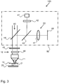
- the aforementioned autofocus sensor can also be based on the principle of dynamic focusing. Basically, a height information is converted into a 2D information, which succeeds, for example, with the aid of an astigmatic element in the detection beam path. Alternatively, for example, a Foucault cutting edge can also be used in the detection. Particularly interesting designs result from the use of special formations of the point distribution function, which in US-7,705,970 B2 and US-2011/0310266 A1 are described. US-7,705,970 B2 uses a rotational point distribution function in the form of a double helix, in which height information can be derived from the geometric alignment of the two helical cross sections relative to each other. This principle is related to FIG. 3 discussed in more detail.
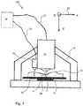
- FIG Fig. 1 Shown there is a device 100 according to the invention, which has as essential components an optical microscope 10 with a microscope objective 11 and an optical axis 14, a sample holder 20 and a reference sensor 30.
- the optical microscope 10 and the reference sensor 30 are connected via connecting lines 22, 24 to a control and evaluation device 18, which controls the microscope 10 and the reference sensor 30 and reads out measurement data in each case.
- the microscope 10, the reference sensor 30 and the sample holder 20 with a sample 12 arranged thereon are located in a housing 16.
- the sample holder 20 is a sample table of a basically known type.
- the reference sensor 30 is a optical sensor, for example, a triangulation sensor.
- the reference numeral 26 is in Fig. 1 a coordinate system shown.
- the z-axis is parallel to the optical axis 14 of the objective 11 of the optical microscope 10 and corresponds to the height direction, in which a topography of the surface 13 of the sample 12 is determined.
- This height direction z is also the direction in which the reference sensor 30 measures a distance or at least changes in distance to the reference point 32 on the sample.
- the reference sensor 30/31 may preferably collect measurement data during the entire measuring process of the microscope 10, so that any changes in distance due to disturbances can be detected.
- a structured element is initially present, which is arranged in a plane conjugate to the sample plane.
- the structured element represents a transmissive one- or two-dimensional lattice structure.
- This structure is formed by refractive and / or diffractive chromatic elements in imaged the sample space, so that here a chromatic splitting is generated, that is, the focus shifts depending on the wavelength in the z-direction.
- a polychromatic light source laser, halogen lamp, super luminescence diode
- a wavelength can be selected by a selective element in the first embodiment described.
- This selective element can be, for example, an AOTF, a prism, a grid or also a filter selection unit.
- the light can then be deflected by a deflection unit in a different direction.
- the deflection unit may, for example, be a fast-switching mirror (eg Galvo mirror), an AOD or a polarization rotation-based switching unit.
- a polarization filtering can be made.
- the deflection unit makes it possible to sequentially illuminate the grating from two sides using a collimating lens. If the lattice structure has a mirror finish, two lattice phases are accordingly imaged in the sample space.
- a beam splitter can be used for combining the transmission and reflection beam path.
- the light is then passed through a beam splitter to the sample, wherein the beam splitter is advantageously designed as a polarization beam splitter.
- a lambda / 4 plate can be arranged in the beam path, so that the light to be detected which goes to the sample and is reflected by the sample has a polarization rotated by 90 ° relative to one another and can be separated from one another as well.
- a polarization filter can furthermore be arranged in front of the detection camera.
- the wavelength can be tuned, which corresponds to a screening in the z direction. If the modulation contrast is evaluated as a function of the wavelength for each pixel, the corresponding height value of the sample is obtained. The modulation contrast is most pronounced at the wavelength whose z-focus position coincides with the sample surface.
- the structure which can also represent a 2D pinhole array (pinhole), moved to different positions and it will be taken with a camera corresponding images, but here only one light channel of the illumination is used.
- the camera can be used as a digital pinhole, so that a truly confocal image is obtained by calculating and composing the images taken at the individual positions (this corresponds, for example, to the Zeiss CSM 700).
- the height information can be derived by plotting the intensity over the wavelength.
- the structured element is completely eliminated and a sharpening function over the wavelength is determined in each case only for each local image area. This corresponds to the principle of focus variation. With sufficiently structured samples, this is sufficient to obtain height information.
- the structured element can also be an element for targeted introduction of a speckle pattern, which can be completely removed from the beam path.
- the reference sensor 30/31 may be read out parallel to each wavelength or z-shot of the microscope 10 become. If a distance change is detected, this can be taken into account passively directly in the measurement result. Another possibility is to actively respond to the distance change, for example, by changing the relative distance between the sample 12 and the microscope 10, for example by means of a movable table system as a sample holder 20.
- the Zeiss combines VivaTome with the chromatic confocal technology.
- a rotating disc is introduced with a mirrored structuring.
- the light reflected back from the sample is detected in two camera channels, which respectively correspond to a transmission or a reflection on the rotating disk.
- both a wide-field image and a confocal image can be calculated.
- the intensity information as a function of the wavelength yields the sought height information for each detection pixel.
- the wavelength is tuned, so that multiple individual recordings at a constant distance of the microscope to the sample are required. Reading out the reference sensor ensures that no artifacts occur.
- a movable pinhole array or a Nipkow disc is used.
- the pinhole array consists only of a pinhole.
- a detection of the entire sample surface is achieved by a movement (rotation, displacement) of the pinhole array.
- the spectral information or the height information coupled thereto can be obtained either with the aid of a tunable light source or with a broadband light source and spectral detection.
- the spectrometer can be realized with the aid of a line sensor. In any case, several individual measurements are required at least by the movement of the array, so that the reference measurement according to the invention makes sense here too.
- a non-movable pinhole array can be used, wherein the movement of the image of the same relative to the sample surface is realized by means of a scanning unit.
- a special feature of the reference beam path is that in the illumination, a phase element 42 is used, which is designed so that the focusing by means of the lens 11 generates a double helix-like point distribution function in the sample space.
- the lateral orientation of the double helix depends sensitively on the distance between the objective 11 and the sample surface 13 and, after back reflection, can be detected as an image on the sensor surface 48.
- the detector 48 can advantageously be designed as a quadrant diode.
- the present invention provides a novel apparatus and method that collects a total topography of a surface of a sample to be examined optically with methods known in the art at a nominally constant distance and fixed orientation between the optical sensor and the surface sample becomes.
- a reference signal is detected, which is sensitive to changes in distance between the sample body and the optical sensor, that is the optical microscope.
- the reference signal is actively or passively used to correct the topography measurement data.
Abstract
Die Erfindung betrifft eine Vorrichtung zur Erfassung von Oberflächentopographien mit einem optischen Mikroskop (10) zum mikroskopischen Erfassen einer Topographie einer Oberfläche (13) einer Probe (12) in Richtung einer Höhenkoordinate (z) in einer zeitlichen Abfolge von Einzelmessungen und mit einer Probenhalterung (20) zum Halten der Probe (12). Die Vorrichtung ist dadurch gekennzeichnet, dass ein Referenzsensor (30, 31) vorhanden ist zum Messen von Änderungen eines Höhenabstands zwischen dem Mikroskop (10) und der Probenhalterung (20) und dass eine Steuer- und Auswerteeinheit (18) vorhanden ist zum Verarbeiten von Messdaten des Mikroskops (10) und des Referenzsensors (30, 31). Die Erfindung betrifft außerdem ein Verfahren zur Erfassung von Oberflächentopographien mit einem optischen Mikroskop (10) zum mikroskopischen Erfassen einer Topographie einer Oberfläche (13) einer Probe.The invention relates to a device for detecting surface topographies with an optical microscope (10) for microscopically detecting a topography of a surface (13) of a sample (12) in the direction of a height coordinate (z) in a temporal sequence of individual measurements and with a sample holder (20 ) for holding the sample (12). The device is characterized in that a reference sensor (30, 31) is provided for measuring changes in a height distance between the microscope (10) and the sample holder (20) and that a control and evaluation unit (18) is provided for processing measurement data the microscope (10) and the reference sensor (30, 31). The invention also relates to a method for detecting surface topographies with an optical microscope (10) for microscopically detecting a topography of a surface (13) of a sample.
Description
Die vorliegende Erfindung betrifft in einem ersten Gesichtspunkt eine Vorrichtung zur Erfassung von Oberflächentopographien nach dem Oberbegriff des Anspruchs 1. In einem weiteren Gesichtspunkt bezieht sich die Erfindung auf ein Verfahren zur Erfassung von Oberflächentopographien nach dem Oberbegriff des Anspruchs 15.The present invention in a first aspect relates to a device for detecting surface topographies according to the preamble of claim 1. In a further aspect, the invention relates to a method for detecting surface topographies according to the preamble of claim 15.
Eine gattungsgemäße Vorrichtung weist ein optisches Mikroskop zum mikroskopischen Erfassen einer Topographie einer Oberfläche einer Probe in Richtung einer Höhenkoordinate auf, wobei die Topographie der Oberfläche in einer zeitlichen Abfolge von Einzelmessungen gewonnen wird. Außerdem ist eine Probenhalterung zum Halten der Probe vorhanden. Bei einem gattungsgemäßen Verfahren wird von einer Oberfläche einer Probe in einer zeitlichen Abfolge von Einzelmessungen mit einem optischen Mikroskop eine Topographie der Oberfläche in Richtung einer Höhenkoordinate erhalten.A generic device has an optical microscope for microscopically detecting a topography of a surface of a sample in the direction of a height coordinate, wherein the topography of the surface is obtained in a temporal sequence of individual measurements. There is also a sample holder for holding the sample. In a generic method, a topography of the surface in the direction of a height coordinate is obtained from a surface of a sample in a temporal sequence of individual measurements with an optical microscope.
Eine gattungsgemäße Vorrichtung und ein gattungsgemäßen Verfahren ist beispielsweise beschrieben in
Als ein Standardverfahren für die Charakterisierung von technischen Oberflächen und insbesondere für die Ableitung von Rauheitsmesswerten sowie Topographien wird heute als Standardverfahren die konfokale Mikroskopie eingesetzt. Dieses Verfahren beschreiben beispielsweise
Bei vielen konfokalen Systemen findet ein Abtasten der Probe in allen drei Raumrichtungen statt, das heißt es handelt sich um punktscannende Systeme, bei denen ein optischer Strahl in xy-Richtung über die Probe geführt wird. Zur Ableitung der Höheninformation wird zum anderen eine Bewegung der Probe relativ zur Detektoreinheit, also in z-Richtung, benötigt. Aus dem Intensitätsmaximum in Abhängigkeit von der z-Position kann für jeden x/y-Ort die Höheninformation und damit die Topographie abgeleitet werden. Zu berücksichtigen ist bei diesen Verfahren und diesen Vorrichtungen, dass eine vergleichsweise lange Zeit benötigt wird, um mit Hilfe des Rasterscans eine 3D-Topographie zu erhalten. Problematisch ist insbesondere, dass es während der xy-Scans, bei welchen eine fixierte geometrische Anordnung zwischen der Probe und dem optischen Mikroskop vorliegt, durch äußere Stöße oder Schwingungen zu unkontrollierten Bewegungen des optischen Aufbaus relativ zur Probe kommen kann, wodurch die Messergebnisse verfälscht werden. Zwar können Nachteile des xy-Rasterscans teilweise durch sogenannte konfokale Weitfeldsysteme umgangen werden, bei denen Flächenkameras zum Einsatz kommen und die einen hohen Grad an Parallelisierung aufweisen. Beispiele hierfür sind das Spinning-Disk-Verfahren mit Nipkow-Scheibe, bei dem mehrere Punkte quasi gleichzeitig nach dem konfokalen Prinzip detektiert werden. Gleichwohl kann es auch hier während einer Aufnahme bei konstanter geometrischer Ausrichtung zwischen Probe und optischem Mikroskop zu störenden Bewegungen kommen.In many confocal systems, the sample is scanned in all three spatial directions, that is to say point scanning systems in which an optical beam is guided in the xy direction over the sample. For the derivation of the height information, on the other hand, a movement of the sample relative to the detector unit, ie in the z-direction, is required. From the intensity maximum as a function of the z position, the height information and thus the topography can be derived for each x / y location. It should be noted in these methods and devices that a comparatively long time is required to obtain a 3D topography using the raster scan. In particular, it is problematic that during the xy-scans, in which there is a fixed geometric arrangement between the sample and the optical microscope, external shocks or vibrations can lead to uncontrolled movements of the optical structure relative to the sample, which falsifies the measurement results. Although disadvantages of the xy raster scan can be partially circumvented by so-called confocal wide-field systems in which area cameras are used and which have a high degree of parallelization. Examples of this are the spinning disk method with Nipkow disk, in which several points are detected virtually simultaneously according to the confocal principle. Nevertheless, interfering movements may occur during a recording with a constant geometric alignment between the sample and the optical microscope.
Als eine Aufgabe der Erfindung kann angesehen werden, eine Vorrichtung zur Erfassung von Oberflächentopographien zu schaffen und ein Verfahren zur Erfassung von Oberflächentopographien anzugeben, bei welchen im Vergleich zum Stand der Technik genauere Messergebnisse möglich sind.It can be considered as an object of the invention to provide a device for detecting surface topographies and to provide a method for detecting surface topographies in which more accurate measurement results are possible compared to the prior art.
Diese Aufgabe wird durch die Vorrichtung mit den Merkmalen des Anspruchs 1 und durch das Verfahren mit den Merkmalen des Anspruchs 15 gelöst.This object is achieved by the device having the features of claim 1 and by the method having the features of claim 15.
Die Vorrichtung der oben genannten Art ist erfindungsgemäß dadurch weitergebildet, dass ein Referenzsensor vorhanden ist, zum Messen von Änderungen eines Höhenabstands zwischen dem Mikroskop und der Probenhalterung und dass eine Steuer- und Auswerteeinheit vorhanden ist zum Verarbeiten von Messdaten des Mikroskops und des Referenzsensors.The device of the abovementioned type is developed according to the invention in that a reference sensor is provided for measuring changes in a height distance between the microscope and the sample holder and that a control and evaluation unit is provided for processing measurement data of the microscope and the reference sensor.
Das Verfahren der oben angegebenen Art ist erfindungsgemäß dadurch weitergebildet, dass während der zeitlichen Abfolge von Einzelmessungen mit einem Referenzsensor Änderungen eines Höhenabstands zwischen dem Mikroskop und einer Probenhalterung wiederholt bestimmt werden.The method of the type specified above is inventively further developed in that during the time sequence of individual measurements with a reference sensor Changes in a height distance between the microscope and a sample holder can be determined repeatedly.
Vorteilhafte Ausführungsbeispiele der erfindungsgemäßen Vorrichtung und bevorzugte Varianten des erfindungsgemäßen Verfahrens werden im Folgenden insbesondere im Zusammenhang mit den abhängigen Ansprüchen und den beigefügten Figuren beschrieben.Advantageous embodiments of the device according to the invention and preferred variants of the method according to the invention are described below in particular in conjunction with the dependent claims and the accompanying figures.
Als ein Kerngedanke der vorliegenden Erfindung kann angesehen werden, eine Anfälligkeit der Mikroskopiemethoden gegenüber äußeren Bewegungseinflüssen dadurch zu vermeiden, dass zeitlich parallel zum eigentlichen Messvorgang, also der Bestimmung einer Oberflächentopographie durch eine Mehrzahl von Einzelmessungen, eine sich wiederholende Referenzmessung durchgeführt wird. Die Ergebnisse dieser Referenzmessung können in das eigentliche Messergebnis, das heißt die Oberflächentopographie, miteingearbeitet werden oder können dazu dienen, die Messvorrichtung stabil zu halten. Die Ergebnisse der Referenzmessung können auch dadurch verwertet oder mit eingearbeitet werden, dass Messergebnisse der Bestimmung der Oberflächentopographie verworfen werden, wenn die Referenzmessung einen Abstandswert liefert, der außerhalb eines als zulässig definierten Intervalls liegt. Einzelne Messergebnisse der Oberflächentopographie können demnach verworfen werden.A core idea of the present invention can be regarded as avoiding a susceptibility of the microscopy methods to external influences of movement in that a repetitive reference measurement is performed temporally parallel to the actual measurement procedure, ie the determination of a surface topography by a plurality of individual measurements. The results of this reference measurement can be included in the actual measurement result, ie the surface topography, or can serve to keep the measuring device stable. The results of the reference measurement can also be utilized or incorporated by discarding measurement results of the determination of the surface topography, if the reference measurement provides a distance value which lies outside of an interval defined as permissible. Individual measurement results of the surface topography can therefore be discarded.
Als Oberflächentopografie oder Oberflächentopografiedaten wird für die vorliegende Anmeldung die Zuordnung einer Höhe, das heißt eines z-Koordinatenwerts, für alle Paare von Punkten x, y in einem bestimmten Bereich der Probe verstanden.For the present application, the surface topography or surface topography data is understood to mean the assignment of a height, that is to say a z coordinate value, for all pairs of points x, y in a specific region of the sample.
Die vorliegende Erfindung kann mit besonderem Vorteil eingesetzt werden bei der Reflexionsmikroskopie im Auflicht, für die Charakterisierung und die Messung von Oberflächen und insbesondere für Rauigkeitsmessungen. Die erfindungsgemäße Vorrichtung und das entsprechende Verfahren ermöglichen es, äußere Einflüsse wie Schwingungen, Stöße und ähnliches zu erfassen und mit Hinblick auf das Messergebnis entsprechend zu berücksichtigen. Das gesamte Messsystem weist daher eine besondere Robustheit gegenüber äußeren Einflüssen auf.The present invention can be used to particular advantage in reflection microscopy in reflected light, for the characterization and measurement of surfaces and in particular for roughness measurements. The device according to the invention and the corresponding method make it possible to detect external influences such as vibrations, shocks and the like and to take them into account with regard to the measurement result. The entire measuring system therefore has a particular robustness against external influences.
Es folgt ein Überblick über mikrokopische Verfahren, bei denen die Erfindung nutzbringend zum Einsatz kommen kann. Ebenso wie bei den bereits erwähnten Verfahren, bei denen eine Nipkow-Scheibe zum Einsatz kommt, funktionieren Verfahren, bei denen statt einer Nipkow-Scheibe eine andersartige schnell schaltbare Blende oder ein schnell schaltbares Mikrodisplay zum Einsatz kommt, wie beim CSM700 von Carl Zeiss, welches auf einem Multilinienscan mit digital-konfokaler Detektion beruht. Auch hier kann es während einer Aufnahme bei konstanter geometrischer Ausrichtung zwischen Probenkörper und Sensoreinheit zu störenden Bewegungen kommen, weshalb die Erfindung vorteilhaft einsetzbar ist. Dies gilt insbesondere, wenn für eine z-Positionierung mehrere Aufnahmen gemacht werden sollten, was beispielsweise der Fall sein kann, wenn eine Gesamtaufnahme von hoher Dynamik durch Kombination von Aufnahmen unterschiedlicher Belichtungszeit erzielt werden soll.The following is an overview of microscopic methods in which the invention can be usefully employed. As with the methods already mentioned, where a Nipkow disc is used, work processes in which instead of a Nipkow disc another type of fast switchable aperture or a fast switchable microdisplay is used, as in the CSM700 from Carl Zeiss, which is based on a multi-line scan with digital confocal detection based. Again, there may be disturbing movements during a recording with a constant geometric orientation between the specimen and the sensor unit, which is why the invention is advantageously used. This is especially true when multiple exposures should be made for z-positioning, which may be the case, for example, if a total high dynamic range recording is to be achieved by combining exposures of different exposure times.
Weiterhin existieren auf strukturierter Beleuchtung basierende konfokalen Weitfeldsysteme. Hier wird für jeden z-Wert ein konfokales Schnittbild errechnet aus Bildern, die mit einer z.B. durch ein Gitter gegebenen strukturierten Beleuchtung aufgenommen wurden. In der Regel kann dabei auch das Weitfeldbild erhalten werden. Es wird keine Lochblendenanordnung in der Detektion benötigt. Ein Beispiel hierfür ist das von Carl Zeiss vertriebene ApoTome-Verfahren, bei dem ein Gitter mit unterschiedlichen Phasenlagen auf die Proben abgebildet wird. Da Intensitätsmodulationen in Abhängigkeit von der Phasenlage nur für fokale Bildanteile vorliegen, kann hieraus ein optisches Schnittbild errechnet werden. Dieses Verfahren ist auch für die Vermessung von technischen Oberflächen geeignet. Bei einem anderen Verfahren werden nur zwei Gitterphasen in der Beleuchtung eingesetzt, wobei die Phasen zeitlich sequentiell durch ein Umschalten von Lichtquellen erfasst werden. Dieses Verfahren ist in
Bei einer Streifenprojektion wird ein Streifenmuster unter einem Triangulationswinkel auf eine Probenoberfläche projiziert, so dass aus der Deformation des Musters eine Höheninformation abgeleitet werden kann. In der Regel werden auch hier unterschiedlichen Phasenmuster erzeugt, um die Oberfläche vollständig zu erfassen.In a stripe projection, a stripe pattern is projected onto a sample surface at a triangulation angle, so that height information can be derived from the deformation of the pattern. As a rule, different phase patterns are also generated here in order to completely grasp the surface.
Letztlich ist allen auf strukturierter Beleuchtung basierenden Systemen gemein, dass auch hier während der Änderung des Phasenmusters Vibrationen einen störenden Einfluss auf das Messergebnis nehmen können. Die Erfindung kann deshalb überall dort vorteilhaft eingesetzt werden.After all, it is common to all systems based on structured illumination that, during the change of the phase pattern, vibrations can also have a disruptive effect on the measurement result. The invention can therefore be used advantageously everywhere.
Verwandt ist auch das Verfahren des von der Carl Zeiss vertriebenen VivaTomes, das eine sich kontinuierlich ändernde strukturierte Beleuchtung verwendet und das optische Schnittbild aus zwei parallel aufgenommenen Bildern errechnet, bei denen eines außerfokale und fokale und das andere nur außerfokale Anteile enthält. Ein Vorteil dieser auf strukturierter Beleuchtung basierenden Verfahren ist, dass parallel zum konfokalen Bild auch ein Weitfeldbild quasi in einem Schuss erhalten werden kann. Für das verbleibende Problem, dass äußere Bewegungen stören, wenn bei spielsweise bei einer z-Position mehrere Aufnahmen gemacht werden sollen, schafft die Erfindung Abhilfe.Also related is the process of the VivaTomes marketed by Carl Zeiss, which uses continuously changing structured illumination and calculates the optical cross-sectional image from two images taken in parallel, one containing extra-focal and focal and the other only extra-focal. An advantage of this method based on structured illumination is that parallel to the confocal image, a wide field image can also be obtained virtually in one shot. For the remaining problem that interfere with external movements, if for example in a z-position several shots to be made, the invention provides a remedy.
Es existieren noch andere Weitfeld-Methoden, mit denen optische Schnitte erzeugt werden können. Hier ist zum einen die sogenannte Fokus-Variation zu nennen, bei welcher die Bildschärfe in Abhängigkeit von z ausgewertet wird, um hieraus ähnlich dem konfokalen Fall ein Maximum zu errechnen. Es werden damit auch räumliche Informationen herangezogen. Ähnlich einzuordnen ist das erst kürzlich etablierte sogenannte HiLo-Verfahren, bei dem Weitfeld-Bilder mit und ohne Strukturierung aufgenommen werden, um hieraus durch den geschickten Einsatz räumlicher Bandpass-Filter ein optisches Schnittbild zu erhalten. Die Strukturierung kann dabei auch auf einem Speckle-Muster basieren. Bekannt ist auch ein Verfahren, bei welchem durch Ausnutzen der Polarisation das Verfahren der strukturierten Beleuchtung zum Einsatz kommt. Werden statt der Polarisation die Farbeigenschaften des Lichts ausgenutzt, so gelangt man zur farbkodierten strukturierten Beleuchtung. Hinsichtlich der Schwingungsanfälligkeit bestehen die gleichen Probleme wie beim Spinning Disc oder VivaTome-Verfahren, weshalb auch hier die Erfindung Vorteile bringt.There are other wide-field methods that can be used to create optical sections. Here, on the one hand, the so-called focus variation should be mentioned, in which the image sharpness is evaluated as a function of z in order to calculate a maximum similar to the confocal case. It also uses spatial information. A similar classification is the recently established so-called HiLo process, in which wide-field images are recorded with and without structuring, in order to obtain an optical cross-sectional image through the clever use of spatial bandpass filters. The structuring can also be based on a speckle pattern. Also known is a method in which the method of structured illumination is used by exploiting the polarization. If the color properties of the light are exploited instead of the polarization, then one arrives at the color-coded structured illumination. With respect to the susceptibility to vibration, there are the same problems as in Spinning Disc or VivaTome method, which is why the invention brings benefits here.
Um das z-Rastern zu vermeiden, hat sich auf der anderen Seite das chromatisch konfokale Prinzip bewährt. Hier wird in der Regel eine polychromatische Lichtquelle eingesetzt, die die interessierende Probe über ein chromatisch wirkendes refraktives und/oder diffraktives Element beleuchtet, wodurch die z-Information spektral kodiert wird. Wird nun hinter einer konfokalen Lochblende in der Detektion das Spektrum vermessen, so kann hieraus die Höheninformation abgeleitet werden. Auch möglich ist die Verwendung einer durchstimmbaren Lichtquelle mit sequentieller konfokaler Detektion, wodurch ebenfalls ein Spektrum erhalten wird. Zumeist handelt es sich bei den kommerziellen Sensoren um Punktdetektoren, die stets den Nachteil der fehlenden x-y-Parallelisierung aufweisen. Um eine vollständige Topographie zu erfassen, sind mehrere Messungen mit relativer x-y-Verstellung zwischen Probe und Sensor erforderlich. Diese Verstellung kann beispielsweise mit Hilfe einer Strahlablenkeinheit im Sensor erfolgen, so dass die geometrische Ausrichtung zwischen Probe und Sensor während des Messvorgangs konstant bleibt. Im Hinblick auf Stöße und Schwingungsbewegungen während des Messvorgangs leistet die Erfindung Abhilfe.In order to avoid z-rastering, on the other hand, the chromatic confocal principle has proven itself. Here, a polychromatic light source is usually used, which illuminates the sample of interest via a chromatically acting refractive and / or diffractive element, whereby the z-information is spectrally encoded. If now the spectrum is measured behind a confocal pinhole in the detection, then the height information can be derived therefrom. It is also possible to use a tunable light source with sequential confocal detection, whereby a spectrum is likewise obtained. In most cases, the commercial sensors are point detectors, which always have the disadvantage of missing have xy parallelization. To capture a complete topography, several measurements with relative xy adjustment between sample and sensor are required. This adjustment can take place, for example, with the aid of a beam deflecting unit in the sensor, so that the geometrical alignment between sample and sensor remains constant during the measuring process. With regard to shocks and vibration movements during the measurement process, the invention provides a remedy.
Es existieren auch Ansätze zu x-y-Parallelisierung des chromatisch konfokalen Prinzips. Eine chromatisch multifokale Anordnung mit Lochblenden-Array ist beispielsweise in
In
Eine Erweiterung zu den chromatisch konfokalen Verfahren ist die chromatisch konfokale Spektralinterferometrie, bei der ähnliche Probleme wie im rein chromatischkonfokalen Fall zutage treten und die mithin ebenfalls von der Erfindung profitieren.An extension to the chromatic confocal methods is the chromatic confocal spectral interferometry, in which similar problems as in the purely chromatic confocal case come to light and thus also benefit from the invention.
Somit handelt es sich bei den bisher beschriebenen Ansätzen um Mehrschuss-Verfahren, bei denen die Höheninformation nicht aus eine einzige Bildaufnahme ermittelt wird, sondern über mehrere Bildaufnahmen, die hinsichtlich z-Scanposition, xy-Scanposition, Wellenlänge oder Spektrometereinstellung voneinander verschieden sind. In der Regel ist es aber möglich die räumliche Ausrichtung von Probenkörper zu Sensor während des Messvorgangs konstant zu halten.Thus, the approaches described so far are multi-shot methods in which the height information is not determined from a single image acquisition, but over several images that are different from each other in terms of z-scan position, xy-scan position, wavelength or Spektrometereinstellung. In general, however, it is possible to keep the spatial orientation of sample body to sensor constant during the measurement process.
Der eigentliche Messvorgang, das heißt das mikroskopische Erfassen der Topographie einer Oberfläche mit dem optischen Mikroskop, besteht also in der Regel darin, zum Beispiel mit den oben erwähnten Verfahren von unterschiedlichen Orten in oder auf der Probe zu unterschiedlichen Zeiten Informationen zu gewinnen. Im Unterschied und ergänzend hierzu wird die Referenzmessung mit dem Referenzsensor wiederholend stets an ein und demselben Ort durchgeführt. Bei einem vorteilhaften Ausführungsbeispiel der erfindungsgemäßen Vorrichtung ist demgemäß der Referenzsensor eingerichtet zum Messen von Änderungen des Höhenabstands zwischen dem Mikroskop und einem mit der Probenhalterung starr gekoppelten Referenzpunkt. Dadurch ist eine besonders zuverlässige Bestimmung des Höhenabstands zwischen dem Mikroskop und der Probenhalterung möglich.The actual measurement process, that is to say the microscopic detection of the topography of a surface with the optical microscope, is thus generally to obtain information, for example using the methods mentioned above, from different locations in or on the sample at different times. In contrast and in addition to this, the reference measurement with the reference sensor is always carried out repeatedly in one and the same location. In an advantageous embodiment of the device according to the invention, the reference sensor is accordingly set up for measuring changes in the height distance between the microscope and a reference point rigidly coupled to the sample holder. As a result, a particularly reliable determination of the height separation between the microscope and the sample holder is possible.
Im Hinblick auf die Wahl des Referenzpunkts im Einzelnen bestehen unterschiedliche Möglichkeiten. Bei einer einfachen Variante ist der starr gekoppelte Referenzpunkt ein Punkt auf oder in der Probe. Zweckmäßig ist hierzu die Probenhalterung zum starren Halten einer Probe eingerichtet. Grundsätzlich kann der Referenzpunkt aber auch ein Punkt auf oder an der Probenhalterung sein. Diese Variante kann bevorzugt sein, wenn Proben untersucht werden, bei denen es schwierig ist, einen geeigneten Referenzpunkt zu finden. Freiheit besteht grundsätzlich auch in der konkreten Anordnung des Referenzsensors. Dieser kann entweder an dem Mikroskop oder an der Probenhalterung angeordnet sein. Um eine definierte Messung zu gewährleisten, ist es dabei zweckmäßig, wenn der Referenzsensor entweder an das Mikroskop oder an die Probenhalterung starr gekoppelt ist.There are different possibilities with regard to the choice of the reference point. In a simple variant, the rigidly coupled reference point is a point on or in the sample. Appropriately, this is the sample holder for rigid holding a sample set. In principle, however, the reference point can also be a point on or at the sample holder. This variant may be preferred when examining samples in which it is difficult to find a suitable reference point. Freedom basically also exists in the specific arrangement of the reference sensor. This can be arranged either on the microscope or on the sample holder. To ensure a defined measurement, it is expedient if the reference sensor is rigidly coupled either to the microscope or to the sample holder.
Die Messdaten des Referenzsensors können auf unterschiedliche Weise nutzbringend verwendet werden.The measurement data of the reference sensor can be usefully used in different ways.
Bei einer besonders bevorzugten Variante ist eine Verstelleinrichtung zum Verstellen eines Höhenabstands zwischen dem Mikroskop und der Probenhalterung vorhanden und die Steuer- und Auswerteeinheit wirkt mit dieser Verstelleinrichtung zusammen und ist zum Durchführen einer aktiven Regelung des Höhenabstands zwischen dem Mikroskop und dem Referenzpunkt eingerichtet. Es wird also auf Grundlage von Messdaten des Referenzsensors eine aktive Regelung des Höhenabstands durchgeführt. Besonders zweckmäßig wird dabei auf einen konstanten Höhenabstand geregelt.In a particularly preferred variant, an adjusting device for adjusting a height distance between the microscope and the sample holder is present and the control and evaluation cooperates with this adjustment and is set up to perform an active control of the height distance between the microscope and the reference point. It is therefore carried out based on measurement data of the reference sensor active control of the height difference. Particularly expedient is regulated to a constant height distance.
Prinzipiell ist aber ebenso möglich, dass eine gemessene Topographie einer Oberfläche einer Probe mit Hilfe von Messdaten des Referenzsensors im Nachhinein, also nach Messen der genannten Topographie, korrigiert wird. Die Steuer- und Auswerteeinheit ist hierzu vorteilhafterweise eingerichtet zum nachträglichen Korrigieren einer gemessenen Topographie einer Oberfläche einer Probe mit Hilfe von Messdaten des Referenzsensors. In einem einfachen Fall kann die nachträgliche Korrektur in einem Verwerfen oder Weglassen von Messpunkten der Oberflächentopografie bestehen und zwar dann, wenn ein Messwert des Referenzsensors für den Zeitpunkt, zu dem die fragliche Oberflächentopografiedaten aufgenommen wurden, nicht innerhalb eines als zulässig definierten Intervalls liegt. Die zu diesem Messzeitpunkt oder in einem zu definierenden Intervall um diesen Messzeitpunkt erhobenen Oberflächentopografiedaten werden dann nicht berücksichtigt oder, mit anderen Worten, verworfen. Bevorzugt können zum Korrigieren einer gemessenen Oberflächentopographie im Nachhinein die von dem Referenzsensor für einen jeweiligen Messzeitpunkt der Oberflächentopographie gemessenen Änderungen des Höhenabstands mit den zu dem genannten Zeitpunkt erhobenen Oberflächentopographiedaten in einer mathematischen Operation verarbeitet werden. Besonders bevorzugt können zum Korrigieren einer gemessenen Oberflächentopographie im Nachhinein die von dem Referenzsensor für einen jeweiligen Messzeitpunkt der Oberflächentopographie gemessenen Änderungen des Höhenabstands von den zu dem genannten Zeitpunkt erhobenen Oberflächentopographiedaten subtrahiert werden. Wenn also bei der Messung einer Oberflächentopographie in einer Sequenz von Messungen aus irgendeinem Grund sich der Abstand zwischen dem Mikroskop und der Probe erhöht, beispielsweise durch eine mechanische Schwingung, so weisen die erhobenen Oberflächentopographiedaten eine Fehler auf. Sie sind, wenn sich der Abstand vergrößert hat, um eben diese Abstandsvergrößerung zu groß. Durch Subtrahieren der von dem Referenzsensor für den fraglichen Messzeitpunkt erfassten Abstandsänderung, wird dieser Fehler im Nachhinein wieder korrigiert.In principle, however, it is also possible for a measured topography of a surface of a sample to be corrected with the aid of measured data of the reference sensor in hindsight, that is to say after measuring the said topography. For this purpose, the control and evaluation unit is advantageously set up for the subsequent correction of a measured topography of a surface of a sample with the aid of measured data of the reference sensor. In a simple case, the subsequent correction may be to discard or omit surface topography measurement points, if a reading of the reference sensor for the time the surface topography data in question was taken is not within an allowable defined interval. The surface topography data collected at this time of measurement or in an interval to be defined at this time of measurement are then ignored or, in other words, discarded. In order to correct a measured surface topography, the changes in the height distance measured by the reference sensor for a respective measuring time of the surface topography can preferably be processed in a mathematical operation with the surface topography data collected at the time mentioned. With particular preference, in order to correct a measured surface topography, the changes in the height distance measured by the reference sensor for a respective measurement time of the surface topography can be subtracted from the surface topography data collected at the time mentioned above. So when measuring a surface topography in a sequence of measurements from any one Because the distance between the microscope and the sample increases, for example, due to a mechanical vibration, the surface topography data collected has an error. They are, if the distance has increased to just this distance increase too large. By subtracting the distance change detected by the reference sensor for the measurement time in question, this error is subsequently corrected again.
Das optische Mikroskop kann grundsätzlich ein optisches Mikroskop bekannter Art sein. Die Vorteile der Erfindung werden in besonderer Weise erreicht, wenn das optische Mikroskop und die damit durchgeführten Mikroskopieverfahren eine endliche Zeitdauer zur Erfassung der Oberflächentopographie einer zu untersuchenden Probe benötigen, je größer, mit anderen Worten, die Wahrscheinlichkeit ist, dass es aufgrund von mechanischen Störungen zu Verfälschungen der Messergebnisse kommt. Beispielsweise kann das Mikroskop einen Scanner, insbesondere einen Punkt- und/oder Linienscanner aufweisen.The optical microscope can basically be an optical microscope of a known type. The advantages of the invention are achieved in a particular way when the optical microscope and the microscopy methods used therewith require a finite time to detect the surface topography of a sample to be examined, in other words the probability that it will increase due to mechanical disturbances Falsifications of the measurement results. For example, the microscope may have a scanner, in particular a point and / or line scanner.
Das optische Mikroskop kann beispielsweise zum Durchführen einer oder mehrerer der folgenden mikroskopischen Verfahren eingerichtet sein: Phasenverschiebungsinterferometrie, optische Kohärenztomografie, strukturierte Beleuchtung und/oder Phase-Retrieval-Mikroskopie.For example, the optical microscope may be configured to perform one or more of the following microscopic methods: phase shift interferometry, optical coherence tomography, structured illumination, and / or phase retrieval microscopy.
Eine Auflösung in Richtung der Höhenkoordinate kann bei optischen Mikroskopen insbesondere durch Ausnutzen von chromatischen Aberrationen erzielt werden. Besonders bevorzugt sind deshalb Verfahrensvarianten, bei denen die Einzelmessungen mit Licht verschiedener Wellenlängen durchgeführt werden. Im Zusammenhang mit dem Referenzsensor kommt es im Prinzip darauf an, dass hierzu ein Messgerät zum Einsatz kommt, mit welchem Änderungen des Höhenabstands zwischen dem Mikroskop und der Probenhalterung mit hinreichender Genauigkeit gemessen werden können. Grundsätzlich können hierfür sehr unterschiedliche Sensoren zum Einsatz kommen. Besonders genaue Abstandsmessungen sind beispielsweise mit kapazitiven Sensoren, mit induktiven Sensoren, Wirbelstromsensoren und/oder mit magneto-induktiven Sensoren möglich.A resolution in the direction of the height coordinate can be achieved in optical microscopes, in particular by exploiting chromatic aberrations. Process variants in which the individual measurements are carried out with light of different wavelengths are therefore particularly preferred. In principle, it is important in connection with the reference sensor that a measuring device is used with which changes in the height distance between the microscope and the sample holder can be measured with sufficient accuracy. In principle, very different sensors can be used for this purpose. Particularly accurate distance measurements are possible, for example, with capacitive sensors, with inductive sensors, eddy-current sensors and / or with magneto-inductive sensors.
Alternativ oder ergänzend können auch Beschleunigungssensoren zum Einsatz kommen. Diese können besonders bevorzugt angebracht sein an der Probenhalterung, die beispielswiese ein beweglicher Probentisch grundsätzlich bekannter Art sein kann. Relativbewegungen zwischen Mikroskop und Probenhalterung / Tischsystem können so kontinuierlich erfasst werden.Alternatively or additionally, acceleration sensors can also be used. These may be particularly preferably attached to the sample holder, the example meadow can be a moving sample table basically known type. Relative movements between the microscope and the sample holder / table system can thus be recorded continuously.
Besonders bevorzugt werden für die Referenzsensoren optische Sensoren eingesetzt. Dabei kann es sich insbesondere um einen konfokalen Sensor, einen chromatisch konfokalen Sensor, einen interferometrischen Sensor, einen Autofokussensor, einen Triangulationssensor, einen stereoskopischen Abstandssensor, einen Flugzeitsensor, einen Phasenversatz messende optische Sensoren und/oder einen Sensor mit einer Foucault-Schneide handeln.Particular preference is given to using optical sensors for the reference sensors. This may in particular be a confocal sensor, a chromatic confocal sensor, an interferometric sensor, an autofocus sensor, a triangulation sensor, a stereoscopic distance sensor, a time of flight sensor, a phase shift optical sensors and / or a sensor with a Foucault cutting edge.
Der erwähnte Autofokussensor kann auch auf dem Prinzip der dynamischen Fokussierung basieren. Dabei wird grundsätzlich eine Höheninformation in eine 2D-Information umgewandelt, was beispielsweise unter Zuhilfenahme eines astigmatischen Elements im Detektionsstrahlengang gelingt. Alternativ kann beispielsweise auch eine Foucault-Schneide in der Detektion verwendet werden. Besonders interessante Ausführungen ergeben sich unter Ausnutzung von besonderen Formungen der Punktverteilungsfunktion, die in
Ein besonders kompakter Aufbau kann erzielt werden, wenn der Referenzsensor ein optischer Sensor ist und der Referenzsensor und das Mikroskop gemeinsame Optikmittel, insbesondere ein gemeinsames Objektiv, aufweisen. Beispielsweise kann ein Abtaststrahl eines als Referenzsensor wirkenden optischen Sensors über einen Strahlteiler in den Strahlengang des optischen Mikroskops eingekoppelt und/oder kann mit dessen Objektiv auf die Probe geleitet werden.A particularly compact construction can be achieved if the reference sensor is an optical sensor and the reference sensor and the microscope have common optical means, in particular a common objective. For example, a scanning beam of an optical sensor acting as a reference sensor can be coupled into the beam path of the optical microscope via a beam splitter and / or can be guided with its objective onto the sample.
Weitere Vorteil und Merkmale der vorliegenden Erfindung werden mit Bezug auf die beigefügten Figuren erläutert. Hierin zeigen:
- Fig. 1:
- eine schematische Darstellung eines ersten Ausführungsbeispiels einer erfindungsgemäßen Vorrichtung;
- Fig. 2:
- eine schematische Ansicht eines zweiten Ausführungsbeispiels einer erfindungsgemäßen Vorrichtung; und
- Fig. 3:
- eine schematische Ansicht eines dritten Ausführungsbeispiels einer erfindungsgemäßen Vorrichtung.
- Fig. 1:
- a schematic representation of a first embodiment of a device according to the invention;
- Fig. 2:
- a schematic view of a second embodiment of a device according to the invention; and
- 3:
- a schematic view of a third embodiment of a device according to the invention.
Gleiche oder gleich wirkende Komponenten sind in den Figuren in der Regel mit denselben Bezugszeichen gekennzeichnet.Identical or equivalent components are usually identified in the figures with the same reference numerals.
Ein erstes Ausführungsbeispiel einer erfindungsgemäßen Vorrichtung wird mit Bezug auf
Mit dem Bezugszeichen 26 ist in
Das optische Mikroskop 10 kann im Prinzip ein Säulensystem oder auch, wie in
Bei dem in
Zu den im Folgenden beschriebenen Ausführungsbeispielen wird auf
Bei einem Ausführungsbeispiel des Mikroskops (siehe
Es ist somit gemäß diesem Ausführungsbeispiel möglich, unterschiedliche Gitterphasen auf die Probe abzubilden und zu detektieren. Gleichzeitig kann dabei die Wellenlänge durchgestimmt werden, was einer Rasterung in z-Richtung entspricht. Wird für jedes Pixel der Modulationskontrast in Abhängigkeit von der Wellenlänge ausgewertet, so erhält man den entsprechenden Höhenwert der Probe. Der Modulationskontrast ist bei der Wellenlänge am stärksten ausgeprägt, deren z-Fokusposition mit der Probenoberfläche übereinstimmt. Alternativ kann natürlich auch ein optisches Schnittbild für jede Wellenlänge mit den gängigen Verfahren der strukturierten Beleuchtung berechnet werden, und es wird für jedes Pixel das Maximum der Intensität des Schnittbilds über der Wellenlänge ermittelt. Es versteht sich von selbst, dass das System dabei hinsichtlich der spektralen Eigenschaften von Lichtquelle, Optik und Detektoreinheit hinreichend kalibriert sein muss.It is thus possible according to this embodiment to image and detect different grating phases on the sample. At the same time, the wavelength can be tuned, which corresponds to a screening in the z direction. If the modulation contrast is evaluated as a function of the wavelength for each pixel, the corresponding height value of the sample is obtained. The modulation contrast is most pronounced at the wavelength whose z-focus position coincides with the sample surface. Alternatively, it is of course also possible to calculate an optical slice image for each wavelength using the conventional methods of structured illumination, and the maximum of the intensity of the slice image over the wavelength is determined for each pixel. It goes without saying that that System must be sufficiently calibrated with respect to the spectral properties of light source, optics and detector unit.
In einer anderen Variante wird die Struktur, die auch ein 2D-Pinhole-Array (Pinhole = Lochblende) darstellen kann, auf verschiedene Positionen bewegt und es werden mit einer Kamera entsprechende Bilder aufgenommen, wobei hier aber nur jeweils ein Lichtkanal der Beleuchtung verwendet wird. Die Kamera kann gleichsam als digitales Pinhole verwendet werden, so dass ein echt konfokales Bild durch Verrechnen und Zusammensetzen der bei den einzelnen Positionen aufgenommenen Bilder erhalten wird (dies entspricht beispielsweise dem Zeiss CSM 700). Auch hier kann dann durch Auftragen der Intensität über die Wellenlänge die Höheninformation abgeleitet werden.In another variant, the structure, which can also represent a 2D pinhole array (pinhole), moved to different positions and it will be taken with a camera corresponding images, but here only one light channel of the illumination is used. The camera can be used as a digital pinhole, so that a truly confocal image is obtained by calculating and composing the images taken at the individual positions (this corresponds, for example, to the Zeiss CSM 700). Here, too, the height information can be derived by plotting the intensity over the wavelength.
In einer weiteren Variante entfällt das strukturierte Element komplett und es wird jeweils nur für jeden lokalen Bildbereich eine Schärfefunktion über die Wellenlänge ermittelt. Dies entspricht dem Prinzip der Fokusvariation. Bei hinreichend strukturierten Proben reicht auch dies aus, um Höheninformationen zu erhalten.In a further variant, the structured element is completely eliminated and a sharpening function over the wavelength is determined in each case only for each local image area. This corresponds to the principle of focus variation. With sufficiently structured samples, this is sufficient to obtain height information.
Ähnlich gestaltet sich ein Aufbau, der nach dem Prinzip des HiLo-Verfahrens funktioniert. Das strukturierte Element kann hier auch ein Element zu gezielten Einführung eines Speckle-Patterns darstellen, welches komplett aus dem Strahlengang entfernt werden kann.Similarly, a structure that works on the principle of HiLo method designed. The structured element can also be an element for targeted introduction of a speckle pattern, which can be completely removed from the beam path.
Wichtig im Sinn der Erfindung ist, dass zur Erfassung der Höhenwerte sequentielle Aufnahmen notwendig sind. Zum einen werden bei Verwendung einer Gitterstruktur beispielsweise unterschiedliche Gitterphasen auf die Probe abgebildet und hintereinander detektiert. Zum anderen wird die Wellenlänge durchgestimmt, um unterschiedliche z-Positionen im Probenraum zu erfassen. Von Bedeutung ist, dass hierbei stets die räumliche Beziehung zwischen Probenoberfläche und Detektoreinheit bestehen bleibt, das heißt, die Probe wird relativ zum Mikroskop nicht bewegt. Äußere Einflüsse können aber zu einer ungewollten Bewegung und auch somit einer Abstandänderung während des Messvorgangs führen, wodurch Artefakte auftreten können. Mit Hilfe des erfindungsgemäßen Referenzsensors 30/31 ist es nun möglich, solche Abstandänderungen zu erfassen. Beispielsweise kann der Referenzsensor 30/31 parallel zu jeder Wellenlänge bzw. z-Aufnahme des Mikroskops 10 ausgelesen werden. Wird eine Abstandänderung festgestellt, so kann diese direkt im Messergebnis passiv berücksichtigt werden. Eine weitere Möglichkeit ist, auf die Abstandänderung aktiv zu reagieren, indem beispielsweise der relative Abstand zwischen der Probe 12 und dem Mikroskop 10 z.B. mit Hilfe eines beweglichen Tischsystems als Probenhalterung 20 geändert wird.It is important in the sense of the invention that sequential recordings are necessary to record the altitude values. On the one hand, for example, when using a grid structure, different grid phases are imaged onto the sample and detected one behind the other. On the other hand, the wavelength is tuned to detect different z-positions in the sample space. It is important that in this case the spatial relationship between the sample surface and the detector unit always remains, ie the sample is not moved relative to the microscope. However, external influences can lead to unwanted movement and thus to a change in distance during the measuring process, as a result of which artifacts can occur. With the aid of the
Ein typischer Messablauf kann beispielsweise folgendermaßen aussehen:
- 1. Einstellen des optimalen Messabstands zwischen der
Probe 12und dem Mikroskop 10. Hierzu kann ein Signal des Mikroskops 10 selbst oder aber ein Signal desReferenzsensors 30/31 verwendet werden. - 2. Durchführen der Messung bei nominal konstantem Abstand zwischen der
Probe 12und dem Mikroskop 10 und gleichzeitiges Auslesen desReferenzsensors 30/31, mit: - 2a. Berücksichtigen
der Werte Referenzsensors 30/31 bei der Auswertung der Oberflächentopographie derProbe 12
oder - 2b. Korrektur des Messabstands während der Messung anhand der Messwerte des
Referenzsensors 30/31.
- 1. Setting the optimal measuring distance between the
sample 12 and themicroscope 10. For this purpose, a signal of themicroscope 10 itself or a signal of thereference sensor 30/31 can be used. - 2. Performing the measurement at a nominally constant distance between the
sample 12 and themicroscope 10 and simultaneous reading of thereference sensor 30/31, with: - 2a. Consider the values of
reference sensor 30/31 when evaluating the surface topography ofsample 12
or - 2 B. Correction of the measuring distance during the measurement based on the measured values of the
reference sensor 30/31.
Ein weiteres Ausführungsbeispiel (
Bei einem weiteren Ausführungsbeispiel für das Mikroskop im Sinn der chromatisch konfokalen Technologie kommt ein bewegliches Lochblenden-Array bzw. eine Nipkow-Scheibe zum Einsatz. Im Extremfall besteht das Lochblenden-Array nur aus einer Lochblende. Eine Erfassung der gesamten Probenoberfläche wird durch eine Bewegung (Rotation, Verschiebung) des Lochblenden-Arrays erreicht. Die spektrale Information bzw. die hiermit gekoppelte Höheninformation kann entweder mit Hilfe einer durchstimmbaren Lichtquelle oder aber mit einer breitbandigen Lichtquelle und spektraler Detektion erhalten werden. Im Fall der einfachen Lochblende kann das Spektrometer mit Hilfe eines Zeilensensors realisiert werden. In jedem Fall werden mindestens durch die Bewegung des Arrays mehrere Einzelmessungen benötigt, so dass auch hier die erfindungsgemäße Referenzmessung sinnvoll ist.In a further exemplary embodiment of the microscope in the sense of chromatically confocal technology, a movable pinhole array or a Nipkow disc is used. In extreme cases, the pinhole array consists only of a pinhole. A detection of the entire sample surface is achieved by a movement (rotation, displacement) of the pinhole array. The spectral information or the height information coupled thereto can be obtained either with the aid of a tunable light source or with a broadband light source and spectral detection. In the case of the simple pinhole, the spectrometer can be realized with the aid of a line sensor. In any case, several individual measurements are required at least by the movement of the array, so that the reference measurement according to the invention makes sense here too.
Statt eines beweglichen Lochblenden-Arrays kann auch ein nichtbewegliches Lochblenden-Array zum Einsatz kommen, wobei die Bewegung der Abbildung desselben relativ zur Probenoberfläche mit Hilfe einer Scaneinheit realisiert wird.Instead of a movable pinhole array, a non-movable pinhole array can be used, wherein the movement of the image of the same relative to the sample surface is realized by means of a scanning unit.
Ein besonders bevorzugtes Ausführungsbeispiel einer erfindungsgemäßen Vorrichtung 103 schließlich ist in
Bei der Anordnung in
Eine Besonderheit des Referenzstrahlengangs besteht darin, dass in der Beleuchtung ein Phasenelement 42 zum Einsatz kommt, welches so gestaltet ist, dass die Fokussierung mit Hilfe des Objektivs 11 eine doppelhelixartige Punktverteilungsfunktion im Probenraum erzeugt. Die laterale Ausrichtung der Doppelhelix hängt empfindlich vom Abstand zwischen dem Objektiv 11 und der Probenoberfläche 13 ab und kann nach Rückreflektion als Bild auf der Sensoroberfläche 48 erfasst werden. Dabei kann der Detektor 48 vorteilhafterweise als Quadrantendiode ausgeführt sein.A special feature of the reference beam path is that in the illumination, a
Werden nun die Messsignale des Detektors 48 gleichzeitig mit den zur Erfassung der Oberflächentopographie notwendigen sequentiellen Einzelmessungen des optischen Mikroskops 10 ausgelesen, so können, wie oben beschrieben, störende Bewegungen erfasst und/oder korrigiert werden. Prinzipiell ist auch möglich, dass das Phasenelement 42 an einer anderen Stelle, beispielsweise im Detektionsstrahlengang, platziert ist. Optional können außerdem eine Lambda/4-Platte 45 zur Drehung der Polarisation und/oder ein DOE (diffraktives optisches Element) oder ein anderes Element zur Einführung einer chromatischen Aberration im Strahlengang positioniert sein.If the measuring signals of the
Es wird darauf hingewiesen, dass neben dem beschriebenen Einsatz in einem chromatisch konfokalen Messsystem auch andere Messsysteme möglich sind, die sich dadurch auszeichnen, dass der Abstand zwischen Probe und Messkopf bei der Durchführung unterschiedlicher notwendiger Einzelmessungen nicht verändert wird. Hier sind beispielsweise denkbar:
- 1. Phase-Shifting-Interferometry
- 2. Optische Kohärenztomographie
- 3. Messsysteme mit strukturierter Beleuchtung, bei denen für den Messvorgang das Beleuchtungsmuster geändert werden muss: Streifenprojektion, ApoTome
- 4. Messsysteme, bei denen Intensitätsinformationen bei unterschiedliche Sensorpositionen verrechnet werden, die sequentiell erhalten werden: Phase Retrieval
- 5. Photometrie mit unterschiedlichen Schattenbildern
- 6. Rotational Lateral Shearing (Höheninformation aus DIC-Bildern mit unterschiedlichen Shearrichtungen)
- 1st phase-shifting interferometry
- 2. Optical coherence tomography
- 3. Measurement systems with structured illumination, where the illumination pattern must be changed for the measurement process: fringe projection, ApoTome
- 4. Measuring systems in which intensity information is calculated at different sensor positions, which are obtained sequentially: Phase Retrieval
- 5. Photometry with different silhouettes
- 6. Rotational lateral shearing (height information from DIC images with different shear directions)
Mit der vorliegenden Erfindung wird eine neuartige Vorrichtung und ein neuartiges Verfahren bereitgestellt, mit welchen eine Gesamt-Topographie einer Oberfläche einer zu untersuchenden Probe optisch mit aus dem Stand der Technik bekannten Methoden bei nominal konstantem Abstand und fixierter Ausrichtung zwischen dem optischen Sensor und der Oberflächenprobe erfasst wird. Während des Messvorgangs wird dabei ein Referenzsignal mit erfasst, welches empfindlich ist für Abstandsänderungen zwischen dem Probenkörper und dem optischen Sensor, das heißt dem optischen Mikroskop. Das Referenzsignal wird aktiv oder passiv zur Korrektur der Topographiemessdaten herangezogen.The present invention provides a novel apparatus and method that collects a total topography of a surface of a sample to be examined optically with methods known in the art at a nominally constant distance and fixed orientation between the optical sensor and the surface sample becomes. During the measurement process, a reference signal is detected, which is sensitive to changes in distance between the sample body and the optical sensor, that is the optical microscope. The reference signal is actively or passively used to correct the topography measurement data.
Claims (19)
mit einem optischen Mikroskop (10) zum mikroskopischen Erfassen einer Topographie einer Oberfläche (13) einer Probe (12) in Richtung einer Höhenkoordinate (z) in einer zeitlichen Abfolge von Einzelmessungen und
mit einer Probenhalterung (20) zum Halten der Probe (12),
dadurch gekennzeichnet,
dass ein Referenzsensor (30, 31) vorhanden ist zum Messen von Änderungen eines Höhenabstands zwischen dem Mikroskop (10) und der Probenhalterung (20) und
dass eine Steuer- und Auswerteeinheit (18) vorhanden ist zum Verarbeiten von Messdaten des Mikroskops (10) und des Referenzsensors (30, 31).Device for detecting surface topographies
with an optical microscope (10) for microscopically detecting a topography of a surface (13) of a sample (12) in the direction of a height coordinate (z) in a temporal sequence of individual measurements and
with a sample holder (20) for holding the sample (12),
characterized,
that a reference sensor (30, 31) is provided for measuring changes in a height distance between the microscope (10) and the specimen holder (20) and
that a control and evaluation unit (18) is present for processing measurement data of the microscope (10) and the reference sensor (30, 31).
dadurch gekennzeichnet,
dass der Referenzsensor (30, 31) eingerichtet ist zum Messen von Änderungen des Höhenabstands zwischen dem Mikroskop (10) und einem mit der Probenhalterung (20) starr gekoppelten Referenzpunkt.Device according to claim 1,
characterized,
that the reference sensor (30, 31) is arranged for measuring changes in the height distance between the microscope (10) and rigidly coupled with one of the sample holder (20) reference point.
dadurch gekennzeichnet,
dass die Probenhalterung (20) zum starren Halten einer Probe (12) eingerichtet ist und
dass der starr gekoppelte Referenzpunkt ein Punkt auf oder in der Probe (12) ist.Device according to claim 2,
characterized,
that the sample holder (20) is arranged for rigidly holding a sample (12) and
that the rigidly coupled reference point is a point on or in the sample (12).
dadurch gekennzeichnet,
dass der Referenzpunkt ein Punkt (34) auf oder an der Probenhalterung (20) ist.Device according to claim 2,
characterized,
that the reference point is a point (34) on or to the sample holder (20).
dadurch gekennzeichnet,
dass der Referenzsensor (30, 31) entweder an das Mikroskop (10) oder an die Probenhalterung (20) starr gekoppelt ist.Device according to one of claims 1 to 4,
characterized,
in that the reference sensor (30, 31) is rigidly coupled either to the microscope (10) or to the sample holder (20).
dadurch gekennzeichnet,
dass eine Verstelleinrichtung zum Verstellen eines Höhenabstands zwischen dem Mikroskop (10) und der Probenhalterung (20) vorhanden ist und dass die Steuer- und Auswerteeinheit (18) Verstelleinrichtung zusammenwirkt und zum Durchführen einer aktiven Regelung des Höhenabstands zwischen der Mikroskop (10) und dem Referenzpunkt, insbesondere auf einen konstanten Wert, eingerichtet ist.Device according to one of claims 1 to 5,
characterized,
in that an adjustment device for adjusting a vertical distance between the microscope (10) and the sample holder (20) is present and that the control and evaluation unit (18) cooperates adjusting device and for performing an active regulation of the height distance between the microscope (10) and the reference point , in particular to a constant value, is set up.
dadurch gekennzeichnet,
dass die Steuer- und Auswerteeinheit (18) eingerichtet ist zum nachträglichen Korrigieren einer gemessenen Topographie einer Oberfläche (13) einer Probe (12) mit Hilfe von Messdaten des Referenzsensors (30, 31).Device according to one of claims 1 to 5,
characterized,
in that the control and evaluation unit (18) is set up for the subsequent correction of a measured topography of a surface (13) of a sample (12) with the aid of measured data of the reference sensor (30, 31).
dadurch gekennzeichnet,
dass die Steuer- und Auswerteeinheit (18) eingerichtet ist zum Korrigieren einer gemessenen Oberflächentopographie dadurch, dass die von dem Referenzsensor (30, 31) für einen jeweiligen Messzeitpunkt der Messung der Oberflächentopographie gemessenen Änderung des Höhenabstands mit den gemessenen Oberflächentopographiedaten mathematisch verarbeitet werden, insbesondere dadurch, dass die von dem Referenzsensor (30, 31) für einen jeweiligen Messzeitpunkt der Messung der Oberflächentopographie gemessenen Änderung des Höhenabstands von den gemessenen Oberflächentopographiedaten subtrahiert werden.Device according to claim 7,
characterized,
that the control and evaluation unit (18) is adapted for correcting a measured surface topography characterized in that the from the reference sensor (30, 31) measured for a respective measurement time of the measurement of the surface topography modification of the height distance with the measured surface topography data are processed mathematically, in particular by in that the change measured by the reference sensor (30, 31) for a respective measurement time of measurement of the surface topography of the height distance are subtracted from the measured surface topography data.
dadurch gekennzeichnet,
dass das Mikroskop (10) einen Scanner, insbesondere einen Punkt- und/oder Linienscanner, aufweist.Device according to one of claims 1 to 8,
characterized,
in that the microscope (10) has a scanner, in particular a point and / or line scanner.
dadurch gekennzeichnet,
dass das Mikroskop (10) zum Durchführen einer oder mehrerer der folgenden mikroskopischen Verfahren eingerichtet ist:
characterized,
in that the microscope (10) is set up for performing one or more of the following microscopic methods:
dadurch gekennzeichnet,
dass der Referenzsensor (30, 31) einen kapazitiven Sensor und/oder einen induktiven Sensor aufweist.Device according to one of claims 1 to 10,
characterized,
that the reference sensor (30, 31) comprises a capacitive sensor and / or an inductive sensor.
dadurch gekennzeichnet,
dass der Referenzsensor (30, 31) mindestens einen Beschleunigungssensor aufweist.Device according to one of claims 1 to 11,
characterized,
that the reference sensor (30, 31) has at least one acceleration sensor.
dadurch gekennzeichnet,
dass der Referenzsensor (30, 31) mindestens einen optischen Sensor aufweist, insbesondere einen konfokalen Sensor, einen chromatisch konfokalen Sensor, einen interferometrischen Sensor, einen Autofokussensor, einen Triangulationssensor und/oder einen Sensor mit einer Foucault-Schneide.Device according to one of claims 1 to 12,
characterized,
in that the reference sensor (30, 31) has at least one optical sensor, in particular a confocal sensor, a chromatic confocal sensor, an interferometric sensor, an autofocus sensor, a triangulation sensor and / or a sensor with a Foucault cutting edge.
dadurch gekennzeichnet,
dass der Referenzsensor ein optischer Sensor ist und
dass der Referenzsensor und das Mikroskop (10) gemeinsame Optikmittel, insbesondere ein gemeinsames Objektiv (11), aufweisen.Device according to claim 13,
characterized,
that the reference sensor is an optical sensor and
that the reference sensor and the microscope (10) common optical means, in particular a common lens (11).
bei dem von einer Oberfläche (13) einer Probe (12) in einer zeitlichen Abfolge von Einzelmessungen mit einem optischen Mikroskop (10) eine Topographie der Oberfläche (13) in Richtung einer Höhenkoordinate (z) erhalten wird,
dadurch gekennzeichnet,
dass während der zeitlichen Abfolge von Einzelmessungen mit einem Referenzsensor (30, 31) Änderungen eines Höhenabstands zwischen dem Mikroskop (10) und einer Probehalterung (20) wiederholt bestimmt werden.Method for detecting surface topographies,
in which a topography of the surface (13) in the direction of a height coordinate (z) is obtained from a surface (13) of a sample (12) in a temporal sequence of individual measurements with an optical microscope (10),
characterized,
that during the time sequence of individual measurements with a reference sensor (30, 31), changes in a height distance between the microscope (10) and a sample holder (20) are determined repeatedly.
dadurch gekennzeichnet,
dass auf Grundlage von Messdaten des Referenzsensors (30, 31) eine aktive Regelung des Höhenabstands durchgeführt wird.Method according to claim 15,
characterized,
that an active control of the height distance is performed based on measured data of the reference sensor (30, 31).
dadurch gekennzeichnet,
dass eine gemessene Topographie einer Oberfläche (13) einer Probe (12) mit Hilfe von Messdaten des Referenzsensors (30, 31) im Nachhinein korrigiert wird.Method according to claim 15,
characterized,
in that a measured topography of a surface (13) of a sample (12) is corrected with the aid of measurement data of the reference sensor (30, 31) in retrospect.
dadurch gekennzeichnet,
dass die Einzelmessungen mit Licht verschiedener Wellenlänge durchgeführt werden.Method according to one of claims 15 to 17,
characterized,
that the individual measurements are carried out with light of different wavelengths.
dadurch gekennzeichnet,
dass zum Korrigieren einer gemessenen Oberflächentopographie im Nachhinein die von dem Referenzsensor für einen jeweiligen Messzeitpunkt der Oberflächentopographie gemessenen Änderungen des Höhenabstands mit den für diesen Zeitpunkt gemessenen Oberflächentopographiedaten mathematisch verarbeitet werden,
insbesondere dass zum Korrigieren einer gemessenen Oberflächentopographie im Nachhinein die von dem Referenzsensor für einen jeweiligen Messzeitpunkt der Oberflächentopographie gemessenen Änderungen des Höhenabstands von den für diesen Zeitpunkt gemessenen Oberflächentopographiedaten subtrahiert werden.Method according to one of claims 15 to 18,
characterized,
in that, in order to correct a measured surface topography, the changes in the height distance measured by the reference sensor for a respective measuring time of the surface topography are mathematically processed with the surface topography data measured for that time,
in particular, that in order to correct a measured surface topography, in retrospect, the changes in the height distance measured by the reference sensor for a respective measurement time of the surface topography are subtracted from the surface topography data measured for that time point.
Applications Claiming Priority (1)
| Application Number | Priority Date | Filing Date | Title |
|---|---|---|---|
| DE102015108912.2A DE102015108912A1 (en) | 2015-06-05 | 2015-06-05 | Apparatus and method for detecting surface topographies |
Publications (2)
| Publication Number | Publication Date |
|---|---|
| EP3101385A1 true EP3101385A1 (en) | 2016-12-07 |
| EP3101385B1 EP3101385B1 (en) | 2020-10-07 |
Family
ID=55650344
Family Applications (1)
| Application Number | Title | Priority Date | Filing Date |
|---|---|---|---|
| EP16163678.2A Active EP3101385B1 (en) | 2015-06-05 | 2016-04-04 | Device and method for detecting surface topographies |
Country Status (2)
| Country | Link |
|---|---|
| EP (1) | EP3101385B1 (en) |
| DE (1) | DE102015108912A1 (en) |
Cited By (2)
| Publication number | Priority date | Publication date | Assignee | Title |
|---|---|---|---|---|
| CN107621235A (en) * | 2017-08-26 | 2018-01-23 | 东莞市三姆森光电科技有限公司 | Mobile phone curved surface housing profile measuring method and its measuring apparatus based on Spectral Confocal technology |
| CN109141325A (en) * | 2018-09-14 | 2019-01-04 | 上海交通大学 | The contactless measurement and device of metal surface coated layer thickness |
Families Citing this family (2)
| Publication number | Priority date | Publication date | Assignee | Title |
|---|---|---|---|---|
| GB2583369B (en) * | 2019-04-25 | 2021-09-15 | Andor Tech Limited | Microscope with focusing system |
| DE102019113975B4 (en) | 2019-05-24 | 2023-10-19 | Abberior Instruments Gmbh | Method and device for monitoring the focus state of a microscope and microscope |
Citations (8)
| Publication number | Priority date | Publication date | Assignee | Title |
|---|---|---|---|---|
| DE102006044235A1 (en) * | 2006-09-15 | 2008-03-27 | Leica Microsystems Cms Gmbh | Arrangement for determining the distance, capacitive distance sensor and method for automatically focusing a microscope |
| DE102007018048A1 (en) | 2007-04-13 | 2008-10-16 | Michael Schwertner | Method and arrangement for optical imaging with depth discrimination |
| DE102007019267A1 (en) | 2007-04-24 | 2008-10-30 | Degudent Gmbh | Measuring arrangement and method for three-dimensional measuring of an object |
| US7705970B2 (en) | 2006-06-05 | 2010-04-27 | The Regents Of The University Of Colorado | Method and system for optical imaging and ranging |
| US20110310266A1 (en) | 2010-06-22 | 2011-12-22 | Shingo Kato | Image pickup apparatus |
| US20130155413A1 (en) * | 2008-11-26 | 2013-06-20 | Zygo Corporation | Low coherence interferometry with scan error correction |
| DE102012009836A1 (en) | 2012-05-16 | 2013-11-21 | Carl Zeiss Microscopy Gmbh | Light microscope and method for image acquisition with a light microscope |
| EP2789968A1 (en) * | 2011-12-07 | 2014-10-15 | Konica Minolta, Inc. | Shape-measuring device |
-
2015
- 2015-06-05 DE DE102015108912.2A patent/DE102015108912A1/en not_active Withdrawn
-
2016
- 2016-04-04 EP EP16163678.2A patent/EP3101385B1/en active Active
Patent Citations (8)
| Publication number | Priority date | Publication date | Assignee | Title |
|---|---|---|---|---|
| US7705970B2 (en) | 2006-06-05 | 2010-04-27 | The Regents Of The University Of Colorado | Method and system for optical imaging and ranging |
| DE102006044235A1 (en) * | 2006-09-15 | 2008-03-27 | Leica Microsystems Cms Gmbh | Arrangement for determining the distance, capacitive distance sensor and method for automatically focusing a microscope |
| DE102007018048A1 (en) | 2007-04-13 | 2008-10-16 | Michael Schwertner | Method and arrangement for optical imaging with depth discrimination |
| DE102007019267A1 (en) | 2007-04-24 | 2008-10-30 | Degudent Gmbh | Measuring arrangement and method for three-dimensional measuring of an object |
| US20130155413A1 (en) * | 2008-11-26 | 2013-06-20 | Zygo Corporation | Low coherence interferometry with scan error correction |
| US20110310266A1 (en) | 2010-06-22 | 2011-12-22 | Shingo Kato | Image pickup apparatus |
| EP2789968A1 (en) * | 2011-12-07 | 2014-10-15 | Konica Minolta, Inc. | Shape-measuring device |
| DE102012009836A1 (en) | 2012-05-16 | 2013-11-21 | Carl Zeiss Microscopy Gmbh | Light microscope and method for image acquisition with a light microscope |
Non-Patent Citations (1)
| Title |
|---|
| RAHLVES, SEEWIG: "Optisches Messen technischer Oberflächen", 2009, BEUTH VERLAG GMBH |
Cited By (3)
| Publication number | Priority date | Publication date | Assignee | Title |
|---|---|---|---|---|
| CN107621235A (en) * | 2017-08-26 | 2018-01-23 | 东莞市三姆森光电科技有限公司 | Mobile phone curved surface housing profile measuring method and its measuring apparatus based on Spectral Confocal technology |
| CN107621235B (en) * | 2017-08-26 | 2024-02-27 | 东莞市三姆森光电科技有限公司 | Method and equipment for measuring contour of curved surface shell of mobile phone based on spectral confocal technology |
| CN109141325A (en) * | 2018-09-14 | 2019-01-04 | 上海交通大学 | The contactless measurement and device of metal surface coated layer thickness |
Also Published As
| Publication number | Publication date |
|---|---|
| EP3101385B1 (en) | 2020-10-07 |
| DE102015108912A1 (en) | 2016-12-08 |
Similar Documents
| Publication | Publication Date | Title |
|---|---|---|
| EP2673671B1 (en) | Microscope having an autofocusing device and autofocusing method for microscopes | |
| DE112005000639B4 (en) | Device and method for combined interferometric and image-based geometry detection, in particular in microsystem technology | |
| EP2592462B1 (en) | Method and assembly for auto-focussing a microscope | |
| EP1299691B1 (en) | Method for carrying out the non-contact measurement of geometries of objects | |
| WO2013171309A1 (en) | Light microscope and method for image recording using a light microscope | |
| EP2437027A2 (en) | Device and method for three dimensional optical mapping of a sample | |
| DE102014108353A1 (en) | Method and device for the determination of geometries on measured objects by means of a combined sensor system | |
| DE102013016368A1 (en) | Light microscope and microscopy method for examining a microscopic sample | |
| WO2006032561A1 (en) | Optical measuring device for measuring several surfaces of a measuring object | |
| EP3101385B1 (en) | Device and method for detecting surface topographies | |
| WO2014023344A1 (en) | Improved chromatic sensor and method | |
| WO2016193037A1 (en) | Method for determining spatially resolved height information of a sample by means of a wide-field microscope, and wide-field microscope | |
| DE112015002582T5 (en) | Adjustment system for a phase modulation element and adjustment method for a phase modulation element | |
| WO2015044035A1 (en) | Confocal light microscope and method for examining a sample using a confocal light microscope | |
| EP3230684B1 (en) | Depth-scanning microscope and method for operating a depth-scanning microscope | |
| WO2012016753A1 (en) | Autofocus system | |
| EP1805476B1 (en) | Interferometer comprising a mirror assembly for measuring an object to be measured | |
| DE102005005816A1 (en) | Device for determining the position of mutually distanced regions in transparent and / or diffuse objects | |
| WO2018234419A1 (en) | Method and microscopy system for recording an image | |
| EP3569976A1 (en) | Roughness probe, aprratus with said roughness probe and respective use | |
| DE102019109832B3 (en) | Light sheet microscope and method for acquiring a measured variable | |
| WO2014023346A1 (en) | Device with internal optical reference | |
| DE10321886A1 (en) | Interferometric sensor for object scanning, has a beam splitter system that is configured as a triangle-shaped interferometer with a beam splitter layer system | |
| DE102004045807B4 (en) | Optical measuring device for measuring curved surfaces | |
| DE102019111557B4 (en) | Sensor and method for determining the geometric properties of a measurement object |
Legal Events
| Date | Code | Title | Description |
|---|---|---|---|
| PUAI | Public reference made under article 153(3) epc to a published international application that has entered the european phase |
Free format text: ORIGINAL CODE: 0009012 |
|
| STAA | Information on the status of an ep patent application or granted ep patent |
Free format text: STATUS: THE APPLICATION HAS BEEN PUBLISHED |
|
| AK | Designated contracting states |
Kind code of ref document: A1 Designated state(s): AL AT BE BG CH CY CZ DE DK EE ES FI FR GB GR HR HU IE IS IT LI LT LU LV MC MK MT NL NO PL PT RO RS SE SI SK SM TR |
|
| AX | Request for extension of the european patent |
Extension state: BA ME |
|
| STAA | Information on the status of an ep patent application or granted ep patent |
Free format text: STATUS: REQUEST FOR EXAMINATION WAS MADE |
|
| 17P | Request for examination filed |
Effective date: 20170307 |
|
| RBV | Designated contracting states (corrected) |
Designated state(s): AL AT BE BG CH CY CZ DE DK EE ES FI FR GB GR HR HU IE IS IT LI LT LU LV MC MK MT NL NO PL PT RO RS SE SI SK SM TR |
|
| STAA | Information on the status of an ep patent application or granted ep patent |
Free format text: STATUS: EXAMINATION IS IN PROGRESS |
|
| 17Q | First examination report despatched |
Effective date: 20180308 |
|
| GRAP | Despatch of communication of intention to grant a patent |
Free format text: ORIGINAL CODE: EPIDOSNIGR1 |
|
| STAA | Information on the status of an ep patent application or granted ep patent |
Free format text: STATUS: GRANT OF PATENT IS INTENDED |
|
| RIC1 | Information provided on ipc code assigned before grant |
Ipc: G01B 7/02 20060101ALI20200408BHEP Ipc: G01B 9/04 20060101ALI20200408BHEP Ipc: G01B 11/02 20060101ALI20200408BHEP Ipc: G01B 21/04 20060101AFI20200408BHEP Ipc: G02B 21/24 20060101ALI20200408BHEP Ipc: G02B 21/00 20060101ALI20200408BHEP |
|
| INTG | Intention to grant announced |
Effective date: 20200507 |
|
| GRAS | Grant fee paid |
Free format text: ORIGINAL CODE: EPIDOSNIGR3 |
|
| GRAA | (expected) grant |
Free format text: ORIGINAL CODE: 0009210 |
|
| STAA | Information on the status of an ep patent application or granted ep patent |
Free format text: STATUS: THE PATENT HAS BEEN GRANTED |
|
| AK | Designated contracting states |
Kind code of ref document: B1 Designated state(s): AL AT BE BG CH CY CZ DE DK EE ES FI FR GB GR HR HU IE IS IT LI LT LU LV MC MK MT NL NO PL PT RO RS SE SI SK SM TR |
|
| REG | Reference to a national code |
Ref country code: GB Ref legal event code: FG4D Free format text: NOT ENGLISH |
|
| REG | Reference to a national code |
Ref country code: CH Ref legal event code: EP Ref country code: AT Ref legal event code: REF Ref document number: 1321627 Country of ref document: AT Kind code of ref document: T Effective date: 20201015 |
|
| REG | Reference to a national code |
Ref country code: DE Ref legal event code: R096 Ref document number: 502016011362 Country of ref document: DE |
|
| REG | Reference to a national code |
Ref country code: IE Ref legal event code: FG4D Free format text: LANGUAGE OF EP DOCUMENT: GERMAN |
|
| REG | Reference to a national code |
Ref country code: NL Ref legal event code: MP Effective date: 20201007 |
|
| PG25 | Lapsed in a contracting state [announced via postgrant information from national office to epo] |
Ref country code: GR Free format text: LAPSE BECAUSE OF FAILURE TO SUBMIT A TRANSLATION OF THE DESCRIPTION OR TO PAY THE FEE WITHIN THE PRESCRIBED TIME-LIMIT Effective date: 20210108 Ref country code: NO Free format text: LAPSE BECAUSE OF FAILURE TO SUBMIT A TRANSLATION OF THE DESCRIPTION OR TO PAY THE FEE WITHIN THE PRESCRIBED TIME-LIMIT Effective date: 20210107 Ref country code: NL Free format text: LAPSE BECAUSE OF FAILURE TO SUBMIT A TRANSLATION OF THE DESCRIPTION OR TO PAY THE FEE WITHIN THE PRESCRIBED TIME-LIMIT Effective date: 20201007 Ref country code: RS Free format text: LAPSE BECAUSE OF FAILURE TO SUBMIT A TRANSLATION OF THE DESCRIPTION OR TO PAY THE FEE WITHIN THE PRESCRIBED TIME-LIMIT Effective date: 20201007 Ref country code: PT Free format text: LAPSE BECAUSE OF FAILURE TO SUBMIT A TRANSLATION OF THE DESCRIPTION OR TO PAY THE FEE WITHIN THE PRESCRIBED TIME-LIMIT Effective date: 20210208 Ref country code: FI Free format text: LAPSE BECAUSE OF FAILURE TO SUBMIT A TRANSLATION OF THE DESCRIPTION OR TO PAY THE FEE WITHIN THE PRESCRIBED TIME-LIMIT Effective date: 20201007 |
|
| REG | Reference to a national code |
Ref country code: LT Ref legal event code: MG4D |
|
| PG25 | Lapsed in a contracting state [announced via postgrant information from national office to epo] |
Ref country code: ES Free format text: LAPSE BECAUSE OF FAILURE TO SUBMIT A TRANSLATION OF THE DESCRIPTION OR TO PAY THE FEE WITHIN THE PRESCRIBED TIME-LIMIT Effective date: 20201007 Ref country code: SE Free format text: LAPSE BECAUSE OF FAILURE TO SUBMIT A TRANSLATION OF THE DESCRIPTION OR TO PAY THE FEE WITHIN THE PRESCRIBED TIME-LIMIT Effective date: 20201007 Ref country code: IS Free format text: LAPSE BECAUSE OF FAILURE TO SUBMIT A TRANSLATION OF THE DESCRIPTION OR TO PAY THE FEE WITHIN THE PRESCRIBED TIME-LIMIT Effective date: 20210207 Ref country code: LV Free format text: LAPSE BECAUSE OF FAILURE TO SUBMIT A TRANSLATION OF THE DESCRIPTION OR TO PAY THE FEE WITHIN THE PRESCRIBED TIME-LIMIT Effective date: 20201007 Ref country code: PL Free format text: LAPSE BECAUSE OF FAILURE TO SUBMIT A TRANSLATION OF THE DESCRIPTION OR TO PAY THE FEE WITHIN THE PRESCRIBED TIME-LIMIT Effective date: 20201007 Ref country code: BG Free format text: LAPSE BECAUSE OF FAILURE TO SUBMIT A TRANSLATION OF THE DESCRIPTION OR TO PAY THE FEE WITHIN THE PRESCRIBED TIME-LIMIT Effective date: 20210107 |
|
| PG25 | Lapsed in a contracting state [announced via postgrant information from national office to epo] |
Ref country code: HR Free format text: LAPSE BECAUSE OF FAILURE TO SUBMIT A TRANSLATION OF THE DESCRIPTION OR TO PAY THE FEE WITHIN THE PRESCRIBED TIME-LIMIT Effective date: 20201007 |
|
| REG | Reference to a national code |
Ref country code: DE Ref legal event code: R097 Ref document number: 502016011362 Country of ref document: DE |
|
| PG25 | Lapsed in a contracting state [announced via postgrant information from national office to epo] |
Ref country code: SM Free format text: LAPSE BECAUSE OF FAILURE TO SUBMIT A TRANSLATION OF THE DESCRIPTION OR TO PAY THE FEE WITHIN THE PRESCRIBED TIME-LIMIT Effective date: 20201007 Ref country code: LT Free format text: LAPSE BECAUSE OF FAILURE TO SUBMIT A TRANSLATION OF THE DESCRIPTION OR TO PAY THE FEE WITHIN THE PRESCRIBED TIME-LIMIT Effective date: 20201007 Ref country code: CZ Free format text: LAPSE BECAUSE OF FAILURE TO SUBMIT A TRANSLATION OF THE DESCRIPTION OR TO PAY THE FEE WITHIN THE PRESCRIBED TIME-LIMIT Effective date: 20201007 Ref country code: EE Free format text: LAPSE BECAUSE OF FAILURE TO SUBMIT A TRANSLATION OF THE DESCRIPTION OR TO PAY THE FEE WITHIN THE PRESCRIBED TIME-LIMIT Effective date: 20201007 Ref country code: RO Free format text: LAPSE BECAUSE OF FAILURE TO SUBMIT A TRANSLATION OF THE DESCRIPTION OR TO PAY THE FEE WITHIN THE PRESCRIBED TIME-LIMIT Effective date: 20201007 Ref country code: SK Free format text: LAPSE BECAUSE OF FAILURE TO SUBMIT A TRANSLATION OF THE DESCRIPTION OR TO PAY THE FEE WITHIN THE PRESCRIBED TIME-LIMIT Effective date: 20201007 |
|
| PLBE | No opposition filed within time limit |
Free format text: ORIGINAL CODE: 0009261 |
|
| STAA | Information on the status of an ep patent application or granted ep patent |
Free format text: STATUS: NO OPPOSITION FILED WITHIN TIME LIMIT |
|
| PG25 | Lapsed in a contracting state [announced via postgrant information from national office to epo] |
Ref country code: DK Free format text: LAPSE BECAUSE OF FAILURE TO SUBMIT A TRANSLATION OF THE DESCRIPTION OR TO PAY THE FEE WITHIN THE PRESCRIBED TIME-LIMIT Effective date: 20201007 |
|
| 26N | No opposition filed |
Effective date: 20210708 |
|
| PG25 | Lapsed in a contracting state [announced via postgrant information from national office to epo] |
Ref country code: AL Free format text: LAPSE BECAUSE OF FAILURE TO SUBMIT A TRANSLATION OF THE DESCRIPTION OR TO PAY THE FEE WITHIN THE PRESCRIBED TIME-LIMIT Effective date: 20201007 Ref country code: IT Free format text: LAPSE BECAUSE OF FAILURE TO SUBMIT A TRANSLATION OF THE DESCRIPTION OR TO PAY THE FEE WITHIN THE PRESCRIBED TIME-LIMIT Effective date: 20201007 |
|
| PG25 | Lapsed in a contracting state [announced via postgrant information from national office to epo] |
Ref country code: MC Free format text: LAPSE BECAUSE OF FAILURE TO SUBMIT A TRANSLATION OF THE DESCRIPTION OR TO PAY THE FEE WITHIN THE PRESCRIBED TIME-LIMIT Effective date: 20201007 Ref country code: SI Free format text: LAPSE BECAUSE OF FAILURE TO SUBMIT A TRANSLATION OF THE DESCRIPTION OR TO PAY THE FEE WITHIN THE PRESCRIBED TIME-LIMIT Effective date: 20201007 |
|
| GBPC | Gb: european patent ceased through non-payment of renewal fee |
Effective date: 20210404 |
|
| PG25 | Lapsed in a contracting state [announced via postgrant information from national office to epo] |
Ref country code: LU Free format text: LAPSE BECAUSE OF NON-PAYMENT OF DUE FEES Effective date: 20210404 |
|
| REG | Reference to a national code |
Ref country code: BE Ref legal event code: MM Effective date: 20210430 |
|
| PG25 | Lapsed in a contracting state [announced via postgrant information from national office to epo] |
Ref country code: LI Free format text: LAPSE BECAUSE OF NON-PAYMENT OF DUE FEES Effective date: 20210430 Ref country code: CH Free format text: LAPSE BECAUSE OF NON-PAYMENT OF DUE FEES Effective date: 20210430 Ref country code: GB Free format text: LAPSE BECAUSE OF NON-PAYMENT OF DUE FEES Effective date: 20210404 Ref country code: FR Free format text: LAPSE BECAUSE OF NON-PAYMENT OF DUE FEES Effective date: 20210430 |
|
| PG25 | Lapsed in a contracting state [announced via postgrant information from national office to epo] |
Ref country code: IE Free format text: LAPSE BECAUSE OF NON-PAYMENT OF DUE FEES Effective date: 20210404 |
|
| PG25 | Lapsed in a contracting state [announced via postgrant information from national office to epo] |
Ref country code: IS Free format text: LAPSE BECAUSE OF FAILURE TO SUBMIT A TRANSLATION OF THE DESCRIPTION OR TO PAY THE FEE WITHIN THE PRESCRIBED TIME-LIMIT Effective date: 20210207 |
|
| REG | Reference to a national code |
Ref country code: AT Ref legal event code: MM01 Ref document number: 1321627 Country of ref document: AT Kind code of ref document: T Effective date: 20210404 |
|
| PG25 | Lapsed in a contracting state [announced via postgrant information from national office to epo] |
Ref country code: BE Free format text: LAPSE BECAUSE OF NON-PAYMENT OF DUE FEES Effective date: 20210430 |
|
| PGFP | Annual fee paid to national office [announced via postgrant information from national office to epo] |
Ref country code: DE Payment date: 20220420 Year of fee payment: 7 |
|
| PG25 | Lapsed in a contracting state [announced via postgrant information from national office to epo] |
Ref country code: AT Free format text: LAPSE BECAUSE OF NON-PAYMENT OF DUE FEES Effective date: 20210404 |
|
| PG25 | Lapsed in a contracting state [announced via postgrant information from national office to epo] |
Ref country code: HU Free format text: LAPSE BECAUSE OF FAILURE TO SUBMIT A TRANSLATION OF THE DESCRIPTION OR TO PAY THE FEE WITHIN THE PRESCRIBED TIME-LIMIT; INVALID AB INITIO Effective date: 20160404 |
|
| PG25 | Lapsed in a contracting state [announced via postgrant information from national office to epo] |
Ref country code: CY Free format text: LAPSE BECAUSE OF FAILURE TO SUBMIT A TRANSLATION OF THE DESCRIPTION OR TO PAY THE FEE WITHIN THE PRESCRIBED TIME-LIMIT Effective date: 20201007 |
|
| REG | Reference to a national code |
Ref country code: DE Ref legal event code: R119 Ref document number: 502016011362 Country of ref document: DE |
|
| PG25 | Lapsed in a contracting state [announced via postgrant information from national office to epo] |
Ref country code: DE Free format text: LAPSE BECAUSE OF NON-PAYMENT OF DUE FEES Effective date: 20231103 |