EP3037923A1 - Magnetic suspension system for touch screens and touch surfaces - Google Patents
Magnetic suspension system for touch screens and touch surfaces Download PDFInfo
- Publication number
- EP3037923A1 EP3037923A1 EP15198223.8A EP15198223A EP3037923A1 EP 3037923 A1 EP3037923 A1 EP 3037923A1 EP 15198223 A EP15198223 A EP 15198223A EP 3037923 A1 EP3037923 A1 EP 3037923A1
- Authority
- EP
- European Patent Office
- Prior art keywords
- magnetic suspension
- touch screen
- haptic
- haptic device
- suspension system
- Prior art date
- Legal status (The legal status is an assumption and is not a legal conclusion. Google has not performed a legal analysis and makes no representation as to the accuracy of the status listed.)
- Granted
Links
Images


Classifications
-
- G—PHYSICS
- G06—COMPUTING; CALCULATING OR COUNTING
- G06F—ELECTRIC DIGITAL DATA PROCESSING
- G06F3/00—Input arrangements for transferring data to be processed into a form capable of being handled by the computer; Output arrangements for transferring data from processing unit to output unit, e.g. interface arrangements
- G06F3/01—Input arrangements or combined input and output arrangements for interaction between user and computer
- G06F3/016—Input arrangements with force or tactile feedback as computer generated output to the user
-
- G—PHYSICS
- G06—COMPUTING; CALCULATING OR COUNTING
- G06F—ELECTRIC DIGITAL DATA PROCESSING
- G06F1/00—Details not covered by groups G06F3/00 - G06F13/00 and G06F21/00
- G06F1/16—Constructional details or arrangements
- G06F1/1613—Constructional details or arrangements for portable computers
- G06F1/163—Wearable computers, e.g. on a belt
-
- G—PHYSICS
- G06—COMPUTING; CALCULATING OR COUNTING
- G06F—ELECTRIC DIGITAL DATA PROCESSING
- G06F3/00—Input arrangements for transferring data to be processed into a form capable of being handled by the computer; Output arrangements for transferring data from processing unit to output unit, e.g. interface arrangements
- G06F3/01—Input arrangements or combined input and output arrangements for interaction between user and computer
- G06F3/03—Arrangements for converting the position or the displacement of a member into a coded form
- G06F3/041—Digitisers, e.g. for touch screens or touch pads, characterised by the transducing means
Definitions
- the present invention relates generally to components and/or systems which provide haptic feedback to the user, and more particularly to touch screens and touch surfaces which provide haptic feedback to the user.
- New generation consumer devices increasingly rely on touch screen inputs such as virtual buttons and sliders displayed on a screen as an alternative to physical inputs. Users may interface with such devices almost exclusively by touching and/or otherwise manipulating the virtual buttons, sliders, scrollers, and the like on the screen with one or more finger(s). Graphic displays on the screen provide visual feedback responsive to such manipulation.
- force feedback or tactile feedback commonly collectively known as haptic feedback, can also be provided to a user as the user's fingers interact with virtual objects on the touch screen. This is accomplished generally by moving or vibrating the screen with a haptic actuator coupled to the screen.
- haptic touch screens To allow the haptic touch screen to move in response to the haptic actuator and thereby to isolate a haptic effect to the screen, haptic touch screens have been compliantly suspended within electronic devices in which they reside. It is important, however, that, even though the screen must be able to move when the haptic actuator is activated, the suspended screen must nevertheless feel to a user as if it were substantially rigidly mounted when touched. Others have addressed the problem by not using a suspension, but not using a suspension limits the mass of the system that can have haptic effects.
- FIG. 1 reproduced from Olien et al. illustrates an exploded view of various components of an electronic touch screen system 100 for providing haptic feedback to a touch screen 102 that utilizes a plurality of grommet suspension elements 104 in a mechanical suspension system.
- touch screen system 100 includes a carrier 106, a motor or haptic actuator 108, a dust seal 110, an LCD component 112, and a main housing component 114.
- Grommet suspension elements 104 are configured to allow preferential movement of touch screen 102 along a certain axis, such as along an x- axis, while limiting movement in other directions, such as along a y- axis or a z- axis.
- FIG. 2 which is reproduced from Rosenberg et al., illustrates a touch screen system 200 having one or more spring elements 204 coupled between a touchpad or touch screen 202 and a main housing component 214.
- Spring elements 204 are shown as helical or coiled elements, but may be a compliant material such as rubber, foam, or flexures.
- Spring elements 204 couple touch screen 202 to the rigid housing 214 of system 200 and allow touch screen 202 to be moved along the z-axis.
- one or more piezoelectric actuators 208 are coupled to the underside of a touch screen 202 and serve to output a small pulse, vibration, or texture sensation onto touch screen 202 and to the user if the user is contacting the touch screen.
- Embodiments hereof are directed to a haptic device including a first body, a second body, a haptic actuator for moving the second body relative to the first body and thereby provide a haptic effect to a user of the second body, and at least one magnetic suspension system that couples the first and second bodies together such that the second body is movable relative to the first body.
- the magnetic suspension system includes a first programmable magnet coupled to the first body and a second programmable magnet coupled to the second body.
- the first and second programmable magnets are configured to simultaneously repel and attract each other in a nominal configuration such that the second body is suspended a programmed spaced-apart distance from the first body.
- the first and second programmable magnets are also configured to allow movement between the first body and the second body in reaction to a force applied to the second body by the haptic actuator in at least a first direction with a programmed spring force such that the first and second bodies return to the nominal configuration when no force is applied to the second body.
- a haptic device has a magnetic suspension system includes a housing component, a touch screen, a haptic actuator for moving the touch screen relative to the housing component and thereby provide a haptic effect to a user of the touch screen, and at least one magnetic suspension system that couples the touch screen and housing components together such that the touch screen is movable relative to the housing component.
- the magnetic suspension system includes a first programmable magnet coupled to the housing component and a second programmable magnet coupled to the touch screen. The first and second programmable magnets are configured to simultaneously repel and attract each other in a nominal configuration such that the touch screen is suspended a programmed spaced-apart distance from the housing component.
- the first and second programmable magnets are also configured to allow movement between the housing component and the touch screen in reaction to a force applied to the touch screen by the haptic actuator in at least a first direction with a programmed spring force such that the touch screen and housing component return to the nominal configuration when no force is applied to the touch screen.
- the at least one magnetic suspension system is configured to restrict movement between the housing component and touch screen in a second direction, the first direction and the second direction opposing each other and extending along the z-axis of the magnetic suspension system.
- the at least one magnetic suspension system is configured to allow movement between the housing component and touch screen in a second direction, the first direction and the second direction opposing each other and extending along the z-axis of the magnetic suspension system.
- the haptic device comprises at least one post extending between the housing component and touch screen, the touch screen including an opening sized to receive the post such that the touch screen is slidingly disposed over the post.
- the opening is sized only slightly larger than the post in order to restrict movement between the housing component and touch screen in at least a second direction, the first direction and the second direction extending along first and second axes, respectively, of the magnetic suspension system.
- a haptic device includes a housing component, a trigger rotatable with respect to the housing component, and at least one magnetic suspension system including a first programmable magnet coupled to the housing component and a second programmable magnet coupled to the trigger.
- the first and second programmable magnets are configured to simultaneously repel and attract each other in a nominal configuration such that the trigger is suspended a programmed spaced-apart distance from the housing component.
- the first and second programmable magnets are also configured to allow rotation of the trigger with respect to the housing component in at least a first direction with a programmed spring force such that the trigger returns to the nominal configuration when no force is applied to the trigger.
- Embodiments hereof are directed to a magnetic suspension system for mounting touch screens and touch surfaces.
- the magnetic suspension system will be described below within the context of a touch screen wherein a graphical display is disposed behind a touch surface or touch element. It will be understood, however, that the invention is not limited to suspensions for such touch screens but is equally applicable to any haptically excited touch surface or touch element.
- the suspension system might be applied to suspend the touch pad of a computer wherein the display screen is not co-located with the touch pad. It may be applied to suspend a touch element with at least one touch sensitive region or an array of touch sensitive regions that may be created by capacitive sensors, near field effect sensors, piezo sensors, or other sensor technology.
- the graphical element may be a display located behind or in a separate location from the touch element and updated by a host computer, or it may simply be a plastic surface with features (e.g., graphics) indicating touch sensitive regions of an associated touch element.
- touch screen when used in the following detailed description and in the claims should be construed to encompass traditional touch screens as well as any touch surface or touch element and associated graphical element to which haptic effects may be applied.
- FIG. 3 illustrates a haptic device 300 that includes a touch surface or screen 302, a housing or base component 314, a haptic actuator 308 for providing a haptic effect to a user of touch screen 302, and a plurality of magnetic suspension systems 304 that couple touch screen 302 and housing component 314 together such that the touch screen is movable relative to the housing component.
- a carrier or mounting component 306 is coupled to an underside surface of touch screen 302.
- the mounting component 306 may be considered an integral element or component of the touch screen.
- Carrier or mounting component 306 is formed from a sheet metal such as steel or aluminum, or a plastic material such as polycarbonate or PC-ABS.
- Main housing 314 is generally considered to be a compartment or casing, but may be any type of base component.
- haptic device 300 is a medical device with a seven inch touch screen display, for instance.
- haptic device 300 is an automobile console panel with a control touchpad or touch screen.
- Haptic device 300 may be any of a number of devices having an automotive interface (i.e., touch screen, touch pad, or touch panel) such as, for instance, a computer, cellular telephone, PDA, portable gaming device, media player, a printer, an office telephone, or the like.
- Haptic actuator 308 is coupled to an underside surface of mounting component 306, and is thereby coupled to touch screen 302, and may be any of a number of known actuator types including, without limitation, a piezo actuator, voice coil actuator, an eccentric mass actuator, an E-core type actuator, a solenoid, a moving magnet actuator, or other type of actuator as desired. It will be understood by one of ordinary skill in the art that the placement of haptic actuator 308 may vary from that shown and is not limited to the location shown in FIG. 3 .
- Software is used to provide haptic feedback to the user of haptic device 300.
- touch screen 302 can display a graphical environment based on application programs and/or operating systems that are running, such as a graphical user interface (GUI).
- GUI graphical user interface
- the graphical environment may include, for example, backgrounds, windows, data listings, a cursor, icons such as buttons, and other graphical objects well known in GUI environments.
- a user interacts with haptic device 300 by touching various regions of touch screen 302 to activate, move, flip, advance, or otherwise manipulate the virtual graphical objects displayed on the screen, and thereby to provide inputs to the device.
- touch screens and GUIs are well known, as exemplified in U.S. Patent No. 8,059,105 to Rosenberg et al . incorporated by reference above.
- haptic device 300 may also include an LCD component (not shown) fixed to main housing component 314 in any suitable manner with a dust seal (not shown) installed to prevent dust intrusion between touch screen 302 and the LCD component.
- the haptic device may include a plurality of discrete magnetic suspension systems extending between touch screen 302 and housing component 314 at strategic locations such as but not limited along a centerline of the haptic device, along one or more edges of the haptic device, and/or adjacent to haptic actuator(s).
- only one magnetic suspension system may extend continuously under all or a portion of touch screen.
- Touch screen 302 of haptic device 300 may be considered a haptic touch screen in that it is provided with haptic actuator 308 and associated control hardware and software that provide signals to the actuator causing it to induce desired motion of touch screen 302 in coordination with the user's touches.
- a signal may be provided to, for example, induce a jolt in conjunction with a virtual button press or collisions between virtual elements, or vibrations in conjunction with movement of virtual elements across the screen, or other types of screen movements as described in more detail in U.S. Patent No. 8,059,105 to Rosenberg et al . incorporated by reference above.
- Such haptic feedback or effects also known as tactile feedback, touch feedback, and vibro-tactile feedback, allows for a more intuitive, engaging, and natural experience for the user of haptic device 300 and thus interaction between the user and haptic device 300 is considerably enhanced through the tactile feedback provided by the haptic effects.
- the forces produced or output by actuator 308 onto touch screen 302 are linear and along the z-axis, which is perpendicular or normal to the planar surface of the touch screen 302.
- magnetic suspension systems 304 in accordance with embodiments hereof are installed to allow touch screen 302 to have the required compliance for haptic feedback and be moved by the forces output by actuator 308.
- the user applies forces to touch screen 302 during operation thereof, allowing movement or travel of the touch screen in other directions may feel fragile or instable to the user. Stated another way, although it is desirable to allow movement of the touch screen during haptic feedback, it is not desirable to allow movement of the touch screen during user operation or control thereof.
- magnetic suspension systems in accordance with embodiments hereof are configured to allow preferential movement of touch screen 302 with respect to housing component 314 in a certain direction or along a certain translational axis, such as an z- direction or axis, while limiting or restricting movement in other directions or along other translational axis, such as the y- direction or axis and x- direction or axis, when installed within haptic device 300.
- magnetic suspension systems 304 are shown configured to allow travel of touch screen 302 in the direction of the z-axis and to limit or restrict travel in the direction of the y-axis and/or x-axis.
- magnetic suspension systems 304 is programmed or configured to allow travel of touch screen 302 in a direction of the y-axis and/or x-axis, and/or to limit or restrict travel in the direction of the z-axis to allow a touch screen to move in the direction of the desired haptic effect but be very rigid in other directions.
- Each magnetic suspension system 304 includes a first programmable magnet 305A attached to touch screen 302 (via mounting component 306) and a second programmable magnet 305B attached to housing component 314.
- First and second programmable magnets 305A, 305B are each programmable magnets including multiple magnetic elements of various strength and polarity on a single substrate. More particularly, a conventional magnet 605A is shown in FIG. 6A while an exemplary programmable magnet 605B is shown in FIG. 6B .
- Conventional magnet 605A is a single or individual magnetic element having a singular polarity and strength, while programmable magnet 605B includes a plurality of magnetic elements 607 of various strength and polarity.
- FIG. 6B illustrates a programmable magnet having sixty-six magnetic elements 607 on a single or individual surface or substrate, although the particular number of magnetic elements is exemplary and for use of illustration only and may be varied according to application.
- Each magnetic element 607 has the same strength and polarity in FIG. 6B , but the magnetic strength and polarity of any magnetic element 607 can each be varied to achieve a desired behavior.
- programmable magnets are programmable in the sense that the magnetic strength and polarity of any magnetic element 607 is designed or selected in order to achieve a desired behavior.
- the programmable aspect or nature of the magnet is complete after the programmable magnet is formed with a plurality of magnetic elements 607 of various strength and polarity, and thus the programmable magnets may be considered to be "one-time" programmable magnets.
- Programmable magnets are commercially available from Correlated Magnetics Research LLC of Huntsville, AL.
- first and second programmable magnets 305A, 305B are programmed to attract and repel each other at the same time with a programmed force or strength.
- touch screen 302 is "suspended" magnetically above housing component 314 such that the touch screen floats above the housing component with a programmed spring force or damping.
- magnetic suspension systems 304 are configured to or programmed such that touch screen 302 floats or hovers a controlled or programmed spaced-apart distance from housing component 314 in a nominal configuration.
- Magnetic suspension systems 304 are also configured or programmed to allow movement between housing component 314 and touch screen 302 in reaction to a force applied to the touch screen by haptic actuator 308 with a controlled or programmed spring force such that housing component 314 and touch screen 302 return to the nominal configuration when no force is applied to touch screen 302.
- the nominal configuration of haptic device 300 is shown in FIG. 3 , with touch screen 302 being suspended a controlled or programmed distance D N from housing component 314.
- controlled or programmed spaced-apart distance means that touch screen 302 is located or disposed relative to housing component 314 such that a space or gap exists between the housing component and touch screen which do not contact or touch each other, and the measurement size of the distance is a programmable feature or characteristic of magnetic suspension systems 304.
- nominal configuration is the relative positions or relationship between touch screen 302 and housing component 314 when no force is applied to either component. Stated another way, the nominal configuration may be considered an equilibrium or zero-force state of touch screen 302 and housing component 314.
- magnetic suspension systems 304 are configured or programmed to allow movement of touch screen 302 in the direction of the z-axis and to limit or restrict travel in the direction of the y-axis and x-axis. More particularly, touch screen 302 is permitted or allowed to move in opposing directions, i.e., upward and downward, along the z-axis of the magnetic suspensions systems.
- "Opposing directions" as used herein includes a pair of directions that extend or face away from each other, or extend or face in opposite ways that are 180 degrees from each other.
- magnetic suspension systems 304 do not allow movement of touch screen 302 in these directions and as such the user feels as though touch screen 302 is rigidly mounted relative to housing component 314 of haptic device 300.
- actuator 308 outputs a force along the z- axis
- magnetic suspension systems 304 are programmed or configured to allow both upward and downward movement of touch screen 302 along the z- axis in order to provide haptic effects to the user. More particularly, when haptic actuator 308 outputs a force in a downward direction along the z-axis as indicated by directional arrow 720 on FIG.
- magnetic suspension systems 304 allow downward movement of touch screen 302 such that the distance between touch screen 302 and housing component 314 is reduced or decreased to a shortened distance D S .
- Shortened distance D S is less than the controlled or programmed distance D N shown in the nominal configuration of FIG. 3 .
- housing component 314 and touch screen 302 return to the nominal configuration due to the controlled or programmed spring force of magnetic suspension systems 304.
- haptic actuator 308 outputs a force in an upward direction along the z-axis as indicated by directional arrow 820 on FIG.
- magnetic suspension systems 304 allow upward movement of touch screen 302 such that the distance between touch screen 302 and housing component 314 is increased to a longer distance D L .
- Longer distance D L is greater than the controlled or programmed distance D N shown in the nominal configuration of FIG. 3 .
- housing component 314 and touch screen 302 return to the nominal configuration due to the controlled or programmed spring force of magnetic suspension systems 304.
- magnetic suspension systems 304 allow a user to feel vibrations, jolts, and similar tactile feedback produced by actuator 308 by permitting movement of the touch screen along the z-axis but also provide stability to touch screen 302 during user operation thereof by restricting or preventing movement of the touch screen along the x- axis and the y-axis.
- magnetic suspension systems 304 are configured or programmed to such that downward movement of touch screen 302 along the z- axis, i.e., perpendicular to haptic device 300 and touch screen 302, is also restricted in addition to movement along the x- axis and along the y- axis.
- magnetic suspension systems 304 are configured to limit or restrict movement of touch screen 302 relative to housing component 314 in a first direction along a translation axis of the device, which in this example is in the z- axis, so that the user feels as though touch screen 302 is rigidly mounted within housing component 314.
- magnetic suspension systems 304 are configured to allow movement of touch screen 302 relative to housing component 314 in a second or opposing direction along the z- axis.
- magnetic suspension systems is programmed to have different stiffnesses in opposing actuation directions in order to restrict movement or travel in a particular or first direction while still allowing for movement in a second or opposing direction.
- downward movement of touch screen 302 along the z- axis is not restricted or restricted as much as movement along the x-axis and along the y- axis.
- first and second programmable magnets 305A, 305B may be configured such that less force is required to pull the programmable magnets apart than to push the programmable magnets together.
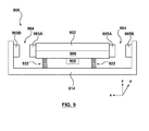
- haptic device 300 includes a plurality of guide rails or cylindrical posts 316 that are slidingly received through holes or openings 318 formed through mounting component 306 in order to provide haptic device 300 with stability during movement of touch screen 302. More particularly, with additional reference to FIG. 4 which shows a perspective view of mounting component 306 and FIG. 5 which shows a perspective view of housing component 314 and posts 316, each post 316 includes a first end 317 and a second or opposing end 319 that is fixed or attached to housing component 314. Posts 316 are sized to be positioned through corresponding openings 318 such that mounting component 306 (and touch screen 302 attached thereto) are slidingly disposed over posts 316.
- “Slidingly disposed” as used herein means that mounting component 306 (and touch screen 302 attached thereto) are disposed over posts 316 and are configured to slide or move relative to posts 316.
- mounting component 306 (and touch screen 302 attached thereto) is moved along the z-axis and the mounting component (and touch screen 302 attached thereto) slides up and down along posts 316 such that the posts serve as a track or guide for movement of the touch screen along the z-axis.
- openings 318 are sized only slightly larger than posts 316 in order to further limit or restrict side to side movement of touch screen 302 along the x- axis and/or along the y- axis.
- posts 316 are not required components of the haptic device, posts 316 are configured to assist magnetic suspension systems 304 in restricting side-to-side movement of touch screen 302 along the x- axis and/or along the y- axis.
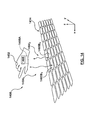
- FIG. 9 is a side view of a haptic device 900 according to another embodiment hereof, the haptic device including magnetic suspension systems 904 for suspending a touch screen 902 beside or within a housing or base component 914 along the x-axis.
- Magnetic suspension systems 904 couple touch screen 902 and housing component 914 together such that the touch screen is movable relative to the housing component along the x-axis.
- Magnetic suspension systems 904 are shown in their nominal configurations with no force applied thereto.
- each magnetic suspension system 904 includes a first programmable magnet 905A attached to touch screen 902 and a second programmable magnet 905B attached to housing component 914.
- First and second programmable magnets 905A, 905B are each programmable magnets including multiple magnetic elements of various strength and polarity on a single substrate.
- the forces produced or output by haptic actuator 908 onto touch screen 902 are linear and along the x-axis, parallel to the planar surface of the touch screen 902.
- First and second programmable magnets 905A, 905B are programmed to attract and repel each other with a programmed force at the same time such that touch screen 902 is "suspended" magnetically beside or within housing component 914 such that the touch screen floats beside or within the housing component with a programmed spring force or damping.
- magnetic suspension systems in accordance with embodiments hereof are configured to or programmed such that touch screen 902 floats or hovers a controlled or programmed spaced-apart distance from housing component 914 in a nominal configuration shown in FIG.
- magnetic suspension systems 904 are configured or programmed to allow movement of touch screen 902 in the direction of the x-axis. Although not shown herein, magnetic suspension systems may be configured to allow preferential movement along the y- axis as well.
- spring elements 922 are utilized as a mechanical suspension system in haptic device 900 to couple touch screen 902 to housing component 914 and allow touch screen 902 to be moved along the z-axis.
- Spring elements 922 are shown as helical or coiled elements, but may be a compliant material such as rubber, foam, or flexures.
- another magnetic suspension system such as magnetic suspension system 304 may be utilized as a suspension system to couple touch screen 902 to housing component 914 and allow touch screen 902 to be moved along the z-axis.
- magnetic suspension systems 904 that are configured or programmed to allow movement of touch screen 902 in the direction of the x-axis may also be programmed or configured to suspend or float touch screen 902 above the housing component 914 in the direction of the z-axis and allow movement of touch screen 902 in the direction of the z-axis.
- magnetic suspension systems such as those described above may be utilized in other haptic applications to magnetically suspend a moving component relative to a fixed housing component with a programmed spring force or damping.
- magnetic suspension systems such as those described above may be utilized to magnetically suspend a user input device of a handheld gaming controller 1024 for a gaming system such as the one shown in FIGS. 10A-10B .
- the controller is merely an exemplary embodiment of a haptic peripheral and that haptic peripherals with other configurations, shapes, and sizes may be used such as, but not limited to, phones, personal digital assistants (PDA), tablets, computers, gaming peripherals, and other controllers for virtual reality systems known to those skilled in the art.
- PDA personal digital assistants
- FIGS. 10A and 10B are different perspective views of controller 1024.
- a housing 1034 of controller 1024 is shaped to easily accommodate two hands gripping the device, either by a left-handed user or a right-handed user.
- controller 1024 is merely an exemplary embodiment of a controller of similar shape and size to many "gamepads" currently available for video game console systems, and that controllers with other configurations of user input elements, shapes, and sizes may be used, including but not limited to controllers such as a WiiTM remote or WiiTM U Controller, Sony® SixAxisTM controller or Sony® Wand controller, an XboxTM controller or similar controller, as well as controllers shaped as real life objects (such as tennis rackets, golf clubs, baseball bats, and the like) and other shapes.
- controllers such as a WiiTM remote or WiiTM U Controller, Sony® SixAxisTM controller or Sony® Wand controller, an XboxTM controller or similar controller, as well as controllers shaped as real life objects (such as tennis rackets, golf
- Controller 1024 includes several user input elements or manipulandums, including a joystick 1030, buttons 1032, and triggers 1036.
- user input element refers to an interface device such as a trigger, button, joystick, or the like, which is manipulated by the user to interact with ahost computer (not shown).
- controller 1024 may include one or more haptic actuators (not shown) to drive the user input elements as well as one or more general or rumble actuators 1026, 1028 coupled to housing 1034 in a location where a hand of the user is generally located. Such haptic actuators provide haptic feedback to the user relating to operation of the video game.
- Each magnetic suspension system 1004 includes a first programmable magnet 1005A (which when assembled is attached to trigger 1036 as will be described in more detail with respect to FIGS. 12-13 ) and a second programmable magnet 1005B which is a non-moving part housed within controller 1024.
- First and second programmable magnets 1005A, 1005B are each programmable magnets including multiple magnetic elements of various strength and polarity on a single substrate.
- First programmable magnet 1005A has a triangular configuration that includes a base face or surface 1042, as well as two opposing angular faces or surfaces 1038, 1040.
- first programmable magnet 1005A rotates or pivots around a pivot point 1044, which is formed between opposing angular surfaces 1038, 1040 thereof, as indicated by directional arrow 1048 shown on FIG. 11 .
- FIGS. 12-13 are schematic illustrations of a portion of controller 1024 with housing 1034 removed (a portion of housing 1034 is shown in phantom) to illustrate the structural relationship between trigger 1024 and magnetic suspension system 1004.
- FIG. 13 illustrates a nominal configuration of magnetic suspension system 1004 and trigger 1024 in which no force is applied to trigger 1024.
- Trigger 1036 protrudes outside of or extends away from housing 1034, and base surface 1042 of first programmable magnet 1005A faces or opposes second programmable magnet 1005B.
- Base surface 1042 of first programmable magnet 1005A and second programmable magnet 1005B are programmed to attract and repel each other with a programmed force at the same time such that trigger 1024 is magnetically "suspended" in the nominal configuration with trigger 1024 protruding outside of or extending away from housing 1034 with a programmed spring force or damping.
- magnetic suspension system 1004 in accordance with embodiments hereof are configured to or programmed such that first programmable magnet 1005A is suspended or positioned a controlled or programmed spaced-apart distance from second programmable magnet 1005B.
- trigger 1036 and first programmable magnet 1005A attached thereto rotate or pivot around pivot point 1044 until angular surface 1040 of first programmable magnet 1005A faces or is adjacent to second programmable magnet 1005B as shown in FIG. 12 .
- the downward force applied to trigger 1036 may be user-applied (e.g., trigger 1036 is manually rotated with respect to housing 1034 and the trigger is pressed into the controller housing by the user during video game operation to input user action) or may be applied by a haptic actuator (not shown) housed within controller 1024 for providing haptic effects to the user during video game operation.
- Angular surface 1040 and/or angular surface 1038 of first programmable magnet 1005A are programmed to attract second programmable magnet 1005B.
- the attraction force between angular surface 1040 and/or angular surface 1038 of first programmable magnet 1005A and second programmable magnet 1005B causes first programmable magnet 1005A (and trigger 1036 attached thereto) to move towards second programmable magnet 1005B, thereby causing first programmable magnet 1005A (and trigger 1036 attached thereto) to return to their nominal configuration shown in FIG. 13 .
- the attraction force between angular surface 1040 and/or angular surface 1038 of first programmable magnet 1005A and second programmable magnet 1005B thus essentially is a controlled or programmed spring force such that trigger 1036 returns to the nominal configuration when no force is applied thereto.
- FIG. 14 is a perspective view illustration of a haptic system 1400 including a haptic device 1452 according to another embodiment hereof, the haptic device being a wearable component that utilizes at least one magnetic suspension system for suspending the wearable component above a fixed base component 1414 along the z-axis.
- Wearable haptic device 1452 includes at least a first programmable magnet 1405A and a haptic actuator 1408 attached thereto for producing haptic effects.
- FIG. 14 is a perspective view illustration of a
- fixed base component 1414 includes a plurality of second programmable magnets 1405B 1 , 1405B 2 which each form or create an individual or discrete magnetic suspension system 1404 1 , 1404 2 , respectively, with programmed or programmed characteristics.
- Programmable magnets 1405A, 1405B 1 , 1405B 2 are each programmable magnets including multiple magnetic elements of various strength and polarity on a single substrate.
- each magnetic suspension system includes first and second programmable magnets that are programmed to attract and repel with a programmed force at the same time such that wearable haptic device 1452 is "suspended" magnetically above fixed base component 1414 such that the wearable haptic device floats above the fixed base component with a programmed spring force or damping.
- magnetic suspension systems in accordance with embodiments hereof are configured or formed to such that wearable haptic device 1452 floats or hovers a controlled or programmed spaced-apart distance from fixed base component 1414 in a nominal configuration shown in FIG.
- first programmable magnet 1405A attached to the wearable haptic device
- second programmable magnet opposes or faces first programmable magnet 1405A.
- Each magnetic suspension system 1404 1 , 1404 2 is configured to have pre-programmed patterns of suspension and spring force characteristics.
- magnetic suspension system 1404 1 is programmed to suspend wearable haptic device 1452 a first controlled or programmed spaced-apart distance from fixed base component 1414 and is programmed to allow movement between wearable haptic device 1452 and fixed base component 1414 in reaction to a force applied to the wearable component by haptic actuator 1008 with a first controlled or programmed spring force.
- magnetic suspension system 1404 2 is programmed to suspend wearable haptic device 1452 a second controlled or programmed spaced-apart distance from fixed base component 1414 and is programmed to allow movement between wearable haptic device 1452 and fixed base component 1414 in reaction to a force applied to the wearable component by haptic actuator 1008 with a second controlled or programmed spring force.
- the first and second controlled or programmed spaced-apart distances may be different values or may be the same, depending upon application, and the first and second controlled or programmed spring force may be different values or may be the same, depending upon application.
- haptic system 1400 may utilize any number of magnetic suspension systems and the magnetic suspension systems may be configured or programmed with the same characteristics or with different characteristics as described above.
Abstract
Description
- The present invention relates generally to components and/or systems which provide haptic feedback to the user, and more particularly to touch screens and touch surfaces which provide haptic feedback to the user.
- New generation consumer devices increasingly rely on touch screen inputs such as virtual buttons and sliders displayed on a screen as an alternative to physical inputs. Users may interface with such devices almost exclusively by touching and/or otherwise manipulating the virtual buttons, sliders, scrollers, and the like on the screen with one or more finger(s). Graphic displays on the screen provide visual feedback responsive to such manipulation. In some more recent touch screen devices, force feedback or tactile feedback, commonly collectively known as haptic feedback, can also be provided to a user as the user's fingers interact with virtual objects on the touch screen. This is accomplished generally by moving or vibrating the screen with a haptic actuator coupled to the screen.
- To allow the haptic touch screen to move in response to the haptic actuator and thereby to isolate a haptic effect to the screen, haptic touch screens have been compliantly suspended within electronic devices in which they reside. It is important, however, that, even though the screen must be able to move when the haptic actuator is activated, the suspended screen must nevertheless feel to a user as if it were substantially rigidly mounted when touched. Others have addressed the problem by not using a suspension, but not using a suspension limits the mass of the system that can have haptic effects.
- Suspensions utilizing compliant grommet for mounting touch screens and touch surfaces within a housing are known, as illustrated in
U.S. Patent No. 8,629,954 to Olien et al. , herein incorporated by reference in its entirety. More particularly,FIG. 1 reproduced from Olien et al. illustrates an exploded view of various components of an electronictouch screen system 100 for providing haptic feedback to atouch screen 102 that utilizes a plurality ofgrommet suspension elements 104 in a mechanical suspension system. In addition totouch screen 102,touch screen system 100 includes acarrier 106, a motor orhaptic actuator 108, adust seal 110, anLCD component 112, and amain housing component 114.Grommet suspension elements 104 are configured to allow preferential movement oftouch screen 102 along a certain axis, such as along an x- axis, while limiting movement in other directions, such as along a y- axis or a z- axis. - In addition to compliant grommet components, other suspensions have been proposed for touch screen applications as illustrated in
U.S. Patent No. 8,059,105 to Rosenberg et al. , herein incorporated by reference in its entirety, andU.S. Patent Pub. No. 2010/0245254 A1 to Olien et al, herein incorporated by reference in its entirety.FIG. 2 , which is reproduced from Rosenberg et al., illustrates atouch screen system 200 having one ormore spring elements 204 coupled between a touchpad ortouch screen 202 and amain housing component 214.Spring elements 204 are shown as helical or coiled elements, but may be a compliant material such as rubber, foam, or flexures.Spring elements 204couple touch screen 202 to therigid housing 214 ofsystem 200 and allowtouch screen 202 to be moved along the z-axis. In the embodiment ofFIG. 2 , one or morepiezoelectric actuators 208 are coupled to the underside of atouch screen 202 and serve to output a small pulse, vibration, or texture sensation ontotouch screen 202 and to the user if the user is contacting the touch screen. - A need exists in the art for improved and/or alternative suspension systems for haptic touch screens.
- Embodiments hereof are directed to a haptic device including a first body, a second body, a haptic actuator for moving the second body relative to the first body and thereby provide a haptic effect to a user of the second body, and at least one magnetic suspension system that couples the first and second bodies together such that the second body is movable relative to the first body. The magnetic suspension system includes a first programmable magnet coupled to the first body and a second programmable magnet coupled to the second body. The first and second programmable magnets are configured to simultaneously repel and attract each other in a nominal configuration such that the second body is suspended a programmed spaced-apart distance from the first body. The first and second programmable magnets are also configured to allow movement between the first body and the second body in reaction to a force applied to the second body by the haptic actuator in at least a first direction with a programmed spring force such that the first and second bodies return to the nominal configuration when no force is applied to the second body.
- According to another embodiment hereof, a haptic device has a magnetic suspension system includes a housing component, a touch screen, a haptic actuator for moving the touch screen relative to the housing component and thereby provide a haptic effect to a user of the touch screen, and at least one magnetic suspension system that couples the touch screen and housing components together such that the touch screen is movable relative to the housing component. The magnetic suspension system includes a first programmable magnet coupled to the housing component and a second programmable magnet coupled to the touch screen. The first and second programmable magnets are configured to simultaneously repel and attract each other in a nominal configuration such that the touch screen is suspended a programmed spaced-apart distance from the housing component. The first and second programmable magnets are also configured to allow movement between the housing component and the touch screen in reaction to a force applied to the touch screen by the haptic actuator in at least a first direction with a programmed spring force such that the touch screen and housing component return to the nominal configuration when no force is applied to the touch screen. According to another embodiment hereof, the at least one magnetic suspension system is configured to restrict movement between the housing component and touch screen in a second direction, the first direction and the second direction opposing each other and extending along the z-axis of the magnetic suspension system. Further it is possible that the at least one magnetic suspension system is configured to allow movement between the housing component and touch screen in a second direction, the first direction and the second direction opposing each other and extending along the z-axis of the magnetic suspension system. Furthermore, it is possible that the haptic device comprises at least one post extending between the housing component and touch screen, the touch screen including an opening sized to receive the post such that the touch screen is slidingly disposed over the post. According to one embodiment, the opening is sized only slightly larger than the post in order to restrict movement between the housing component and touch screen in at least a second direction, the first direction and the second direction extending along first and second axes, respectively, of the magnetic suspension system.
- According to another embodiment hereof, a haptic device includes a housing component, a trigger rotatable with respect to the housing component, and at least one magnetic suspension system including a first programmable magnet coupled to the housing component and a second programmable magnet coupled to the trigger. The first and second programmable magnets are configured to simultaneously repel and attract each other in a nominal configuration such that the trigger is suspended a programmed spaced-apart distance from the housing component. The first and second programmable magnets are also configured to allow rotation of the trigger with respect to the housing component in at least a first direction with a programmed spring force such that the trigger returns to the nominal configuration when no force is applied to the trigger.
- The foregoing and other features and advantages of the invention will be apparent from the following description of embodiments thereof as illustrated in the accompanying drawings. The accompanying drawings, which are incorporated herein and form a part of the specification, further serve to explain the principles of the invention and to enable a person skilled in the pertinent art to make and use the invention. The drawings are not to scale.
-
FIG. 1 is an exploded perspective view illustrating various components of a prior art haptic device for providing haptic feedback, wherein grommets are utilized for suspension. -
FIG. 2 is a side view of a prior art haptic device for providing haptic feedback, wherein springs are utilized for suspension. -
FIG. 3 is a side view of a haptic device according to an embodiment hereof, the haptic device including a plurality of magnetic suspension systems for suspending a touch screen above a housing component along the z-axis, wherein the magnetic suspension systems are shown in their nominal configurations with no force applied thereto. -
FIG. 4 is a perspective view of a carrier component of the haptic device ofFIG. 3 , the carrier component being removed from the haptic device for illustration purposes only. -
FIG. 5 is a perspective view of the housing component of the haptic device ofFIG. 3 and a plurality of posts attached to the housing component, the housing component being removed from the haptic device for illustration purposes only. -
FIG. 6A is a perspective view of a conventional magnet. -
FIG. 6B is a perspective view of a programmable magnet. -
FIG. 7 is a side view of the haptic device ofFIG. 3 , wherein an actuator of the haptic device applies a downward force to the touch screen along the z-axis. -
FIG. 8 is a side view of the haptic device ofFIG. 3 , wherein an actuator of the haptic device applies an upward force to the touch screen along the z-axis. -
FIG. 9 is a side view of a haptic device according to another embodiment hereof, the haptic device including magnetic suspension systems for suspending a touch screen beside a housing component along the x-axis, wherein the magnetic suspension systems are shown in their nominal configurations with no force applied thereto. -
FIG. 10A is a perspective view of a controller, the controller including a magnetic suspension system for suspending a user input element thereof according to another embodiment hereof. -
FIG. 10B is another perspective view of the controller ofFIG. 10A . -
FIG. 11 is a side view of a magnetic suspension system to be utilized for suspending the trigger of the controller ofFIGS. 10A and 10B . -
FIG. 12 is a side view of the magnetic suspension system ofFIG. 11 utilized with the trigger of the controller ofFIGS. 10A and 10B , wherein a downward force is applied to the trigger. -
FIG. 13 is a side view of the magnetic suspension system ofFIG. 11 utilized with the trigger of the controller ofFIGS. 10A and 10B , wherein the magnetic suspension system is shown in its nominal configurations with no force applied thereto. -
FIG. 14 is a perspective view illustration of a haptic device according to another embodiment hereof, the haptic device being a wearable component including a magnetic suspension system for suspending the wearable component above a fixed base component along the z-axis. - Specific embodiments of the present invention are now described with reference to the figures, wherein like reference numbers indicate identical or functionally similar elements. The following detailed description is merely exemplary in nature and is not intended to limit the invention or the application and uses of the invention. Although descriptions of embodiments hereof are in the context of a suspension system for an electronic touch screen, the invention may also be used in any other applications where it is deemed useful. Furthermore, there is no intention to be bound by any expressed or implied theory presented in the preceding technical field, background, brief summary or the following detailed description.
- Embodiments hereof are directed to a magnetic suspension system for mounting touch screens and touch surfaces. The magnetic suspension system will be described below within the context of a touch screen wherein a graphical display is disposed behind a touch surface or touch element. It will be understood, however, that the invention is not limited to suspensions for such touch screens but is equally applicable to any haptically excited touch surface or touch element. For example, the suspension system might be applied to suspend the touch pad of a computer wherein the display screen is not co-located with the touch pad. It may be applied to suspend a touch element with at least one touch sensitive region or an array of touch sensitive regions that may be created by capacitive sensors, near field effect sensors, piezo sensors, or other sensor technology. The graphical element may be a display located behind or in a separate location from the touch element and updated by a host computer, or it may simply be a plastic surface with features (e.g., graphics) indicating touch sensitive regions of an associated touch element. Thus, the term touch screen when used in the following detailed description and in the claims should be construed to encompass traditional touch screens as well as any touch surface or touch element and associated graphical element to which haptic effects may be applied.
- Embodiments hereof are directed to a haptic device having a magnetic suspension system. More particularly,
FIG. 3 illustrates ahaptic device 300 that includes a touch surface orscreen 302, a housing orbase component 314, ahaptic actuator 308 for providing a haptic effect to a user oftouch screen 302, and a plurality ofmagnetic suspension systems 304 thatcouple touch screen 302 andhousing component 314 together such that the touch screen is movable relative to the housing component. A carrier or mountingcomponent 306 is coupled to an underside surface oftouch screen 302. For purposes of this disclosure, aftertouch screen 302 is attached to mountingcomponent 306, the mountingcomponent 306 may be considered an integral element or component of the touch screen. Carrier or mountingcomponent 306 is formed from a sheet metal such as steel or aluminum, or a plastic material such as polycarbonate or PC-ABS.Main housing 314 is generally considered to be a compartment or casing, but may be any type of base component. In an embodiment,haptic device 300 is a medical device with a seven inch touch screen display, for instance. In another embodiment,haptic device 300 is an automobile console panel with a control touchpad or touch screen.Haptic device 300 may be any of a number of devices having an automotive interface (i.e., touch screen, touch pad, or touch panel) such as, for instance, a computer, cellular telephone, PDA, portable gaming device, media player, a printer, an office telephone, or the like.Haptic actuator 308 is coupled to an underside surface of mountingcomponent 306, and is thereby coupled totouch screen 302, and may be any of a number of known actuator types including, without limitation, a piezo actuator, voice coil actuator, an eccentric mass actuator, an E-core type actuator, a solenoid, a moving magnet actuator, or other type of actuator as desired. It will be understood by one of ordinary skill in the art that the placement ofhaptic actuator 308 may vary from that shown and is not limited to the location shown inFIG. 3 . Software is used to provide haptic feedback to the user ofhaptic device 300. In an embodiment,touch screen 302 can display a graphical environment based on application programs and/or operating systems that are running, such as a graphical user interface (GUI). The graphical environment may include, for example, backgrounds, windows, data listings, a cursor, icons such as buttons, and other graphical objects well known in GUI environments. A user interacts withhaptic device 300 by touching various regions oftouch screen 302 to activate, move, flip, advance, or otherwise manipulate the virtual graphical objects displayed on the screen, and thereby to provide inputs to the device. Such touch screens and GUIs are well known, as exemplified inU.S. Patent No. 8,059,105 to Rosenberg et al . incorporated by reference above. Although not shown,haptic device 300 may also include an LCD component (not shown) fixed tomain housing component 314 in any suitable manner with a dust seal (not shown) installed to prevent dust intrusion betweentouch screen 302 and the LCD component. - In the embodiment of
FIG. 3 , four discrete but identicalmagnetic suspension systems 304couple touch screen 302 andhousing component 314 at the corners of the haptic device but it will be understood by those of ordinary skill in the art that more magnetic suspension systems may be utilized, or less magnetic suspension system may be utilized. For example, in another embodiment hereof (not shown), the haptic device may include a plurality of discrete magnetic suspension systems extending betweentouch screen 302 andhousing component 314 at strategic locations such as but not limited along a centerline of the haptic device, along one or more edges of the haptic device, and/or adjacent to haptic actuator(s). In yet another embodiment hereof (not shown), only one magnetic suspension system may extend continuously under all or a portion of touch screen. -
Touch screen 302 ofhaptic device 300 may be considered a haptic touch screen in that it is provided withhaptic actuator 308 and associated control hardware and software that provide signals to the actuator causing it to induce desired motion oftouch screen 302 in coordination with the user's touches. A signal may be provided to, for example, induce a jolt in conjunction with a virtual button press or collisions between virtual elements, or vibrations in conjunction with movement of virtual elements across the screen, or other types of screen movements as described in more detail inU.S. Patent No. 8,059,105 to Rosenberg et al . incorporated by reference above. Such haptic feedback or effects, also known as tactile feedback, touch feedback, and vibro-tactile feedback, allows for a more intuitive, engaging, and natural experience for the user ofhaptic device 300 and thus interaction between the user andhaptic device 300 is considerably enhanced through the tactile feedback provided by the haptic effects. - In this embodiment, the forces produced or output by
actuator 308 ontotouch screen 302 are linear and along the z-axis, which is perpendicular or normal to the planar surface of thetouch screen 302. In order to allow a user to feel the forces produced or output byactuator 308,magnetic suspension systems 304 in accordance with embodiments hereof are installed to allowtouch screen 302 to have the required compliance for haptic feedback and be moved by the forces output byactuator 308. However, when the user applies forces totouch screen 302 during operation thereof, allowing movement or travel of the touch screen in other directions may feel fragile or instable to the user. Stated another way, although it is desirable to allow movement of the touch screen during haptic feedback, it is not desirable to allow movement of the touch screen during user operation or control thereof. In order to provide a desired haptic effect, magnetic suspension systems in accordance with embodiments hereof are configured to allow preferential movement oftouch screen 302 with respect tohousing component 314 in a certain direction or along a certain translational axis, such as an z- direction or axis, while limiting or restricting movement in other directions or along other translational axis, such as the y- direction or axis and x- direction or axis, when installed withinhaptic device 300. With reference to the coordinate system shown inFIG. 3 ,magnetic suspension systems 304 are shown configured to allow travel oftouch screen 302 in the direction of the z-axis and to limit or restrict travel in the direction of the y-axis and/or x-axis. In other embodiments hereof, as will be described in more detail below,magnetic suspension systems 304 is programmed or configured to allow travel oftouch screen 302 in a direction of the y-axis and/or x-axis, and/or to limit or restrict travel in the direction of the z-axis to allow a touch screen to move in the direction of the desired haptic effect but be very rigid in other directions. - Each
magnetic suspension system 304 includes a firstprogrammable magnet 305A attached to touch screen 302 (via mounting component 306) and a secondprogrammable magnet 305B attached tohousing component 314. First and secondprogrammable magnets conventional magnet 605A is shown inFIG. 6A while an exemplaryprogrammable magnet 605B is shown inFIG. 6B .Conventional magnet 605A is a single or individual magnetic element having a singular polarity and strength, whileprogrammable magnet 605B includes a plurality ofmagnetic elements 607 of various strength and polarity. When a pair of programmable magnets oppose or face each other such that the magnetic elements thereon oppose or face each other, the corresponding opposing magnetic elements form pre-programmed correlated patterns designed to achieve a desired behavior. The programmable behavior is achieved by creating multipole structures comprising multiple magnetic elements of varying size, location, orientation, and saturation. The exemplary embodiment ofFIG. 6B illustrates a programmable magnet having sixty-sixmagnetic elements 607 on a single or individual surface or substrate, although the particular number of magnetic elements is exemplary and for use of illustration only and may be varied according to application. Eachmagnetic element 607 has the same strength and polarity inFIG. 6B , but the magnetic strength and polarity of anymagnetic element 607 can each be varied to achieve a desired behavior. Thus, programmable magnets are programmable in the sense that the magnetic strength and polarity of anymagnetic element 607 is designed or selected in order to achieve a desired behavior. However, the programmable aspect or nature of the magnet is complete after the programmable magnet is formed with a plurality ofmagnetic elements 607 of various strength and polarity, and thus the programmable magnets may be considered to be "one-time" programmable magnets. Programmable magnets are commercially available from Correlated Magnetics Research LLC of Huntsville, AL. - Referring back to
FIG. 3 , first and secondprogrammable magnets touch screen 302 is "suspended" magnetically abovehousing component 314 such that the touch screen floats above the housing component with a programmed spring force or damping. As such,magnetic suspension systems 304 are configured to or programmed such thattouch screen 302 floats or hovers a controlled or programmed spaced-apart distance fromhousing component 314 in a nominal configuration.Magnetic suspension systems 304 are also configured or programmed to allow movement betweenhousing component 314 andtouch screen 302 in reaction to a force applied to the touch screen byhaptic actuator 308 with a controlled or programmed spring force such thathousing component 314 andtouch screen 302 return to the nominal configuration when no force is applied totouch screen 302. The nominal configuration ofhaptic device 300 is shown inFIG. 3 , withtouch screen 302 being suspended a controlled or programmed distance DN fromhousing component 314. As used herein, controlled or programmed spaced-apart distance means thattouch screen 302 is located or disposed relative tohousing component 314 such that a space or gap exists between the housing component and touch screen which do not contact or touch each other, and the measurement size of the distance is a programmable feature or characteristic ofmagnetic suspension systems 304. In addition, as used herein, nominal configuration is the relative positions or relationship betweentouch screen 302 andhousing component 314 when no force is applied to either component. Stated another way, the nominal configuration may be considered an equilibrium or zero-force state oftouch screen 302 andhousing component 314. - In the embodiment of
FIG. 3 ,magnetic suspension systems 304 are configured or programmed to allow movement oftouch screen 302 in the direction of the z-axis and to limit or restrict travel in the direction of the y-axis and x-axis. More particularly,touch screen 302 is permitted or allowed to move in opposing directions, i.e., upward and downward, along the z-axis of the magnetic suspensions systems. "Opposing directions" as used herein includes a pair of directions that extend or face away from each other, or extend or face in opposite ways that are 180 degrees from each other. However, when the user applies forces totouch screen 302 along either the x- axis in any direction or the y- axis in any direction,magnetic suspension systems 304 do not allow movement oftouch screen 302 in these directions and as such the user feels as thoughtouch screen 302 is rigidly mounted relative tohousing component 314 ofhaptic device 300. When actuator 308 outputs a force along the z- axis,magnetic suspension systems 304 are programmed or configured to allow both upward and downward movement oftouch screen 302 along the z- axis in order to provide haptic effects to the user. More particularly, whenhaptic actuator 308 outputs a force in a downward direction along the z-axis as indicated bydirectional arrow 720 onFIG. 7 ,magnetic suspension systems 304 allow downward movement oftouch screen 302 such that the distance betweentouch screen 302 andhousing component 314 is reduced or decreased to a shortened distance DS. Shortened distance DS is less than the controlled or programmed distance DN shown in the nominal configuration ofFIG. 3 . When the downward force is no longer applied byhaptic actuator 308,housing component 314 andtouch screen 302 return to the nominal configuration due to the controlled or programmed spring force ofmagnetic suspension systems 304. Similarly, whenhaptic actuator 308 outputs a force in an upward direction along the z-axis as indicated bydirectional arrow 820 onFIG. 8 ,magnetic suspension systems 304 allow upward movement oftouch screen 302 such that the distance betweentouch screen 302 andhousing component 314 is increased to a longer distance DL. Longer distance DL is greater than the controlled or programmed distance DN shown in the nominal configuration ofFIG. 3 . When the upward force is no longer applied byhaptic actuator 308,housing component 314 andtouch screen 302 return to the nominal configuration due to the controlled or programmed spring force ofmagnetic suspension systems 304. Thus,magnetic suspension systems 304 allow a user to feel vibrations, jolts, and similar tactile feedback produced byactuator 308 by permitting movement of the touch screen along the z-axis but also provide stability totouch screen 302 during user operation thereof by restricting or preventing movement of the touch screen along the x- axis and the y-axis. - In another embodiment hereof,
magnetic suspension systems 304 are configured or programmed to such that downward movement oftouch screen 302 along the z- axis, i.e., perpendicular tohaptic device 300 andtouch screen 302, is also restricted in addition to movement along the x- axis and along the y- axis. When a user presses down ontouch screen 302 during operation thereof,magnetic suspension systems 304 are configured to limit or restrict movement oftouch screen 302 relative tohousing component 314 in a first direction along a translation axis of the device, which in this example is in the z- axis, so that the user feels as thoughtouch screen 302 is rigidly mounted withinhousing component 314. However, in reaction to the force produced byactuator 308,magnetic suspension systems 304 are configured to allow movement oftouch screen 302 relative tohousing component 314 in a second or opposing direction along the z- axis. Thus, magnetic suspension systems is programmed to have different stiffnesses in opposing actuation directions in order to restrict movement or travel in a particular or first direction while still allowing for movement in a second or opposing direction. In an embodiment hereof, downward movement oftouch screen 302 along the z- axis is not restricted or restricted as much as movement along the x-axis and along the y- axis. Downward movement oftouch screen 302 along the z- axis is only restricted or limited enough to not feel like the touch screen is moving when pressed, but such downward movement is permitted or allowed during the vibration of the haptic effect. For example, first and secondprogrammable magnets - In the embodiment of
FIG. 3 ,haptic device 300 includes a plurality of guide rails orcylindrical posts 316 that are slidingly received through holes oropenings 318 formed through mountingcomponent 306 in order to providehaptic device 300 with stability during movement oftouch screen 302. More particularly, with additional reference toFIG. 4 which shows a perspective view of mountingcomponent 306 andFIG. 5 which shows a perspective view ofhousing component 314 andposts 316, eachpost 316 includes afirst end 317 and a second or opposingend 319 that is fixed or attached tohousing component 314.Posts 316 are sized to be positioned through correspondingopenings 318 such that mounting component 306 (andtouch screen 302 attached thereto) are slidingly disposed overposts 316. "Slidingly disposed" as used herein means that mounting component 306 (andtouch screen 302 attached thereto) are disposed overposts 316 and are configured to slide or move relative toposts 316. When forces are output byactuator 308, mounting component 306 (andtouch screen 302 attached thereto) is moved along the z-axis and the mounting component (andtouch screen 302 attached thereto) slides up and down alongposts 316 such that the posts serve as a track or guide for movement of the touch screen along the z-axis. In addition, in an embodiment hereof,openings 318 are sized only slightly larger thanposts 316 in order to further limit or restrict side to side movement oftouch screen 302 along the x- axis and/or along the y- axis. Thus, althoughposts 316 are not required components of the haptic device, posts 316 are configured to assistmagnetic suspension systems 304 in restricting side-to-side movement oftouch screen 302 along the x- axis and/or along the y- axis. - Although
magnetic suspension systems 304 are configured to allow preferential movement along the z- axis, magnetic suspension systems according to another embodiment hereof are configured to allow preferential movement in other directions of actuation, such as along the x- axis or the y- axis. More particularly,FIG. 9 is a side view of ahaptic device 900 according to another embodiment hereof, the haptic device includingmagnetic suspension systems 904 for suspending atouch screen 902 beside or within a housing orbase component 914 along the x-axis.Magnetic suspension systems 904couple touch screen 902 andhousing component 914 together such that the touch screen is movable relative to the housing component along the x-axis.Magnetic suspension systems 904 are shown in their nominal configurations with no force applied thereto. A carrier or mountingcomponent 906 is coupled to an underside surface oftouch screen 902. Similar to the embodiment ofFIG. 3 , eachmagnetic suspension system 904 includes a firstprogrammable magnet 905A attached totouch screen 902 and a secondprogrammable magnet 905B attached tohousing component 914. First and secondprogrammable magnets - In this embodiment, however, the forces produced or output by
haptic actuator 908 ontotouch screen 902 are linear and along the x-axis, parallel to the planar surface of thetouch screen 902. First and secondprogrammable magnets touch screen 902 is "suspended" magnetically beside or withinhousing component 914 such that the touch screen floats beside or within the housing component with a programmed spring force or damping. As such, magnetic suspension systems in accordance with embodiments hereof are configured to or programmed such thattouch screen 902 floats or hovers a controlled or programmed spaced-apart distance fromhousing component 914 in a nominal configuration shown inFIG. 9 , while also being configured to allow movement betweenhousing component 914 andtouch screen 902 in reaction to a force applied to the touch screen byhaptic actuator 908 with a controlled or programmed spring force such thathousing component 914 andtouch screen 902 return to the nominal configuration when no force is applied totouch screen 902. In the embodiment ofFIG. 9 ,magnetic suspension systems 904 are configured or programmed to allow movement oftouch screen 902 in the direction of the x-axis. Although not shown herein, magnetic suspension systems may be configured to allow preferential movement along the y- axis as well. - In the embodiment of
FIG. 9 ,spring elements 922 are utilized as a mechanical suspension system inhaptic device 900 to coupletouch screen 902 tohousing component 914 and allowtouch screen 902 to be moved along the z-axis.Spring elements 922 are shown as helical or coiled elements, but may be a compliant material such as rubber, foam, or flexures. In another embodiment (not shown), another magnetic suspension system such asmagnetic suspension system 304 may be utilized as a suspension system to coupletouch screen 902 tohousing component 914 and allowtouch screen 902 to be moved along the z-axis. In yet another embodiment (not shown),magnetic suspension systems 904 that are configured or programmed to allow movement oftouch screen 902 in the direction of the x-axis may also be programmed or configured to suspend or floattouch screen 902 above thehousing component 914 in the direction of the z-axis and allow movement oftouch screen 902 in the direction of the z-axis. - In addition to touch screen surfaces, magnetic suspension systems such as those described above may be utilized in other haptic applications to magnetically suspend a moving component relative to a fixed housing component with a programmed spring force or damping. For example, magnetic suspension systems such as those described above may be utilized to magnetically suspend a user input device of a
handheld gaming controller 1024 for a gaming system such as the one shown inFIGS. 10A-10B . However, those skilled in the art would recognize that the controller is merely an exemplary embodiment of a haptic peripheral and that haptic peripherals with other configurations, shapes, and sizes may be used such as, but not limited to, phones, personal digital assistants (PDA), tablets, computers, gaming peripherals, and other controllers for virtual reality systems known to those skilled in the art. -
FIGS. 10A and 10B are different perspective views ofcontroller 1024. Ahousing 1034 ofcontroller 1024 is shaped to easily accommodate two hands gripping the device, either by a left-handed user or a right-handed user. Those skilled in the art would recognize thatcontroller 1024 is merely an exemplary embodiment of a controller of similar shape and size to many "gamepads" currently available for video game console systems, and that controllers with other configurations of user input elements, shapes, and sizes may be used, including but not limited to controllers such as a Wii™ remote or Wii™ U Controller, Sony® SixAxis™ controller or Sony® Wand controller, an Xbox™ controller or similar controller, as well as controllers shaped as real life objects (such as tennis rackets, golf clubs, baseball bats, and the like) and other shapes.Controller 1024 includes several user input elements or manipulandums, including ajoystick 1030,buttons 1032, and triggers 1036. As used herein, user input element refers to an interface device such as a trigger, button, joystick, or the like, which is manipulated by the user to interact with ahost computer (not shown). Withinhousing 1034,controller 1024 may include one or more haptic actuators (not shown) to drive the user input elements as well as one or more general orrumble actuators housing 1034 in a location where a hand of the user is generally located. Such haptic actuators provide haptic feedback to the user relating to operation of the video game. - Turning now to
FIG. 11 ,magnetic suspension system 1004 to be utilized withincontroller 1024 will be described. Eachmagnetic suspension system 1004 includes a firstprogrammable magnet 1005A (which when assembled is attached to trigger 1036 as will be described in more detail with respect toFIGS. 12-13 ) and a secondprogrammable magnet 1005B which is a non-moving part housed withincontroller 1024. First and secondprogrammable magnets programmable magnet 1005A has a triangular configuration that includes a base face orsurface 1042, as well as two opposing angular faces orsurfaces trigger 1036 is operated, firstprogrammable magnet 1005A rotates or pivots around apivot point 1044, which is formed between opposingangular surfaces directional arrow 1048 shown onFIG. 11 . - When
magnetic suspension system 1004 is utilized withincontroller 1024, firstprogrammable magnet 1005A is attached to trigger 1036 as shownFIGS. 12-13 and secondprogrammable magnet 1005B is housed or positioned withincontroller 1024.FIGS. 12-13 are schematic illustrations of a portion ofcontroller 1024 withhousing 1034 removed (a portion ofhousing 1034 is shown in phantom) to illustrate the structural relationship betweentrigger 1024 andmagnetic suspension system 1004.FIG. 13 illustrates a nominal configuration ofmagnetic suspension system 1004 andtrigger 1024 in which no force is applied to trigger 1024.Trigger 1036 protrudes outside of or extends away fromhousing 1034, andbase surface 1042 of firstprogrammable magnet 1005A faces or opposes secondprogrammable magnet 1005B.Base surface 1042 of firstprogrammable magnet 1005A and secondprogrammable magnet 1005B are programmed to attract and repel each other with a programmed force at the same time such thattrigger 1024 is magnetically "suspended" in the nominal configuration withtrigger 1024 protruding outside of or extending away fromhousing 1034 with a programmed spring force or damping. As such,magnetic suspension system 1004 in accordance with embodiments hereof are configured to or programmed such that firstprogrammable magnet 1005A is suspended or positioned a controlled or programmed spaced-apart distance from secondprogrammable magnet 1005B. - When a downward force is applied to trigger 1036 as indicated by
directional arrow 1050 onFIG. 12 ,trigger 1036 and firstprogrammable magnet 1005A attached thereto rotate or pivot aroundpivot point 1044 untilangular surface 1040 of firstprogrammable magnet 1005A faces or is adjacent to secondprogrammable magnet 1005B as shown inFIG. 12 . The downward force applied to trigger 1036 may be user-applied (e.g.,trigger 1036 is manually rotated with respect tohousing 1034 and the trigger is pressed into the controller housing by the user during video game operation to input user action) or may be applied by a haptic actuator (not shown) housed withincontroller 1024 for providing haptic effects to the user during video game operation.Angular surface 1040 and/orangular surface 1038 of firstprogrammable magnet 1005A are programmed to attract secondprogrammable magnet 1005B. When the downward force represented bydirectional arrow 1050 is removed fromtrigger 1036, the attraction force betweenangular surface 1040 and/orangular surface 1038 of firstprogrammable magnet 1005A and secondprogrammable magnet 1005B causes firstprogrammable magnet 1005A (andtrigger 1036 attached thereto) to move towards secondprogrammable magnet 1005B, thereby causing firstprogrammable magnet 1005A (andtrigger 1036 attached thereto) to return to their nominal configuration shown inFIG. 13 . The attraction force betweenangular surface 1040 and/orangular surface 1038 of firstprogrammable magnet 1005A and secondprogrammable magnet 1005B thus essentially is a controlled or programmed spring force such thattrigger 1036 returns to the nominal configuration when no force is applied thereto. - In another embodiment hereof, magnetic suspension systems such as those described above are utilized in a wearable haptic application to magnetically suspend a wearable haptic actuator relative to a fixed base component with a programmed spring force or damping. More particularly,
FIG. 14 is a perspective view illustration of ahaptic system 1400 including ahaptic device 1452 according to another embodiment hereof, the haptic device being a wearable component that utilizes at least one magnetic suspension system for suspending the wearable component above a fixedbase component 1414 along the z-axis. Wearablehaptic device 1452 includes at least a firstprogrammable magnet 1405A and ahaptic actuator 1408 attached thereto for producing haptic effects. In the embodiment ofFIG. 14 , fixedbase component 1414 includes a plurality of second programmable magnets 1405B1, 1405B2 which each form or create an individual or discrete magnetic suspension system 14041, 14042, respectively, with programmed or programmed characteristics.Programmable magnets 1405A, 1405B1, 1405B2 are each programmable magnets including multiple magnetic elements of various strength and polarity on a single substrate. - More particularly, each magnetic suspension system includes first and second programmable magnets that are programmed to attract and repel with a programmed force at the same time such that wearable
haptic device 1452 is "suspended" magnetically above fixedbase component 1414 such that the wearable haptic device floats above the fixed base component with a programmed spring force or damping. As such, magnetic suspension systems in accordance with embodiments hereof are configured or formed to such that wearablehaptic device 1452 floats or hovers a controlled or programmed spaced-apart distance from fixedbase component 1414 in a nominal configuration shown inFIG. 14 , while also being configured to allow movement between fixedbase component 1414 and wearablehaptic device 1452 in reaction to a force applied to the wearable haptic device by haptic actuator 1008 with a controlled or programmed spring force such that fixedbase component 1414 and wearablehaptic device 1452 return to the nominal configuration when no force is applied to the wearable haptic device. - As wearable
haptic device 1452 is moved or translated over fixedbase component 1414, a magnetic suspension system is formed between firstprogrammable magnet 1405A (attached to the wearable haptic device) and whichever second programmable magnet opposes or faces firstprogrammable magnet 1405A. Each magnetic suspension system 14041, 14042 is configured to have pre-programmed patterns of suspension and spring force characteristics. For example, in an embodiment, when firstprogrammable magnet 1405A is positioned to oppose or face second programmable magnet 1405B1, magnetic suspension system 14041 is programmed to suspend wearable haptic device 1452 a first controlled or programmed spaced-apart distance from fixedbase component 1414 and is programmed to allow movement between wearablehaptic device 1452 and fixedbase component 1414 in reaction to a force applied to the wearable component by haptic actuator 1008 with a first controlled or programmed spring force. When firstprogrammable magnet 1405A is positioned to oppose or face second programmable magnet 1405B2, magnetic suspension system 14042 is programmed to suspend wearable haptic device 1452 a second controlled or programmed spaced-apart distance from fixedbase component 1414 and is programmed to allow movement between wearablehaptic device 1452 and fixedbase component 1414 in reaction to a force applied to the wearable component by haptic actuator 1008 with a second controlled or programmed spring force. The first and second controlled or programmed spaced-apart distances may be different values or may be the same, depending upon application, and the first and second controlled or programmed spring force may be different values or may be the same, depending upon application. Although only two individual or discrete magnetic suspension system 14041, 14042 are described herein, it will be understood by one of ordinary skill in the art thathaptic system 1400 may utilize any number of magnetic suspension systems and the magnetic suspension systems may be configured or programmed with the same characteristics or with different characteristics as described above. - While various embodiments have been described above, it should be understood that they have been presented only as illustrations and examples of the present invention, and not by way of limitation. It will be apparent to persons skilled in the relevant art that various changes in form and detail can be made therein without departing from the spirit and scope of the invention. Thus, the breadth and scope of the present invention should not be limited by any of the above-described exemplary embodiments, but should be defined only in accordance with the appended claims and their equivalents. It will also be understood that each feature of each embodiment discussed herein, and of each reference cited herein, can be used in combination with the features of any other embodiment. All patents and publications discussed herein are incorporated by reference herein in their entirety.
Claims (15)
- A haptic device comprising:a first body and a second body;a haptic actuator for moving the second body relative to the first body and thereby provide a haptic effect to a user of the second body; andat least one magnetic suspension system that couples the first and second bodies together such that the second body is movable relative to the first body, the magnetic suspension system including a first programmable magnet coupled to the first body and a second programmable magnet coupled to the second body,
wherein the first and second programmable magnets are configured to simultaneously repel and attract each other in a nominal configuration such that the second body is suspended a programmed spaced-apart distance from the first body, and
wherein the first and second programmable magnets are also configured to allow movement between the first body and the second body in reaction to a force applied to the second body by the haptic actuator in at least a first direction with a programmed spring force such that the first and second bodies return to the nominal configuration when no force is applied to the second body. - The haptic device of claim 1, wherein the second body includes a touch screen or touch surface component that is attached to the haptic actuator.
- The haptic device of claim 1, wherein the second body is a touch screen and the first body is a housing component.
- The haptic device of claim 1, wherein the second body includes a wearable component that is attached to the haptic actuator or wherein the second body includes a user input device of a peripheral.
- The haptic device of claim 4, wherein the user input device is a trigger.
- The haptic device of claim 1 or 3, wherein the at least one magnetic suspension system is configured to restrict movement between the first and second bodies in a second direction, the first direction and the second direction opposing each other and extending along an axis of the magnetic suspension system.
- The haptic device of claim 1 or 3, wherein the at least one magnetic suspension system is configured to allow movement between the first and second bodies in a second direction, the first direction and the second direction opposing each other and extending along an axis of the magnetic suspension system.
- The haptic device of claim 6 or 7, wherein the axis is the z-axis.
- The haptic device of claim 1 or 3, further comprising:at least one post extending between the first and second bodies, the second body including an opening sized to receive the post such that the second body is slidingly disposed over the post.
- The haptic device of claim 9, wherein the opening is sized only slightly larger than the post in order to restrict movement between the first and second bodies in at least a second direction, the first direction and the second direction extending along first and second axes, respectively, of the magnetic suspension system.
- A haptic device comprising:a housing component;a trigger, the trigger being rotatable with respect to the housing component;at least one magnetic suspension system, the magnetic suspension system including a first programmable magnet coupled to the housing component and a second programmable magnet coupled to the trigger,
wherein the first and second programmable magnets are configured to simultaneously repel and attract each other in a nominal configuration such that the trigger is suspended a programmed spaced-apart distance from the housing component, and
wherein the first and second programmable magnets are also configured to allow rotation of the trigger relative to the housing component in at least a first direction with a programmed spring force such that the trigger returns to the nominal configuration when no force is applied to the trigger. - The haptic device of claim 11, further comprising:a haptic actuator for causing rotation of the trigger relative to the housing component and thereby providing a haptic effect to a user of the trigger.
- The haptic device of claim 11, wherein the second programmable magnet has a triangular configuration that includes a base surface and two opposing angular surfaces with a pivot point formed therebetween.
- The haptic device of claim 13, wherein at least one surface of the second programmable magnet is programmed to simultaneously repel and attract the first programmable magnet such that the trigger is suspended a programmed spaced-apart distance from the housing component.
- The haptic device of claim 14, wherein at least one surface of the second programmable magnet is programmed to attract the first programmable magnet.
Applications Claiming Priority (1)
| Application Number | Priority Date | Filing Date | Title |
|---|---|---|---|
| US14/580,161 US9632582B2 (en) | 2014-12-22 | 2014-12-22 | Magnetic suspension system for touch screens and touch surfaces |
Publications (2)
| Publication Number | Publication Date |
|---|---|
| EP3037923A1 true EP3037923A1 (en) | 2016-06-29 |
| EP3037923B1 EP3037923B1 (en) | 2018-06-27 |
Family
ID=54783513
Family Applications (1)
| Application Number | Title | Priority Date | Filing Date |
|---|---|---|---|
| EP15198223.8A Not-in-force EP3037923B1 (en) | 2014-12-22 | 2015-12-07 | Magnetic suspension system for touch screens and touch surfaces |
Country Status (5)
| Country | Link |
|---|---|
| US (1) | US9632582B2 (en) |
| EP (1) | EP3037923B1 (en) |
| JP (1) | JP2016129013A (en) |
| KR (1) | KR20160076429A (en) |
| CN (1) | CN105718042A (en) |
Cited By (2)
| Publication number | Priority date | Publication date | Assignee | Title |
|---|---|---|---|---|
| US10343061B2 (en) | 2014-12-22 | 2019-07-09 | Immersion Corporation | Haptic actuators having magnetic elements and at least one electromagnet |
| FR3080698A1 (en) * | 2018-04-27 | 2019-11-01 | Commissariat A L'energie Atomique Et Aux Energies Alternatives | DEVICE FOR MAINTAINING A TOUCH SURFACE AND TACTILE INSTALLATION |
Families Citing this family (21)
| Publication number | Priority date | Publication date | Assignee | Title |
|---|---|---|---|---|
| US10282014B2 (en) | 2013-09-30 | 2019-05-07 | Apple Inc. | Operating multiple functions in a display of an electronic device |
| US9726922B1 (en) | 2013-12-20 | 2017-08-08 | Apple Inc. | Reducing display noise in an electronic device |
| US10296123B2 (en) | 2015-03-06 | 2019-05-21 | Apple Inc. | Reducing noise in a force signal in an electronic device |
| US10185397B2 (en) * | 2015-03-08 | 2019-01-22 | Apple Inc. | Gap sensor for haptic feedback assembly |
| US9927905B2 (en) | 2015-08-19 | 2018-03-27 | Apple Inc. | Force touch button emulation |
| JP6511527B2 (en) * | 2015-08-19 | 2019-05-15 | パイオニア株式会社 | Input device |
| US10416811B2 (en) | 2015-09-24 | 2019-09-17 | Apple Inc. | Automatic field calibration of force input sensors |
| CN105607323A (en) * | 2016-01-04 | 2016-05-25 | 京东方科技集团股份有限公司 | Display panel and display device |
| WO2018002028A1 (en) * | 2016-06-27 | 2018-01-04 | Preh Gmbh | Touch-sensitive input device with improved haptic generation |
| US10049536B2 (en) * | 2016-10-04 | 2018-08-14 | Immersion Corporation | Haptic actuator incorporating electropermanent magnet |
| DE102016121425A1 (en) * | 2016-11-09 | 2018-05-09 | Preh Gmbh | Control element with touchpad or touchscreen and magnetic reset |
| US10317998B2 (en) * | 2017-06-26 | 2019-06-11 | Microsoft Technology Licensing, Llc | Flexible magnetic actuator |
| WO2019013044A1 (en) * | 2017-07-10 | 2019-01-17 | シャープ株式会社 | Input device |
| US20190079583A1 (en) * | 2017-09-08 | 2019-03-14 | Immersion Corporation | Haptic Actuation Systems for a Touch Surface |
| DE102018105042A1 (en) * | 2018-03-06 | 2019-09-12 | Preh Gmbh | Touch-sensitive control |
| DE102018108061A1 (en) | 2018-04-05 | 2019-10-10 | Tdk Electronics Ag | Device for generating a haptic feedback |
| US10748389B2 (en) * | 2018-06-15 | 2020-08-18 | Immersion Corporation | Damping for a haptic actuator |
| US10409379B1 (en) * | 2018-06-15 | 2019-09-10 | Immersion Corporation | Haptic actuator assembly having a magnetic pre-load device |
| DE112020002585T5 (en) * | 2019-05-29 | 2022-03-03 | Mitsubishi Electric Corporation | INDICATOR |
| CN113054978B (en) * | 2021-03-16 | 2022-11-25 | 科世达(上海)机电有限公司 | Automobile touch device and touch vibration device thereof |
| CN113709435B (en) * | 2021-09-13 | 2023-06-09 | 四川启睿克科技有限公司 | Suspension laser television |
Citations (4)
| Publication number | Priority date | Publication date | Assignee | Title |
|---|---|---|---|---|
| US20100245254A1 (en) | 2009-03-24 | 2010-09-30 | Immersion Corporation | Planar Suspension Of A Haptic Touch Screen |
| US20110227849A1 (en) * | 2010-03-18 | 2011-09-22 | Immersion Corporation | Grommet Suspension Component and System |
| US8059105B2 (en) | 1998-06-23 | 2011-11-15 | Immersion Corporation | Haptic feedback for touchpads and other touch controls |
| US20140125471A1 (en) * | 2012-11-05 | 2014-05-08 | Advanced Input Devices, Inc. | Haptic feedback systems and methods |
Family Cites Families (74)
| Publication number | Priority date | Publication date | Assignee | Title |
|---|---|---|---|---|
| US3128999A (en) | 1962-09-17 | 1964-04-14 | Lord Mfg Co | Resilient mounting |
| US4556130A (en) | 1982-08-30 | 1985-12-03 | Stanley Puszakowski | Vibration damper and method of making the same |
| US5335893A (en) | 1992-10-23 | 1994-08-09 | The Boeing Company | 360 degree adjustable vibration dampening and thermal isolating bracket |
| US5419626A (en) | 1993-09-01 | 1995-05-30 | Ncr Corporation | Computer housing seal |
| US5765819A (en) | 1994-02-22 | 1998-06-16 | Macrotech Fluid Sealing, Inc. | Vibration isolation grommet |
| US5568357A (en) | 1994-06-15 | 1996-10-22 | Metanetics Corporation | Display support having cradled damping caps for floating core shock absorption |
| US5594574A (en) | 1994-11-30 | 1997-01-14 | Rockwell International Corp. | LCD multi-axis floating mount |
| US5751551A (en) | 1995-11-07 | 1998-05-12 | Sun Microsystems, Inc. | Universal hard drive bracket with shock and vibrational isolation and electrical grounding |
| US5965249A (en) | 1997-08-07 | 1999-10-12 | Gore Enterprise Holdings, Inc. | Vibration damping composite material |
| US6088019A (en) * | 1998-06-23 | 2000-07-11 | Immersion Corporation | Low cost force feedback device with actuator for non-primary axis |
| US6283859B1 (en) | 1998-11-10 | 2001-09-04 | Lord Corporation | Magnetically-controllable, active haptic interface system and apparatus |
| JP2000195370A (en) * | 1998-12-28 | 2000-07-14 | Sony Computer Entertainment Inc | Reaction force generator |
| JP2000250689A (en) * | 1999-03-03 | 2000-09-14 | Minolta Co Ltd | Virtual object presentation system |
| KR100308042B1 (en) | 1999-04-15 | 2001-09-26 | 구자홍 | multiple damping device for speaker system in video display appliance |
| US6822635B2 (en) | 2000-01-19 | 2004-11-23 | Immersion Corporation | Haptic interface for laptop computers and other portable devices |
| US6879318B1 (en) | 2000-10-06 | 2005-04-12 | Industrial Technology Research Institute | Touch screen mounting assembly for LCD panel and method for fabrication |
| KR100474750B1 (en) | 2000-10-13 | 2005-03-10 | 가부시키가이샤 덴소 | Touch panel, display device, and method of manufacturing touch panel |
| DE20019074U1 (en) | 2000-11-09 | 2001-01-18 | Siemens Ag | Mobile electronic device with display and control element |
| US6900984B2 (en) | 2001-04-24 | 2005-05-31 | Apple Computer, Inc. | Computer component protection |
| DE20110595U1 (en) | 2001-06-28 | 2002-08-08 | Siemens Ag | Holding device for floating storage of a flat screen and electronic display device with flat screen and holding device |
| US6975305B2 (en) | 2001-12-07 | 2005-12-13 | Nec Infrontia Corporation | Pressure-sensitive touch panel |
| JP3594586B2 (en) * | 2002-03-08 | 2004-12-02 | Kpe株式会社 | Lever, slot machine and control method thereof |
| JP2003323259A (en) | 2002-05-02 | 2003-11-14 | Nec Corp | Information processing apparatus |
| MXPA03009945A (en) | 2002-11-05 | 2007-04-16 | Lg Electronics Inc | Touch screen mounting assembly for lcd monitor. |
| CA2422265A1 (en) | 2003-03-14 | 2004-09-14 | Handshake Interactive Technologies Inc. | A method and system for providing haptic effects |
| US6882528B2 (en) | 2003-05-15 | 2005-04-19 | Aaeon Technology Inc. | Suspension-type shock-avoiding structure for a hard disk |
| US20050115816A1 (en) | 2003-07-23 | 2005-06-02 | Neil Gelfond | Accepting user control |
| US20060181517A1 (en) | 2005-02-11 | 2006-08-17 | Apple Computer, Inc. | Display actuator |
| US7342573B2 (en) | 2004-07-07 | 2008-03-11 | Nokia Corporation | Electrostrictive polymer as a combined haptic-seal actuator |
| TWI261743B (en) | 2004-08-02 | 2006-09-11 | Asustek Comp Inc | Dynamic absorber system and notebook computer utilizing the same |
| JP4593198B2 (en) | 2004-08-05 | 2010-12-08 | 富士通コンポーネント株式会社 | Touch panel and method for manufacturing touch panel |
| JP4329669B2 (en) | 2004-10-21 | 2009-09-09 | ソニー株式会社 | Electronics |
| JP2006146611A (en) | 2004-11-19 | 2006-06-08 | Fujitsu Component Ltd | Haptic panel device |
| JP5275025B2 (en) | 2005-06-27 | 2013-08-28 | コアクティヴ・ドライヴ・コーポレイション | Synchronous vibrator for tactile feedback |
| JP4697095B2 (en) | 2006-08-29 | 2011-06-08 | ソニー株式会社 | Touch panel display device, electronic device and game device |
| WO2008030594A2 (en) | 2006-09-09 | 2008-03-13 | F-Origin, Inc. | Integrated pressure sensitive lens assembly |
| US7616436B2 (en) | 2007-05-17 | 2009-11-10 | Dell Products L.P. | Systems and methods for mounting components of an information handling system |
| US8072418B2 (en) | 2007-05-31 | 2011-12-06 | Disney Enterprises, Inc. | Tactile feedback mechanism using magnets to provide trigger or release sensations |
| CN101681212A (en) | 2007-06-14 | 2010-03-24 | 诺基亚公司 | Screen assembly |
| US7667371B2 (en) | 2007-09-17 | 2010-02-23 | Motorola, Inc. | Electronic device and circuit for providing tactile feedback |
| KR100896812B1 (en) * | 2007-11-12 | 2009-05-11 | 한국과학기술원 | Haptic module using magnetic force, electronic apparatuses having the module |
| US20100127140A1 (en) | 2008-01-23 | 2010-05-27 | Gary Smith | Suspension for a pressure sensitive touch display or panel |
| CN101515210B (en) * | 2008-02-18 | 2011-11-02 | 联想(北京)有限公司 | Electronic device with touch display structure |
| PL2134148T3 (en) | 2008-06-11 | 2011-12-30 | Advanced Digital Broadcast Sa | Attachment assembly for mounting electronic devices |
| CN101626668B (en) | 2008-07-08 | 2012-09-19 | 鸿富锦精密工业(深圳)有限公司 | Electronic equipment component and fixing device thereof |
| CN101657079B (en) | 2008-08-22 | 2012-11-21 | 鸿富锦精密工业(深圳)有限公司 | Rotating system and fixture with same |
| US20100117809A1 (en) | 2008-11-11 | 2010-05-13 | Motorola Inc. | Display module with piezoelectric haptics |
| US8362882B2 (en) | 2008-12-10 | 2013-01-29 | Immersion Corporation | Method and apparatus for providing Haptic feedback from Haptic textile |
| WO2010104953A1 (en) | 2009-03-10 | 2010-09-16 | Artificial Muscle, Inc. | Electroactive polymer transducers for tactile feedback devices |
| JP5365786B2 (en) | 2009-04-06 | 2013-12-11 | 並木精密宝石株式会社 | Touch panel structure using piezoelectric elements |
| KR101084936B1 (en) | 2009-08-07 | 2011-11-17 | 삼성전기주식회사 | Touch screen device |
| US8390594B2 (en) | 2009-08-18 | 2013-03-05 | Immersion Corporation | Haptic feedback using composite piezoelectric actuator |
| KR101622632B1 (en) | 2009-08-26 | 2016-05-20 | 엘지전자 주식회사 | Mobile terminal |
| US8436806B2 (en) | 2009-10-02 | 2013-05-07 | Research In Motion Limited | Method of synchronizing data acquisition and a portable electronic device configured to perform the same |
| JP2013508913A (en) | 2009-10-19 | 2013-03-07 | バイエル・マテリアルサイエンス・アクチェンゲゼルシャフト | Flex assembly and fixture for tactile feedback |
| US8345410B2 (en) | 2010-01-06 | 2013-01-01 | Apple Inc. | Handheld computing device |
| US8432678B2 (en) | 2010-01-06 | 2013-04-30 | Apple Inc. | Component assembly |
| US8638318B2 (en) | 2010-05-28 | 2014-01-28 | Elo Touch Solutions, Inc. | Multi-layer coversheet for saw touch panel |
| KR101080641B1 (en) | 2010-06-30 | 2011-11-08 | 주식회사 하이소닉 | Portable terminal with haptic module |
| KR101805473B1 (en) * | 2010-10-22 | 2017-12-08 | 한국과학기술원 | Vibration module for portable terminal |
| JP2012108402A (en) | 2010-11-19 | 2012-06-07 | Tdk Corp | Image display device |
| US9054605B2 (en) | 2010-11-19 | 2015-06-09 | Hysonic. Co., Ltd. | Haptic module using piezoelectric element |
| US8279031B2 (en) * | 2011-01-20 | 2012-10-02 | Correlated Magnetics Research, Llc | Multi-level magnetic system for isolation of vibration |
| JP5275384B2 (en) * | 2011-02-17 | 2013-08-28 | 日本電信電話株式会社 | Concrete column vibration device |
| CN202094851U (en) | 2011-04-04 | 2011-12-28 | 瑞声光电科技(常州)有限公司 | Piezoelectric vibrating device |
| US9710061B2 (en) * | 2011-06-17 | 2017-07-18 | Apple Inc. | Haptic feedback device |
| CN102221889B (en) | 2011-06-27 | 2013-05-22 | 瑞声声学科技(深圳)有限公司 | Touch feedback device |
| US8870651B2 (en) * | 2012-05-18 | 2014-10-28 | Universal Entertainment Corporation | Display device for gaming machine and gaming machine including the same |
| US9466783B2 (en) | 2012-07-26 | 2016-10-11 | Immersion Corporation | Suspension element having integrated piezo material for providing haptic effects to a touch screen |
| JP5898774B2 (en) * | 2012-09-13 | 2016-04-06 | 株式会社ソニー・コンピュータエンタテインメント | Force display device |
| US9427898B2 (en) | 2012-11-06 | 2016-08-30 | Taylor Cable Products, Inc. | Apparatus for molding polymers and composite laminates |
| CN103207672B (en) * | 2013-03-04 | 2015-11-25 | 小米科技有限责任公司 | Physical feedback system, control method, device, display assembly and electronic equipment |
| US9174134B1 (en) | 2014-11-12 | 2015-11-03 | Immersion Corporation | Peripheral device with haptic diminishment prevention component |
| US10073523B2 (en) | 2014-12-23 | 2018-09-11 | Immersion Corporation | Position control of a user input element associated with a haptic output device |
-
2014
- 2014-12-22 US US14/580,161 patent/US9632582B2/en not_active Expired - Fee Related
-
2015
- 2015-11-25 KR KR1020150165291A patent/KR20160076429A/en unknown
- 2015-12-07 EP EP15198223.8A patent/EP3037923B1/en not_active Not-in-force
- 2015-12-15 JP JP2015243856A patent/JP2016129013A/en active Pending
- 2015-12-16 CN CN201510940376.5A patent/CN105718042A/en active Pending
Patent Citations (5)
| Publication number | Priority date | Publication date | Assignee | Title |
|---|---|---|---|---|
| US8059105B2 (en) | 1998-06-23 | 2011-11-15 | Immersion Corporation | Haptic feedback for touchpads and other touch controls |
| US20100245254A1 (en) | 2009-03-24 | 2010-09-30 | Immersion Corporation | Planar Suspension Of A Haptic Touch Screen |
| US20110227849A1 (en) * | 2010-03-18 | 2011-09-22 | Immersion Corporation | Grommet Suspension Component and System |
| US8629954B2 (en) | 2010-03-18 | 2014-01-14 | Immersion Corporation | Grommet suspension component and system |
| US20140125471A1 (en) * | 2012-11-05 | 2014-05-08 | Advanced Input Devices, Inc. | Haptic feedback systems and methods |
Cited By (2)
| Publication number | Priority date | Publication date | Assignee | Title |
|---|---|---|---|---|
| US10343061B2 (en) | 2014-12-22 | 2019-07-09 | Immersion Corporation | Haptic actuators having magnetic elements and at least one electromagnet |
| FR3080698A1 (en) * | 2018-04-27 | 2019-11-01 | Commissariat A L'energie Atomique Et Aux Energies Alternatives | DEVICE FOR MAINTAINING A TOUCH SURFACE AND TACTILE INSTALLATION |
Also Published As
| Publication number | Publication date |
|---|---|
| KR20160076429A (en) | 2016-06-30 |
| US9632582B2 (en) | 2017-04-25 |
| JP2016129013A (en) | 2016-07-14 |
| EP3037923B1 (en) | 2018-06-27 |
| CN105718042A (en) | 2016-06-29 |
| US20160179200A1 (en) | 2016-06-23 |
Similar Documents
| Publication | Publication Date | Title |
|---|---|---|
| EP3037923B1 (en) | Magnetic suspension system for touch screens and touch surfaces | |
| US8232969B2 (en) | Haptic feedback for button and scrolling action simulation in touch input devices | |
| JP6426446B2 (en) | Double rigid suspension system | |
| US8416210B2 (en) | Image display that moves physical objects and causes tactile sensation | |
| EP2778855B1 (en) | User interface device | |
| KR200258353Y1 (en) | Haptic feedback for touchpads and other touch controls | |
| JP2016081524A (en) | Haptically enabled deformable device with rigid component | |
| US20160202760A1 (en) | Systems and methods for controlling feedback for multiple haptic zones | |
| Brucker | Technology for Tactile Tangibles |
Legal Events
| Date | Code | Title | Description |
|---|---|---|---|
| PUAI | Public reference made under article 153(3) epc to a published international application that has entered the european phase |
Free format text: ORIGINAL CODE: 0009012 |
|
| AK | Designated contracting states |
Kind code of ref document: A1 Designated state(s): AL AT BE BG CH CY CZ DE DK EE ES FI FR GB GR HR HU IE IS IT LI LT LU LV MC MK MT NL NO PL PT RO RS SE SI SK SM TR |
|
| AX | Request for extension of the european patent |
Extension state: BA ME |
|
| 17P | Request for examination filed |
Effective date: 20161222 |
|
| RBV | Designated contracting states (corrected) |
Designated state(s): AL AT BE BG CH CY CZ DE DK EE ES FI FR GB GR HR HU IE IS IT LI LT LU LV MC MK MT NL NO PL PT RO RS SE SI SK SM TR |
|
| GRAP | Despatch of communication of intention to grant a patent |
Free format text: ORIGINAL CODE: EPIDOSNIGR1 |
|
| INTG | Intention to grant announced |
Effective date: 20171211 |
|
| GRAJ | Information related to disapproval of communication of intention to grant by the applicant or resumption of examination proceedings by the epo deleted |
Free format text: ORIGINAL CODE: EPIDOSDIGR1 |
|
| GRAS | Grant fee paid |
Free format text: ORIGINAL CODE: EPIDOSNIGR3 |
|
| GRAP | Despatch of communication of intention to grant a patent |
Free format text: ORIGINAL CODE: EPIDOSNIGR1 |
|
| GRAA | (expected) grant |
Free format text: ORIGINAL CODE: 0009210 |
|
| INTC | Intention to grant announced (deleted) | ||
| INTG | Intention to grant announced |
Effective date: 20180514 |
|
| AK | Designated contracting states |
Kind code of ref document: B1 Designated state(s): AL AT BE BG CH CY CZ DE DK EE ES FI FR GB GR HR HU IE IS IT LI LT LU LV MC MK MT NL NO PL PT RO RS SE SI SK SM TR |
|
| REG | Reference to a national code |
Ref country code: GB Ref legal event code: FG4D |
|
| REG | Reference to a national code |
Ref country code: AT Ref legal event code: REF Ref document number: 1012876 Country of ref document: AT Kind code of ref document: T Effective date: 20180715 |
|
| REG | Reference to a national code |
Ref country code: IE Ref legal event code: FG4D |
|
| REG | Reference to a national code |
Ref country code: DE Ref legal event code: R096 Ref document number: 602015012688 Country of ref document: DE |
|
| PG25 | Lapsed in a contracting state [announced via postgrant information from national office to epo] |
Ref country code: SE Free format text: LAPSE BECAUSE OF FAILURE TO SUBMIT A TRANSLATION OF THE DESCRIPTION OR TO PAY THE FEE WITHIN THE PRESCRIBED TIME-LIMIT Effective date: 20180627 Ref country code: LT Free format text: LAPSE BECAUSE OF FAILURE TO SUBMIT A TRANSLATION OF THE DESCRIPTION OR TO PAY THE FEE WITHIN THE PRESCRIBED TIME-LIMIT Effective date: 20180627 Ref country code: BG Free format text: LAPSE BECAUSE OF FAILURE TO SUBMIT A TRANSLATION OF THE DESCRIPTION OR TO PAY THE FEE WITHIN THE PRESCRIBED TIME-LIMIT Effective date: 20180927 Ref country code: FI Free format text: LAPSE BECAUSE OF FAILURE TO SUBMIT A TRANSLATION OF THE DESCRIPTION OR TO PAY THE FEE WITHIN THE PRESCRIBED TIME-LIMIT Effective date: 20180627 Ref country code: NO Free format text: LAPSE BECAUSE OF FAILURE TO SUBMIT A TRANSLATION OF THE DESCRIPTION OR TO PAY THE FEE WITHIN THE PRESCRIBED TIME-LIMIT Effective date: 20180927 |
|
| REG | Reference to a national code |
Ref country code: NL Ref legal event code: MP Effective date: 20180627 |
|
| REG | Reference to a national code |
Ref country code: LT Ref legal event code: MG4D |
|
| PG25 | Lapsed in a contracting state [announced via postgrant information from national office to epo] |
Ref country code: GR Free format text: LAPSE BECAUSE OF FAILURE TO SUBMIT A TRANSLATION OF THE DESCRIPTION OR TO PAY THE FEE WITHIN THE PRESCRIBED TIME-LIMIT Effective date: 20180928 Ref country code: RS Free format text: LAPSE BECAUSE OF FAILURE TO SUBMIT A TRANSLATION OF THE DESCRIPTION OR TO PAY THE FEE WITHIN THE PRESCRIBED TIME-LIMIT Effective date: 20180627 Ref country code: LV Free format text: LAPSE BECAUSE OF FAILURE TO SUBMIT A TRANSLATION OF THE DESCRIPTION OR TO PAY THE FEE WITHIN THE PRESCRIBED TIME-LIMIT Effective date: 20180627 Ref country code: HR Free format text: LAPSE BECAUSE OF FAILURE TO SUBMIT A TRANSLATION OF THE DESCRIPTION OR TO PAY THE FEE WITHIN THE PRESCRIBED TIME-LIMIT Effective date: 20180627 |
|
| REG | Reference to a national code |
Ref country code: AT Ref legal event code: MK05 Ref document number: 1012876 Country of ref document: AT Kind code of ref document: T Effective date: 20180627 |
|
| PG25 | Lapsed in a contracting state [announced via postgrant information from national office to epo] |
Ref country code: NL Free format text: LAPSE BECAUSE OF FAILURE TO SUBMIT A TRANSLATION OF THE DESCRIPTION OR TO PAY THE FEE WITHIN THE PRESCRIBED TIME-LIMIT Effective date: 20180627 |
|
| PG25 | Lapsed in a contracting state [announced via postgrant information from national office to epo] |
Ref country code: CZ Free format text: LAPSE BECAUSE OF FAILURE TO SUBMIT A TRANSLATION OF THE DESCRIPTION OR TO PAY THE FEE WITHIN THE PRESCRIBED TIME-LIMIT Effective date: 20180627 Ref country code: SK Free format text: LAPSE BECAUSE OF FAILURE TO SUBMIT A TRANSLATION OF THE DESCRIPTION OR TO PAY THE FEE WITHIN THE PRESCRIBED TIME-LIMIT Effective date: 20180627 Ref country code: PL Free format text: LAPSE BECAUSE OF FAILURE TO SUBMIT A TRANSLATION OF THE DESCRIPTION OR TO PAY THE FEE WITHIN THE PRESCRIBED TIME-LIMIT Effective date: 20180627 Ref country code: AT Free format text: LAPSE BECAUSE OF FAILURE TO SUBMIT A TRANSLATION OF THE DESCRIPTION OR TO PAY THE FEE WITHIN THE PRESCRIBED TIME-LIMIT Effective date: 20180627 Ref country code: RO Free format text: LAPSE BECAUSE OF FAILURE TO SUBMIT A TRANSLATION OF THE DESCRIPTION OR TO PAY THE FEE WITHIN THE PRESCRIBED TIME-LIMIT Effective date: 20180627 Ref country code: IS Free format text: LAPSE BECAUSE OF FAILURE TO SUBMIT A TRANSLATION OF THE DESCRIPTION OR TO PAY THE FEE WITHIN THE PRESCRIBED TIME-LIMIT Effective date: 20181027 Ref country code: EE Free format text: LAPSE BECAUSE OF FAILURE TO SUBMIT A TRANSLATION OF THE DESCRIPTION OR TO PAY THE FEE WITHIN THE PRESCRIBED TIME-LIMIT Effective date: 20180627 |
|
| PG25 | Lapsed in a contracting state [announced via postgrant information from national office to epo] |
Ref country code: ES Free format text: LAPSE BECAUSE OF FAILURE TO SUBMIT A TRANSLATION OF THE DESCRIPTION OR TO PAY THE FEE WITHIN THE PRESCRIBED TIME-LIMIT Effective date: 20180627 Ref country code: SM Free format text: LAPSE BECAUSE OF FAILURE TO SUBMIT A TRANSLATION OF THE DESCRIPTION OR TO PAY THE FEE WITHIN THE PRESCRIBED TIME-LIMIT Effective date: 20180627 Ref country code: IT Free format text: LAPSE BECAUSE OF FAILURE TO SUBMIT A TRANSLATION OF THE DESCRIPTION OR TO PAY THE FEE WITHIN THE PRESCRIBED TIME-LIMIT Effective date: 20180627 |
|
| PGFP | Annual fee paid to national office [announced via postgrant information from national office to epo] |
Ref country code: FR Payment date: 20181226 Year of fee payment: 4 |
|
| REG | Reference to a national code |
Ref country code: DE Ref legal event code: R097 Ref document number: 602015012688 Country of ref document: DE |
|
| PGFP | Annual fee paid to national office [announced via postgrant information from national office to epo] |
Ref country code: DE Payment date: 20181231 Year of fee payment: 4 |
|
| PLBE | No opposition filed within time limit |
Free format text: ORIGINAL CODE: 0009261 |
|
| STAA | Information on the status of an ep patent application or granted ep patent |
Free format text: STATUS: NO OPPOSITION FILED WITHIN TIME LIMIT |
|
| PG25 | Lapsed in a contracting state [announced via postgrant information from national office to epo] |
Ref country code: DK Free format text: LAPSE BECAUSE OF FAILURE TO SUBMIT A TRANSLATION OF THE DESCRIPTION OR TO PAY THE FEE WITHIN THE PRESCRIBED TIME-LIMIT Effective date: 20180627 |
|
| 26N | No opposition filed |
Effective date: 20190328 |
|
| REG | Reference to a national code |
Ref country code: CH Ref legal event code: PL |
|
| PG25 | Lapsed in a contracting state [announced via postgrant information from national office to epo] |
Ref country code: LU Free format text: LAPSE BECAUSE OF NON-PAYMENT OF DUE FEES Effective date: 20181207 Ref country code: SI Free format text: LAPSE BECAUSE OF FAILURE TO SUBMIT A TRANSLATION OF THE DESCRIPTION OR TO PAY THE FEE WITHIN THE PRESCRIBED TIME-LIMIT Effective date: 20180627 Ref country code: MC Free format text: LAPSE BECAUSE OF FAILURE TO SUBMIT A TRANSLATION OF THE DESCRIPTION OR TO PAY THE FEE WITHIN THE PRESCRIBED TIME-LIMIT Effective date: 20180627 |
|
| REG | Reference to a national code |
Ref country code: IE Ref legal event code: MM4A |
|
| REG | Reference to a national code |
Ref country code: BE Ref legal event code: MM Effective date: 20181231 |
|
| PG25 | Lapsed in a contracting state [announced via postgrant information from national office to epo] |
Ref country code: IE Free format text: LAPSE BECAUSE OF NON-PAYMENT OF DUE FEES Effective date: 20181207 |
|
| PG25 | Lapsed in a contracting state [announced via postgrant information from national office to epo] |
Ref country code: BE Free format text: LAPSE BECAUSE OF NON-PAYMENT OF DUE FEES Effective date: 20181231 Ref country code: AL Free format text: LAPSE BECAUSE OF FAILURE TO SUBMIT A TRANSLATION OF THE DESCRIPTION OR TO PAY THE FEE WITHIN THE PRESCRIBED TIME-LIMIT Effective date: 20180627 |
|
| PG25 | Lapsed in a contracting state [announced via postgrant information from national office to epo] |
Ref country code: CH Free format text: LAPSE BECAUSE OF NON-PAYMENT OF DUE FEES Effective date: 20181231 Ref country code: LI Free format text: LAPSE BECAUSE OF NON-PAYMENT OF DUE FEES Effective date: 20181231 |
|
| PG25 | Lapsed in a contracting state [announced via postgrant information from national office to epo] |
Ref country code: MT Free format text: LAPSE BECAUSE OF NON-PAYMENT OF DUE FEES Effective date: 20181207 |
|
| PG25 | Lapsed in a contracting state [announced via postgrant information from national office to epo] |
Ref country code: TR Free format text: LAPSE BECAUSE OF FAILURE TO SUBMIT A TRANSLATION OF THE DESCRIPTION OR TO PAY THE FEE WITHIN THE PRESCRIBED TIME-LIMIT Effective date: 20180627 |
|
| PG25 | Lapsed in a contracting state [announced via postgrant information from national office to epo] |
Ref country code: PT Free format text: LAPSE BECAUSE OF FAILURE TO SUBMIT A TRANSLATION OF THE DESCRIPTION OR TO PAY THE FEE WITHIN THE PRESCRIBED TIME-LIMIT Effective date: 20180627 |
|
| PG25 | Lapsed in a contracting state [announced via postgrant information from national office to epo] |
Ref country code: CY Free format text: LAPSE BECAUSE OF FAILURE TO SUBMIT A TRANSLATION OF THE DESCRIPTION OR TO PAY THE FEE WITHIN THE PRESCRIBED TIME-LIMIT Effective date: 20180627 Ref country code: MK Free format text: LAPSE BECAUSE OF NON-PAYMENT OF DUE FEES Effective date: 20180627 Ref country code: HU Free format text: LAPSE BECAUSE OF FAILURE TO SUBMIT A TRANSLATION OF THE DESCRIPTION OR TO PAY THE FEE WITHIN THE PRESCRIBED TIME-LIMIT; INVALID AB INITIO Effective date: 20151207 |
|
| REG | Reference to a national code |
Ref country code: DE Ref legal event code: R119 Ref document number: 602015012688 Country of ref document: DE |
|
| GBPC | Gb: european patent ceased through non-payment of renewal fee |
Effective date: 20191207 |
|
| PG25 | Lapsed in a contracting state [announced via postgrant information from national office to epo] |
Ref country code: FR Free format text: LAPSE BECAUSE OF NON-PAYMENT OF DUE FEES Effective date: 20191231 Ref country code: DE Free format text: LAPSE BECAUSE OF NON-PAYMENT OF DUE FEES Effective date: 20200701 Ref country code: GB Free format text: LAPSE BECAUSE OF NON-PAYMENT OF DUE FEES Effective date: 20191207 |