EP3012688A1 - Method for producing a three-dimensional structure - Google Patents
Method for producing a three-dimensional structure Download PDFInfo
- Publication number
- EP3012688A1 EP3012688A1 EP15180364.0A EP15180364A EP3012688A1 EP 3012688 A1 EP3012688 A1 EP 3012688A1 EP 15180364 A EP15180364 A EP 15180364A EP 3012688 A1 EP3012688 A1 EP 3012688A1
- Authority
- EP
- European Patent Office
- Prior art keywords
- energy input
- jacket wall
- wall
- input method
- volume
- Prior art date
- Legal status (The legal status is an assumption and is not a legal conclusion. Google has not performed a legal analysis and makes no representation as to the accuracy of the status listed.)
- Granted
Links
- 238000004519 manufacturing process Methods 0.000 title claims abstract description 20
- 238000000034 method Methods 0.000 claims abstract description 95
- 239000000463 material Substances 0.000 claims abstract description 66
- 238000001459 lithography Methods 0.000 claims abstract description 34
- 238000011161 development Methods 0.000 claims abstract description 13
- 238000005253 cladding Methods 0.000 claims abstract description 8
- 239000000758 substrate Substances 0.000 claims description 23
- 238000006116 polymerization reaction Methods 0.000 claims description 13
- 238000010521 absorption reaction Methods 0.000 claims description 12
- 230000005855 radiation Effects 0.000 claims description 5
- 238000001723 curing Methods 0.000 description 8
- 238000010438 heat treatment Methods 0.000 description 4
- 239000007788 liquid Substances 0.000 description 3
- 230000035515 penetration Effects 0.000 description 3
- 238000010276 construction Methods 0.000 description 2
- 238000007667 floating Methods 0.000 description 2
- 230000003287 optical effect Effects 0.000 description 2
- 230000000704 physical effect Effects 0.000 description 2
- 238000011417 postcuring Methods 0.000 description 2
- 238000002360 preparation method Methods 0.000 description 2
- 239000002966 varnish Substances 0.000 description 2
- 238000003848 UV Light-Curing Methods 0.000 description 1
- 235000013405 beer Nutrition 0.000 description 1
- 239000000919 ceramic Substances 0.000 description 1
- 238000012822 chemical development Methods 0.000 description 1
- 238000006243 chemical reaction Methods 0.000 description 1
- 239000002131 composite material Substances 0.000 description 1
- 238000013016 damping Methods 0.000 description 1
- 238000000354 decomposition reaction Methods 0.000 description 1
- 230000001419 dependent effect Effects 0.000 description 1
- 238000000609 electron-beam lithography Methods 0.000 description 1
- 239000011521 glass Substances 0.000 description 1
- 239000002086 nanomaterial Substances 0.000 description 1
- 239000013307 optical fiber Substances 0.000 description 1
- 239000003973 paint Substances 0.000 description 1
- 230000010076 replication Effects 0.000 description 1
- 239000004065 semiconductor Substances 0.000 description 1
- 239000007787 solid Substances 0.000 description 1
- 238000007711 solidification Methods 0.000 description 1
- 230000008023 solidification Effects 0.000 description 1
- 239000000126 substance Substances 0.000 description 1
- 238000012876 topography Methods 0.000 description 1
- 238000009281 ultraviolet germicidal irradiation Methods 0.000 description 1
- -1 viscous Substances 0.000 description 1
- 239000002699 waste material Substances 0.000 description 1
Images


Classifications
-
- B—PERFORMING OPERATIONS; TRANSPORTING
- B29—WORKING OF PLASTICS; WORKING OF SUBSTANCES IN A PLASTIC STATE IN GENERAL
- B29C—SHAPING OR JOINING OF PLASTICS; SHAPING OF MATERIAL IN A PLASTIC STATE, NOT OTHERWISE PROVIDED FOR; AFTER-TREATMENT OF THE SHAPED PRODUCTS, e.g. REPAIRING
- B29C64/00—Additive manufacturing, i.e. manufacturing of three-dimensional [3D] objects by additive deposition, additive agglomeration or additive layering, e.g. by 3D printing, stereolithography or selective laser sintering
- B29C64/10—Processes of additive manufacturing
-
- B—PERFORMING OPERATIONS; TRANSPORTING
- B29—WORKING OF PLASTICS; WORKING OF SUBSTANCES IN A PLASTIC STATE IN GENERAL
- B29C—SHAPING OR JOINING OF PLASTICS; SHAPING OF MATERIAL IN A PLASTIC STATE, NOT OTHERWISE PROVIDED FOR; AFTER-TREATMENT OF THE SHAPED PRODUCTS, e.g. REPAIRING
- B29C33/00—Moulds or cores; Details thereof or accessories therefor
- B29C33/38—Moulds or cores; Details thereof or accessories therefor characterised by the material or the manufacturing process
- B29C33/3842—Manufacturing moulds, e.g. shaping the mould surface by machining
-
- B—PERFORMING OPERATIONS; TRANSPORTING
- B29—WORKING OF PLASTICS; WORKING OF SUBSTANCES IN A PLASTIC STATE IN GENERAL
- B29C—SHAPING OR JOINING OF PLASTICS; SHAPING OF MATERIAL IN A PLASTIC STATE, NOT OTHERWISE PROVIDED FOR; AFTER-TREATMENT OF THE SHAPED PRODUCTS, e.g. REPAIRING
- B29C35/00—Heating, cooling or curing, e.g. crosslinking or vulcanising; Apparatus therefor
- B29C35/02—Heating or curing, e.g. crosslinking or vulcanizing during moulding, e.g. in a mould
- B29C35/08—Heating or curing, e.g. crosslinking or vulcanizing during moulding, e.g. in a mould by wave energy or particle radiation
- B29C35/0805—Heating or curing, e.g. crosslinking or vulcanizing during moulding, e.g. in a mould by wave energy or particle radiation using electromagnetic radiation
-
- B—PERFORMING OPERATIONS; TRANSPORTING
- B29—WORKING OF PLASTICS; WORKING OF SUBSTANCES IN A PLASTIC STATE IN GENERAL
- B29C—SHAPING OR JOINING OF PLASTICS; SHAPING OF MATERIAL IN A PLASTIC STATE, NOT OTHERWISE PROVIDED FOR; AFTER-TREATMENT OF THE SHAPED PRODUCTS, e.g. REPAIRING
- B29C64/00—Additive manufacturing, i.e. manufacturing of three-dimensional [3D] objects by additive deposition, additive agglomeration or additive layering, e.g. by 3D printing, stereolithography or selective laser sintering
- B29C64/10—Processes of additive manufacturing
- B29C64/106—Processes of additive manufacturing using only liquids or viscous materials, e.g. depositing a continuous bead of viscous material
- B29C64/124—Processes of additive manufacturing using only liquids or viscous materials, e.g. depositing a continuous bead of viscous material using layers of liquid which are selectively solidified
- B29C64/129—Processes of additive manufacturing using only liquids or viscous materials, e.g. depositing a continuous bead of viscous material using layers of liquid which are selectively solidified characterised by the energy source therefor, e.g. by global irradiation combined with a mask
- B29C64/135—Processes of additive manufacturing using only liquids or viscous materials, e.g. depositing a continuous bead of viscous material using layers of liquid which are selectively solidified characterised by the energy source therefor, e.g. by global irradiation combined with a mask the energy source being concentrated, e.g. scanning lasers or focused light sources
-
- B—PERFORMING OPERATIONS; TRANSPORTING
- B29—WORKING OF PLASTICS; WORKING OF SUBSTANCES IN A PLASTIC STATE IN GENERAL
- B29C—SHAPING OR JOINING OF PLASTICS; SHAPING OF MATERIAL IN A PLASTIC STATE, NOT OTHERWISE PROVIDED FOR; AFTER-TREATMENT OF THE SHAPED PRODUCTS, e.g. REPAIRING
- B29C64/00—Additive manufacturing, i.e. manufacturing of three-dimensional [3D] objects by additive deposition, additive agglomeration or additive layering, e.g. by 3D printing, stereolithography or selective laser sintering
- B29C64/10—Processes of additive manufacturing
- B29C64/141—Processes of additive manufacturing using only solid materials
- B29C64/153—Processes of additive manufacturing using only solid materials using layers of powder being selectively joined, e.g. by selective laser sintering or melting
-
- B—PERFORMING OPERATIONS; TRANSPORTING
- B29—WORKING OF PLASTICS; WORKING OF SUBSTANCES IN A PLASTIC STATE IN GENERAL
- B29C—SHAPING OR JOINING OF PLASTICS; SHAPING OF MATERIAL IN A PLASTIC STATE, NOT OTHERWISE PROVIDED FOR; AFTER-TREATMENT OF THE SHAPED PRODUCTS, e.g. REPAIRING
- B29C64/00—Additive manufacturing, i.e. manufacturing of three-dimensional [3D] objects by additive deposition, additive agglomeration or additive layering, e.g. by 3D printing, stereolithography or selective laser sintering
- B29C64/20—Apparatus for additive manufacturing; Details thereof or accessories therefor
- B29C64/264—Arrangements for irradiation
- B29C64/268—Arrangements for irradiation using laser beams; using electron beams [EB]
- B29C64/273—Arrangements for irradiation using laser beams; using electron beams [EB] pulsed; frequency modulated
-
- B—PERFORMING OPERATIONS; TRANSPORTING
- B29—WORKING OF PLASTICS; WORKING OF SUBSTANCES IN A PLASTIC STATE IN GENERAL
- B29C—SHAPING OR JOINING OF PLASTICS; SHAPING OF MATERIAL IN A PLASTIC STATE, NOT OTHERWISE PROVIDED FOR; AFTER-TREATMENT OF THE SHAPED PRODUCTS, e.g. REPAIRING
- B29C64/00—Additive manufacturing, i.e. manufacturing of three-dimensional [3D] objects by additive deposition, additive agglomeration or additive layering, e.g. by 3D printing, stereolithography or selective laser sintering
- B29C64/20—Apparatus for additive manufacturing; Details thereof or accessories therefor
- B29C64/264—Arrangements for irradiation
- B29C64/277—Arrangements for irradiation using multiple radiation means, e.g. micromirrors or multiple light-emitting diodes [LED]
- B29C64/282—Arrangements for irradiation using multiple radiation means, e.g. micromirrors or multiple light-emitting diodes [LED] of the same type, e.g. using different energy levels
-
- B—PERFORMING OPERATIONS; TRANSPORTING
- B29—WORKING OF PLASTICS; WORKING OF SUBSTANCES IN A PLASTIC STATE IN GENERAL
- B29C—SHAPING OR JOINING OF PLASTICS; SHAPING OF MATERIAL IN A PLASTIC STATE, NOT OTHERWISE PROVIDED FOR; AFTER-TREATMENT OF THE SHAPED PRODUCTS, e.g. REPAIRING
- B29C64/00—Additive manufacturing, i.e. manufacturing of three-dimensional [3D] objects by additive deposition, additive agglomeration or additive layering, e.g. by 3D printing, stereolithography or selective laser sintering
- B29C64/20—Apparatus for additive manufacturing; Details thereof or accessories therefor
- B29C64/295—Heating elements
-
- B—PERFORMING OPERATIONS; TRANSPORTING
- B29—WORKING OF PLASTICS; WORKING OF SUBSTANCES IN A PLASTIC STATE IN GENERAL
- B29C—SHAPING OR JOINING OF PLASTICS; SHAPING OF MATERIAL IN A PLASTIC STATE, NOT OTHERWISE PROVIDED FOR; AFTER-TREATMENT OF THE SHAPED PRODUCTS, e.g. REPAIRING
- B29C64/00—Additive manufacturing, i.e. manufacturing of three-dimensional [3D] objects by additive deposition, additive agglomeration or additive layering, e.g. by 3D printing, stereolithography or selective laser sintering
- B29C64/40—Structures for supporting 3D objects during manufacture and intended to be sacrificed after completion thereof
-
- B—PERFORMING OPERATIONS; TRANSPORTING
- B33—ADDITIVE MANUFACTURING TECHNOLOGY
- B33Y—ADDITIVE MANUFACTURING, i.e. MANUFACTURING OF THREE-DIMENSIONAL [3-D] OBJECTS BY ADDITIVE DEPOSITION, ADDITIVE AGGLOMERATION OR ADDITIVE LAYERING, e.g. BY 3-D PRINTING, STEREOLITHOGRAPHY OR SELECTIVE LASER SINTERING
- B33Y10/00—Processes of additive manufacturing
-
- B—PERFORMING OPERATIONS; TRANSPORTING
- B33—ADDITIVE MANUFACTURING TECHNOLOGY
- B33Y—ADDITIVE MANUFACTURING, i.e. MANUFACTURING OF THREE-DIMENSIONAL [3-D] OBJECTS BY ADDITIVE DEPOSITION, ADDITIVE AGGLOMERATION OR ADDITIVE LAYERING, e.g. BY 3-D PRINTING, STEREOLITHOGRAPHY OR SELECTIVE LASER SINTERING
- B33Y30/00—Apparatus for additive manufacturing; Details thereof or accessories therefor
-
- B—PERFORMING OPERATIONS; TRANSPORTING
- B33—ADDITIVE MANUFACTURING TECHNOLOGY
- B33Y—ADDITIVE MANUFACTURING, i.e. MANUFACTURING OF THREE-DIMENSIONAL [3-D] OBJECTS BY ADDITIVE DEPOSITION, ADDITIVE AGGLOMERATION OR ADDITIVE LAYERING, e.g. BY 3-D PRINTING, STEREOLITHOGRAPHY OR SELECTIVE LASER SINTERING
- B33Y80/00—Products made by additive manufacturing
-
- G—PHYSICS
- G03—PHOTOGRAPHY; CINEMATOGRAPHY; ANALOGOUS TECHNIQUES USING WAVES OTHER THAN OPTICAL WAVES; ELECTROGRAPHY; HOLOGRAPHY
- G03F—PHOTOMECHANICAL PRODUCTION OF TEXTURED OR PATTERNED SURFACES, e.g. FOR PRINTING, FOR PROCESSING OF SEMICONDUCTOR DEVICES; MATERIALS THEREFOR; ORIGINALS THEREFOR; APPARATUS SPECIALLY ADAPTED THEREFOR
- G03F7/00—Photomechanical, e.g. photolithographic, production of textured or patterned surfaces, e.g. printing surfaces; Materials therefor, e.g. comprising photoresists; Apparatus specially adapted therefor
- G03F7/0037—Production of three-dimensional images
-
- G—PHYSICS
- G03—PHOTOGRAPHY; CINEMATOGRAPHY; ANALOGOUS TECHNIQUES USING WAVES OTHER THAN OPTICAL WAVES; ELECTROGRAPHY; HOLOGRAPHY
- G03F—PHOTOMECHANICAL PRODUCTION OF TEXTURED OR PATTERNED SURFACES, e.g. FOR PRINTING, FOR PROCESSING OF SEMICONDUCTOR DEVICES; MATERIALS THEREFOR; ORIGINALS THEREFOR; APPARATUS SPECIALLY ADAPTED THEREFOR
- G03F7/00—Photomechanical, e.g. photolithographic, production of textured or patterned surfaces, e.g. printing surfaces; Materials therefor, e.g. comprising photoresists; Apparatus specially adapted therefor
- G03F7/20—Exposure; Apparatus therefor
- G03F7/2022—Multi-step exposure, e.g. hybrid; backside exposure; blanket exposure, e.g. for image reversal; edge exposure, e.g. for edge bead removal; corrective exposure
- G03F7/2024—Multi-step exposure, e.g. hybrid; backside exposure; blanket exposure, e.g. for image reversal; edge exposure, e.g. for edge bead removal; corrective exposure of the already developed image
-
- G—PHYSICS
- G03—PHOTOGRAPHY; CINEMATOGRAPHY; ANALOGOUS TECHNIQUES USING WAVES OTHER THAN OPTICAL WAVES; ELECTROGRAPHY; HOLOGRAPHY
- G03F—PHOTOMECHANICAL PRODUCTION OF TEXTURED OR PATTERNED SURFACES, e.g. FOR PRINTING, FOR PROCESSING OF SEMICONDUCTOR DEVICES; MATERIALS THEREFOR; ORIGINALS THEREFOR; APPARATUS SPECIALLY ADAPTED THEREFOR
- G03F7/00—Photomechanical, e.g. photolithographic, production of textured or patterned surfaces, e.g. printing surfaces; Materials therefor, e.g. comprising photoresists; Apparatus specially adapted therefor
- G03F7/20—Exposure; Apparatus therefor
- G03F7/2051—Exposure without an original mask, e.g. using a programmed deflection of a point source, by scanning, by drawing with a light beam, using an addressed light or corpuscular source
- G03F7/2053—Exposure without an original mask, e.g. using a programmed deflection of a point source, by scanning, by drawing with a light beam, using an addressed light or corpuscular source using a laser
-
- G—PHYSICS
- G03—PHOTOGRAPHY; CINEMATOGRAPHY; ANALOGOUS TECHNIQUES USING WAVES OTHER THAN OPTICAL WAVES; ELECTROGRAPHY; HOLOGRAPHY
- G03F—PHOTOMECHANICAL PRODUCTION OF TEXTURED OR PATTERNED SURFACES, e.g. FOR PRINTING, FOR PROCESSING OF SEMICONDUCTOR DEVICES; MATERIALS THEREFOR; ORIGINALS THEREFOR; APPARATUS SPECIALLY ADAPTED THEREFOR
- G03F7/00—Photomechanical, e.g. photolithographic, production of textured or patterned surfaces, e.g. printing surfaces; Materials therefor, e.g. comprising photoresists; Apparatus specially adapted therefor
- G03F7/70—Microphotolithographic exposure; Apparatus therefor
- G03F7/70416—2.5D lithography
-
- B—PERFORMING OPERATIONS; TRANSPORTING
- B29—WORKING OF PLASTICS; WORKING OF SUBSTANCES IN A PLASTIC STATE IN GENERAL
- B29C—SHAPING OR JOINING OF PLASTICS; SHAPING OF MATERIAL IN A PLASTIC STATE, NOT OTHERWISE PROVIDED FOR; AFTER-TREATMENT OF THE SHAPED PRODUCTS, e.g. REPAIRING
- B29C35/00—Heating, cooling or curing, e.g. crosslinking or vulcanising; Apparatus therefor
- B29C35/02—Heating or curing, e.g. crosslinking or vulcanizing during moulding, e.g. in a mould
- B29C35/08—Heating or curing, e.g. crosslinking or vulcanizing during moulding, e.g. in a mould by wave energy or particle radiation
- B29C35/0805—Heating or curing, e.g. crosslinking or vulcanizing during moulding, e.g. in a mould by wave energy or particle radiation using electromagnetic radiation
- B29C2035/0827—Heating or curing, e.g. crosslinking or vulcanizing during moulding, e.g. in a mould by wave energy or particle radiation using electromagnetic radiation using UV radiation
-
- B—PERFORMING OPERATIONS; TRANSPORTING
- B29—WORKING OF PLASTICS; WORKING OF SUBSTANCES IN A PLASTIC STATE IN GENERAL
- B29C—SHAPING OR JOINING OF PLASTICS; SHAPING OF MATERIAL IN A PLASTIC STATE, NOT OTHERWISE PROVIDED FOR; AFTER-TREATMENT OF THE SHAPED PRODUCTS, e.g. REPAIRING
- B29C35/00—Heating, cooling or curing, e.g. crosslinking or vulcanising; Apparatus therefor
- B29C35/02—Heating or curing, e.g. crosslinking or vulcanizing during moulding, e.g. in a mould
- B29C35/08—Heating or curing, e.g. crosslinking or vulcanizing during moulding, e.g. in a mould by wave energy or particle radiation
- B29C35/0805—Heating or curing, e.g. crosslinking or vulcanizing during moulding, e.g. in a mould by wave energy or particle radiation using electromagnetic radiation
- B29C2035/0833—Heating or curing, e.g. crosslinking or vulcanizing during moulding, e.g. in a mould by wave energy or particle radiation using electromagnetic radiation using actinic light
-
- B—PERFORMING OPERATIONS; TRANSPORTING
- B29—WORKING OF PLASTICS; WORKING OF SUBSTANCES IN A PLASTIC STATE IN GENERAL
- B29C—SHAPING OR JOINING OF PLASTICS; SHAPING OF MATERIAL IN A PLASTIC STATE, NOT OTHERWISE PROVIDED FOR; AFTER-TREATMENT OF THE SHAPED PRODUCTS, e.g. REPAIRING
- B29C35/00—Heating, cooling or curing, e.g. crosslinking or vulcanising; Apparatus therefor
- B29C35/02—Heating or curing, e.g. crosslinking or vulcanizing during moulding, e.g. in a mould
- B29C35/08—Heating or curing, e.g. crosslinking or vulcanizing during moulding, e.g. in a mould by wave energy or particle radiation
- B29C35/0805—Heating or curing, e.g. crosslinking or vulcanizing during moulding, e.g. in a mould by wave energy or particle radiation using electromagnetic radiation
- B29C2035/0838—Heating or curing, e.g. crosslinking or vulcanizing during moulding, e.g. in a mould by wave energy or particle radiation using electromagnetic radiation using laser
-
- B—PERFORMING OPERATIONS; TRANSPORTING
- B29—WORKING OF PLASTICS; WORKING OF SUBSTANCES IN A PLASTIC STATE IN GENERAL
- B29K—INDEXING SCHEME ASSOCIATED WITH SUBCLASSES B29B, B29C OR B29D, RELATING TO MOULDING MATERIALS OR TO MATERIALS FOR MOULDS, REINFORCEMENTS, FILLERS OR PREFORMED PARTS, e.g. INSERTS
- B29K2105/00—Condition, form or state of moulded material or of the material to be shaped
- B29K2105/0058—Liquid or visquous
-
- B—PERFORMING OPERATIONS; TRANSPORTING
- B29—WORKING OF PLASTICS; WORKING OF SUBSTANCES IN A PLASTIC STATE IN GENERAL
- B29L—INDEXING SCHEME ASSOCIATED WITH SUBCLASS B29C, RELATING TO PARTICULAR ARTICLES
- B29L2009/00—Layered products
Definitions
- the invention relates to a method for producing a three-dimensional structure in a lithographic material according to claim 1.
- Such lithographic processes are used, for example, in the production of prototypes or in the production of workpieces with special shape requirements.
- such methods also serve to generate microstructures or nanostructures, for example for experimental purposes, as well as in areas in which great design freedom is desired.
- Applications include, for example, the production of moldable topographies, templates or matrices for mass replication, in the manufacture of adapted connectors for optical fibers and in the Production of adapted prostheses for medical applications.
- stereolithography methods eg from the US 4,575,330 A1
- a desired structure is built up layer by layer in a bath of liquid lithography material, in particular photopolymer, by targeted exposure with a writing beam.
- the writing beam polymerizes by local exposure in each case a layer on the surface of the bath of lithographic material with a desired pattern.
- stepwise lowering a carrier substrate in the bath of lithographic material the structure is then built up in layers.
- additional support structures which are also produced in the lithography material and typically extend outside of the structure to support the structure on the support substrate.
- the object of the present invention is to enable the production of structures with a high degree of design freedom and the shortest possible process time while ensuring high precision and dimensional accuracy of the structure produced.
- the desired three-dimensional structure is produced in a lithography material which is polymerizable by means of energy input methods (for example irradiation, heating) and thereby solidifiable or curable.
- the lithography material in its unpolymerized state is preferably liquid, viscous, gel or solid.
- a lithographic varnish in particular a negative varnish, is used.
- a cladding wall of the structure to be generated is polymerized (i.e., polymerized in a spatially resolved manner in the lithography material) so that a volume of unpolymerized lithography material is enclosed by the cladding wall.
- an intermediate development step is carried out in which the lithography material surrounding the polymerized cladding wall is at least partially removed.
- the volume of lithographic material trapped by the jacket wall is polymerized by means of a second energy input method, i. solidified or cured.
- the jacket wall in the unpolymerized starting state of the lithography material, first of all a volume of lithographic material is compared to the surrounding one Lithography material delimited by the jacket wall.
- an energy input method is selected, by means of which the jacket wall can be generated with the required spatial resolution.
- the jacket wall defines the desired structure in the surrounding lithographic material.
- the surrounding lithographic material is at least partially, preferably completely, removed.
- the energy input can be done without a high spatial resolution. This can save considerable process time. In particular, it is not necessary to write large-volume sections in a time-consuming manner with the spatially resolving energy input method.
- the dimensions of the generated structural features can be measured, for example, on the nanoscale ( ⁇ 10e-1 ⁇ m), micro scale (10e-1-10e + 2 ⁇ m) and on the mesoscale (10e + 2 - 10e + 4 ⁇ m) lie.
- the volumes produced are basically not limited, they can be in the range of ⁇ 1 cubic centimeter in typical applications.
- an external support structure is not mandatory.
- Such external support structures have u.a. in the method explained above for the layered structure of structures in the lithographic material. the function to fix the layered structure in the bath of lithographic material and to prevent floating away of sections of the unfinished structure, which is prevented in the construction of a shell shell.
- the second energy input method is different from the first energy input method.
- the second energy input method can be configured as a non-spatially resolving method and / or act on the entire unpolymerized lithography material enclosed by the jacket wall.
- the first energy input method can have a spatial resolution that is many times higher than the spatial resolution of the second energy input method.
- the second energy input method may be a heating method, a baking method or another curing method.
- the structure with the polymerized jacket wall can be brought into an oven, eg convection oven or tube oven, or made contact with a heater (eg hot plate).
- an energy input method utilizing Microwave irradiation, infrared irradiation, UV irradiation.
- the polymerization of the lithography material preferably takes place in a spatially narrowly limited and in particular displaceable focus region of a writing beam of a radiation source.
- a parallelization of the method wherein one or more focus areas of multiple write beams of multiple radiation sources are used, which can form a spatially resolved exposure pattern.
- the first energy input method may e.g. a laser lithography method or electron beam lithography method, in particular a 3D laser lithography method.
- the polymerization of the lithography material is preferably carried out by two-photon absorption or multi-photon absorption in the focus area of the write beam.
- the lithography material is designed in this way and the radiation source is matched in particular to the lithography material such that polymerization is possible only by means of two-photon absorption or multi-photon absorption.
- the wavelength of the write beam can be chosen to be so large (and thus the photon energy can be so low) that the energy input required for the polymerization can only be achieved by simultaneous absorption of two or more photons is reached.
- the probability of such an absorption process is intensity-dependent and significantly increased compared to the rest of the writing beam in the focus area.
- the probability of absorbing two or more photons may depend on the square or higher power of the radiation intensity.
- the probability of photon absorption has a different intensity dependence.
- penetration of the writing beam in the lithographic material also takes place in principle a damping.
- Beer's Law may apply to the intensity decrease as a function of the depth of penetration into the lithographic material.
- a spatially resolving polymerization in a focal region deep below the surface of the lithographic material using single-photon absorption would be problematic, since the highest intensity is not necessarily present in the focal region due to the attenuation when focusing below the surface.
- the structure of the structure always takes place in layers only by exposure of the lithography material to the surface of a bath of lithographic material.
- the two-photon absorption or the multi-photon absorption of this layerwise lowering of the structure in a bath of lithographic material is not absolutely necessary, since the polymerization may be limited even at greater penetration depth due to the other laws on the focus area of the writing beam.
- an inside the shell wall lying support structure defined, ie polymerized.
- the support structure is so far in particular within the volume enclosed by the jacket wall and may possibly also subdivide this into subvolumes.
- a slight overlap with the jacket wall may be advantageous, so that elements of the support structure slightly overlap with the jacket wall and are thus firmly connected to this.
- the support structure in particular has support elements which extend between sections of the jacket wall and / or between sections of the jacket wall and a substrate. Due to the support structure, the dimensional accuracy of the predetermined by the shell wall form can be maintained.
- the structure defined by the cladding wall is deformed or collapsed at the intermediate development step, during the second energy input method, or at a curing step.
- the shape achieved matches the shape predetermined by the jacket wall.
- an internal support structure does not have to be removed after completion of the desired structure. In this way, process time for finishing the structure after curing of the internal volume can be saved.
- an external support structure generally forms a waste product after its removal, which can lead to undesirable cost increases when using expensive lithographic materials and is avoided by the internal support structure.
- the design of the support structure also makes it possible to adjust and influence the mechanical properties of the desired structure.
- a resilient core can be generated in the shell wall. It is conceivable to influence the elasticity of the desired structure.
- the support structure may be designed, for example, like a truss, in the manner of a 3D honeycomb grid, as a cubic grid and / or as an arrangement of struts or walls extending between sections of the casing wall.
- the jacket wall is a jacket wall completely enclosing a volume.
- the lithography material is applied to a substrate and a portion of a surface of the substrate together with the jacket wall encloses the volume of unpolymerized lithography material.
- the substrate may in principle be arbitrary, e.g. a glass or semiconductor wafer, a ceramic part or a shaped body.
- the surface of the substrate serves as part of the confinement of the enclosed volume.
- the jacket wall does not have to completely enclose the volume and does not have to be produced in the first energy input step. This brings a further saving of time since a closed volume closure is partially formed by the substrate.
- the intermediate development step is preferably designed in such a way that the volume of unpolymerized lithographic material enclosed by the jacket wall remains largely unaffected, in particular remains uncured and / or unfixed.
- the intermediate development step may include, for example be wet-chemical development step and in particular be designed to cause a detachment of the surrounding the jacket shell lithographic material.
- a bath in a developer medium is conceivable.
- a lithography material which is photopolymerizable and thermopolymerizable.
- a photopolymerizable material is understood, for example, to be a light-curing plastic which, with the first energy input method, comprises e.g. by means of a writing beam of light, laser light, UV or the like is polymerizable.
- a thermopolymerizable lithographic material is a material that undergoes conversion to the polymerized state when heated above a threshold temperature.
- the second energy input method is then preferably a heating.
- the first energy input method is a spatially resolved irradiation and the second energy input method comprises a large-volume irradiation, for example a UV curing.
- the material wall can be configured with wall sections which each have different wall thicknesses. As a result, mechanical properties of the material wall can be adjusted. It is also conceivable that only those wall sections are designed with a large wall thickness, which must have a high stability due to the structural shape, for example, to avoid collapse of the jacket wall in the intermediate development step.
- a post-curing of the Mantelwandung takes place and / or after the polymerization with the second energy input method, a post-curing of the structure achieved.
- the post cure may include, for example, a curing step and / or a chemical treatment in a curing bath.
- an upstream software-technical data processing process in which first the data representing the structure to be generated are provided (eg CAD data), and then a data record associated with at least one jacket shell is determined by software, so that the jacket shell and the enclosed volume together give the desired structure.
- a means for performing the first energy input method e.g., a 3D laser lithograph may then be appropriately driven with the data set.
- the jacket wall can also be assembled sequentially from partial walls.
- the jacket wall is defined by sequentially forming a plurality of partial walls, wherein for writing the partial walls, a writing area of a device for performing the spatially resolving energy input method is sequentially displaced and positioned, and a partial wall is defined in the writing area, i. is polymerized.
- the data representing the structure can first be decomposed by software technology into the subregions assigned to the partial walls, for example in a so-called splitting method.
- the device for carrying out the spatially resolving energy input method eg 3D laser lithograph
- the write area is predetermined by the technical conditions of the energy input device or exposure device and, in particular, includes that area in which the write beam can be steered with the required spatial resolution.
- the production of the jacket wall from composite partial walls is particularly advantageous if the spatially resolving energy input method is carried out by means of a device which has a small writing area compared to the size of the structure to be produced.
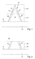
- data are initially provided by software technology (for example CAD data), which represent a structure 10 to be produced.
- CAD data software technology
- a pyramidal structure 10 is selected here, which is to be produced on a surface 12 of a substrate 14 by means of a three-dimensional prototyping method.
- the data representing the structure 10 are decomposed by software technology into a jacket wall 16 and into a volume section 18 of the structure 10 lying within the jacket wall 16.
- the volume portion 18 is bounded on the one hand by the jacket wall 16 to the outside, on the other hand by the surface 12 of the substrate 14 is completed.
- structures 10 which are bounded in all directions by a jacket wall 16 and / or are not arranged on a substrate are also conceivable.
- the structure 10 is further subdivided into partial regions 20, 20 ', which adjoin one another directly and in particular cover the structure 10 completely and, for example, without overlapping.
- partial regions 20, 20 ' which adjoin one another directly and in particular cover the structure 10 completely and, for example, without overlapping.
- partial walls 22, 22' of the jacket wall 16 are included, such that when the partial areas 20, 20 'are assembled, the partial walls 22, 22' complete the complete jacket wall 16 (in particular without overlapping).
- the substrate 14 is arranged, for example, in a bath of a lithography material 24, which thus fills the space above the surface 12 of the substrate 14 (see. FIG. 2 ).
- the lithography material 24 is, for example, a liquid or viscous plastic paint which is both photopolymerizable and thermopolymerizable.
- the lithography material 24 can be polymerized controlled by energy input methods and thereby solidified.
- a first spatially spatially resolving energy input method is used, in which spatially spatially resolved polymerization can be induced in a focal region of a writing beam.
- a second energy input method for example, the thermopolymerization can take place, as explained in more detail below.
- the jacket wall 16 in the lithography material 24 is first polymerized and solidified with the spatially spatially resolving first energy input method (eg photopolymerization in a spatially displaceable focus area of a writing beam).
- first energy input method eg photopolymerization in a spatially displaceable focus area of a writing beam
- subregions 20, 20 ' are written successively.
- the write area 26 for the first, resolving energy input method is first laid onto the first subarea 20 of the structure 10 and the subwalls 22 of the first subarea 20 are written.
- the writing area 26 is laid over the further subarea 20 'of the structure 10 and the subwalls 22' are written, ie polymerized and solidified.
- a volume 28 of still unpolymerized lithographic material is enclosed by the jacket wall 16 and, in the illustrated example, also by the surface 12 of the substrate 14. This is due to the fact that the selected first energy application method for generating the jacket wall 16 has a high spatial resolution and controls only the jacket wall 16 polymerized.
- the enclosed volume 28 corresponds to the volume portion 18 of the structure 10.
- the jacket wall 16 can be formed in an intermediate development step surrounding lithography material are removed, for example, in a bath of developer medium.
- the thus exposed structure of casing wall 16 and trapped, not yet polymerized volume 28 of lithographic material can then be spent a device for generating a second energy input method.
- the second energy input method no longer needs to have a high spatial resolution. Rather, it is conceivable that the second energy input method acts globally on the entire structure enclosed by the jacket wall 16. For example, the substrate 14 with the jacket wall 16 and the enclosed volume 28 can be brought into a furnace for heating. By the energy input with the second energy input method then the trapped volume 28 is also polymerized and solidified.
- the characteristic of the curing of the volume 28 can be influenced and so a volume portion 18 are generated in the interior of the jacket 16, for example, the physical properties of the volume portion 18 deviate from the jacket wall 16.
- the second energy input method is designed such that after curing of the volume 28, a homogeneous structure 10 is formed, which is composed of the shell wall 16 and the enclosed therein volume portion 18, wherein the shell wall 16 and volume portion 18 same structural properties and / or physical properties.
- FIG. 5 again the preparation of the data representing the desired structure 10 is illustrated.
- the structure 10 is in turn disassembled into a jacket wall 16 and an enclosed volume portion 18.
- a support structure 30 lying within the jacket wall 16 is defined, which has a plurality of support elements 32.
- the support elements 32 extend between sections of the jacket wall 16 and the surface 12 of the substrate 14.
- support elements may additionally or alternatively be provided which extend exclusively between sections of the jacket wall. This is particularly suitable when the volume portion is enclosed only by casing walls 16, and no limitation of the volume portion 18 by the surface 12 of the substrate 14 takes place.
- the structure 10 can in turn be divided into a plurality of partial areas 20, 20 ', which in turn each comprise partial walls 22, 22', which are composed to form the jacket wall 16. Subsections 34, 34 'of the support structure 30 are then also contained in the subregions 20, 20', so that the entire support structure 30 is formed by assembling the subregions 20, 20 '.
- the substrate 14 is introduced into a bath of lithography material 24 by way of example.
- the writing area 26 is placed over the first portion 20 of the structure 10 and with the spatially resolving first energy input method, the partial walls 22 of the jacket wall 16 and the sections 34 of the support structure 30 polymerized.
- the write area 26 is laid over the further subarea 20 'of the structure 10 and the remaining subwalls and subsections of the support structure are written. As a result, a volume 28 of unpolymerized lithography material 24 is enclosed within the jacket wall 16 and possibly the surface 12 of the substrate 14.
- the unpolymerized volume 28 is penetrated by the solidified support elements 32 of the support structure 30. Since the support elements 32 in the example shown extend between portions of the jacket wall 16 and the substrate surface 12, prevent the support members 32 collapse of the jacket wall 16, for example, in a subsequent intermediate development step. In alternative embodiments, support members 32 extending between portions of the shell wall 16 may avoid deforming or floating away areas of the shell wall 16.
- the enclosed volume 28 is in turn polymerized with a second energy input method, which does not have to have precise spatial resolution.
- material may be previously removed in an intermediate development step.
- the volume 28 may have other physical and / or mechanical properties after polymerization than the support structure 30.
- the mechanical properties of the structure 10 can be adjusted.
- the second energy input method is selected such that in Inside the jacket wall creates a completely homogeneous structure.
- the structure 10 is in turn decomposed into a jacket wall 16 and a volume portion 18 enclosed thereby.
- the decomposition takes place in a plurality of subregions 20a, 20b, 20c, 20d, 20e, 20f, 20g.
- These subregions 20a to 20g each contain in turn sub-walls 22a, 22b,..., Of which, for reasons of clarity, only a few are provided with separate reference symbols by way of example.
- the subregions 20a to 20g contain support structures with support elements extending between sections of the jacket wall 16 and / or with support elements extending between sections of the jacket wall 16 and a substrate surface 12 (not shown).
- the subareas 20a to 20g are in turn written sequentially one after the other and the sub-walls 22 contained therein and possibly support elements or sections of the support structure are written.
- the sequence of execution of the subregions may in particular be such that a deformation or change in position of sections already written during the writing of a subsequent subarea is prevented.
- the partial regions 20a, 20b, 20c, 20d, 20e, 20f, 20g are preferably written in the order reproduced.
- the jacket wall 16 in the various subregions 20a to 20g has wall sections with different wall thicknesses.
- partial walls can be made thicker in subregions which must receive a greater load from the structure 10 (for example, the partial walls 22d and 22c in the subregions 20d and 20c).
Abstract
Die Erfindung betrifft ein Verfahren zum Herstellen einer dreidimensionalen Struktur in einem mittels Energieeintragsmethoden polymerisierbaren und dadurch verfestigbaren Lithografiematerial, wobei zunächst mittels einer ersten, räumlich ortsauflösenden Energieeintragsmethode eine Mantelwandung der zu erzeugenden Struktur derart polymerisiert wird, dass ein Volumen an unpolymerisiertem Lithografiematerial eingeschlossen ist, wobei in einem Zwischenentwicklungsschritt die polymerisierte Mantelschale umgebendes Lithografiematerial entfernt wird, wobei danach mittels einer zweiten Energieeintragsmethode das durch die Mantelschale eingeschlossene Volumen polymerisiert wird.The invention relates to a method for producing a three-dimensional structure in a lithography material which can be polymerized by means of energy input methods and thereby solidified, wherein a jacket wall of the structure to be produced is first polymerized by means of a first, spatially spatially resolving energy input method in such a way that a volume of unpolymerized lithography material is enclosed an intermediate development step, the lithographic material surrounding the polymerized cladding shell is removed, after which the volume enclosed by the cladding shell is polymerized by means of a second energy input method.
Description
Die Erfindung betrifft ein Verfahren zum Herstellen einer dreidimensionalen Struktur in einem Lithografiematerial gemäß dem Anspruch 1.The invention relates to a method for producing a three-dimensional structure in a lithographic material according to
Solche lithografischen Verfahren finden z.B. bei der Herstellung von Prototypen oder bei der Erzeugung von Werkstücken mit speziellen Formanforderungen Verwendung. Insbesondere dienen derartige Verfahren auch der Erzeugung von Mikro- oder Nanostrukturen, z.B. zu experimentellen Zwecken sowie in Bereichen, in denen große Gestaltungsfreiheit erwünscht ist. Anwendungen bestehen z.B. in der Herstellung von abformbaren Topographien, Schablonen oder Matrizen für die Massenreplikation, in der Herstellung angepasster Stecker für Lichtleiter und in der Herstellung von angepassten Prothesen für medizinische Anwendungen.Such lithographic processes are used, for example, in the production of prototypes or in the production of workpieces with special shape requirements. In particular, such methods also serve to generate microstructures or nanostructures, for example for experimental purposes, as well as in areas in which great design freedom is desired. Applications include, for example, the production of moldable topographies, templates or matrices for mass replication, in the manufacture of adapted connectors for optical fibers and in the Production of adapted prostheses for medical applications.
Bekannt sind sogenannte Stereolithografie-Verfahren (z.B. aus der
Die genannten Verfahren erlauben zwar die Herstellung von Strukturen mit großer Gestaltungsfreiheit und hoher Präzision, können jedoch eine erhebliche Prozesszeit in Anspruch nehmen, insbesondere wenn großvolumige und zusammenhängende Strukturen erzeugt werden sollen. Dieses Problem tritt insbesondere auf, wenn die gewünschte Struktur sowohl großvolumige Abschnitte und außerdem Bereiche mit kleinen Strukturgrößen aufweist. Wenn dabei aufgrund der kleinen Strukturierung eine hohe Ortsauflösung erforderlich ist, so führt die Herstellung der großvolumigen Bereiche zu einer erheblich verlängerten Prozesszeit.Although the mentioned methods allow the production of structures with great design freedom and high precision, but can take a considerable process time, especially when large-volume and contiguous structures are to be produced. In particular, this problem occurs when the desired structure has both bulky sections and also areas of small feature sizes. If, due to the small structuring, a high spatial resolution is required, the production of the large-volume areas leads to a considerably longer process time.
Die Aufgabe der vorliegenden Erfindung besteht darin, die Herstellung von Strukturen mit einem hohen Grad an Gestaltungsfreiheit und einer möglichst kurzen Prozesszeit zu ermöglichen und dabei eine hohe Präzision und Formtreue der erzeugten Struktur zu gewährleisten.The object of the present invention is to enable the production of structures with a high degree of design freedom and the shortest possible process time while ensuring high precision and dimensional accuracy of the structure produced.
Diese Aufgabe wird durch ein Verfahren gemäß Anspruch 1 gelöst. Die gewünschte dreidimensionale Struktur wird in einem Lithografiematerial erzeugt, welches mittels Energieeintragsmethoden (z.B. Bestrahlung, Erwärmung) kontrolliert polymerisierbar und dadurch verfestigbar bzw. aushärtbar ist. Das Lithografiematerial liegt in seinem unpolymerisierten Zustand vorzugsweise flüssig, viskos, gelförmig oder fest vor. Beispielsweise kommt ein Lithografielack, insbesondere ein Negativlack, zum Einsatz. Gemäß dem Verfahren wird zunächst mittels einer ersten, räumlich ortsauflösenden Energieeintragsmethode eine Mantelwandung der zur erzeugenden Struktur derart definiert (d.h. in dem Lithografiematerial ortsaufgelöst polymerisiert), dass durch die Mantelwandung ein Volumen an unpolymerisiertem Lithografiematerial eingeschlossen ist. Daraufhin wird ein Zwischenentwicklungsschritt durchgeführt, in welchem das die polymerisierte Mantelwandung umgebende Lithografiematerial zumindest teilweise entfernt wird. Hierauf folgend wird mittels einer zweiten Energieeintragsmethode das mittels der Mantelwandung eingeschlossene Volumen an Lithografiematerial polymerisiert, d.h. verfestigt bzw. ausgehärtet.This object is achieved by a method according to
Insofern wird in dem unpolymerisierten Ausgangszustand des Lithografiematerials zunächst ein Volumen an Lithografiematerial gegenüber dem umgebenden Lithografiematerial durch die Mantelwandung abgegrenzt. Hierzu wird eine Energieeintragsmethode gewählt, mittels welcher die Mantelwandung mit der erforderlichen Ortsauflösung erzeugbar ist. Durch die Mantelwandung ist die gewünschte Struktur in dem umgebenden Lithografiematerial definiert. In dem Zwischenentwicklungsschritt wird das umgebende Lithografiematerial zumindest teilweise, vorzugsweise vollständig, entfernt.In this respect, in the unpolymerized starting state of the lithography material, first of all a volume of lithographic material is compared to the surrounding one Lithography material delimited by the jacket wall. For this purpose, an energy input method is selected, by means of which the jacket wall can be generated with the required spatial resolution. The jacket wall defines the desired structure in the surrounding lithographic material. In the intermediate development step, the surrounding lithographic material is at least partially, preferably completely, removed.
Insofern wird mit der hohen Ortsauflösung der ersten Methode nur die Mantelwandung geschrieben. Bei der Polymerisierung und Verfestigung des eingeschlossenen Lithografiematerials kann dann der Energieeintrag ohne eine hohe Ortsauflösung erfolgen. Dadurch kann erheblich Prozesszeit eingespart werden. Insbesondere ist es nicht erforderlich, großvolumige Abschnitte in zeitaufwändiger Weise mit der ortsauflösenden Energieeintragsmethode zu schreiben. Die Abmessungen der erzeugten Strukturmerkmale (Wandungen, Stützstrukturen usw.) können beispielsweise auf der Nanoskala (<10e-1 µm), Mikroskala (10e-1-10e+2 µm) und auf der Mesoskala (10e+2 - 10e+4 µm) liegen. Die erzeugten Volumina sind zwar grundsätzlich nicht beschränkt, können bei typischen Anwendungen aber im Bereich < 1 Kubikzentimeter liegen.In this respect, with the high spatial resolution of the first method, only the cladding wall is written. In the polymerization and solidification of the enclosed lithographic material then the energy input can be done without a high spatial resolution. This can save considerable process time. In particular, it is not necessary to write large-volume sections in a time-consuming manner with the spatially resolving energy input method. The dimensions of the generated structural features (walls, supporting structures, etc.) can be measured, for example, on the nanoscale (<10e-1 μm), micro scale (10e-1-10e + 2 μm) and on the mesoscale (10e + 2 - 10e + 4 μm) lie. Although the volumes produced are basically not limited, they can be in the range of <1 cubic centimeter in typical applications.
Bei dem erfindungsgemäßen Verfahren wird trotz der deutlich verkürzten Prozesszeit eine hohe Ortsauflösung gewährleistet, da die einhüllende Mantelwandung mit der ortsauflösenden ersten Energieeintragsmethode erzeugt wird. Dadurch wird ein Rapid Prototyping mit kürzeren Prozesszeiten möglich.In the method according to the invention, a high spatial resolution is ensured despite the significantly reduced process time, since the enveloping jacket wall is generated with the spatially resolving first energy input method. This enables rapid prototyping with shorter process times.
Grundsätzlich ist es denkbar, dass das eingeschlossene Volumen nach dem zweiten Energieeintragsprozess einen anderen Polymerisierungsgrad und/oder andere mechanische Eigenschaften und/oder andere optische Eigenschaften aufweist, als die umgebende Mantelwandung. Hierdurch können Strukturen mit verschiedenen mechanischen oder optischen Eigenschaften erzeugt werden. Außerdem ist eine außenliegende Stützstruktur nicht zwingend erforderlich. Solche außenliegenden Stützstrukturen haben bei den eingangs erläuterten Verfahren zum schichtweisen Aufbauen von Strukturen in dem Lithografiematerial u.a. die Funktion, die lageweise entstehende Struktur in dem Bad aus Lithografiematerial zu fixieren und ein Wegschwimmen von Abschnitten der unfertigen Struktur zu verhindern, was bei Aufbau einer Mantelschale unterbunden wird.In principle, it is conceivable that the enclosed volume after the second energy input process has a different degree of polymerization and / or different mechanical properties and / or different optical properties than the surrounding jacket wall. As a result, structures with different mechanical or optical properties can be generated. In addition, an external support structure is not mandatory. Such external support structures have u.a. in the method explained above for the layered structure of structures in the lithographic material. the function to fix the layered structure in the bath of lithographic material and to prevent floating away of sections of the unfinished structure, which is prevented in the construction of a shell shell.
Vorzugsweise ist die zweite Energieeintragsmethode verschieden von der ersten Energieeintragsmethode. Insbesondere kann die zweite Energieeintragsmethode als nicht ortsauflösende Methode ausgestaltet sein und/oder auf das gesamte von der Mantelwandung eingeschlossene unpolymerisierte Lithografiematerial wirken. Insofern kann die erste Energieeintragsmethode eine Ortsauflösung aufweisen, welche um ein Vielfaches höher ist, als die Ortsauflösung der zweiten Energieeintragsmethode. Beispielsweise kann die zweite Energieeintragsmethode ein Erwärmungsverfahren, ein Baking-Verfahren oder ein anderes Curing-Verfahren sein. Beispielsweise kann die Struktur mit der polymerisierten Mantelwandung in einen Ofen, z.B. Konvektionsofen oder Röhrenofen, gebracht werden oder Kontakt mit einer Heizeinrichtung (z.B. Heizplatte) hergestellt werden. Denkbar ist auch eine Energieeintragsmethode unter Ausnutzung von Mikrowellenbestrahlung, Infrarotbestrahlung, UV-Bestrahlung.Preferably, the second energy input method is different from the first energy input method. In particular, the second energy input method can be configured as a non-spatially resolving method and / or act on the entire unpolymerized lithography material enclosed by the jacket wall. In this respect, the first energy input method can have a spatial resolution that is many times higher than the spatial resolution of the second energy input method. For example, the second energy input method may be a heating method, a baking method or another curing method. For example, the structure with the polymerized jacket wall can be brought into an oven, eg convection oven or tube oven, or made contact with a heater (eg hot plate). Also conceivable is an energy input method utilizing Microwave irradiation, infrared irradiation, UV irradiation.
Demgegenüber erfolgt bei der ersten, ortsauflösenden Energieeintragsmethode die Polymerisation des Lithografiematerials vorzugsweise in einem räumlich eng begrenzten und insbesondere verlagerbaren Fokusbereichs eines Schreibstrahls einer Strahlungsquelle. Denkbar ist auch eine Parallelisierung des Verfahrens, wobei ein oder mehrere Fokusbereiche mehrerer Schreibstrahle mehrerer Strahlungsquellen verwendet werden, die ein ortsaufgelöstes Belichtungsmuster bilden können. Die erste Energieeintragsmethode kann z.B. eine Laserlithografiemethode oder Elektronenstrahllithografiemethode sein, insbesondere eine 3D-Laserlithografiemethode. Die Definition der Struktur mit einem Schreibstrahl ist zwar zeitaufwändig, jedoch lassen sich hochpräzise Strukturen erzielen. Da nur die Mantelwandung definiert wird, kann jedoch trotzdem eine kurze Strukturierungszeit erzielt werden.In contrast, in the first, spatially resolving energy input method, the polymerization of the lithography material preferably takes place in a spatially narrowly limited and in particular displaceable focus region of a writing beam of a radiation source. Also conceivable is a parallelization of the method, wherein one or more focus areas of multiple write beams of multiple radiation sources are used, which can form a spatially resolved exposure pattern. The first energy input method may e.g. a laser lithography method or electron beam lithography method, in particular a 3D laser lithography method. Although the definition of the structure with a writing beam is time-consuming, highly precise structures can be achieved. Since only the jacket wall is defined, however, a short structuring time can nevertheless be achieved.
Bei der ersten Energieeintragsmethode erfolgt die Polymerisation des Lithografiematerials vorzugsweise durch Zwei-Photonen-Absorption oder Multi-Photonen-Absorption in dem Fokusbereich des Schreibstrahls. Das Lithografiematerial ist insbesondere derart ausgebildet und die Strahlungsquelle insbesondere derart auf das Lithografiematerial abgestimmt, dass eine Polymerisation nur mittels Zwei-Photonen-Absorption oder Multi-Photonen-Absorption möglich ist. Hierzu kann beispielsweise die Wellenlänge des Schreibstrahls so groß gewählt sein (und damit die Photonenenergie so niedrig sein), dass der für die Polymerisation erforderliche Energieeintrag nur durch gleichzeitige Absorption zweier oder mehrerer Photonen erreicht wird. Die Wahrscheinlichkeit für einen solchen Absorptionsprozess ist intensitätsabhängig und im Vergleich zum übrigen Schreibstrahl in dem Fokusbereich deutlich erhöht. Im Rahmen von grundsätzlichen Überlegungen ergibt sich, dass die Wahrscheinlichkeit zur Absorption von zwei oder mehreren Photonen vom Quadrat oder einer höheren Potenz der Strahlungsintensität abhängen kann. Im Gegensatz hierzu weist die Wahrscheinlichkeit für die Absorption eines Photons eine andere Intensitätsabhängigkeit auf. Beim Eindringen des Schreibstrahls in das Lithografiematerial erfolgt außerdem grundsätzlich eine Dämpfung. So kann beispielsweise das Beer'sche Gesetz für die Intensitätsabnahme in Abhängigkeit der Eindringtiefe in das Lithografiematerial gelten. Dies führt dazu, dass eine ortsauflösende Polymerisation in einem Fokusbereich tief unter der Oberfläche des Lithografiematerials unter Ausnutzung einer Ein-Photonen-Absorption problematisch wäre, da aufgrund der Dämpfung bei Fokussierung unterhalb der Oberfläche im Fokusbereich nicht zwingend die höchste Intensität vorliegt. Bei den eingangs beschriebenen Stereolithografiemethoden erfolgt daher der Aufbau der Struktur schichtweise stets nur durch Belichtung des Lithografiematerials an der Oberfläche eines Bades aus Lithografiematerial. Bei Ausnutzung der Zwei-Photonen-Absorption oder der Multi-Photonen-Absorption ist dieses lageweise Absenken der Struktur in ein Bad aus Lithografiematerial nicht zwingend nötig, da die Polymerisation auch bei größerer Eindringtiefe aufgrund der anderen Gesetzmäßigkeiten auf den Fokusbereich des Schreibstrahls beschränkt sein kann.In the first energy input method, the polymerization of the lithography material is preferably carried out by two-photon absorption or multi-photon absorption in the focus area of the write beam. In particular, the lithography material is designed in this way and the radiation source is matched in particular to the lithography material such that polymerization is possible only by means of two-photon absorption or multi-photon absorption. For this purpose, for example, the wavelength of the write beam can be chosen to be so large (and thus the photon energy can be so low) that the energy input required for the polymerization can only be achieved by simultaneous absorption of two or more photons is reached. The probability of such an absorption process is intensity-dependent and significantly increased compared to the rest of the writing beam in the focus area. Fundamental considerations suggest that the probability of absorbing two or more photons may depend on the square or higher power of the radiation intensity. In contrast, the probability of photon absorption has a different intensity dependence. When penetration of the writing beam in the lithographic material also takes place in principle a damping. For example, Beer's Law may apply to the intensity decrease as a function of the depth of penetration into the lithographic material. As a result, a spatially resolving polymerization in a focal region deep below the surface of the lithographic material using single-photon absorption would be problematic, since the highest intensity is not necessarily present in the focal region due to the attenuation when focusing below the surface. In the stereolithography methods described above, therefore, the structure of the structure always takes place in layers only by exposure of the lithography material to the surface of a bath of lithographic material. When utilizing the two-photon absorption or the multi-photon absorption of this layerwise lowering of the structure in a bath of lithographic material is not absolutely necessary, since the polymerization may be limited even at greater penetration depth due to the other laws on the focus area of the writing beam.
Nach einer bevorzugten Ausgestaltung wird mittels der ersten, ortsauflösenden Energieeintragsmethode und vorzugsweise gemeinsam mit der Mantelwandung eine innerhalb der Mantelwandung liegende Stützstruktur definiert, d.h. auspolymerisiert. Die Stützstruktur liegt insofern insbesondere innerhalb des durch die Mantelwandung eingeschlossenen Volumens und kann dieses ggf. auch in Teilvolumina unterteilen. Bei der Definition Stützstruktur kann auch ein geringfügiger Überlapp mit der Mantelwandung vorteilhaft sein, so dass Elemente der Stützstruktur geringfügig mit der Mantelwandung überlappen und so mit dieser fest verbunden sind. Die Stützstruktur weist insbesondere Stützelemente auf, welche sich zwischen Abschnitten der Mantelwandung und/oder zwischen Abschnitten der Mantelwandung und einem Substrat erstrecken. Durch die Stützstruktur kann die Formtreue der durch die Mantelwandung vorgegebenen Form gewahrt werden. Insbesondere kann verhindert werden, dass die durch die Mantelwandung definierte Struktur bei dem Zwischenentwicklungsschritt, während der zweiten Energieeintragsmethode oder einem Curing-Schritt verformt wird oder kollabiert. Insgesamt kann sichergestellt werden, dass nach Aushärtung des eingeschlossenen Volumens die erzielte Form mit der durch die Mantelwandung vorgegebenen Form übereinstimmt.According to a preferred embodiment, by means of the first, spatially resolving energy input method and preferably together with the jacket wall, an inside the shell wall lying support structure defined, ie polymerized. The support structure is so far in particular within the volume enclosed by the jacket wall and may possibly also subdivide this into subvolumes. In the definition support structure, a slight overlap with the jacket wall may be advantageous, so that elements of the support structure slightly overlap with the jacket wall and are thus firmly connected to this. The support structure in particular has support elements which extend between sections of the jacket wall and / or between sections of the jacket wall and a substrate. Due to the support structure, the dimensional accuracy of the predetermined by the shell wall form can be maintained. In particular, it can be prevented that the structure defined by the cladding wall is deformed or collapsed at the intermediate development step, during the second energy input method, or at a curing step. Overall, it can be ensured that after hardening of the enclosed volume, the shape achieved matches the shape predetermined by the jacket wall.
Anders als bei bekannten Strukturierungsverfahren mit außenliegenden Stützstrukturen muss eine innen liegende Stützstruktur nach Fertigstellung der gewünschten Struktur nicht entfernt werden. So kann Prozesszeit zur Nachbearbeitung (Finishing) der Struktur nach Aushärten des inneren Volumens eingespart werden. Darüber hinaus bildet eine außenliegende Stützstruktur nach ihrer Entfernung in der Regel ein Abfallprodukt, was bei Verwendung von teuren Lithografiematerialien zu unerwünschten Kostenerhöhungen führen kann und durch die innen liegende Stützstruktur vermieden wird.Unlike known structuring methods with external support structures, an internal support structure does not have to be removed after completion of the desired structure. In this way, process time for finishing the structure after curing of the internal volume can be saved. In addition, an external support structure generally forms a waste product after its removal, which can lead to undesirable cost increases when using expensive lithographic materials and is avoided by the internal support structure.
Die Gestaltung der Stützstruktur erlaubt es außerdem, die mechanischen Eigenschaften der gewünschten Struktur einzustellen und zu beeinflussen. So kann beispielsweise durch geeignete Stützstrukturen ein federnder Kern in der Mantelwandung erzeugt werden. Denkbar ist, die Elastizität der gewünschten Struktur zu beeinflussen. Die Stützstruktur kann beispielsweise fachwerkartig, in der Art eines 3D-Wabengitters, als kubisches Gitter und/oder als Anordnung aus sich zwischen Abschnitten der Mantelwandung erstreckenden Streben oder Wandungen ausgestaltet sein.The design of the support structure also makes it possible to adjust and influence the mechanical properties of the desired structure. Thus, for example, by suitable support structures, a resilient core can be generated in the shell wall. It is conceivable to influence the elasticity of the desired structure. The support structure may be designed, for example, like a truss, in the manner of a 3D honeycomb grid, as a cubic grid and / or as an arrangement of struts or walls extending between sections of the casing wall.
Vorzugsweise ist die Mantelwandung eine ein Volumen vollständig umschließende Mantelwandung. Denkbar ist jedoch auch, dass das Lithografiematerial auf einem Substrat aufgebracht ist und ein Abschnitt einer Oberfläche des Substrates zusammen mit der Mantelwandung das Volumen an unpolymerisiertem Lithografiematerial einschließt. Das Substrat kann grundsätzlich beliebig sein, z.B. ein Glas- oder Halbleiterwafer, ein Keramikteil oder ein Formkörper. Die Oberfläche des Substrates dient insofern als Teil der Begrenzung des eingeschlossenen Volumens. Dadurch muss die Mantelwandung das Volumen nicht vollständig einschließen und muss in dem ersten Energieeintragsschritt nicht erzeugt werden. Dies bringt eine weitere Zeitersparnis mit sich, da ein Abschluss des eingeschlossenen Volumens teilweise von dem Substrat gebildet ist.Preferably, the jacket wall is a jacket wall completely enclosing a volume. However, it is also conceivable that the lithography material is applied to a substrate and a portion of a surface of the substrate together with the jacket wall encloses the volume of unpolymerized lithography material. The substrate may in principle be arbitrary, e.g. a glass or semiconductor wafer, a ceramic part or a shaped body. The surface of the substrate serves as part of the confinement of the enclosed volume. As a result, the jacket wall does not have to completely enclose the volume and does not have to be produced in the first energy input step. This brings a further saving of time since a closed volume closure is partially formed by the substrate.
Der Zwischenentwicklungsschritt ist vorzugsweise derart ausgestaltet, dass das durch die Mantelwandung eingeschlossene Volumen an unpolymerisiertem Lithografiematerial weitgehend unbeeinflusst bleibt, insbesondere ungehärtet und/oder unangelöst bleibt. Der Zwischenentwicklungsschritt kann beispielsweise ein nasschemischer Entwicklungsschritt sein und insbesondere dazu ausgestaltet sein, ein Ablösen des die Mantelschale umgebenden Lithografiematerials zu bewirken. Denkbar ist beispielsweise ein Bad in einem Entwicklermedium.The intermediate development step is preferably designed in such a way that the volume of unpolymerized lithographic material enclosed by the jacket wall remains largely unaffected, in particular remains uncured and / or unfixed. The intermediate development step may include, for example be wet-chemical development step and in particular be designed to cause a detachment of the surrounding the jacket shell lithographic material. For example, a bath in a developer medium is conceivable.
Vorzugsweise wird ein Lithografiematerial verwendet, welches photopolymerisierbar und thermopolymerisierbar ist. Insofern wird unter einem photopolymerisierbaren Material beispielsweise ein lichtaushärtender Kunststoff verstanden, welcher mit der ersten Energieeintragsmethode z.B. mittels eines Schreibstrahls aus Licht, Laserlicht, UV oder Ähnlichem polymerisierbar ist. Ein thermopolymerisierbares Lithografiematerial ist beispielsweise ein Material, welches bei Erwärmung über einer Schwelltemperatur eine Umwandlung in den polymerisierten Zustand vollzieht. Die zweite Energieeintragsmethode ist dann vorzugsweise ein Erwärmen. Denkbar ist jedoch auch die Verwendung eines nur photopolymerisierbaren Materials, wobei die erste Energieeintragsmethode ein ortsaufgelöstes Bestrahlen ist und die zweite Energieeintragsmethode eine großvolumige Bestrahlung umfasst, beispielsweise ein UV-Curing.Preferably, a lithography material is used which is photopolymerizable and thermopolymerizable. In this respect, a photopolymerizable material is understood, for example, to be a light-curing plastic which, with the first energy input method, comprises e.g. by means of a writing beam of light, laser light, UV or the like is polymerizable. For example, a thermopolymerizable lithographic material is a material that undergoes conversion to the polymerized state when heated above a threshold temperature. The second energy input method is then preferably a heating. However, it is also conceivable to use a photopolymerizable material, wherein the first energy input method is a spatially resolved irradiation and the second energy input method comprises a large-volume irradiation, for example a UV curing.
Die Materialwandung kann mit Wandungsabschnitten ausgestaltet sein, die jeweils verschiedene Wandungsdicken aufweisen. Dadurch können mechanische Eigenschaften der Materialwandung eingestellt werden. Denkbar ist außerdem, dass nur solche Wandungsabschnitte mit einer großen Wanddicke ausgestaltet werden, welche aufgrund der Strukturform eine hohe Stabilität aufweisen müssen, beispielsweise um ein Kollabieren der Mantelwandung bei dem Zwischenentwicklungsschritt zu vermeiden.The material wall can be configured with wall sections which each have different wall thicknesses. As a result, mechanical properties of the material wall can be adjusted. It is also conceivable that only those wall sections are designed with a large wall thickness, which must have a high stability due to the structural shape, for example, to avoid collapse of the jacket wall in the intermediate development step.
Zur weiteren Ausgestaltung des Verfahrens ist denkbar, dass nach dem Zwischenentwicklungsschritt ein Nachhärten der Mantelwandung erfolgt und/oder nach der Polymerisation mit der zweiten Energieeintragsmethode ein Nachhärten der erzielten Struktur erfolgt. Das Nachhärten kann beispielsweise ein Curing-Schritt und/oder eine chemische Behandlung in einem Härter-Bad umfassen.For a further embodiment of the method, it is conceivable that after the intermediate development step, a post-curing of the Mantelwandung takes place and / or after the polymerization with the second energy input method, a post-curing of the structure achieved. The post cure may include, for example, a curing step and / or a chemical treatment in a curing bath.
Grundsätzlich kann ein vorgeschalteter softwaretechnischer Datenverarbeitungs-Prozess vorgesehen sein, bei dem zunächst die zu erzeugende Struktur repräsentierende Daten bereitgestellt werden (z.B. CAD-Daten), und dann ein wenigstens einer Mantelschale zugeordneter Datensatz softwaretechnisch ermittelt wird, so dass die Mantelschale und das eingeschlossene Volumen zusammen die gewünschte Struktur ergeben. Eine Einrichtung zur Durchführung der ersten Energieeintragsmethode (z.B. ein 3D-Laser-Lithograf) kann dann mit dem Datensatz entsprechend angesteuert werden.In principle, an upstream software-technical data processing process can be provided, in which first the data representing the structure to be generated are provided (eg CAD data), and then a data record associated with at least one jacket shell is determined by software, so that the jacket shell and the enclosed volume together give the desired structure. A means for performing the first energy input method (e.g., a 3D laser lithograph) may then be appropriately driven with the data set.
Bei Strukturen mit großvolumigen Abschnitten kann die Mantelwandung auch sequentiell aus Teilwandungen zusammengesetzt werden. Hierzu wird die Mantelwandung dadurch definiert, dass sequentiell eine Mehrzahl von Teilwandungen erzeugt werden, wobei zum Schreiben der Teilwandungen ein Schreibbereich einer Einrichtung zur Durchführung der ortsauflösenden Energieeintragsmethode sequentiell verlagert und positioniert wird, und wobei jeweils in dem Schreibbereich eine Teilwandung definiert wird, d.h. auspolymerisiert wird.In structures with large-volume sections, the jacket wall can also be assembled sequentially from partial walls. For this purpose, the jacket wall is defined by sequentially forming a plurality of partial walls, wherein for writing the partial walls, a writing area of a device for performing the spatially resolving energy input method is sequentially displaced and positioned, and a partial wall is defined in the writing area, i. is polymerized.
Hierzu kann zunächst in einem Datenverarbeitungsschritt die die Struktur repräsentierenden Daten softwaretechnisch in die den Teilwandungen zugeordneten Teilbereiche zerlegt werden, beispielsweise in einem sogenannten Splitting-Verfahren. Die Einrichtung zur Durchführung der ortsauflösenden Energieeintragsmethode (z.B. 3D-Laser-Lithograf) kann dann entsprechend angesteuert werden.For this purpose, in a data processing step, the data representing the structure can first be decomposed by software technology into the subregions assigned to the partial walls, for example in a so-called splitting method. The device for carrying out the spatially resolving energy input method (eg 3D laser lithograph) can then be controlled accordingly.
Grundsätzlich ist der Schreibbereich durch die technischen Gegebenheiten der Energieeintragseinrichtung oder Belichtungseinrichtung vorgegeben und umfasst insbesondere denjenigen Bereich, in welchen der Schreibstrahl mit der erforderlichen Ortsauflösung gelenkt werden kann. Die Erzeugung der Mantelwandung aus zusammengesetzten Teilwandungen ist insbesondere dann vorteilhaft, wenn die ortsauflösende Energieeintragsmethode mittels einer Einrichtung vorgenommen wird, welche einen im Vergleich zur Größe der zu erzeugenden Struktur kleinen Schreibbereich aufweist.In principle, the write area is predetermined by the technical conditions of the energy input device or exposure device and, in particular, includes that area in which the write beam can be steered with the required spatial resolution. The production of the jacket wall from composite partial walls is particularly advantageous if the spatially resolving energy input method is carried out by means of a device which has a small writing area compared to the size of the structure to be produced.
Die Erfindung wird im Folgenden anhand der Figuren näher erläutert.The invention will be explained in more detail below with reference to FIGS.
Es zeigen:
-
Figur 1 -
Figuren 2 bis 4 Skizzierte Darstellungen zur Veranschaulichung der Herstellungsschritte für dieStruktur gemäß Figur 1 ; -
Figur 5 Skizzierte Darstellung zur Erläuterung des Herstellungsverfahrens für eine Struktur mit anderen Gestaltungsmerkmalen; -
Figur 6 Skizzierte Darstellung zur Erläuterung eines Zwischenschritts der Herstellung der Struktur gemäßFigur 5 ; -
Figur 7 Skizzierte Darstellung zur Erläuterung des Herstellungsverfahrens für eine komplexere Struktur.
-
FIG. 1 Sketched representation of a structure to be produced to explain the manufacturing process; -
FIGS. 2 to 4 Sketched representations to illustrate the manufacturing steps for the structure according toFIG. 1 ; -
FIG. 5 Sketched representation to explain the manufacturing process for a structure with other design features; -
FIG. 6 Sketched representation for explaining an intermediate step of the production of the structure according toFIG. 5 ; -
FIG. 7 Outlined illustration to explain the manufacturing process for a more complex structure.
In der nachfolgenden Beschreibung sowie in den Figuren sind für identische oder einander entsprechende Merkmale jeweils dieselben Bezugszeichen verwendet.In the following description as well as in the figures, the same reference numerals are used for identical or corresponding features.
Anhand der
Hierzu werden zunächst softwaretechnisch Daten bereitgestellt (z.B. CAD-Daten), welche eine herzustellende Struktur 10 repräsentieren. Beispielhaft ist hier eine pyramidale Struktur 10 gewählt, die auf einer Oberfläche 12 eines Substrates 14 im Wege eines dreidimensionalen Prototyping-Verfahrens hergestellt werden soll. Hierzu werden die die Struktur 10 repräsentierenden Daten softwaretechnisch in eine Mantelwandung 16 und in einen innerhalb der Mantelwandung 16 liegenden Volumenabschnitt 18 der Struktur 10 zerlegt. Im dargestellten Beispiel wird der Volumenabschnitt 18 einerseits von der Mantelwandung 16 nach außen hin begrenzt, andererseits durch die Oberfläche 12 des Substrats 14 abgeschlossen. Denkbar sind jedoch auch Strukturen 10, die in sämtliche Richtungen durch eine Mantelwandung 16 begrenzt sind und/oder nicht auf einem Substrat angeordnet sind.For this purpose, data are initially provided by software technology (for example CAD data), which represent a
Softwaretechnisch erfolgt ferner eine Zerlegung der Struktur 10 in Teilbereiche 20, 20', welche unmittelbar aneinander angrenzen und die Struktur 10 insbesondere vollständig und z.B. überlappungsfrei überdecken. Je nach Anwendung und/oder Präzision der verwendeten Instrumente kann jedoch auch ein geringfügiger Überlapp vorteilhaft sein. In jedem Teilbereich 20, 20' sind Teilwandungen 22, 22' der Mantelwandung 16 umfasst, derart, dass sich bei Zusammensetzen der Teilbereiche 20, 20' die Teilwandungen 22, 22' zu der vollständigen Mantelwandung 16 (insbesondere überlappungsfrei) ergänzen.In terms of software, the
Anhand der
Zur Herstellung der Struktur 10 wird zunächst mit der räumlich ortsauflösenden ersten Energieeintragsmethode (z.B. Photopolymerisation in einem räumlich verlagerbaren Fokusbereich eines Schreibstrahls) nur die Mantelwandung 16 in dem Lithografiematerial 24 polymerisiert, verfestigt.To produce the
Da bei Einrichtungen zur Erzeugung eines räumlich ortsaufgelösten Energieeintrags oftmals der Schreibbereich aufgrund der Präzisionsanforderungen beschränkt ist, werden die Strukturdetails in den Teilbereichen 20, 20' nacheinander geschrieben. Insbesondere sind die Teilbereiche 20, 20' derart gewählt, dass sie jeweils innerhalb eines Schreibbereiches 26 der Einrichtung für den ersten, ortsauflösenden Energieeintrag (z.B. Laser-Lithograf) liegen.Since in devices for generating spatially spatially resolved energy input often the writing area is limited due to the precision requirements, the structural details in the
Wie in
Um das eingeschlossene Volumen 28 ebenfalls zu verfestigen und so die Struktur 10 dauerhaft zu erzeugen, kann in einem Zwischenentwicklungsschritt das die Mantelwandung 16 umgebende Lithografiematerial entfernt werden, beispielsweise in einem Bad aus Entwicklermedium.In order to likewise solidify the
Die so freigelegte Struktur aus Mantelwandung 16 und eingeschlossenem, noch nicht polymerisierten Volumen 28 an Lithografiematerial kann dann eine Einrichtung zur Erzeugung einer zweiten Energieeintragsmethode verbracht werden. Die zweite Energieeintragsmethode muss keine hohe Ortsauflösung mehr aufweisen. Vielmehr ist denkbar, dass die zweite Energieeintragsmethode global auf die gesamte, von der Mantelwandung 16 eingeschlossene Struktur wirkt. Beispielsweise kann das Substrat 14 mit der Mantelwandung 16 und dem eingeschlossenen Volumen 28 in einen Ofen zur Erwärmung gebracht werden. Durch den Energieeintrag mit der zweiten Energieeintragsmethode wird dann das eingeschlossene Volumen 28 ebenfalls polymerisiert und verfestigt.The thus exposed structure of
Wie in
Anhand der
Um einer beschränkten Größe eines Schreibbereiches für die erste Energieeintragsmethode gerecht zu werden, kann die Struktur 10 wiederum in mehrere Teilbereiche 20, 20' zerlegt werden, welche wiederum jeweils Teilwandungen 22, 22' umfassen, die sich zu der Mantelwandung 16 zusammensetzen. In den Teilbereichen 20, 20' sind dann auch Teilabschnitte 34, 34' der Stützstruktur 30 enthalten, so dass durch Zusammensetzen der Teilbereiche 20, 20' die gesamte Stützstruktur 30 entsteht.In order to cope with a limited size of a write area for the first energy input method, the
Anhand von
In darauffolgenden Verfahrensschritten wird wiederum mit einer zweiten Energieeintragsmethode, welche keine präzise Ortsauflösung aufweisen muss, das eingeschlossene Volumen 28 polymerisiert. Je nach Bedarf kann vorher Material in einem Zwischenentwicklungsschritt entfernt werden. Durch Einstellung der Parameter für die zweite Energieeintragsmethode kann beispielsweise das Volumen 28 auch nach Polymerisation andere physikalische und/oder mechanische Eigenschaften aufweisen, als die Stützstruktur 30. So können die mechanischen Eigenschaften der Struktur 10 eingestellt werden. Denkbar ist jedoch auch, dass die zweite Energieeintragsmethode derart gewählt ist, dass im Innern der Mantelwandung eine vollständig homogene Struktur entsteht.In subsequent process steps, the
Anhand von
Zur Herstellung der Struktur 10 werden wiederum die Teilbereiche 20a bis 20g sequentiell nacheinander geschrieben und die hierin enthaltenen Teilwandungen 22 und ggf. Stützelemente oder Abschnitte der Stützstruktur geschrieben. Hierbei kann die Reihenfolge der Abarbeitung der Teilbereiche insbesondere derart erfolgen, dass eine Verformung oder Lageveränderung von bereits geschriebenen Abschnitten während des Schreibens eines folgenden Teilbereiches verhindert wird. Im dargestellten Beispiel werden vorzugsweise die Teilbereiche 20a, 20b, 20c, 20d, 20e, 20f, 20g in der wiedergegebenen Reihenfolge geschrieben. Dadurch kann beispielsweise verhindert werden, dass ein vorher geschriebener Teilbereich 20g mit der darin verfestigten Teilwandung 22g noch nicht durch andere Teilwandungen abgestützt ist und in dem Bad aus Lithografiematerial absinkt. Denkbar ist außerdem, dass die Mantelwandung 16 in den verschiedenen Teilbereichen 20a bis 20g Wandungsabschnitte mit unterschiedlichen Wandungsdicken aufweist. Beispielsweise können Teilwandungen in Teilbereichen dicker ausgeführt werden, welche eine größere Traglast von der Struktur 10 aufnehmen müssen (beispielsweise die Teilwandungen 22d und 22c in den Teilbereichen 20d und 20c).In order to produce the
Claims (10)
Applications Claiming Priority (1)
| Application Number | Priority Date | Filing Date | Title |
|---|---|---|---|
| DE102014221480.7A DE102014221480B4 (en) | 2014-10-22 | 2014-10-22 | Method for producing a three-dimensional structure |
Publications (3)
| Publication Number | Publication Date |
|---|---|
| EP3012688A1 true EP3012688A1 (en) | 2016-04-27 |
| EP3012688B1 EP3012688B1 (en) | 2019-10-02 |
| EP3012688B2 EP3012688B2 (en) | 2023-02-08 |
Family
ID=53835320
Family Applications (1)
| Application Number | Title | Priority Date | Filing Date |
|---|---|---|---|
| EP15180364.0A Active EP3012688B2 (en) | 2014-10-22 | 2015-08-10 | Method for producing a three-dimensional structure |
Country Status (5)
| Country | Link |
|---|---|
| US (1) | US9937664B2 (en) |
| EP (1) | EP3012688B2 (en) |
| JP (1) | JP6560953B2 (en) |
| CN (1) | CN105549328B (en) |
| DE (1) | DE102014221480B4 (en) |
Cited By (2)
| Publication number | Priority date | Publication date | Assignee | Title |
|---|---|---|---|---|
| EP3702132B1 (en) | 2019-02-26 | 2023-01-11 | UpNano GmbH | Method for lithography-based generative production of a three-dimensional component |
| WO2023094133A1 (en) * | 2021-11-25 | 2023-06-01 | Bayerische Motoren Werke Aktiengesellschaft | Method for additive manufacturing of a three-dimensional object |
Families Citing this family (8)
| Publication number | Priority date | Publication date | Assignee | Title |
|---|---|---|---|---|
| EP3317064B1 (en) | 2015-06-30 | 2022-09-28 | The Gillette Company LLC | Method of manufacturing polymeric cutting edge structures |
| DE102015121748A1 (en) * | 2015-12-14 | 2017-06-14 | Cl Schutzrechtsverwaltungs Gmbh | Device for the generative production of a three-dimensional object |
| US10562200B2 (en) * | 2016-06-28 | 2020-02-18 | The Gillette Company Llc | Polymeric cutting edge structures and method of manufacturing polymeric cutting edge structures |
| US10780599B2 (en) | 2016-06-28 | 2020-09-22 | The Gillette Company Llc | Polymeric cutting edge structures and method of manufacturing polymeric cutting edge structures |
| DE102016014229A1 (en) | 2016-11-30 | 2018-05-30 | Giesecke+Devrient Currency Technology Gmbh | Production method for printing plates for intaglio printing and printing plate for intaglio printing |
| US10413167B2 (en) | 2017-05-30 | 2019-09-17 | Synaptive Medical (Barbados) Inc. | Micro-optical surgical probes and micro-optical probe tips and methods of manufacture therefor |
| EP3986710A1 (en) * | 2019-06-24 | 2022-04-27 | Essilor International | Method and machine for the production of an optical element by additive manufacturing |
| US11661468B2 (en) * | 2020-08-27 | 2023-05-30 | Align Technology, Inc. | Additive manufacturing using variable temperature-controlled resins |
Citations (2)
| Publication number | Priority date | Publication date | Assignee | Title |
|---|---|---|---|---|
| US4575330A (en) | 1984-08-08 | 1986-03-11 | Uvp, Inc. | Apparatus for production of three-dimensional objects by stereolithography |
| DE19507881B4 (en) | 1994-03-10 | 2006-11-23 | Materialise N.V. | Method of supporting an object made by stereolithography or another rapid prototype manufacturing method |
Family Cites Families (5)
| Publication number | Priority date | Publication date | Assignee | Title |
|---|---|---|---|---|
| US5198159A (en) | 1990-10-09 | 1993-03-30 | Matsushita Electric Works, Ltd. | Process of fabricating three-dimensional objects from a light curable resin liquid |
| JP2795126B2 (en) * | 1993-04-16 | 1998-09-10 | 株式会社デンソー | Curved surface processing method and device |
| US6364986B1 (en) * | 1999-10-04 | 2002-04-02 | The United States Of America As Represented By The Secretary Of The Navy | High-strength parts formed using stereolithography |
| US6730256B1 (en) * | 2000-08-04 | 2004-05-04 | Massachusetts Institute Of Technology | Stereolithographic patterning with interlayer surface modifications |
| WO2005005121A2 (en) * | 2003-07-11 | 2005-01-20 | Koninklijke Philips Electronics N.V. | A method of manufacturing a mould for producing an optical surface, a method of producing a contact lens and a device for use with these methods |
-
2014
- 2014-10-22 DE DE102014221480.7A patent/DE102014221480B4/en not_active Revoked
-
2015
- 2015-08-10 EP EP15180364.0A patent/EP3012688B2/en active Active
- 2015-09-29 US US14/869,377 patent/US9937664B2/en active Active
- 2015-10-14 CN CN201510664550.8A patent/CN105549328B/en active Active
- 2015-10-16 JP JP2015204644A patent/JP6560953B2/en active Active
Patent Citations (3)
| Publication number | Priority date | Publication date | Assignee | Title |
|---|---|---|---|---|
| US4575330A (en) | 1984-08-08 | 1986-03-11 | Uvp, Inc. | Apparatus for production of three-dimensional objects by stereolithography |
| US4575330B1 (en) | 1984-08-08 | 1989-12-19 | ||
| DE19507881B4 (en) | 1994-03-10 | 2006-11-23 | Materialise N.V. | Method of supporting an object made by stereolithography or another rapid prototype manufacturing method |
Non-Patent Citations (3)
| Title |
|---|
| MA W ET AL: "NURBS-based adaptive slicing for efficient rapid prototyping", COMPUTER AIDED DESIGN, ELSEVIER PUBLISHERS BV., BARKING, GB, vol. 36, no. 13, 1 November 2004 (2004-11-01), pages 1309 - 1325, XP004534034, ISSN: 0010-4485, DOI: 10.1016/J.CAD.2004.02.001 * |
| MANGIRDAS MALINAUSKAS ET AL: "<title>Femtosecond laser fabrication of hybrid micro-optical elements and their integration on the fiber tip</title>", PROCEEDINGS OF SPIE, vol. 7716, 30 April 2010 (2010-04-30), US, pages 77160A, XP055241951, ISSN: 0277-786X, ISBN: 978-1-62841-730-2, DOI: 10.1117/12.854396 * |
| ROSA L ET AL: "Optoplasmonics: hybridization in 3D", PROCEEDINGS OF SPIE, S P I E - INTERNATIONAL SOCIETY FOR OPTICAL ENGINEERING, US, vol. 8923, 7 December 2013 (2013-12-07), pages 89231Q - 89231Q, XP060031915, ISSN: 0277-786X, ISBN: 978-1-62841-730-2, DOI: 10.1117/12.2033716 * |
Cited By (2)
| Publication number | Priority date | Publication date | Assignee | Title |
|---|---|---|---|---|
| EP3702132B1 (en) | 2019-02-26 | 2023-01-11 | UpNano GmbH | Method for lithography-based generative production of a three-dimensional component |
| WO2023094133A1 (en) * | 2021-11-25 | 2023-06-01 | Bayerische Motoren Werke Aktiengesellschaft | Method for additive manufacturing of a three-dimensional object |
Also Published As
| Publication number | Publication date |
|---|---|
| EP3012688B1 (en) | 2019-10-02 |
| DE102014221480A1 (en) | 2016-04-28 |
| CN105549328B (en) | 2018-04-13 |
| DE102014221480B4 (en) | 2017-10-05 |
| US20160114530A1 (en) | 2016-04-28 |
| US9937664B2 (en) | 2018-04-10 |
| EP3012688B2 (en) | 2023-02-08 |
| CN105549328A (en) | 2016-05-04 |
| JP2016083933A (en) | 2016-05-19 |
| JP6560953B2 (en) | 2019-08-14 |
Similar Documents
| Publication | Publication Date | Title |
|---|---|---|
| EP3012688B1 (en) | Method for producing a three-dimensional structure | |
| Baldacchini | Three-dimensional microfabrication using two-photon polymerization: fundamentals, technology, and applications | |
| Malinauskas et al. | Ultrafast laser nanostructuring of photopolymers: A decade of advances | |
| EP3174689B1 (en) | Micromechanical component and method for producing same | |
| EP3093123B1 (en) | Method for producing a three-dimensional structure | |
| DE112005001411T5 (en) | Systems and methods for producing 3D objects | |
| DE102009058262A1 (en) | Layered radiation sensitive materials with varying sensitivity | |
| DE102016209933A1 (en) | Apparatus and method for generatively producing a three-dimensional object | |
| EP1499490B1 (en) | Method for producing three-dimensional bodies or three-dimensional surfaces by laser radiation | |
| DE102017110241A1 (en) | Method for generating a 3D structure by means of laser lithography and computer program product | |
| DE102015207158A1 (en) | Method and device for producing a three-dimensional object | |
| DE102009000642A1 (en) | Process for producing microstructured components by means of photolithography | |
| DE102014010412B4 (en) | Process and arrangement for additive manufacturing of components | |
| DE102014007562A1 (en) | Apparatus and method for the production of three-dimensional molded parts with integrated pattern structure by additive manufacturing | |
| DE102015225300A1 (en) | Methods and arrangements for reducing interfacial adhesion in photopolymerization | |
| Fernandez et al. | Multiresolution layered manufacturing | |
| EP3802059B1 (en) | Method for production of a molded body | |
| DE102014111559B4 (en) | Process for the production of layer sequences and moldings from a number of layers | |
| DE102012109130B4 (en) | Methods and apparatus for producing three-dimensional structures | |
| JP2019107874A (en) | Lamination molding method | |
| KR101965261B1 (en) | Manufacturing method of three-dimensional meshed microstructure by two-photon stereolithography | |
| DE102020132417A1 (en) | Process and device for the production of microscopic three-dimensional multi-material structures | |
| DE10200313B4 (en) | Method and device for producing three-dimensional ceramic structures | |
| WO2019124150A1 (en) | Additive layer manufacturing method | |
| DE102009054024A1 (en) | Electronically controllable matrix mask |
Legal Events
| Date | Code | Title | Description |
|---|---|---|---|
| PUAI | Public reference made under article 153(3) epc to a published international application that has entered the european phase |
Free format text: ORIGINAL CODE: 0009012 |
|
| AK | Designated contracting states |
Kind code of ref document: A1 Designated state(s): AL AT BE BG CH CY CZ DE DK EE ES FI FR GB GR HR HU IE IS IT LI LT LU LV MC MK MT NL NO PL PT RO RS SE SI SK SM TR |
|
| AX | Request for extension of the european patent |
Extension state: BA ME |
|
| 17P | Request for examination filed |
Effective date: 20161025 |
|
| RBV | Designated contracting states (corrected) |
Designated state(s): AL AT BE BG CH CY CZ DE DK EE ES FI FR GB GR HR HU IE IS IT LI LT LU LV MC MK MT NL NO PL PT RO RS SE SI SK SM TR |
|
| STAA | Information on the status of an ep patent application or granted ep patent |
Free format text: STATUS: EXAMINATION IS IN PROGRESS |
|
| 17Q | First examination report despatched |
Effective date: 20170811 |
|
| RIC1 | Information provided on ipc code assigned before grant |
Ipc: B29C 64/282 20170101ALI20181221BHEP Ipc: B29C 64/124 20170101ALI20181221BHEP Ipc: B29L 29/00 20060101ALI20181221BHEP Ipc: G03F 7/09 20060101AFI20181221BHEP Ipc: B29C 64/40 20170101ALI20181221BHEP Ipc: B29C 64/135 20170101ALI20181221BHEP Ipc: B29C 64/295 20170101ALI20181221BHEP Ipc: G03F 7/20 20060101ALI20181221BHEP Ipc: B29C 33/38 20060101ALI20181221BHEP Ipc: B29C 64/141 20170101ALI20181221BHEP Ipc: B29C 64/10 20170101ALI20181221BHEP Ipc: B29K 105/00 20060101ALI20181221BHEP Ipc: B29C 64/129 20170101ALI20181221BHEP Ipc: B29L 9/00 20060101ALI20181221BHEP Ipc: G03F 7/00 20060101ALI20181221BHEP Ipc: B29C 35/08 20060101ALI20181221BHEP Ipc: B29C 64/277 20170101ALI20181221BHEP Ipc: B29C 64/153 20170101ALI20181221BHEP Ipc: G03F 7/11 20060101ALI20181221BHEP |
|
| GRAP | Despatch of communication of intention to grant a patent |
Free format text: ORIGINAL CODE: EPIDOSNIGR1 |
|
| STAA | Information on the status of an ep patent application or granted ep patent |
Free format text: STATUS: GRANT OF PATENT IS INTENDED |
|
| INTG | Intention to grant announced |
Effective date: 20190307 |
|
| RIN1 | Information on inventor provided before grant (corrected) |
Inventor name: REINER, ROMAN REINHARD Inventor name: TANGUY, YANN Inventor name: NIESLER, FABIAN Inventor name: THIEL, MICHAEL |
|
| GRAS | Grant fee paid |
Free format text: ORIGINAL CODE: EPIDOSNIGR3 |
|
| GRAA | (expected) grant |
Free format text: ORIGINAL CODE: 0009210 |
|
| STAA | Information on the status of an ep patent application or granted ep patent |
Free format text: STATUS: THE PATENT HAS BEEN GRANTED |
|
| AK | Designated contracting states |
Kind code of ref document: B1 Designated state(s): AL AT BE BG CH CY CZ DE DK EE ES FI FR GB GR HR HU IE IS IT LI LT LU LV MC MK MT NL NO PL PT RO RS SE SI SK SM TR |
|
| REG | Reference to a national code |
Ref country code: GB Ref legal event code: FG4D Free format text: NOT ENGLISH |
|
| REG | Reference to a national code |
Ref country code: CH Ref legal event code: EP Ref country code: AT Ref legal event code: REF Ref document number: 1186861 Country of ref document: AT Kind code of ref document: T Effective date: 20191015 |
|
| REG | Reference to a national code |
Ref country code: DE Ref legal event code: R096 Ref document number: 502015010500 Country of ref document: DE |
|
| REG | Reference to a national code |
Ref country code: IE Ref legal event code: FG4D Free format text: LANGUAGE OF EP DOCUMENT: GERMAN |
|
| REG | Reference to a national code |
Ref country code: CH Ref legal event code: NV Representative=s name: DREISS PATENTANWAELTE PARTG MBB, DE |
|
| REG | Reference to a national code |
Ref country code: NL Ref legal event code: MP Effective date: 20191002 |
|
| REG | Reference to a national code |
Ref country code: LT Ref legal event code: MG4D |
|
| PG25 | Lapsed in a contracting state [announced via postgrant information from national office to epo] |
Ref country code: LV Free format text: LAPSE BECAUSE OF FAILURE TO SUBMIT A TRANSLATION OF THE DESCRIPTION OR TO PAY THE FEE WITHIN THE PRESCRIBED TIME-LIMIT Effective date: 20191002 Ref country code: NL Free format text: LAPSE BECAUSE OF FAILURE TO SUBMIT A TRANSLATION OF THE DESCRIPTION OR TO PAY THE FEE WITHIN THE PRESCRIBED TIME-LIMIT Effective date: 20191002 Ref country code: PL Free format text: LAPSE BECAUSE OF FAILURE TO SUBMIT A TRANSLATION OF THE DESCRIPTION OR TO PAY THE FEE WITHIN THE PRESCRIBED TIME-LIMIT Effective date: 20191002 Ref country code: ES Free format text: LAPSE BECAUSE OF FAILURE TO SUBMIT A TRANSLATION OF THE DESCRIPTION OR TO PAY THE FEE WITHIN THE PRESCRIBED TIME-LIMIT Effective date: 20191002 Ref country code: LT Free format text: LAPSE BECAUSE OF FAILURE TO SUBMIT A TRANSLATION OF THE DESCRIPTION OR TO PAY THE FEE WITHIN THE PRESCRIBED TIME-LIMIT Effective date: 20191002 Ref country code: NO Free format text: LAPSE BECAUSE OF FAILURE TO SUBMIT A TRANSLATION OF THE DESCRIPTION OR TO PAY THE FEE WITHIN THE PRESCRIBED TIME-LIMIT Effective date: 20200102 Ref country code: GR Free format text: LAPSE BECAUSE OF FAILURE TO SUBMIT A TRANSLATION OF THE DESCRIPTION OR TO PAY THE FEE WITHIN THE PRESCRIBED TIME-LIMIT Effective date: 20200103 Ref country code: BG Free format text: LAPSE BECAUSE OF FAILURE TO SUBMIT A TRANSLATION OF THE DESCRIPTION OR TO PAY THE FEE WITHIN THE PRESCRIBED TIME-LIMIT Effective date: 20200102 Ref country code: SE Free format text: LAPSE BECAUSE OF FAILURE TO SUBMIT A TRANSLATION OF THE DESCRIPTION OR TO PAY THE FEE WITHIN THE PRESCRIBED TIME-LIMIT Effective date: 20191002 Ref country code: FI Free format text: LAPSE BECAUSE OF FAILURE TO SUBMIT A TRANSLATION OF THE DESCRIPTION OR TO PAY THE FEE WITHIN THE PRESCRIBED TIME-LIMIT Effective date: 20191002 Ref country code: PT Free format text: LAPSE BECAUSE OF FAILURE TO SUBMIT A TRANSLATION OF THE DESCRIPTION OR TO PAY THE FEE WITHIN THE PRESCRIBED TIME-LIMIT Effective date: 20200203 |
|
| PG25 | Lapsed in a contracting state [announced via postgrant information from national office to epo] |
Ref country code: RS Free format text: LAPSE BECAUSE OF FAILURE TO SUBMIT A TRANSLATION OF THE DESCRIPTION OR TO PAY THE FEE WITHIN THE PRESCRIBED TIME-LIMIT Effective date: 20191002 Ref country code: IS Free format text: LAPSE BECAUSE OF FAILURE TO SUBMIT A TRANSLATION OF THE DESCRIPTION OR TO PAY THE FEE WITHIN THE PRESCRIBED TIME-LIMIT Effective date: 20200224 Ref country code: CZ Free format text: LAPSE BECAUSE OF FAILURE TO SUBMIT A TRANSLATION OF THE DESCRIPTION OR TO PAY THE FEE WITHIN THE PRESCRIBED TIME-LIMIT Effective date: 20191002 Ref country code: HR Free format text: LAPSE BECAUSE OF FAILURE TO SUBMIT A TRANSLATION OF THE DESCRIPTION OR TO PAY THE FEE WITHIN THE PRESCRIBED TIME-LIMIT Effective date: 20191002 |
|
| PG25 | Lapsed in a contracting state [announced via postgrant information from national office to epo] |
Ref country code: AL Free format text: LAPSE BECAUSE OF FAILURE TO SUBMIT A TRANSLATION OF THE DESCRIPTION OR TO PAY THE FEE WITHIN THE PRESCRIBED TIME-LIMIT Effective date: 20191002 |
|
| REG | Reference to a national code |
Ref country code: DE Ref legal event code: R026 Ref document number: 502015010500 Country of ref document: DE |
|
| PLBI | Opposition filed |
Free format text: ORIGINAL CODE: 0009260 |
|
| PLAX | Notice of opposition and request to file observation + time limit sent |
Free format text: ORIGINAL CODE: EPIDOSNOBS2 |
|
| PG2D | Information on lapse in contracting state deleted |
Ref country code: IS |
|
| PG25 | Lapsed in a contracting state [announced via postgrant information from national office to epo] |
Ref country code: EE Free format text: LAPSE BECAUSE OF FAILURE TO SUBMIT A TRANSLATION OF THE DESCRIPTION OR TO PAY THE FEE WITHIN THE PRESCRIBED TIME-LIMIT Effective date: 20191002 Ref country code: DK Free format text: LAPSE BECAUSE OF FAILURE TO SUBMIT A TRANSLATION OF THE DESCRIPTION OR TO PAY THE FEE WITHIN THE PRESCRIBED TIME-LIMIT Effective date: 20191002 Ref country code: RO Free format text: LAPSE BECAUSE OF FAILURE TO SUBMIT A TRANSLATION OF THE DESCRIPTION OR TO PAY THE FEE WITHIN THE PRESCRIBED TIME-LIMIT Effective date: 20191002 Ref country code: IS Free format text: LAPSE BECAUSE OF FAILURE TO SUBMIT A TRANSLATION OF THE DESCRIPTION OR TO PAY THE FEE WITHIN THE PRESCRIBED TIME-LIMIT Effective date: 20200202 |
|
| 26 | Opposition filed |
Opponent name: MULTIPHOTON OPTICS GMBH Effective date: 20200702 |
|
| PG25 | Lapsed in a contracting state [announced via postgrant information from national office to epo] |
Ref country code: SM Free format text: LAPSE BECAUSE OF FAILURE TO SUBMIT A TRANSLATION OF THE DESCRIPTION OR TO PAY THE FEE WITHIN THE PRESCRIBED TIME-LIMIT Effective date: 20191002 Ref country code: IT Free format text: LAPSE BECAUSE OF FAILURE TO SUBMIT A TRANSLATION OF THE DESCRIPTION OR TO PAY THE FEE WITHIN THE PRESCRIBED TIME-LIMIT Effective date: 20191002 Ref country code: SK Free format text: LAPSE BECAUSE OF FAILURE TO SUBMIT A TRANSLATION OF THE DESCRIPTION OR TO PAY THE FEE WITHIN THE PRESCRIBED TIME-LIMIT Effective date: 20191002 |
|
| PLBB | Reply of patent proprietor to notice(s) of opposition received |
Free format text: ORIGINAL CODE: EPIDOSNOBS3 |
|
| PG25 | Lapsed in a contracting state [announced via postgrant information from national office to epo] |
Ref country code: SI Free format text: LAPSE BECAUSE OF FAILURE TO SUBMIT A TRANSLATION OF THE DESCRIPTION OR TO PAY THE FEE WITHIN THE PRESCRIBED TIME-LIMIT Effective date: 20191002 |
|
| REG | Reference to a national code |
Ref country code: DE Ref legal event code: R082 Ref document number: 502015010500 Country of ref document: DE Representative=s name: DREISS PATENTANWAELTE PARTG MBB, DE Ref country code: DE Ref legal event code: R081 Ref document number: 502015010500 Country of ref document: DE Owner name: NANOSCRIBE HOLDING GMBH, DE Free format text: FORMER OWNER: NANOSCRIBE GMBH, 76344 EGGENSTEIN-LEOPOLDSHAFEN, DE |
|
| PG25 | Lapsed in a contracting state [announced via postgrant information from national office to epo] |
Ref country code: MC Free format text: LAPSE BECAUSE OF FAILURE TO SUBMIT A TRANSLATION OF THE DESCRIPTION OR TO PAY THE FEE WITHIN THE PRESCRIBED TIME-LIMIT Effective date: 20191002 |
|
| PG25 | Lapsed in a contracting state [announced via postgrant information from national office to epo] |
Ref country code: LU Free format text: LAPSE BECAUSE OF NON-PAYMENT OF DUE FEES Effective date: 20200810 |
|
| REG | Reference to a national code |
Ref country code: BE Ref legal event code: MM Effective date: 20200831 |
|
| PG25 | Lapsed in a contracting state [announced via postgrant information from national office to epo] |
Ref country code: BE Free format text: LAPSE BECAUSE OF NON-PAYMENT OF DUE FEES Effective date: 20200831 Ref country code: IE Free format text: LAPSE BECAUSE OF NON-PAYMENT OF DUE FEES Effective date: 20200810 |
|
| REG | Reference to a national code |
Ref country code: AT Ref legal event code: MM01 Ref document number: 1186861 Country of ref document: AT Kind code of ref document: T Effective date: 20200810 |
|
| PG25 | Lapsed in a contracting state [announced via postgrant information from national office to epo] |
Ref country code: AT Free format text: LAPSE BECAUSE OF NON-PAYMENT OF DUE FEES Effective date: 20200810 |
|
| PLBP | Opposition withdrawn |
Free format text: ORIGINAL CODE: 0009264 |
|
| PLAY | Examination report in opposition despatched + time limit |
Free format text: ORIGINAL CODE: EPIDOSNORE2 |
|
| PLBC | Reply to examination report in opposition received |
Free format text: ORIGINAL CODE: EPIDOSNORE3 |
|
| PG25 | Lapsed in a contracting state [announced via postgrant information from national office to epo] |
Ref country code: TR Free format text: LAPSE BECAUSE OF FAILURE TO SUBMIT A TRANSLATION OF THE DESCRIPTION OR TO PAY THE FEE WITHIN THE PRESCRIBED TIME-LIMIT Effective date: 20191002 Ref country code: MT Free format text: LAPSE BECAUSE OF FAILURE TO SUBMIT A TRANSLATION OF THE DESCRIPTION OR TO PAY THE FEE WITHIN THE PRESCRIBED TIME-LIMIT Effective date: 20191002 Ref country code: CY Free format text: LAPSE BECAUSE OF FAILURE TO SUBMIT A TRANSLATION OF THE DESCRIPTION OR TO PAY THE FEE WITHIN THE PRESCRIBED TIME-LIMIT Effective date: 20191002 |
|
| PG25 | Lapsed in a contracting state [announced via postgrant information from national office to epo] |
Ref country code: MK Free format text: LAPSE BECAUSE OF FAILURE TO SUBMIT A TRANSLATION OF THE DESCRIPTION OR TO PAY THE FEE WITHIN THE PRESCRIBED TIME-LIMIT Effective date: 20191002 |
|
| PUAH | Patent maintained in amended form |
Free format text: ORIGINAL CODE: 0009272 |
|
| STAA | Information on the status of an ep patent application or granted ep patent |
Free format text: STATUS: PATENT MAINTAINED AS AMENDED |
|
| 27A | Patent maintained in amended form |
Effective date: 20230208 |
|
| AK | Designated contracting states |
Kind code of ref document: B2 Designated state(s): AL AT BE BG CH CY CZ DE DK EE ES FI FR GB GR HR HU IE IS IT LI LT LU LV MC MK MT NL NO PL PT RO RS SE SI SK SM TR |
|
| REG | Reference to a national code |
Ref country code: DE Ref legal event code: R102 Ref document number: 502015010500 Country of ref document: DE |
|
| P01 | Opt-out of the competence of the unified patent court (upc) registered |
Effective date: 20230504 |
|
| PGFP | Annual fee paid to national office [announced via postgrant information from national office to epo] |
Ref country code: GB Payment date: 20230810 Year of fee payment: 9 Ref country code: CH Payment date: 20230902 Year of fee payment: 9 |
|
| PGFP | Annual fee paid to national office [announced via postgrant information from national office to epo] |
Ref country code: FR Payment date: 20230822 Year of fee payment: 9 |
|
| PGFP | Annual fee paid to national office [announced via postgrant information from national office to epo] |
Ref country code: DE Payment date: 20231019 Year of fee payment: 9 |