EP2933599A1 - Method and device for measuring displacement - Google Patents
Method and device for measuring displacement Download PDFInfo
- Publication number
- EP2933599A1 EP2933599A1 EP13863540.4A EP13863540A EP2933599A1 EP 2933599 A1 EP2933599 A1 EP 2933599A1 EP 13863540 A EP13863540 A EP 13863540A EP 2933599 A1 EP2933599 A1 EP 2933599A1
- Authority
- EP
- European Patent Office
- Prior art keywords
- measurement
- distance
- measurement object
- light
- optical element
- Prior art date
- Legal status (The legal status is an assumption and is not a legal conclusion. Google has not performed a legal analysis and makes no representation as to the accuracy of the status listed.)
- Granted
Links
- 238000006073 displacement reaction Methods 0.000 title claims abstract description 62
- 238000000034 method Methods 0.000 title description 9
- 238000005259 measurement Methods 0.000 claims abstract description 236
- 230000003595 spectral effect Effects 0.000 claims abstract description 55
- 230000003287 optical effect Effects 0.000 claims abstract description 53
- 238000001228 spectrum Methods 0.000 claims abstract description 41
- 238000000691 measurement method Methods 0.000 claims description 23
- 230000004075 alteration Effects 0.000 claims description 13
- 230000000116 mitigating effect Effects 0.000 claims description 5
- 230000007246 mechanism Effects 0.000 abstract description 18
- 239000000758 substrate Substances 0.000 description 35
- 239000010409 thin film Substances 0.000 description 32
- 239000013307 optical fiber Substances 0.000 description 28
- 238000010586 diagram Methods 0.000 description 23
- 230000008859 change Effects 0.000 description 17
- 239000011521 glass Substances 0.000 description 14
- 238000003384 imaging method Methods 0.000 description 10
- 239000011347 resin Substances 0.000 description 7
- 229920005989 resin Polymers 0.000 description 7
- 239000010408 film Substances 0.000 description 2
- 230000001678 irradiating effect Effects 0.000 description 2
- 230000008901 benefit Effects 0.000 description 1
- 238000006243 chemical reaction Methods 0.000 description 1
- 239000011248 coating agent Substances 0.000 description 1
- 238000000576 coating method Methods 0.000 description 1
- 230000000295 complement effect Effects 0.000 description 1
- 230000007423 decrease Effects 0.000 description 1
- 230000003247 decreasing effect Effects 0.000 description 1
- 230000000694 effects Effects 0.000 description 1
- 230000002452 interceptive effect Effects 0.000 description 1
- 238000011835 investigation Methods 0.000 description 1
- 238000004519 manufacturing process Methods 0.000 description 1
- 239000000463 material Substances 0.000 description 1
- 229910044991 metal oxide Inorganic materials 0.000 description 1
- 150000004706 metal oxides Chemical class 0.000 description 1
- 239000000203 mixture Substances 0.000 description 1
- 238000012986 modification Methods 0.000 description 1
- 230000004048 modification Effects 0.000 description 1
- 238000003825 pressing Methods 0.000 description 1
- 230000008569 process Effects 0.000 description 1
- 239000004065 semiconductor Substances 0.000 description 1
- 238000002834 transmittance Methods 0.000 description 1
Images


Classifications
-
- G—PHYSICS
- G01—MEASURING; TESTING
- G01B—MEASURING LENGTH, THICKNESS OR SIMILAR LINEAR DIMENSIONS; MEASURING ANGLES; MEASURING AREAS; MEASURING IRREGULARITIES OF SURFACES OR CONTOURS
- G01B11/00—Measuring arrangements characterised by the use of optical techniques
- G01B11/02—Measuring arrangements characterised by the use of optical techniques for measuring length, width or thickness
- G01B11/026—Measuring arrangements characterised by the use of optical techniques for measuring length, width or thickness by measuring distance between sensor and object
-
- G—PHYSICS
- G01—MEASURING; TESTING
- G01C—MEASURING DISTANCES, LEVELS OR BEARINGS; SURVEYING; NAVIGATION; GYROSCOPIC INSTRUMENTS; PHOTOGRAMMETRY OR VIDEOGRAMMETRY
- G01C3/00—Measuring distances in line of sight; Optical rangefinders
- G01C3/02—Details
- G01C3/06—Use of electric means to obtain final indication
-
- G—PHYSICS
- G01—MEASURING; TESTING
- G01B—MEASURING LENGTH, THICKNESS OR SIMILAR LINEAR DIMENSIONS; MEASURING ANGLES; MEASURING AREAS; MEASURING IRREGULARITIES OF SURFACES OR CONTOURS
- G01B2210/00—Aspects not specifically covered by any group under G01B, e.g. of wheel alignment, caliper-like sensors
- G01B2210/50—Using chromatic effects to achieve wavelength-dependent depth resolution
Definitions
- the present invention relates to a displacement measurement method for measuring the displacement of a measurement object using a confocal optical system, and a displacement measurement device for performing this measurement method.
- JP 2012-208102A discloses a confocal measurement device that measures the displacement of a measurement object using a confocal optical system.
- This confocal measurement device is provided with a white LED, a diffraction lens that subjects light emitted from the white LED to chromatic aberration in an optical axis direction, an objective lens, a pinhole, and a wavelength measuring unit that measures the wavelength of light that has passed through the pinhole.
- Patent Document 1 JP 2012-208102A
- the confocal measurement device disclosed in JP 2012-208102A measures the displacement of a measurement object based on the wavelength at which the intensity of reflected light from the measurement object is the largest.
- the reflectance of the measurement object depends little on the wavelength, it is possible to precisely measure the displacement.
- the reflectance of the measurement object strongly depends on the wavelength, it is difficult to precisely measure the displacement.
- the present invention is directed to a displacement measurement method including the steps of: emitting light having a dispersed spectrum from a point light source; subjecting the light to axial chromatic aberration and collecting the light subjected to axial chromatic aberration on a measurement object by an optical element; passing that portion of the light collected by the optical element that is focused on the measurement object through an aperture; obtaining a spectrum of the light that has passed through the aperture; measuring a distance between the optical element and the measurement object based on a peak wavelength of the spectrum; obtaining spectral reflectance characteristics of the measurement object; and measuring the distance using the obtained spectral reflectance characteristics while mitigating an error caused by the spectral reflectance characteristics affecting the measurement of the distance.
- the step of obtaining spectral reflectance characteristics of the measurement object include the step of changing the distance between the optical element and the measurement object, and acquiring for each distance a local maximum point of the spectrum of the light that has passed through the aperture.
- the displacement measurement method further include the steps of: detecting a distance between the optical element and the measurement object at which the local maximum point of the spectrum of the light that has passed through the aperture is a local maximum point or a local minimum point in the spectral reflectance characteristics; and setting the detected distance as a reference distance between the optical element and the measurement object when the displacement is measured.
- a distance that corresponds to an extremal point, among the plurality of extremal points, that is closest to the center of a measurement range, which is a range of variation in the distance between the optical element and the measurement object be set as the reference distance in the setting step.
- a distance that corresponds to a local maximum point, among the plurality of extremal points, that is closest to the center of a measurement range, which is a range of variation in the distance between the optical element and the measurement object be set as the reference distance in the setting step.
- the displacement measurement method further include the step of detecting, while changing the position of the measurement object on which the light is collected by the optical element, a difference between the distance between the optical element and the measurement object, and the reference distance.
- the present invention is directed to a displacement measurement device including: a point light source configured to emit light having a dispersed spectrum; an optical element configured to subject the light to axial chromatic aberration and collect the light subjected to axial chromatic aberration on a measurement object; an aperture through which that portion of the light collected by the optical element that is focused on the measurement object passes; a measurement section configured to obtain a spectrum of the light that has passed through the aperture and measure a distance between the optical element and the measurement object based on a peak wavelength of the spectrum.
- the measurement section obtains spectral reflectance characteristics of the measurement object, and measures the distance using the obtained spectral reflectance characteristics while mitigating an error caused by the spectral reflectance characteristics affecting the measurement of the distance.
- the measurement section change the distance between the optical element and the measurement object and acquire for each distance a local maximum point of the spectrum of the light that has passed through the aperture.
- the measurement section detect a distance between the optical element and the measurement object at which the local maximum point of the spectrum of the light that has passed through the aperture is a local maximum point or a local minimum point in the spectral reflectance characteristics, and set the detected distance as a reference distance between the optical element and the measurement object when the displacement is measured.
- the present invention it is possible to prevent the wavelength dependence of the reflectance of a measurement object from affecting measurement. Therefore, according to the present invention, it is possible to measure the displacement of a measurement object with accuracy even when the reflectance of a measurement object strongly depends on a wavelength.
- Fig. 1 is a schematic diagram illustrating a configuration of a confocal measurement device that is realized as a displacement measurement device according to an embodiment of the present invention.
- the confocal measurement device 100 illustrated in Fig. 1 is a displacement measurement device that measures the displacement of a measurement object 200 using a confocal optical system.
- the confocal measurement device 100 is provided with a head section 10, an optical fiber 11, a controller section 20, a monitor unit 30, and a moving mechanism 40.
- the head section 10 includes a confocal optical system.
- the head section 10 and the controller section 20 are optically connected to each other via the optical fiber 11.
- the monitor unit 30 displays signals output from the controller section 20.
- the head section 10 is provided with a diffraction lens 1, an objective lens 2, and a collective lens 3.
- the diffraction lens 1 has a focal length that is larger than a difference between the distance between the diffraction lens 1 and the objective lens 2, and the focal length of the objective lens 2.
- the diffraction lens 1 is an optical element that subjects light emitted from a light source that emits light having a plurality of wavelengths, to axial chromatic aberration in an optical axis direction (for example, a white light source) (described later).
- Optical axis A is the optical axis of the diffraction lens 1. Note that the optical axis A of the diffraction lens 1 corresponds to the optical axis of light emitted from the optical fiber 11 and the optical axis of the objective lens 2. Furthermore, the direction of the optical axis A of the diffraction lens 1 corresponds to the direction (Z direction) of the measurement axis of the confocal measurement device 100.
- Fine projections and depressions in, for example, a kinoform shape, a binary shape (for example, the shape of steps or stairs), or the like are periodically formed on one surface of the diffraction lens 1.
- an amplitude-type zone plate that periodically changes light transmittance may be formed on one surface of the diffraction lens 1. Note that the configuration of the diffraction lens 1 is not limited to the above-described configurations.
- the diffraction lens 1 may have a configuration in which a pattern that creates chromatic aberration in an optical axis direction is formed on a substrate made from a single material, such as a glass or a resin, for example.
- the diffraction lens 1 may be constituted by, for example, a glass substrate layer and a resin layer.
- the resin layer can be obtained by coating the glass substrate with an ultraviolet curable resin, pressing a mold of a desired pattern against the glass substrate surface coated with the ultraviolet curable resin, and irradiating the glass substrate with ultraviolet light to cure the ultraviolet curable resin. According to this method, low-cost manufacturing can be realized.
- the diffraction lens 1 made from a glass substrate layer and a resin layer also has an advantage in terms of temperature characteristics.
- the optical element that creates axial chromatic aberration is not limited to the diffraction lens 1, and may be realized, for example, by a combination of a plurality of lenses.
- the objective lens 2 is an optical element that collects the light that was subjected to chromatic aberration by the diffraction lens 1 on the measurement object 200.
- the objective lens 2 collimates light reflected from the measurement object 200 into parallel light.
- the collimated light is incident on the diffraction lens 1. Note that in the configuration illustrated in Fig. 1 , the objective lens 2 is disposed closer to the measurement object 200 than the diffraction lens 1.
- the disposition relationship between the objective lens 2 and the diffraction lens 1 is not limited to this.
- a white light source is employed as a light source that emits light having a plurality of wavelengths.
- Light emitted from the white light source is guided to the head section 10 via the optical fiber 11.
- NA numerical aperture
- the collective lens 3 is provided between the optical fiber 11 and the diffraction lens 1 to perform adjustment for matching the numerical aperture of the optical fiber 11 with the numerical aperture of the diffraction lens 1.
- the optical fiber 11 is a light path from the head section 10 to the controller section 20 and also functions as an aperture. In other words, that portion of the light collected by the objective lens 2 that is focused on the measurement object 200 is to be focused on the aperture portion of the optical fiber 11. Accordingly, the optical fiber 11 functions as an aperture through which light having a wavelength at which the light is not focused on the measurement object 200 does not pass but light focused on the measurement object 200 passes. Using the optical fiber 11 as the light path from the head section 10 to the controller section 20 eliminates the need of providing a pinhole.
- the confocal measurement device 100 may also have a configuration in which the optical fiber 11 is not used as the light path from the head section 10 to the controller section 20. However, using the optical fiber 11 as the light path makes it possible to flexibly move the head section 10 with respect to the controller section 20. If the optical fiber 11 is not used as the light path from the head section 10 to the controller section 20, the confocal measurement device 100 needs to have a pinhole. However, by using the optical fiber 11, the confocal measurement device 100 does not need to have a pinhole.
- the controller section 20 which serves as a measurement section, is provided with a white LED (Light Emitting Diode) 21, which is a white light source, a branched optical fiber 22, a spectroscope 23, an imaging element 24, and a control circuit portion 25.
- a white LED Light Emitting Diode
- the white LED 21 is used as a point light source that emits white light having a dispersed spectrum
- another light source may be used as long as it is a point light source that can emit white light having a dispersed spectrum over the visible light wavelength range.
- the branched optical fiber 22 includes one optical fiber 22a on the side of connecting to the optical fiber 11 and two optical fibers 22b and 22c on the opposite side.
- the optical fiber 22b is optically connected to the white LED 21, and the optical fiber 22c is optically connected to the spectroscope 23. Accordingly, the branched optical fiber 22 can guide light emitted from the white LED 21 to the optical fiber 11, and can guide light returned from the head section 10 via the optical fiber 11 to the spectroscope 23.
- the spectroscope 23 includes a concave mirror 23a that reflects light returned from the head section 10, a grating 23b on which the light reflected by the concave mirror 23a is incident, and a collective lens 23c that collects the light emitted from the grating 23b.
- the spectroscope 23 may have any configuration, such as the Czerny-Turner type, the Littrow type, or the like, as long as it can change the focal position of light returned from the head section 10 on the imaging element 24 depending on its wavelength.
- the imaging element 24 measures the intensity of light that is emitted from the spectroscope 23.
- the imaging element 24 is, for example, a line complementary metal oxide semiconductor (CMOS) or a line charge coupled device (CCD).
- CMOS complementary metal oxide semiconductor
- CCD line charge coupled device
- the spectroscope 23 and the imaging element 24 constitute a spectrum measurement section that measures the intensity of light returned from the head section 10 with respect to each wavelength, that is, obtains the spectrum of light returned from the head section 10, so as to specify the wavelength of the focused light based on the peak value of the intensity, or the like.
- the measurement section may also be constituted only by the imaging element 24 such as a CCD as long as it can measure the intensity of light returned from the head section 10 with respect to each wavelength.
- the imaging element 24 may also be a two-dimensional CMOS or a two-dimensional CCD.
- the control circuit portion 25 is constituted by a circuit for controlling operations of the white LED 21, the imaging element 24, the moving mechanism 40, and the like.
- the monitor unit 30 displays signals output by the imaging element 24.
- the monitor unit 30 plots a spectrum waveform of light returned from the head section 10, and displays that the displacement of the measurement object is 123.45 ⁇ m, for example.
- the moving mechanism 40 moves, under the control of the control circuit portion 25, the head section 10 in the direction (Z direction) of the measurement axis of the confocal measurement device 100, and positions the head section 10. With the moving mechanism 40, it is possible to change the distance between the head section 10 and the measurement object 200.
- the control circuit portion 25 acquires, from the spectrum measurement section, a signal indicating the amount of light (received light amount) received by the spectrum measurement section while changing the distance between the head section 10 and the measurement object 200 using the moving mechanism 40.
- “received light amount” refers to peak values of the intensity of the received light that are obtained based on a waveform of the received light acquired by the spectrum measurement section.
- the control circuit portion 25 positions the head section 10 at a position that corresponds to an extremal point of the waveform that indicates the change in the received light amount with respect to the distance between the head section 10 and the measurement object 200.
- the distance between the head section 10 and the measurement object 200 at that time serves as a reference distance between the head section 10 and the measurement object 200 when the displacement of the measurement object 200 is measured.
- Extremal point of the received light amount refers to a local maximum point or local minimum point in the waveform of the received light amount.
- a point at which the amount of change in the received light amount with respect to the distance is a predetermined value or less can be defined as a local maximum point or local minimum point.
- Local maximum point refers to, for example, a point at which the amount of change in the received light amount with respect to the distance is a gradually decreasing positive value and eventually takes on a predetermined value or less (ideally, 0).
- “Local minimum point” refers to, for example, a point at which the amount of change in the received light amount with respect to the distance is a gradually increasing negative value and eventually takes on a predetermined value (ideally, 0) (i.e. an absolute value of the amount of change decreases).
- the confocal measurement device 100 which is a displacement measurement device according to the embodiments of the present invention, measures the displacement of the measurement object 200 based on a wavelength at which the intensity of received light reflected from the measurement object 200 is the largest. If the reflectance of the measurement object depends little on the wavelength, it is possible to precisely measure the distance. However, in the case of measurement in which a substrate on which an interference film is formed for example, the reflectance thereof largely varies depending on the wavelength. Accordingly, the problem arises that it is difficult to precisely measure the displacement.
- a waveform of the amount of light received by the measurement section is acquired while changing the distance between the head section 10 and the measurement object 200 using the moving mechanism 40.
- the head section 10 is positioned at the position that corresponds to a local maximum point or local minimum point of the received light amount. Accordingly, even if the reflectance of the measurement object 200 strongly depends on the wavelength, it is possible to measure the displacement of the measurement object with accuracy.
- Fig. 2 is a diagram illustrating a first example relating to measuring the relative position to a transparent thin film of the measurement object 200.
- the measurement of the relative position to the transparent thin film of the measurement object 200 corresponds to measurement of displacement.
- the measurement object 200 is constituted by a substrate 200a and a transparent thin film 200b that is formed on a surface of the substrate 200a.
- the distance between the measurement object 200 and the head section 10 is set to a predetermined distance.
- the distance from the position of the head section 10 to the measurement object 200 at that time serves as a reference distance.
- the head section 10 is movable in the positive Z direction and the negative Z direction with the reference distance defined as a measurement center distance.
- the range of movement of the head section 10 is the "measurement range" of the confocal measurement device 100.
- the head section 10 irradiates the measurement object 200 with white light.
- the intensity of interfering light varies depending on not only the thickness of the transparent thin film but also the light wavelength (see JP 2002-819196A , for example).
- the substrate on which the transparent thin film is formed with white light so as to acquire a received light waveform of the reflected light, it is possible to obtain a spectrum of the intensity of the received light that varies depending on a wavelength (see JP 2002-819196A , Fig. 7 , for example).
- Fig. 3 is a waveform chart illustrating the relationship between the positions of a head section (sensor head) and the waveform of light received by the spectrum measurement section (received light waveform). As shown in Fig. 3 , the peak heights of the intensity of the received light (received light intensity) vary due to the influence of interference. In Fig. 3 , a plurality of received light waveforms are indicated by different types of lines.
- Fig. 4 is a graph illustrating the relationship between the positions of the head section 10 (sensor head) and the measured values in the case where the received light waveforms as shown in Fig. 3 occur.
- the graph shown in Fig. 4 is the result of the measured values obtained based on the peak positions (see Fig. 3 ) of the received light waveforms, and the horizontal axis thereof indicates the positions of the head section 10 and the vertical axis thereof indicates the measured values.
- Fig. 5 is a graph illustrating the relationship between the positions of the head section 10 (sensor head) and the measured value errors.
- Measured value errors refers to differences between the original relationship of measured values to sensor head positions (straight line), and the actual relationship (wavy line). Originally, irrespective of the position of the head section 10 (sensor head), the measured value error should be 0. However, as shown in Fig. 5 , errors occur that are deviated in the positive and negative directions in an alternating manner depending on the sensor head position. Such errors are caused due to the influence of interference.
- Fig. 6 is a diagram illustrating the relationship between the received light amounts (peak values of the received light intensity that are obtained based on the received light waveform shown in Fig. 4 ) and the measured value errors.
- the measured value error is almost 0 at any extremal point of the received light amount, that is, a local maximum point or local minimum point of the waveform of the received light amount. Note that the situation that the measured value error is 0 means that the measured value and the true value are equal to each other.
- Fig. 7 is a diagram illustrating the reason why a measured value error occurs.
- the received light waveform can be obtained based on the product of multiplying the spectral reflectance characteristics by the confocal waveform.
- the "spectral reflectance characteristics" can be expressed as the wavelength dependence of the amount of the reflected light received by the spectrum measurement section. If no transparent thin film is provided, the spectral reflectance characteristics show only a gradual change with respect to a wavelength. Accordingly, in Fig. 7 , no spectral reflectance characteristics are shown for the case where no transparent thin film is provided.
- the confocal waveform and the received light waveform have the same wavelength at which the received light intensity reaches the peak. Therefore, the measurement error is 0.
- the amount of the received reflected light to a wavelength largely varies due to interference. If there is a change (inclination) in the spectral reflectance characteristics at the workpiece height (wavelength) at which the confocal waveform reaches the peak, a difference in the wavelength at which the received light intensity reaches the peak is caused between the received light waveform and the confocal waveform due to the product obtained by multiplying the spectral reflectance characteristics by the confocal waveform. This difference corresponds to the measured value error.
- Fig. 8 is a diagram illustrating a second example relating to measuring the relative position to the measurement object 200.
- Fig. 9 is a diagram illustrating the measurement result obtained by measuring the displacement of the measurement object using the configuration shown in Fig. 8 .
- the measurement object 200 includes the transparent thin film 200b in a part of the surface of the substrate 200a.
- the surface of the measurement object 200 includes a mixture of the part in which the transparent thin film 200b is present and the part in which no transparent thin film 200b is present.
- the height of the measurement object 200 is measured in its substrate (in the X direction, for example).
- a difference in height that is equal to or larger than the thickness of the transparent thin film 200b is measured due to the influence of interference.
- the value measured for the difference in height varies depending on the height position of the head section 10. In other words, there is the problem that the value measured for the difference in height varies depending on a wavelength that is used.
- Fig. 10 is a diagram illustrating a third example relating to measuring the relative position to a transparent thin film of the measurement object 200.
- a glass substrate 201 and a mask 202 are disposed so that the gap between the glass substrate 201 and the mask 202 is a predetermined distance.
- the glass substrate 201 includes, on its surface, a transparent thin film 201b. In this configuration, it is investigated whether or not the gap between the glass substrate 201 and the mask 202 is within a standard range that includes the above-described predetermined distance.
- Fig. 11 is a diagram illustrating a fourth example relating to measuring the relative position to the transparent thin film of the measurement object 200.
- the substrate 200a is a transparent substrate such as a glass.
- the thickness of the substrate 200a is measured.
- the above-described problems are solved by selecting a wavelength at which there is little influence due to interference and then measuring the displacement.
- the embodiments will be described in detail.
- the head section 10 is moved in the Z direction by the moving mechanism 40, and reflected light is received by the spectrum measurement section.
- the control circuit portion 25 receives, from the spectrum measurement section, a signal indicating the amount of the received light. This signal indicates the spectral reflectance characteristics (interference waveform).
- the control circuit portion 25 controls the moving mechanism 40 to adjust the distance between the head section 10 and the measurement object 200 so that the distance corresponds to a local maximum point or local minimum point of the amount of the received light in the spectral reflectance characteristics (interference waveform). By changing the position of the head section 10 in the above-described manner, the distance between the head section 10 and the measurement object 200 is adjusted.
- Fig. 12 is a diagram illustrating the principle of displacement measurement according to Embodiment 1 of the present invention.
- a change in the received light amount with respect to the workpiece height (wavelength) is small at the extremal points (local maximum point or local minimum point) in the spectral reflectance characteristics, and the received light amount can be deemed as almost constant at these points.
- the received light waveform can be obtained based on the product of multiplying the spectral reflectance characteristics by the confocal waveform. Accordingly, it is possible to ensure that the received light waveform and the confocal waveform have the same wavelength at which the received light intensity reaches the peak.
- Embodiment 1 it is thus possible to precisely measure the distance between the head section 10 and the transparent thin film 200b. This makes it possible to precisely measure a warpage or wave of the substrate on which a transparent thin film is formed, the gap between the substrate and the mask, the thickness of the transparent substrate, and the like.
- Fig. 13 is a flowchart illustrating a displacement measurement method of the confocal measurement device, according to Embodiment 1 of the present invention.
- the procedure shown in this flowchart is executed mainly by the control circuit portion 25.
- the control circuit portion 25 lets the moving mechanism 40 move the head section 10, and acquires, from the spectrum measurement section, a signal indicating the amount of light received by the spectrum measurement section (that is, a signal indicating the spectral reflectance characteristics).
- step S2 the control circuit portion 25 detects, based on the signal received from the spectrum measurement section, any local maximum points or local minimum points of the received light amount within a measurement range.
- step S3 the control circuit portion 25 determines whether or not there are a plurality of detected local maximum or minimum points of the received light amount. If there is exactly one local maximum point or local minimum point of the received light amount within the measurement range, the position that corresponds to this local maximum point or local minimum point is set as the position of the head section 10 at the start of measurement in step S4.
- the distance between the head section 10 and the measurement object 200 at that time is the distance at the start of measurement, that is, the measurement center distance (that corresponds to the "reference distance" of the present invention).
- the control circuit portion 25 sets the position that corresponds to the local maximum point or local minimum point that is closest to the center of the measurement range as the position of the head section 10 at the start of measurement in step S5. Thus, the measurement center distance is determined.
- step S4 or S5 the control circuit portion 25 controls the moving mechanism 40 to position the head section 10 at the position at which the distance between the head section 10 and the measurement object 200 is the measurement center distance.
- step S6 the displacement is measured in step S6.
- any one of the foregoing first to third measurement examples is executed. Note that in the case of the third measurement example, while the measurement object 200 is scanned in the X direction so that the position of the measurement object 200 on which light is collected by the head section 10 is changed, a difference between the distance between the head section 10 and the measurement object 20, and the "reference distance" is detected.
- the head section 10 prior to measuring the displacement, is moved in the measurement axis direction. Based on the amount of light received by the measurement section, the head section 10 is positioned at a position that corresponds to a local maximum point or local minimum point (that is, a local maximum point or local minimum point of the received light amount) of the waveform of the spectral reflectance characteristics. Accordingly, it is possible to prevent the spectral reflectance characteristics from affecting the displacement measurement, allowing precise measurement. Accordingly, it is possible to precisely measure, for example, the relative position to the transparent thin film of the measurement object 200.
- the head section 10 if there are a plurality of local maximum or minimum points of the received light amount in the measurement range, the head section 10 is positioned at the position that corresponds to the local maximum point or local minimum point of the received light amount that is closest to the center of measurement. Accordingly, measurement is possible using the wavelength at which the emission intensity of a white light source is high, and thus it is possible to increase the S/N ratio of a received-light signal from the spectrum measurement section. As a result, more precise measurement is possible.
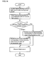
- Fig. 14 is a flowchart illustrating a displacement measurement method of the confocal measurement device, according to Embodiment 2 of the present invention.
- the displacement measurement method according to Embodiment 2 differs from the displacement measurement method according to Embodiment 1 in that instead of step S5, the process of step S5A is executed.
- the control circuit portion 25 determines the position that corresponds to the local maximum point closest to the center of the measurement range as the position of the head section 10 at the start of measurement, and positions the head section 10 at this position.
- Fig. 15 is a diagram illustrating the reason why a local maximum point is selected if there are a plurality of local maximum or minimum points in the spectral reflectance characteristics.
- a denotes the received light amount of the spectral reflectance characteristics at the wavelength indicating the peak positon of the received light intensity
- b denotes the received light amount of the spectral reflectance characteristics at the wavelength that is slightly deviated from the wavelength corresponding to the received light amount a toward the short wavelength side
- “c” denotes the received light amount of the spectral reflectance characteristics at the wavelength that is slightly deviated from the wavelength corresponding to the received light amount a toward the long wavelength side.
- the position of the head section 10 is adjusted to the position that corresponds to a local maximum point in the spectral reflectance characteristics, a measured value error will occur if the position of the head section 10 is deviated from the position corresponding to the local maximum point.
- the ratio of a change in the spectral reflectance characteristics with respect to the deviation in the position from the local maximum point is small. In other words, the ratio of a change in the received light amount (
- control circuit portion 25 positions the head section 10 at the position that corresponds to the local maximum point closest to the center of the measurement range. Accordingly, a measurement error can further be reduced.
- the measurement center distance of the head section 10 is 20 mm, and the measurement range is ⁇ 1 mm.
- a glass substrate on a surface of which a transparent thin film is partially formed was used as the measurement object 200.
- the head section 10 was moved to the transparent thin film portion of the measurement object 200 and then moved from 21 mm (moved by -1 mm with respect to the measurement center distance) to 19 mm (moved by +1 mm with respect to the measurement center distance) in the Z direction, and measured values obtained during the movement and peaks of the received light amount were plotted.
- the measurement pitch was 25 ⁇ m.
- Fig. 16 is a diagram illustrating the measurement result obtained by the measurement method according to Embodiment 2 of the present invention.
- the local maximum point closest to the measurement center is obtained with reference to Fig. 16 , it corresponds to the position where the obtained measured value is 0.125 mm.
- the control circuit portion 25 controls the moving mechanism 40 to move the head section 10 to the position at which the measured value of the confocal measurement device 100 is 0.125 mm.
- Waves of the measurement object 200 were measured. It could be confirmed that precise measurement is possible without being affected by the transparent thin film (interference film)
- an extremal point in the spectral reflectance characteristics with respect to the positions of the head section 10 is obtained.
- an extremal point may also be obtained with respect to the measured values.
- the measured values include a small error, by obtaining the measured value corresponding to the extremal point in the received light amount, and adjusting the position of the head section 10 while checking the measured value so as to be able to realize the measured value for this extremal point, it is possible to precisely match the position of the head section 10 with the extremal point in the spectral reflectance characteristics.
- the head section 10 is moved.
- the moving mechanism 40 may also move a stage 250 on which the measurement object 200 is mounted in the Z direction.
- the moving mechanism 40 is capable of moving both the head section 10 and the stage 250 concurrently or alternately. That is, the moving mechanism 40 needs only to change the distance between the head section 10 and the measurement object 200 in the measurement axis direction.
- control circuit portion that controls the moving mechanism 40 is arranged within the controller section 20, but the present invention is not necessarily limited to this.
- a configuration is also possible in which the control circuit portion that controls the moving mechanism 40 is provided outside the confocal measurement device 100.
- the specific method and configuration for obtaining the spectral reflectance characteristics of a measurement object are not limited to the above-described methods and configurations.
- an optical system as disclosed in JP 2002-81916A (for example, Fig. 6 ) may be provided separately, and the spectral reflectance characteristics may be obtained using this optical system.
- the specific method for obtaining the distance between the head section 10 and the measurement object 200 by using the obtained spectral reflectance characteristics while mitigating an error that is caused by the spectral reflectance characteristics affecting the measurement of the distance is not limited to the above-described methods.
- the distance between the head section 10 and the measurement object 200 may also be obtained based on the peak wavelength of the spectrum of light that has passed through the aperture, the spectrum of light being obtained if the spectral reflectance characteristics of the measurement object are flat and being calculated by conversion using the spectral reflectance characteristics of the measurement object that is recorded.
Abstract
Description
- The present invention relates to a displacement measurement method for measuring the displacement of a measurement object using a confocal optical system, and a displacement measurement device for performing this measurement method.
- Conventionally, various types of measurement methods and measurement devices for measuring the displacement of a measurement object have been proposed. For example,
JP 2012-208102A - Patent Document 1:
JP 2012-208102A - The confocal measurement device disclosed in
JP 2012-208102A - It is an object of the present invention to provide a displacement measurement method that can prevent the wavelength dependence of the reflectance of a measurement object from affecting measurement, and a displacement measurement device that performs this measurement method.
- According to an aspect, the present invention is directed to a displacement measurement method including the steps of: emitting light having a dispersed spectrum from a point light source; subjecting the light to axial chromatic aberration and collecting the light subjected to axial chromatic aberration on a measurement object by an optical element; passing that portion of the light collected by the optical element that is focused on the measurement object through an aperture; obtaining a spectrum of the light that has passed through the aperture; measuring a distance between the optical element and the measurement object based on a peak wavelength of the spectrum; obtaining spectral reflectance characteristics of the measurement object; and measuring the distance using the obtained spectral reflectance characteristics while mitigating an error caused by the spectral reflectance characteristics affecting the measurement of the distance.
- It is preferable that the step of obtaining spectral reflectance characteristics of the measurement object include the step of changing the distance between the optical element and the measurement object, and acquiring for each distance a local maximum point of the spectrum of the light that has passed through the aperture.
- It is preferable that the displacement measurement method further include the steps of: detecting a distance between the optical element and the measurement object at which the local maximum point of the spectrum of the light that has passed through the aperture is a local maximum point or a local minimum point in the spectral reflectance characteristics; and setting the detected distance as a reference distance between the optical element and the measurement object when the displacement is measured.
- It is preferable that if a plurality of extremal points in the spectral reflectance characteristics have been detected in the detecting step, a distance that corresponds to an extremal point, among the plurality of extremal points, that is closest to the center of a measurement range, which is a range of variation in the distance between the optical element and the measurement object, be set as the reference distance in the setting step.
- It is preferable that if a plurality of extremal points in the spectral reflectance characteristics have been detected in the detecting step, a distance that corresponds to a local maximum point, among the plurality of extremal points, that is closest to the center of a measurement range, which is a range of variation in the distance between the optical element and the measurement object, be set as the reference distance in the setting step.
- It is preferable that the displacement measurement method further include the step of detecting, while changing the position of the measurement object on which the light is collected by the optical element, a difference between the distance between the optical element and the measurement object, and the reference distance.
- According to another aspect, the present invention is directed to a displacement measurement device including: a point light source configured to emit light having a dispersed spectrum; an optical element configured to subject the light to axial chromatic aberration and collect the light subjected to axial chromatic aberration on a measurement object; an aperture through which that portion of the light collected by the optical element that is focused on the measurement object passes; a measurement section configured to obtain a spectrum of the light that has passed through the aperture and measure a distance between the optical element and the measurement object based on a peak wavelength of the spectrum. The measurement section obtains spectral reflectance characteristics of the measurement object, and measures the distance using the obtained spectral reflectance characteristics while mitigating an error caused by the spectral reflectance characteristics affecting the measurement of the distance.
- It is preferable that the measurement section change the distance between the optical element and the measurement object and acquire for each distance a local maximum point of the spectrum of the light that has passed through the aperture.
- It is preferable that the measurement section detect a distance between the optical element and the measurement object at which the local maximum point of the spectrum of the light that has passed through the aperture is a local maximum point or a local minimum point in the spectral reflectance characteristics, and set the detected distance as a reference distance between the optical element and the measurement object when the displacement is measured.
- According to the present invention, it is possible to prevent the wavelength dependence of the reflectance of a measurement object from affecting measurement. Therefore, according to the present invention, it is possible to measure the displacement of a measurement object with accuracy even when the reflectance of a measurement object strongly depends on a wavelength.
-
- Fig. 1
- is a schematic diagram illustrating a configuration of a confocal measurement device that serves as a displacement measurement device according to an embodiment of the present invention.
- Fig. 2
- is a diagram illustrating a first example relating to measuring the relative position to a transparent thin film of a
measurement object 200. - Fig. 3
- is a waveform chart illustrating the relationship between the positions of a head section (sensor head) and the received light waveforms in a spectrum measurement section.
- Fig. 4
- is a graph illustrating the relationship between the positions of the head section 10 (sensor head) and the measured values in the case where the received light waveforms as shown in
Fig. 3 occurs. - Fig. 5
- is a graph illustrating the relationship between the positions of the head section 10 (sensor head) and the measured value errors.
- Fig. 6
- is a diagram illustrating the relationship between the received light amounts (peak values of the received light intensity that are obtained based on the received light waveforms shown in
Fig. 4 ) and the measured value errors. - Fig. 7
- is a diagram illustrating the reason why a measured value error occurs.
- Fig. 8
- is a diagram illustrating a second example relating to measuring the relative position to the
measurement object 200. - Fig. 9
- is a diagram illustrating the measurement result obtained when the displacement of a measurement object is measured using the configuration shown in
Fig. 8 . - Fig. 10
- is a diagram illustrating a third example relating to measuring the relative position to a transparent thin film of the
measurement object 200. - Fig. 11
- is a diagram illustrating a fourth example relating to measuring the relative position to a transparent thin film of the
measurement object 200. - Fig. 12
- is a diagram illustrating the principle of displacement measurement according to
Embodiment 1 of the present invention. - Fig. 13
- is a flowchart illustrating a displacement measurement method of a confocal measurement device, according to
Embodiment 1 of the present invention. - Fig. 14
- is a flowchart illustrating a displacement measurement method of the confocal measurement device, according to
Embodiment 2 of the present invention. - Fig. 15
- is a diagram illustrating the reason why a local maximum point is selected if there are a plurality of local maximum or minimum points in the spectral reflectance characteristics.
- Fig. 16
- is a diagram illustrating the measurement result obtained by the measurement method according to
Embodiment 2 of the present invention. - Fig. 17
- is a diagram illustrating an example of another configuration of the confocal measurement device according to the embodiments of the present invention.
- Hereinafter, embodiments of the present invention will be described in detail with reference to the drawings. Note that in the following description, the same reference numerals are given to the same components, and detailed descriptions thereof will be omitted.
-
Fig. 1 is a schematic diagram illustrating a configuration of a confocal measurement device that is realized as a displacement measurement device according to an embodiment of the present invention. Theconfocal measurement device 100 illustrated inFig. 1 is a displacement measurement device that measures the displacement of ameasurement object 200 using a confocal optical system. - The
confocal measurement device 100 is provided with ahead section 10, anoptical fiber 11, acontroller section 20, amonitor unit 30, and a movingmechanism 40. Thehead section 10 includes a confocal optical system. Thehead section 10 and thecontroller section 20 are optically connected to each other via theoptical fiber 11. Themonitor unit 30 displays signals output from thecontroller section 20. - The
head section 10 is provided with adiffraction lens 1, anobjective lens 2, and acollective lens 3. Thediffraction lens 1 has a focal length that is larger than a difference between the distance between thediffraction lens 1 and theobjective lens 2, and the focal length of theobjective lens 2. - The
diffraction lens 1 is an optical element that subjects light emitted from a light source that emits light having a plurality of wavelengths, to axial chromatic aberration in an optical axis direction (for example, a white light source) (described later). Optical axis A is the optical axis of thediffraction lens 1. Note that the optical axis A of thediffraction lens 1 corresponds to the optical axis of light emitted from theoptical fiber 11 and the optical axis of theobjective lens 2. Furthermore, the direction of the optical axis A of thediffraction lens 1 corresponds to the direction (Z direction) of the measurement axis of theconfocal measurement device 100. - Fine projections and depressions in, for example, a kinoform shape, a binary shape (for example, the shape of steps or stairs), or the like are periodically formed on one surface of the
diffraction lens 1. Alternatively, an amplitude-type zone plate that periodically changes light transmittance may be formed on one surface of thediffraction lens 1. Note that the configuration of thediffraction lens 1 is not limited to the above-described configurations. - The
diffraction lens 1 may have a configuration in which a pattern that creates chromatic aberration in an optical axis direction is formed on a substrate made from a single material, such as a glass or a resin, for example. Alternatively, thediffraction lens 1 may be constituted by, for example, a glass substrate layer and a resin layer. The resin layer can be obtained by coating the glass substrate with an ultraviolet curable resin, pressing a mold of a desired pattern against the glass substrate surface coated with the ultraviolet curable resin, and irradiating the glass substrate with ultraviolet light to cure the ultraviolet curable resin. According to this method, low-cost manufacturing can be realized. Moreover, since a large part of thediffraction lens 1 is made from the glass substrate, whose shape changes little due to an ambient temperature, thediffraction lens 1 made from a glass substrate layer and a resin layer also has an advantage in terms of temperature characteristics. Note that the optical element that creates axial chromatic aberration is not limited to thediffraction lens 1, and may be realized, for example, by a combination of a plurality of lenses. - The
objective lens 2 is an optical element that collects the light that was subjected to chromatic aberration by thediffraction lens 1 on themeasurement object 200. Theobjective lens 2 collimates light reflected from themeasurement object 200 into parallel light. The collimated light is incident on thediffraction lens 1. Note that in the configuration illustrated inFig. 1 , theobjective lens 2 is disposed closer to themeasurement object 200 than thediffraction lens 1. However, the disposition relationship between theobjective lens 2 and thediffraction lens 1 is not limited to this. - The following will describe the case where a white light source is employed as a light source that emits light having a plurality of wavelengths. Light emitted from the white light source is guided to the
head section 10 via theoptical fiber 11. In order for the light exiting theoptical fiber 11 to efficiently be used in thediffraction lens 1, it is necessary that the numerical aperture (NA) of theoptical fiber 11 and the numerical aperture of thediffraction lens 1 match each other. Therefore, thecollective lens 3 is provided between theoptical fiber 11 and thediffraction lens 1 to perform adjustment for matching the numerical aperture of theoptical fiber 11 with the numerical aperture of thediffraction lens 1. - The
optical fiber 11 is a light path from thehead section 10 to thecontroller section 20 and also functions as an aperture. In other words, that portion of the light collected by theobjective lens 2 that is focused on themeasurement object 200 is to be focused on the aperture portion of theoptical fiber 11. Accordingly, theoptical fiber 11 functions as an aperture through which light having a wavelength at which the light is not focused on themeasurement object 200 does not pass but light focused on themeasurement object 200 passes. Using theoptical fiber 11 as the light path from thehead section 10 to thecontroller section 20 eliminates the need of providing a pinhole. - The
confocal measurement device 100 may also have a configuration in which theoptical fiber 11 is not used as the light path from thehead section 10 to thecontroller section 20. However, using theoptical fiber 11 as the light path makes it possible to flexibly move thehead section 10 with respect to thecontroller section 20. If theoptical fiber 11 is not used as the light path from thehead section 10 to thecontroller section 20, theconfocal measurement device 100 needs to have a pinhole. However, by using theoptical fiber 11, theconfocal measurement device 100 does not need to have a pinhole. - The
controller section 20, which serves as a measurement section, is provided with a white LED (Light Emitting Diode) 21, which is a white light source, a branchedoptical fiber 22, aspectroscope 23, animaging element 24, and acontrol circuit portion 25. Although thewhite LED 21 is used as a point light source that emits white light having a dispersed spectrum, another light source may be used as long as it is a point light source that can emit white light having a dispersed spectrum over the visible light wavelength range. - The branched
optical fiber 22 includes oneoptical fiber 22a on the side of connecting to theoptical fiber 11 and twooptical fibers optical fiber 22b is optically connected to thewhite LED 21, and theoptical fiber 22c is optically connected to thespectroscope 23. Accordingly, the branchedoptical fiber 22 can guide light emitted from thewhite LED 21 to theoptical fiber 11, and can guide light returned from thehead section 10 via theoptical fiber 11 to thespectroscope 23. - The
spectroscope 23 includes aconcave mirror 23a that reflects light returned from thehead section 10, a grating 23b on which the light reflected by theconcave mirror 23a is incident, and acollective lens 23c that collects the light emitted from the grating 23b. Thespectroscope 23 may have any configuration, such as the Czerny-Turner type, the Littrow type, or the like, as long as it can change the focal position of light returned from thehead section 10 on theimaging element 24 depending on its wavelength. - The
imaging element 24 measures the intensity of light that is emitted from thespectroscope 23. Theimaging element 24 is, for example, a line complementary metal oxide semiconductor (CMOS) or a line charge coupled device (CCD). In theconfocal measurement device 100, thespectroscope 23 and theimaging element 24 constitute a spectrum measurement section that measures the intensity of light returned from thehead section 10 with respect to each wavelength, that is, obtains the spectrum of light returned from thehead section 10, so as to specify the wavelength of the focused light based on the peak value of the intensity, or the like. By obtaining the relationship between the wavelength of the light that is to be focused and the displacement of themeasurement object 200 in advance, it is possible to measure the displacement of themeasurement object 200. The measurement section may also be constituted only by theimaging element 24 such as a CCD as long as it can measure the intensity of light returned from thehead section 10 with respect to each wavelength. Theimaging element 24 may also be a two-dimensional CMOS or a two-dimensional CCD. - The
control circuit portion 25 is constituted by a circuit for controlling operations of thewhite LED 21, theimaging element 24, the movingmechanism 40, and the like. - The
monitor unit 30 displays signals output by theimaging element 24. For example, themonitor unit 30 plots a spectrum waveform of light returned from thehead section 10, and displays that the displacement of the measurement object is 123.45 µm, for example. - The moving
mechanism 40 moves, under the control of thecontrol circuit portion 25, thehead section 10 in the direction (Z direction) of the measurement axis of theconfocal measurement device 100, and positions thehead section 10. With the movingmechanism 40, it is possible to change the distance between thehead section 10 and themeasurement object 200. - The
control circuit portion 25 acquires, from the spectrum measurement section, a signal indicating the amount of light (received light amount) received by the spectrum measurement section while changing the distance between thehead section 10 and themeasurement object 200 using the movingmechanism 40. Note here that "received light amount" refers to peak values of the intensity of the received light that are obtained based on a waveform of the received light acquired by the spectrum measurement section. Thecontrol circuit portion 25 positions thehead section 10 at a position that corresponds to an extremal point of the waveform that indicates the change in the received light amount with respect to the distance between thehead section 10 and themeasurement object 200. The distance between thehead section 10 and themeasurement object 200 at that time serves as a reference distance between thehead section 10 and themeasurement object 200 when the displacement of themeasurement object 200 is measured. - "Extremal point of the received light amount" refers to a local maximum point or local minimum point in the waveform of the received light amount. For example, a point at which the amount of change in the received light amount with respect to the distance is a predetermined value or less can be defined as a local maximum point or local minimum point. "Local maximum point" refers to, for example, a point at which the amount of change in the received light amount with respect to the distance is a gradually decreasing positive value and eventually takes on a predetermined value or less (ideally, 0). "Local minimum point" refers to, for example, a point at which the amount of change in the received light amount with respect to the distance is a gradually increasing negative value and eventually takes on a predetermined value (ideally, 0) (i.e. an absolute value of the amount of change decreases).
- The
confocal measurement device 100, which is a displacement measurement device according to the embodiments of the present invention, measures the displacement of themeasurement object 200 based on a wavelength at which the intensity of received light reflected from themeasurement object 200 is the largest. If the reflectance of the measurement object depends little on the wavelength, it is possible to precisely measure the distance. However, in the case of measurement in which a substrate on which an interference film is formed for example, the reflectance thereof largely varies depending on the wavelength. Accordingly, the problem arises that it is difficult to precisely measure the displacement. - In the embodiments of the present invention, prior to measuring the displacement, a waveform of the amount of light received by the measurement section is acquired while changing the distance between the
head section 10 and themeasurement object 200 using the movingmechanism 40. Thehead section 10 is positioned at the position that corresponds to a local maximum point or local minimum point of the received light amount. Accordingly, even if the reflectance of themeasurement object 200 strongly depends on the wavelength, it is possible to measure the displacement of the measurement object with accuracy. - In this regard, the following will describe first the problems that may be caused when measuring the displacement of a measurement object whose reflectance largely varies depending on a wavelength, and then the solutions of those problems that can be achieved by the
confocal measurement device 100 according to the embodiments of the present invention. -
Fig. 2 is a diagram illustrating a first example relating to measuring the relative position to a transparent thin film of themeasurement object 200. The measurement of the relative position to the transparent thin film of themeasurement object 200 corresponds to measurement of displacement. As shown inFig. 2 , themeasurement object 200 is constituted by asubstrate 200a and a transparentthin film 200b that is formed on a surface of thesubstrate 200a. At the start of measurement, the distance between themeasurement object 200 and the head section 10 (sensor head) is set to a predetermined distance. The distance from the position of thehead section 10 to themeasurement object 200 at that time serves as a reference distance. In this embodiment, thehead section 10 is movable in the positive Z direction and the negative Z direction with the reference distance defined as a measurement center distance. The range of movement of thehead section 10 is the "measurement range" of theconfocal measurement device 100. - When light is projected onto the
measurement object 200 from thehead section 10, rays of the light are reflected not only on the surface of the transparentthin film 200b (boundary between the transparentthin film 200b and air) but also on the boundary between the transparentthin film 200b and thesubstrate 200a. These rays of reflected light interfere with each other. - In this embodiment, the
head section 10 irradiates themeasurement object 200 with white light. It is known that the intensity of interfering light varies depending on not only the thickness of the transparent thin film but also the light wavelength (seeJP 2002-819196A Fig. 2 , by irradiating the substrate on which the transparent thin film is formed with white light so as to acquire a received light waveform of the reflected light, it is possible to obtain a spectrum of the intensity of the received light that varies depending on a wavelength (seeJP 2002-819196A Fig. 7 , for example). -
Fig. 3 is a waveform chart illustrating the relationship between the positions of a head section (sensor head) and the waveform of light received by the spectrum measurement section (received light waveform). As shown inFig. 3 , the peak heights of the intensity of the received light (received light intensity) vary due to the influence of interference. InFig. 3 , a plurality of received light waveforms are indicated by different types of lines. -
Fig. 4 is a graph illustrating the relationship between the positions of the head section 10 (sensor head) and the measured values in the case where the received light waveforms as shown inFig. 3 occur. The graph shown inFig. 4 is the result of the measured values obtained based on the peak positions (seeFig. 3 ) of the received light waveforms, and the horizontal axis thereof indicates the positions of thehead section 10 and the vertical axis thereof indicates the measured values. The relationship of the measured values to the sensor head positions is originally a linear relationship (sensor head positions = measured values). However, as shown inFig. 4 , the relationship of the measured values to the sensor head positions is indicated as a line that slightly undulates compared to a straight line, due to the influence of interference. -
Fig. 5 is a graph illustrating the relationship between the positions of the head section 10 (sensor head) and the measured value errors. "Measured value errors" refers to differences between the original relationship of measured values to sensor head positions (straight line), and the actual relationship (wavy line). Originally, irrespective of the position of the head section 10 (sensor head), the measured value error should be 0. However, as shown inFig. 5 , errors occur that are deviated in the positive and negative directions in an alternating manner depending on the sensor head position. Such errors are caused due to the influence of interference. -
Fig. 6 is a diagram illustrating the relationship between the received light amounts (peak values of the received light intensity that are obtained based on the received light waveform shown inFig. 4 ) and the measured value errors. As shown inFig. 6 , the measured value error is almost 0 at any extremal point of the received light amount, that is, a local maximum point or local minimum point of the waveform of the received light amount. Note that the situation that the measured value error is 0 means that the measured value and the true value are equal to each other. -
Fig. 7 is a diagram illustrating the reason why a measured value error occurs. As shown inFig. 7 , the received light waveform can be obtained based on the product of multiplying the spectral reflectance characteristics by the confocal waveform. The "spectral reflectance characteristics" can be expressed as the wavelength dependence of the amount of the reflected light received by the spectrum measurement section. If no transparent thin film is provided, the spectral reflectance characteristics show only a gradual change with respect to a wavelength. Accordingly, inFig. 7 , no spectral reflectance characteristics are shown for the case where no transparent thin film is provided. - If no transparent thin film is provided, the confocal waveform and the received light waveform have the same wavelength at which the received light intensity reaches the peak. Therefore, the measurement error is 0. On the other hand, in the case of a substrate on a surface of which a transparent thin film is formed, the amount of the received reflected light to a wavelength largely varies due to interference. If there is a change (inclination) in the spectral reflectance characteristics at the workpiece height (wavelength) at which the confocal waveform reaches the peak, a difference in the wavelength at which the received light intensity reaches the peak is caused between the received light waveform and the confocal waveform due to the product obtained by multiplying the spectral reflectance characteristics by the confocal waveform. This difference corresponds to the measured value error.
-
Fig. 8 is a diagram illustrating a second example relating to measuring the relative position to themeasurement object 200.Fig. 9 is a diagram illustrating the measurement result obtained by measuring the displacement of the measurement object using the configuration shown inFig. 8 . - As shown in
Figs. 8 and 9 , themeasurement object 200 includes the transparentthin film 200b in a part of the surface of thesubstrate 200a. In other words, the surface of themeasurement object 200 includes a mixture of the part in which the transparentthin film 200b is present and the part in which no transparentthin film 200b is present. - For investigation of, for example, a warpage or wave of the substrate, the height of the
measurement object 200 is measured in its substrate (in the X direction, for example). In this case, as shown inFig. 9 , in the part in which the transparentthin film 200b is present, a difference in height that is equal to or larger than the thickness of the transparentthin film 200b is measured due to the influence of interference. Furthermore, the value measured for the difference in height varies depending on the height position of thehead section 10. In other words, there is the problem that the value measured for the difference in height varies depending on a wavelength that is used. -
Fig. 10 is a diagram illustrating a third example relating to measuring the relative position to a transparent thin film of themeasurement object 200. As shown inFig. 10 , aglass substrate 201 and amask 202 are disposed so that the gap between theglass substrate 201 and themask 202 is a predetermined distance. Theglass substrate 201 includes, on its surface, a transparentthin film 201b. In this configuration, it is investigated whether or not the gap between theglass substrate 201 and themask 202 is within a standard range that includes the above-described predetermined distance. -
Fig. 11 is a diagram illustrating a fourth example relating to measuring the relative position to the transparent thin film of themeasurement object 200. As shown inFig. 11 , thesubstrate 200a is a transparent substrate such as a glass. In this example, the thickness of thesubstrate 200a (transparent substrate) is measured. - As shown in
Fig. 10 , when measuring the gap between the surface on which the transparent thin film is formed and the surface on which no transparent thin film is formed, there may be the problem that the value measured for this gap deviates from the actual value due to the influence of interference. Similarly, in the example shown inFig. 11 , when measuring the thickness of the transparent substrate, there may also be the problem that the value measured for the thickness of the transparent substrate deviates from the actual value due to the influence of interference. There may further be the problem that the value measured for the gap shown inFig. 10 or the value measured for the thickness of the transparent substrate shown inFig. 11 varies depending on the position in the Z direction of thehead section 10. - According to the embodiments of the present invention, the above-described problems are solved by selecting a wavelength at which there is little influence due to interference and then measuring the displacement. Hereinafter, the embodiments will be described in detail.
- Referring again to
Fig. 1 , inEmbodiment 1, thehead section 10 is moved in the Z direction by the movingmechanism 40, and reflected light is received by the spectrum measurement section. Thecontrol circuit portion 25 receives, from the spectrum measurement section, a signal indicating the amount of the received light. This signal indicates the spectral reflectance characteristics (interference waveform). - The
control circuit portion 25 controls the movingmechanism 40 to adjust the distance between thehead section 10 and themeasurement object 200 so that the distance corresponds to a local maximum point or local minimum point of the amount of the received light in the spectral reflectance characteristics (interference waveform). By changing the position of thehead section 10 in the above-described manner, the distance between thehead section 10 and themeasurement object 200 is adjusted. -
Fig. 12 is a diagram illustrating the principle of displacement measurement according toEmbodiment 1 of the present invention. As shown inFig. 12 , a change in the received light amount with respect to the workpiece height (wavelength) is small at the extremal points (local maximum point or local minimum point) in the spectral reflectance characteristics, and the received light amount can be deemed as almost constant at these points. The received light waveform can be obtained based on the product of multiplying the spectral reflectance characteristics by the confocal waveform. Accordingly, it is possible to ensure that the received light waveform and the confocal waveform have the same wavelength at which the received light intensity reaches the peak. - According to
Embodiment 1, it is thus possible to precisely measure the distance between thehead section 10 and the transparentthin film 200b. This makes it possible to precisely measure a warpage or wave of the substrate on which a transparent thin film is formed, the gap between the substrate and the mask, the thickness of the transparent substrate, and the like. -
Fig. 13 is a flowchart illustrating a displacement measurement method of the confocal measurement device, according toEmbodiment 1 of the present invention. The procedure shown in this flowchart is executed mainly by thecontrol circuit portion 25. As shown inFig. 13 , in step S1, thecontrol circuit portion 25 lets the movingmechanism 40 move thehead section 10, and acquires, from the spectrum measurement section, a signal indicating the amount of light received by the spectrum measurement section (that is, a signal indicating the spectral reflectance characteristics). - In step S2, the
control circuit portion 25 detects, based on the signal received from the spectrum measurement section, any local maximum points or local minimum points of the received light amount within a measurement range. - In step S3, the
control circuit portion 25 determines whether or not there are a plurality of detected local maximum or minimum points of the received light amount. If there is exactly one local maximum point or local minimum point of the received light amount within the measurement range, the position that corresponds to this local maximum point or local minimum point is set as the position of thehead section 10 at the start of measurement in step S4. The distance between thehead section 10 and themeasurement object 200 at that time is the distance at the start of measurement, that is, the measurement center distance (that corresponds to the "reference distance" of the present invention). - On the other hand, if there are a plurality of local maximum or minimum points of the received light amount within the measurement range, the
control circuit portion 25 sets the position that corresponds to the local maximum point or local minimum point that is closest to the center of the measurement range as the position of thehead section 10 at the start of measurement in step S5. Thus, the measurement center distance is determined. - In steps S4 or S5, the
control circuit portion 25 controls the movingmechanism 40 to position thehead section 10 at the position at which the distance between thehead section 10 and themeasurement object 200 is the measurement center distance. After the procedure in step S4 or S5, the displacement is measured in step S6. For example, any one of the foregoing first to third measurement examples is executed. Note that in the case of the third measurement example, while themeasurement object 200 is scanned in the X direction so that the position of themeasurement object 200 on which light is collected by thehead section 10 is changed, a difference between the distance between thehead section 10 and themeasurement object 20, and the "reference distance" is detected. - According to
Embodiment 1, prior to measuring the displacement, thehead section 10 is moved in the measurement axis direction. Based on the amount of light received by the measurement section, thehead section 10 is positioned at a position that corresponds to a local maximum point or local minimum point (that is, a local maximum point or local minimum point of the received light amount) of the waveform of the spectral reflectance characteristics. Accordingly, it is possible to prevent the spectral reflectance characteristics from affecting the displacement measurement, allowing precise measurement. Accordingly, it is possible to precisely measure, for example, the relative position to the transparent thin film of themeasurement object 200. - Moreover, according to
Embodiment 1, if there are a plurality of local maximum or minimum points of the received light amount in the measurement range, thehead section 10 is positioned at the position that corresponds to the local maximum point or local minimum point of the received light amount that is closest to the center of measurement. Accordingly, measurement is possible using the wavelength at which the emission intensity of a white light source is high, and thus it is possible to increase the S/N ratio of a received-light signal from the spectrum measurement section. As a result, more precise measurement is possible. -
Fig. 14 is a flowchart illustrating a displacement measurement method of the confocal measurement device, according toEmbodiment 2 of the present invention. As shown inFigs. 13 and14 , the displacement measurement method according toEmbodiment 2 differs from the displacement measurement method according toEmbodiment 1 in that instead of step S5, the process of step S5A is executed. In step S5A, thecontrol circuit portion 25 determines the position that corresponds to the local maximum point closest to the center of the measurement range as the position of thehead section 10 at the start of measurement, and positions thehead section 10 at this position. -
Fig. 15 is a diagram illustrating the reason why a local maximum point is selected if there are a plurality of local maximum or minimum points in the spectral reflectance characteristics. As shown inFig. 15 , "a" denotes the received light amount of the spectral reflectance characteristics at the wavelength indicating the peak positon of the received light intensity, "b" denotes the received light amount of the spectral reflectance characteristics at the wavelength that is slightly deviated from the wavelength corresponding to the received light amount a toward the short wavelength side, and "c" denotes the received light amount of the spectral reflectance characteristics at the wavelength that is slightly deviated from the wavelength corresponding to the received light amount a toward the long wavelength side. - If the position of the
head section 10 is adjusted to the position that corresponds to a local maximum point in the spectral reflectance characteristics, a measured value error will occur if the position of thehead section 10 is deviated from the position corresponding to the local maximum point. However, the ratio of a change in the spectral reflectance characteristics with respect to the deviation in the position from the local maximum point is small. In other words, the ratio of a change in the received light amount (|b-a|/a or |c-a|/a) is small. Accordingly, a measurement error can be reduced. - On the other hand, if the position of the
head section 10 is adjusted to the position that corresponds to a local minimum point in the spectral reflectance characteristics, an error will occur if the position of thehead section 10 is deviated from the position corresponding to the local minimum point. In this case, the ratio of a change in the waveform in the spectral reflectance characteristics is abrupt. That is, this ratio of a change in the received light amount (|b-a|/a or |c-a|/a) is larger than the ratio of a change in the received light amount in the vicinity of the local maximum point in the spectral reflectance characteristics. Accordingly, a measurement error is likely to be large. - According to
Embodiment 2, thecontrol circuit portion 25 positions thehead section 10 at the position that corresponds to the local maximum point closest to the center of the measurement range. Accordingly, a measurement error can further be reduced. - Hereinafter, results obtained by measuring the displacement according to the foregoing embodiments will be described. In the examples, waves of a transparent substrate were measured.
- The measurement center distance of the
head section 10 is 20 mm, and the measurement range is ± 1 mm. A glass substrate on a surface of which a transparent thin film is partially formed was used as themeasurement object 200. - The
head section 10 was moved to the transparent thin film portion of themeasurement object 200 and then moved from 21 mm (moved by -1 mm with respect to the measurement center distance) to 19 mm (moved by +1 mm with respect to the measurement center distance) in the Z direction, and measured values obtained during the movement and peaks of the received light amount were plotted. The measurement pitch was 25 µm. -
Fig. 16 is a diagram illustrating the measurement result obtained by the measurement method according toEmbodiment 2 of the present invention. When the local maximum point closest to the measurement center is obtained with reference toFig. 16 , it corresponds to the position where the obtained measured value is 0.125 mm. - The
control circuit portion 25 controls the movingmechanism 40 to move thehead section 10 to the position at which the measured value of theconfocal measurement device 100 is 0.125 mm. - Waves of the measurement object 200 (substrate) were measured. It could be confirmed that precise measurement is possible without being affected by the transparent thin film (interference film)
- Note that in
Embodiment 1, an extremal point in the spectral reflectance characteristics with respect to the positions of thehead section 10 is obtained. However, as shown inFig. 16 , an extremal point may also be obtained with respect to the measured values. At that time, although the measured values include a small error, by obtaining the measured value corresponding to the extremal point in the received light amount, and adjusting the position of thehead section 10 while checking the measured value so as to be able to realize the measured value for this extremal point, it is possible to precisely match the position of thehead section 10 with the extremal point in the spectral reflectance characteristics. - Furthermore, in the foregoing embodiments, the
head section 10 is moved. However, as shown inFig. 17 , the movingmechanism 40 may also move astage 250 on which themeasurement object 200 is mounted in the Z direction. Alternatively, it is also possible that the movingmechanism 40 is capable of moving both thehead section 10 and thestage 250 concurrently or alternately. That is, the movingmechanism 40 needs only to change the distance between thehead section 10 and themeasurement object 200 in the measurement axis direction. - Furthermore, in the foregoing embodiments, the control circuit portion that controls the moving
mechanism 40 is arranged within thecontroller section 20, but the present invention is not necessarily limited to this. A configuration is also possible in which the control circuit portion that controls the movingmechanism 40 is provided outside theconfocal measurement device 100. - Moreover, the specific method and configuration for obtaining the spectral reflectance characteristics of a measurement object are not limited to the above-described methods and configurations. For example, an optical system as disclosed in
JP 2002-81916A Fig. 6 ) may be provided separately, and the spectral reflectance characteristics may be obtained using this optical system. - Moreover, the specific method for obtaining the distance between the
head section 10 and themeasurement object 200 by using the obtained spectral reflectance characteristics while mitigating an error that is caused by the spectral reflectance characteristics affecting the measurement of the distance is not limited to the above-described methods. For example, the distance between thehead section 10 and themeasurement object 200 may also be obtained based on the peak wavelength of the spectrum of light that has passed through the aperture, the spectrum of light being obtained if the spectral reflectance characteristics of the measurement object are flat and being calculated by conversion using the spectral reflectance characteristics of the measurement object that is recorded. - The embodiments disclosed herein are examples in all aspects and are not to be construed as restricting. The scope of the present invention is shown by the claims rather than the description above, and is intended to cover all equivalents to the claims and all modifications in the claims.
- 1 ... Diffraction lens, 2 ... Objective lens, 3, 23c ... Collective lens, 10 ... Head section, 11, 22a to 22c ... Optical fiber, 20 ... Controller section, 21 ... White LED, 22 ... branched optical fiber, 23 ... Spectroscope, 23a ... Concave mirror, 23b ... Grating, 24 ... Imaging element, 25 ... Control circuit portion, 30 ... Monitor, 40 ... Moving mechanism, 100 ... Confocal measurement device, 200 ... Measurement object, 200a ... Substrate, 200b, 201b ... Transparent thin film, 201 ... Glass substrate, 202 ... Mask, A ... Optical axis
Claims (10)
- A displacement measurement method comprising the steps of:emitting light having a dispersed spectrum from a point light source;subjecting the light to axial chromatic aberration and collecting the light subjected to axial chromatic aberration on a measurement object by an optical element;passing that portion of the light collected by the optical element that is focused on the measurement object through an aperture;obtaining a spectrum of the light that has passed through the aperture;measuring a distance between the optical element and the measurement object based on a peak wavelength of the spectrum;obtaining spectral reflectance characteristics of the measurement object; andmeasuring the distance using the obtained spectral reflectance characteristics while mitigating an error caused by the spectral reflectance characteristics affecting the measurement of the distance.
- The displacement measurement method according to claim 1,
wherein the step of obtaining spectral reflectance characteristics of the measurement object includes the step of:changing the distance between the optical element and the measurement object, and acquiring for each distance a local maximum point of the spectrum of the light that has passed through the aperture. - The displacement measurement method according to claim 1,
further comprising the steps of:detecting a distance between the optical element and the measurement object at which the local maximum point of the spectrum of the light that has passed through the aperture is a local maximum point or a local minimum point in the spectral reflectance characteristics; andsetting the detected distance as a reference distance between the optical element and the measurement object when the displacement is measured. - The displacement measurement method according to claim 3,
wherein if a plurality of extremal points in the spectral reflectance characteristics have been detected in the detecting step, a distance that corresponds to a local maximum point, among the plurality of extremal points, that is closest to the center of a measurement range, which is a range of variation in the distance between the optical element and the measurement object, is set as the reference distance in the setting step. - The displacement measurement method according to claim 3,
wherein if a plurality of extremal points in the spectral reflectance characteristics have been detected in the detecting step, a distance that corresponds to an extremal point, among the plurality of extremal points, that is closest to the center of a measurement range, which is a range of variation in the distance between the optical element and the measurement object, is set as the reference distance in the setting step. - The displacement measurement method according to claim 5,
wherein if a plurality of extremal points in the spectral reflectance characteristics have been detected in the detecting step, a distance that corresponds to a local maximum point, among the plurality of extremal points, that is closest to the center of a measurement range, which is a range of variation in the distance between the optical element and the measurement object, is set as the reference distance in the setting step. - The displacement measurement method according to claim 5,
further comprising the step of
detecting, while changing the position of the measurement object on which the light is collected by the optical element, a difference between the distance between the optical element and the measurement object, and the reference distance. - A displacement measurement device comprising:a point light source configured to emit light having a dispersed spectrum;an optical element configured to subject the light to axial chromatic aberration and collect the light subjected to axial chromatic aberration on a measurement object;an aperture through which that portion of the light collected by the optical element that is focused on the measurement object passes;a measurement section configured to obtain a spectrum of the light that has passed through the aperture and measure a distance between the optical element and the measurement object based on a peak wavelength of the spectrum,wherein the measurement section obtains spectral reflectance characteristics of the measurement object, and measures the distance using the obtained spectral reflectance characteristics while mitigating an error caused by the spectral reflectance characteristics affecting the measurement of the distance.
- The displacement measurement device according to claim 8,
wherein the measurement section changes the distance between the optical element and the measurement object, and acquires for each distance a local maximum point of the spectrum of the light that has passed through the aperture. - The displacement measurement device according to claim 8,
wherein the measurement section detects a distance between the optical element and the measurement object at which the local maximum point of the spectrum of the light that has passed through the aperture is a local maximum point or a local minimum point in the spectral reflectance characteristics, and sets the detected distance as a reference distance between the optical element and the measurement object when the displacement is measured.
Applications Claiming Priority (2)
| Application Number | Priority Date | Filing Date | Title |
|---|---|---|---|
| JP2012271349A JP6044315B2 (en) | 2012-12-12 | 2012-12-12 | Displacement measuring method and displacement measuring apparatus |
| PCT/JP2013/080795 WO2014091865A1 (en) | 2012-12-12 | 2013-11-14 | Method and device for measuring displacement |
Publications (3)
| Publication Number | Publication Date |
|---|---|
| EP2933599A1 true EP2933599A1 (en) | 2015-10-21 |
| EP2933599A4 EP2933599A4 (en) | 2016-08-17 |
| EP2933599B1 EP2933599B1 (en) | 2020-03-11 |
Family
ID=50934161
Family Applications (1)
| Application Number | Title | Priority Date | Filing Date |
|---|---|---|---|
| EP13863540.4A Active EP2933599B1 (en) | 2012-12-12 | 2013-11-14 | Method and device for measuring displacement |
Country Status (5)
| Country | Link |
|---|---|
| EP (1) | EP2933599B1 (en) |
| JP (1) | JP6044315B2 (en) |
| CN (1) | CN104797904B (en) |
| TW (1) | TWI480501B (en) |
| WO (1) | WO2014091865A1 (en) |
Cited By (1)
| Publication number | Priority date | Publication date | Assignee | Title |
|---|---|---|---|---|
| US11674794B2 (en) | 2016-03-24 | 2023-06-13 | Omron Corporation | Optical measurement device |
Families Citing this family (64)
| Publication number | Priority date | Publication date | Assignee | Title |
|---|---|---|---|---|
| US10772506B2 (en) * | 2014-07-07 | 2020-09-15 | Align Technology, Inc. | Apparatus for dental confocal imaging |
| US9693839B2 (en) | 2014-07-17 | 2017-07-04 | Align Technology, Inc. | Probe head and apparatus for intraoral confocal imaging using polarization-retarding coatings |
| US9675430B2 (en) | 2014-08-15 | 2017-06-13 | Align Technology, Inc. | Confocal imaging apparatus with curved focal surface |
| WO2016030227A1 (en) * | 2014-08-29 | 2016-03-03 | Asml Netherlands B.V. | Method for controlling a distance between two objects, inspection apparatus and method |
| US9610141B2 (en) | 2014-09-19 | 2017-04-04 | Align Technology, Inc. | Arch expanding appliance |
| US10449016B2 (en) | 2014-09-19 | 2019-10-22 | Align Technology, Inc. | Arch adjustment appliance |
| US9744001B2 (en) | 2014-11-13 | 2017-08-29 | Align Technology, Inc. | Dental appliance with cavity for an unerupted or erupting tooth |
| US10504386B2 (en) | 2015-01-27 | 2019-12-10 | Align Technology, Inc. | Training method and system for oral-cavity-imaging-and-modeling equipment |
| US9958266B2 (en) * | 2015-07-09 | 2018-05-01 | Mitutoyo Corporation | Chromatic range sensor including dynamic intensity compensation function |
| US10248883B2 (en) | 2015-08-20 | 2019-04-02 | Align Technology, Inc. | Photograph-based assessment of dental treatments and procedures |
| US11931222B2 (en) | 2015-11-12 | 2024-03-19 | Align Technology, Inc. | Dental attachment formation structures |
| US11554000B2 (en) | 2015-11-12 | 2023-01-17 | Align Technology, Inc. | Dental attachment formation structure |
| US11596502B2 (en) | 2015-12-09 | 2023-03-07 | Align Technology, Inc. | Dental attachment placement structure |
| US11103330B2 (en) | 2015-12-09 | 2021-08-31 | Align Technology, Inc. | Dental attachment placement structure |
| JP6615604B2 (en) * | 2015-12-25 | 2019-12-04 | 株式会社キーエンス | Confocal displacement meter |
| JP6654893B2 (en) * | 2015-12-25 | 2020-02-26 | 株式会社キーエンス | Confocal displacement meter |
| JP6779234B2 (en) * | 2015-12-25 | 2020-11-04 | 株式会社キーエンス | Confocal displacement meter |
| TWI606191B (en) * | 2016-01-04 | 2017-11-21 | Linear motion mechanism | |
| JP6725988B2 (en) | 2016-01-26 | 2020-07-22 | 大塚電子株式会社 | Thickness measuring device and thickness measuring method |
| US10383705B2 (en) | 2016-06-17 | 2019-08-20 | Align Technology, Inc. | Orthodontic appliance performance monitor |
| US10470847B2 (en) | 2016-06-17 | 2019-11-12 | Align Technology, Inc. | Intraoral appliances with sensing |
| US10507087B2 (en) | 2016-07-27 | 2019-12-17 | Align Technology, Inc. | Methods and apparatuses for forming a three-dimensional volumetric model of a subject's teeth |
| KR102595753B1 (en) | 2016-07-27 | 2023-10-30 | 얼라인 테크널러지, 인크. | Intraoral scanner with dental diagnostics capabilities |
| US10120196B2 (en) * | 2016-09-30 | 2018-11-06 | National Taiwan University Of Science And Technology | Optical device |
| CN113648088B (en) | 2016-11-04 | 2023-08-22 | 阿莱恩技术有限公司 | Method and apparatus for dental imaging |
| EP3547952B1 (en) | 2016-12-02 | 2020-11-04 | Align Technology, Inc. | Palatal expander |
| US11026831B2 (en) | 2016-12-02 | 2021-06-08 | Align Technology, Inc. | Dental appliance features for speech enhancement |
| US11376101B2 (en) | 2016-12-02 | 2022-07-05 | Align Technology, Inc. | Force control, stop mechanism, regulating structure of removable arch adjustment appliance |
| AU2017366755B2 (en) | 2016-12-02 | 2022-07-28 | Align Technology, Inc. | Methods and apparatuses for customizing rapid palatal expanders using digital models |
| US10548700B2 (en) | 2016-12-16 | 2020-02-04 | Align Technology, Inc. | Dental appliance etch template |
| JP6762221B2 (en) * | 2016-12-19 | 2020-09-30 | 大塚電子株式会社 | Optical characteristic measuring device and optical characteristic measuring method |
| US10456043B2 (en) | 2017-01-12 | 2019-10-29 | Align Technology, Inc. | Compact confocal dental scanning apparatus |
| CN106950560A (en) * | 2017-01-16 | 2017-07-14 | 东莞市三姆森光电科技有限公司 | A kind of multidimensional Spectral Confocal ranging software |
| US10779718B2 (en) | 2017-02-13 | 2020-09-22 | Align Technology, Inc. | Cheek retractor and mobile device holder |
| JP6852455B2 (en) * | 2017-02-23 | 2021-03-31 | オムロン株式会社 | Optical measuring device |
| JP6819376B2 (en) * | 2017-03-14 | 2021-01-27 | オムロン株式会社 | Displacement measuring device |
| US10613515B2 (en) | 2017-03-31 | 2020-04-07 | Align Technology, Inc. | Orthodontic appliances including at least partially un-erupted teeth and method of forming them |
| CN107179052B (en) * | 2017-04-14 | 2020-02-14 | 中国科学院光电研究院 | Online calibration device and method for spectrum confocal measurement system |
| US11045283B2 (en) | 2017-06-09 | 2021-06-29 | Align Technology, Inc. | Palatal expander with skeletal anchorage devices |
| WO2019005808A1 (en) | 2017-06-26 | 2019-01-03 | Align Technology, Inc. | Biosensor performance indicator for intraoral appliances |
| US10885521B2 (en) | 2017-07-17 | 2021-01-05 | Align Technology, Inc. | Method and apparatuses for interactive ordering of dental aligners |
| WO2019018784A1 (en) | 2017-07-21 | 2019-01-24 | Align Technology, Inc. | Palatal contour anchorage |
| US10517482B2 (en) | 2017-07-27 | 2019-12-31 | Align Technology, Inc. | Optical coherence tomography for orthodontic aligners |
| CN115462921A (en) | 2017-07-27 | 2022-12-13 | 阿莱恩技术有限公司 | Tooth staining, transparency and glazing |
| WO2019035979A1 (en) | 2017-08-15 | 2019-02-21 | Align Technology, Inc. | Buccal corridor assessment and computation |
| US11123156B2 (en) | 2017-08-17 | 2021-09-21 | Align Technology, Inc. | Dental appliance compliance monitoring |
| JP6919458B2 (en) * | 2017-09-26 | 2021-08-18 | オムロン株式会社 | Displacement measuring device, measuring system, and displacement measuring method |
| JP2019066259A (en) * | 2017-09-29 | 2019-04-25 | オムロン株式会社 | Optical sensor and abnormality detection method in optical sensor |
| US10813720B2 (en) | 2017-10-05 | 2020-10-27 | Align Technology, Inc. | Interproximal reduction templates |
| CN114939001A (en) | 2017-10-27 | 2022-08-26 | 阿莱恩技术有限公司 | Substitute occlusion adjustment structure |
| EP3703608B1 (en) | 2017-10-31 | 2023-08-30 | Align Technology, Inc. | Determination of a dental appliance having selective occlusal loading and controlled intercuspation |
| CN115252177A (en) | 2017-11-01 | 2022-11-01 | 阿莱恩技术有限公司 | Automated therapy planning |
| WO2019100022A1 (en) | 2017-11-17 | 2019-05-23 | Align Technology, Inc. | Orthodontic retainers |
| WO2019108978A1 (en) | 2017-11-30 | 2019-06-06 | Align Technology, Inc. | Sensors for monitoring oral appliances |
| WO2019118876A1 (en) | 2017-12-15 | 2019-06-20 | Align Technology, Inc. | Closed loop adaptive orthodontic treatment methods and apparatuses |
| US10980613B2 (en) | 2017-12-29 | 2021-04-20 | Align Technology, Inc. | Augmented reality enhancements for dental practitioners |
| CA3086553A1 (en) | 2018-01-26 | 2019-08-01 | Align Technology, Inc. | Diagnostic intraoral scanning and tracking |
| US11937991B2 (en) | 2018-03-27 | 2024-03-26 | Align Technology, Inc. | Dental attachment placement structure |
| WO2019200008A1 (en) | 2018-04-11 | 2019-10-17 | Align Technology, Inc. | Releasable palatal expanders |
| JP7062518B2 (en) * | 2018-05-25 | 2022-05-06 | 株式会社キーエンス | Confocal displacement meter |
| JP7445201B2 (en) * | 2019-01-11 | 2024-03-07 | オムロン株式会社 | Optical measurement device and optical measurement method |
| CN112082677B (en) * | 2020-09-24 | 2021-08-17 | 无锡卓海科技有限公司 | Transparent wafer film stress measurement system |
| JPWO2022224455A1 (en) * | 2021-04-23 | 2022-10-27 | ||
| CN113358030B (en) * | 2021-07-15 | 2022-09-30 | 中国科学院长春光学精密机械与物理研究所 | Dispersion confocal measurement system and error correction method thereof |
Family Cites Families (12)
| Publication number | Priority date | Publication date | Assignee | Title |
|---|---|---|---|---|
| CH663466A5 (en) * | 1983-09-12 | 1987-12-15 | Battelle Memorial Institute | METHOD AND DEVICE FOR DETERMINING THE POSITION OF AN OBJECT IN RELATION TO A REFERENCE. |
| JP2937004B2 (en) * | 1994-04-11 | 1999-08-23 | 東レ株式会社 | Method and apparatus for measuring thin film thickness, method for producing optical filter, and method for producing polymer film |
| US5790242A (en) * | 1995-07-31 | 1998-08-04 | Robotic Vision Systems, Inc. | Chromatic optical ranging sensor |
| JP3852556B2 (en) * | 2000-09-08 | 2006-11-29 | オムロン株式会社 | Film thickness measuring method and film thickness sensor using the method |
| JP3852557B2 (en) | 2000-09-08 | 2006-11-29 | オムロン株式会社 | Film thickness measuring method and film thickness sensor using the method |
| JP4774246B2 (en) * | 2005-07-19 | 2011-09-14 | ショット アクチエンゲゼルシャフト | Non-contact optical measurement method and apparatus for thermal glass body thickness using light dispersion |
| JP2007040714A (en) * | 2005-07-29 | 2007-02-15 | Sunx Ltd | Optical measuring device |
| DE102008020902B4 (en) * | 2008-04-18 | 2010-07-29 | Universität Stuttgart | Arrangement and method for confocal spectral two-beam interferometry |
| US7876456B2 (en) * | 2009-05-11 | 2011-01-25 | Mitutoyo Corporation | Intensity compensation for interchangeable chromatic point sensor components |
| DE102010016462B4 (en) * | 2010-04-15 | 2015-07-16 | Technische Universität München | Layer measuring method and measuring device |
| JP5790178B2 (en) * | 2011-03-14 | 2015-10-07 | オムロン株式会社 | Confocal measuring device |
| US8587789B2 (en) * | 2011-12-21 | 2013-11-19 | Mitutoyo Corporation | Chromatic point sensor compensation including workpiece material effects |
-
2012
- 2012-12-12 JP JP2012271349A patent/JP6044315B2/en active Active
-
2013
- 2013-11-14 CN CN201380059806.1A patent/CN104797904B/en active Active
- 2013-11-14 WO PCT/JP2013/080795 patent/WO2014091865A1/en active Application Filing
- 2013-11-14 TW TW102141377A patent/TWI480501B/en active
- 2013-11-14 EP EP13863540.4A patent/EP2933599B1/en active Active
Cited By (1)
| Publication number | Priority date | Publication date | Assignee | Title |
|---|---|---|---|---|
| US11674794B2 (en) | 2016-03-24 | 2023-06-13 | Omron Corporation | Optical measurement device |
Also Published As
| Publication number | Publication date |
|---|---|
| EP2933599B1 (en) | 2020-03-11 |
| EP2933599A4 (en) | 2016-08-17 |
| CN104797904A (en) | 2015-07-22 |
| TW201428230A (en) | 2014-07-16 |
| CN104797904B (en) | 2017-12-15 |
| TWI480501B (en) | 2015-04-11 |
| JP6044315B2 (en) | 2016-12-14 |
| JP2014115242A (en) | 2014-06-26 |
| WO2014091865A1 (en) | 2014-06-19 |
Similar Documents
| Publication | Publication Date | Title |
|---|---|---|
| EP2933599B1 (en) | Method and device for measuring displacement | |
| EP2708934B1 (en) | Chromatic confocal measurement apparatus | |
| EP2500685B2 (en) | Confocal measurement device | |
| US8199332B2 (en) | Apparatus for measuring thickness | |
| KR101614977B1 (en) | Film thickness measurement device and measurement method | |
| KR101390721B1 (en) | Measuring method of refractive index and measuring apparatus of refractive index | |
| JP5172040B2 (en) | Surface shape measuring method and surface shape measuring apparatus | |
| CN109791040B (en) | Method and device for optical surface measurement by means of a chromatic confocal sensor | |
| KR20180071171A (en) | Optical characteristic measuring apparatus and optical characteristic measuring method | |
| JP5648961B2 (en) | Spectral characteristic measuring apparatus and calibration method thereof | |
| KR20080043223A (en) | Surface form measuring apparatus and stress measuring apparatus and surface form measuring method and stress measuring method | |
| CN107037437B (en) | Thickness measuring device and thickness measuring method | |
| JP7410853B2 (en) | Method and device for non-contact measurement of distance to a surface or distance between two surfaces | |
| KR101794641B1 (en) | A slope spectrum system for measuring height of object by using wavelength division | |
| JP2017116509A (en) | Confocal displacement meter | |
| JP2017116508A (en) | Confocal displacement meter | |
| CN115597499A (en) | Line light spectrum confocal measuring device | |
| KR102257311B1 (en) | Apparatus for aligning measuring head of spectroscope | |
| JP5868227B2 (en) | Refractive index measuring method and refractive index measuring apparatus | |
| JP7206576B2 (en) | Measuring method and equipment | |
| JP4634884B2 (en) | Surface texture measuring device | |
| KR20210056901A (en) | Film thickness measuring apparatus and film thickness measuring method | |
| JP2004163314A (en) | Spectrophotometric colorimeter |
Legal Events
| Date | Code | Title | Description |
|---|---|---|---|
| PUAI | Public reference made under article 153(3) epc to a published international application that has entered the european phase |
Free format text: ORIGINAL CODE: 0009012 |
|
| 17P | Request for examination filed |
Effective date: 20150612 |
|
| AK | Designated contracting states |
Kind code of ref document: A1 Designated state(s): AL AT BE BG CH CY CZ DE DK EE ES FI FR GB GR HR HU IE IS IT LI LT LU LV MC MK MT NL NO PL PT RO RS SE SI SK SM TR |
|
| AX | Request for extension of the european patent |
Extension state: BA ME |
|
| DAX | Request for extension of the european patent (deleted) | ||
| RIN1 | Information on inventor provided before grant (corrected) |
Inventor name: SUGA, TAKAHIRO Inventor name: MATSUI, YUKI Inventor name: TAKIMASA, HIROAKI |
|
| A4 | Supplementary search report drawn up and despatched |
Effective date: 20160718 |
|
| RIC1 | Information provided on ipc code assigned before grant |
Ipc: G01B 11/00 20060101AFI20160712BHEP Ipc: G01C 3/06 20060101ALI20160712BHEP |
|
| GRAP | Despatch of communication of intention to grant a patent |
Free format text: ORIGINAL CODE: EPIDOSNIGR1 |
|
| STAA | Information on the status of an ep patent application or granted ep patent |
Free format text: STATUS: GRANT OF PATENT IS INTENDED |
|
| INTG | Intention to grant announced |
Effective date: 20190930 |
|
| GRAS | Grant fee paid |
Free format text: ORIGINAL CODE: EPIDOSNIGR3 |
|
| GRAA | (expected) grant |
Free format text: ORIGINAL CODE: 0009210 |
|
| STAA | Information on the status of an ep patent application or granted ep patent |
Free format text: STATUS: THE PATENT HAS BEEN GRANTED |
|
| AK | Designated contracting states |
Kind code of ref document: B1 Designated state(s): AL AT BE BG CH CY CZ DE DK EE ES FI FR GB GR HR HU IE IS IT LI LT LU LV MC MK MT NL NO PL PT RO RS SE SI SK SM TR |
|
| REG | Reference to a national code |
Ref country code: GB Ref legal event code: FG4D |
|
| REG | Reference to a national code |
Ref country code: CH Ref legal event code: EP |
|
| REG | Reference to a national code |
Ref country code: AT Ref legal event code: REF Ref document number: 1243676 Country of ref document: AT Kind code of ref document: T Effective date: 20200315 |
|
| REG | Reference to a national code |
Ref country code: IE Ref legal event code: FG4D |
|
| REG | Reference to a national code |
Ref country code: DE Ref legal event code: R096 Ref document number: 602013066803 Country of ref document: DE |
|
| PG25 | Lapsed in a contracting state [announced via postgrant information from national office to epo] |
Ref country code: FI Free format text: LAPSE BECAUSE OF FAILURE TO SUBMIT A TRANSLATION OF THE DESCRIPTION OR TO PAY THE FEE WITHIN THE PRESCRIBED TIME-LIMIT Effective date: 20200311 Ref country code: NO Free format text: LAPSE BECAUSE OF FAILURE TO SUBMIT A TRANSLATION OF THE DESCRIPTION OR TO PAY THE FEE WITHIN THE PRESCRIBED TIME-LIMIT Effective date: 20200611 Ref country code: RS Free format text: LAPSE BECAUSE OF FAILURE TO SUBMIT A TRANSLATION OF THE DESCRIPTION OR TO PAY THE FEE WITHIN THE PRESCRIBED TIME-LIMIT Effective date: 20200311 |
|
| REG | Reference to a national code |
Ref country code: NL Ref legal event code: MP Effective date: 20200311 |
|
| PG25 | Lapsed in a contracting state [announced via postgrant information from national office to epo] |
Ref country code: BG Free format text: LAPSE BECAUSE OF FAILURE TO SUBMIT A TRANSLATION OF THE DESCRIPTION OR TO PAY THE FEE WITHIN THE PRESCRIBED TIME-LIMIT Effective date: 20200611 Ref country code: GR Free format text: LAPSE BECAUSE OF FAILURE TO SUBMIT A TRANSLATION OF THE DESCRIPTION OR TO PAY THE FEE WITHIN THE PRESCRIBED TIME-LIMIT Effective date: 20200612 Ref country code: HR Free format text: LAPSE BECAUSE OF FAILURE TO SUBMIT A TRANSLATION OF THE DESCRIPTION OR TO PAY THE FEE WITHIN THE PRESCRIBED TIME-LIMIT Effective date: 20200311 Ref country code: LV Free format text: LAPSE BECAUSE OF FAILURE TO SUBMIT A TRANSLATION OF THE DESCRIPTION OR TO PAY THE FEE WITHIN THE PRESCRIBED TIME-LIMIT Effective date: 20200311 Ref country code: SE Free format text: LAPSE BECAUSE OF FAILURE TO SUBMIT A TRANSLATION OF THE DESCRIPTION OR TO PAY THE FEE WITHIN THE PRESCRIBED TIME-LIMIT Effective date: 20200311 |
|
| REG | Reference to a national code |
Ref country code: LT Ref legal event code: MG4D |
|
| PG25 | Lapsed in a contracting state [announced via postgrant information from national office to epo] |
Ref country code: NL Free format text: LAPSE BECAUSE OF FAILURE TO SUBMIT A TRANSLATION OF THE DESCRIPTION OR TO PAY THE FEE WITHIN THE PRESCRIBED TIME-LIMIT Effective date: 20200311 |
|
| PG25 | Lapsed in a contracting state [announced via postgrant information from national office to epo] |
Ref country code: IS Free format text: LAPSE BECAUSE OF FAILURE TO SUBMIT A TRANSLATION OF THE DESCRIPTION OR TO PAY THE FEE WITHIN THE PRESCRIBED TIME-LIMIT Effective date: 20200711 Ref country code: PT Free format text: LAPSE BECAUSE OF FAILURE TO SUBMIT A TRANSLATION OF THE DESCRIPTION OR TO PAY THE FEE WITHIN THE PRESCRIBED TIME-LIMIT Effective date: 20200805 Ref country code: LT Free format text: LAPSE BECAUSE OF FAILURE TO SUBMIT A TRANSLATION OF THE DESCRIPTION OR TO PAY THE FEE WITHIN THE PRESCRIBED TIME-LIMIT Effective date: 20200311 Ref country code: SM Free format text: LAPSE BECAUSE OF FAILURE TO SUBMIT A TRANSLATION OF THE DESCRIPTION OR TO PAY THE FEE WITHIN THE PRESCRIBED TIME-LIMIT Effective date: 20200311 Ref country code: EE Free format text: LAPSE BECAUSE OF FAILURE TO SUBMIT A TRANSLATION OF THE DESCRIPTION OR TO PAY THE FEE WITHIN THE PRESCRIBED TIME-LIMIT Effective date: 20200311 Ref country code: CZ Free format text: LAPSE BECAUSE OF FAILURE TO SUBMIT A TRANSLATION OF THE DESCRIPTION OR TO PAY THE FEE WITHIN THE PRESCRIBED TIME-LIMIT Effective date: 20200311 Ref country code: RO Free format text: LAPSE BECAUSE OF FAILURE TO SUBMIT A TRANSLATION OF THE DESCRIPTION OR TO PAY THE FEE WITHIN THE PRESCRIBED TIME-LIMIT Effective date: 20200311 Ref country code: SK Free format text: LAPSE BECAUSE OF FAILURE TO SUBMIT A TRANSLATION OF THE DESCRIPTION OR TO PAY THE FEE WITHIN THE PRESCRIBED TIME-LIMIT Effective date: 20200311 |
|
| REG | Reference to a national code |
Ref country code: AT Ref legal event code: MK05 Ref document number: 1243676 Country of ref document: AT Kind code of ref document: T Effective date: 20200311 |
|
| REG | Reference to a national code |
Ref country code: DE Ref legal event code: R097 Ref document number: 602013066803 Country of ref document: DE |
|
| PLBE | No opposition filed within time limit |
Free format text: ORIGINAL CODE: 0009261 |
|
| STAA | Information on the status of an ep patent application or granted ep patent |
Free format text: STATUS: NO OPPOSITION FILED WITHIN TIME LIMIT |
|
| PG25 | Lapsed in a contracting state [announced via postgrant information from national office to epo] |
Ref country code: IT Free format text: LAPSE BECAUSE OF FAILURE TO SUBMIT A TRANSLATION OF THE DESCRIPTION OR TO PAY THE FEE WITHIN THE PRESCRIBED TIME-LIMIT Effective date: 20200311 Ref country code: ES Free format text: LAPSE BECAUSE OF FAILURE TO SUBMIT A TRANSLATION OF THE DESCRIPTION OR TO PAY THE FEE WITHIN THE PRESCRIBED TIME-LIMIT Effective date: 20200311 Ref country code: DK Free format text: LAPSE BECAUSE OF FAILURE TO SUBMIT A TRANSLATION OF THE DESCRIPTION OR TO PAY THE FEE WITHIN THE PRESCRIBED TIME-LIMIT Effective date: 20200311 Ref country code: AT Free format text: LAPSE BECAUSE OF FAILURE TO SUBMIT A TRANSLATION OF THE DESCRIPTION OR TO PAY THE FEE WITHIN THE PRESCRIBED TIME-LIMIT Effective date: 20200311 |
|
| 26N | No opposition filed |
Effective date: 20201214 |
|
| PG25 | Lapsed in a contracting state [announced via postgrant information from national office to epo] |
Ref country code: SI Free format text: LAPSE BECAUSE OF FAILURE TO SUBMIT A TRANSLATION OF THE DESCRIPTION OR TO PAY THE FEE WITHIN THE PRESCRIBED TIME-LIMIT Effective date: 20200311 Ref country code: PL Free format text: LAPSE BECAUSE OF FAILURE TO SUBMIT A TRANSLATION OF THE DESCRIPTION OR TO PAY THE FEE WITHIN THE PRESCRIBED TIME-LIMIT Effective date: 20200311 |
|
| PG25 | Lapsed in a contracting state [announced via postgrant information from national office to epo] |
Ref country code: MC Free format text: LAPSE BECAUSE OF FAILURE TO SUBMIT A TRANSLATION OF THE DESCRIPTION OR TO PAY THE FEE WITHIN THE PRESCRIBED TIME-LIMIT Effective date: 20200311 |
|
| REG | Reference to a national code |
Ref country code: CH Ref legal event code: PL |
|
| GBPC | Gb: european patent ceased through non-payment of renewal fee |
Effective date: 20201114 |
|
| PG25 | Lapsed in a contracting state [announced via postgrant information from national office to epo] |
Ref country code: LU Free format text: LAPSE BECAUSE OF NON-PAYMENT OF DUE FEES Effective date: 20201114 |
|
| REG | Reference to a national code |
Ref country code: BE Ref legal event code: MM Effective date: 20201130 |
|
| PG25 | Lapsed in a contracting state [announced via postgrant information from national office to epo] |
Ref country code: LI Free format text: LAPSE BECAUSE OF NON-PAYMENT OF DUE FEES Effective date: 20201130 Ref country code: CH Free format text: LAPSE BECAUSE OF NON-PAYMENT OF DUE FEES Effective date: 20201130 |
|
| PG25 | Lapsed in a contracting state [announced via postgrant information from national office to epo] |
Ref country code: IE Free format text: LAPSE BECAUSE OF NON-PAYMENT OF DUE FEES Effective date: 20201114 Ref country code: FR Free format text: LAPSE BECAUSE OF NON-PAYMENT OF DUE FEES Effective date: 20201130 |
|
| PG25 | Lapsed in a contracting state [announced via postgrant information from national office to epo] |
Ref country code: GB Free format text: LAPSE BECAUSE OF NON-PAYMENT OF DUE FEES Effective date: 20201114 |
|
| PG25 | Lapsed in a contracting state [announced via postgrant information from national office to epo] |
Ref country code: TR Free format text: LAPSE BECAUSE OF FAILURE TO SUBMIT A TRANSLATION OF THE DESCRIPTION OR TO PAY THE FEE WITHIN THE PRESCRIBED TIME-LIMIT Effective date: 20200311 Ref country code: MT Free format text: LAPSE BECAUSE OF FAILURE TO SUBMIT A TRANSLATION OF THE DESCRIPTION OR TO PAY THE FEE WITHIN THE PRESCRIBED TIME-LIMIT Effective date: 20200311 Ref country code: CY Free format text: LAPSE BECAUSE OF FAILURE TO SUBMIT A TRANSLATION OF THE DESCRIPTION OR TO PAY THE FEE WITHIN THE PRESCRIBED TIME-LIMIT Effective date: 20200311 |
|
| PG25 | Lapsed in a contracting state [announced via postgrant information from national office to epo] |
Ref country code: MK Free format text: LAPSE BECAUSE OF FAILURE TO SUBMIT A TRANSLATION OF THE DESCRIPTION OR TO PAY THE FEE WITHIN THE PRESCRIBED TIME-LIMIT Effective date: 20200311 Ref country code: AL Free format text: LAPSE BECAUSE OF FAILURE TO SUBMIT A TRANSLATION OF THE DESCRIPTION OR TO PAY THE FEE WITHIN THE PRESCRIBED TIME-LIMIT Effective date: 20200311 |
|
| PG25 | Lapsed in a contracting state [announced via postgrant information from national office to epo] |
Ref country code: BE Free format text: LAPSE BECAUSE OF NON-PAYMENT OF DUE FEES Effective date: 20201130 |
|
| PGFP | Annual fee paid to national office [announced via postgrant information from national office to epo] |
Ref country code: DE Payment date: 20230929 Year of fee payment: 11 |