EP2889738A1 - Computer-implemented method for designing a three-dimensional modeled object - Google Patents
Computer-implemented method for designing a three-dimensional modeled object Download PDFInfo
- Publication number
- EP2889738A1 EP2889738A1 EP13306895.7A EP13306895A EP2889738A1 EP 2889738 A1 EP2889738 A1 EP 2889738A1 EP 13306895 A EP13306895 A EP 13306895A EP 2889738 A1 EP2889738 A1 EP 2889738A1
- Authority
- EP
- European Patent Office
- Prior art keywords
- plane
- computer
- modeled object
- graphical tool
- dimensional modeled
- Prior art date
- Legal status (The legal status is an assumption and is not a legal conclusion. Google has not performed a legal analysis and makes no representation as to the accuracy of the status listed.)
- Granted
Links
- 238000000034 method Methods 0.000 title claims abstract description 24
- 230000003213 activating effect Effects 0.000 claims abstract description 3
- 238000004590 computer program Methods 0.000 claims description 7
- 230000000644 propagated effect Effects 0.000 description 12
- 230000009471 action Effects 0.000 description 7
- 238000012360 testing method Methods 0.000 description 6
- 230000006399 behavior Effects 0.000 description 4
- 238000012545 processing Methods 0.000 description 4
- 230000004913 activation Effects 0.000 description 3
- 238000004891 communication Methods 0.000 description 3
- 239000003607 modifier Substances 0.000 description 3
- 230000008859 change Effects 0.000 description 2
- 238000010586 diagram Methods 0.000 description 2
- 238000000605 extraction Methods 0.000 description 2
- 238000012986 modification Methods 0.000 description 2
- 230000004048 modification Effects 0.000 description 2
- 230000008569 process Effects 0.000 description 2
- 238000012546 transfer Methods 0.000 description 2
- 230000001052 transient effect Effects 0.000 description 2
- 239000008186 active pharmaceutical agent Substances 0.000 description 1
- 238000010276 construction Methods 0.000 description 1
- 238000013461 design Methods 0.000 description 1
- 238000005516 engineering process Methods 0.000 description 1
- 230000006870 function Effects 0.000 description 1
- 238000012552 review Methods 0.000 description 1
- 230000009466 transformation Effects 0.000 description 1
- 230000000007 visual effect Effects 0.000 description 1
Images


Classifications
-
- G—PHYSICS
- G06—COMPUTING; CALCULATING OR COUNTING
- G06F—ELECTRIC DIGITAL DATA PROCESSING
- G06F3/00—Input arrangements for transferring data to be processed into a form capable of being handled by the computer; Output arrangements for transferring data from processing unit to output unit, e.g. interface arrangements
- G06F3/01—Input arrangements or combined input and output arrangements for interaction between user and computer
- G06F3/048—Interaction techniques based on graphical user interfaces [GUI]
- G06F3/0481—Interaction techniques based on graphical user interfaces [GUI] based on specific properties of the displayed interaction object or a metaphor-based environment, e.g. interaction with desktop elements like windows or icons, or assisted by a cursor's changing behaviour or appearance
- G06F3/04815—Interaction with a metaphor-based environment or interaction object displayed as three-dimensional, e.g. changing the user viewpoint with respect to the environment or object
-
- G—PHYSICS
- G06—COMPUTING; CALCULATING OR COUNTING
- G06F—ELECTRIC DIGITAL DATA PROCESSING
- G06F3/00—Input arrangements for transferring data to be processed into a form capable of being handled by the computer; Output arrangements for transferring data from processing unit to output unit, e.g. interface arrangements
- G06F3/01—Input arrangements or combined input and output arrangements for interaction between user and computer
- G06F3/048—Interaction techniques based on graphical user interfaces [GUI]
- G06F3/0484—Interaction techniques based on graphical user interfaces [GUI] for the control of specific functions or operations, e.g. selecting or manipulating an object, an image or a displayed text element, setting a parameter value or selecting a range
- G06F3/04842—Selection of displayed objects or displayed text elements
-
- G—PHYSICS
- G06—COMPUTING; CALCULATING OR COUNTING
- G06F—ELECTRIC DIGITAL DATA PROCESSING
- G06F2111/00—Details relating to CAD techniques
- G06F2111/20—Configuration CAD, e.g. designing by assembling or positioning modules selected from libraries of predesigned modules
-
- G—PHYSICS
- G06—COMPUTING; CALCULATING OR COUNTING
- G06F—ELECTRIC DIGITAL DATA PROCESSING
- G06F3/00—Input arrangements for transferring data to be processed into a form capable of being handled by the computer; Output arrangements for transferring data from processing unit to output unit, e.g. interface arrangements
- G06F3/01—Input arrangements or combined input and output arrangements for interaction between user and computer
- G06F3/048—Interaction techniques based on graphical user interfaces [GUI]
- G06F3/0487—Interaction techniques based on graphical user interfaces [GUI] using specific features provided by the input device, e.g. functions controlled by the rotation of a mouse with dual sensing arrangements, or of the nature of the input device, e.g. tap gestures based on pressure sensed by a digitiser
- G06F3/0488—Interaction techniques based on graphical user interfaces [GUI] using specific features provided by the input device, e.g. functions controlled by the rotation of a mouse with dual sensing arrangements, or of the nature of the input device, e.g. tap gestures based on pressure sensed by a digitiser using a touch-screen or digitiser, e.g. input of commands through traced gestures
-
- G—PHYSICS
- G06—COMPUTING; CALCULATING OR COUNTING
- G06F—ELECTRIC DIGITAL DATA PROCESSING
- G06F30/00—Computer-aided design [CAD]
Definitions
- the invention relates to the field of computers programs and systems, and more specifically to the field of computer-implemented method for designing a three-dimensional (3D) modeled object in a 3D scene.
- the present invention can belong to any field of technology using planes for designing 3D objects modeling (sketching, modeling, review, CAD).
- the product that can use it belongs to sketching field, such as the software provided by Dassault Systèmes under the trademark Natural Sketch.
- the present invention could be used in any three-dimensional-based CAD software where manipulators and selection (of objects in the three-dimensional scene) can coexist.
- Touch screens are commonly used in many electronic devices and systems to display text and/or modeled objects. They are also known as touch-screens, touchscreens or touch sensitive displays.
- the user is able to interact with a touch screen through a user interface comprising user interface objects.
- a touch screen device detects and responds to contact on the touch screen.
- the user is able to activate a function, trigger a process or manipulate modeled objects by contacting the touch screen with one finger, several fingers (multi-touch gesture) or a stylus at locations corresponding to the user interface objects he wants to interact with.
- a user interface object can be a soft key, a menu or a graphic.
- a gesture can be defined as a sequence of user-interactions for triggering a functionality
- Natural Sketch the user needs to define a support plane, also called working plane or drawing plane, i.e. the plane on which the sketching is performed.
- working plane also called drawing plane
- drawing plane the plane on which the sketching is performed.
- This is the purpose of a specific command, in the product Natural Sketch, for selecting and manipulating a working plane.
- a plane manipulator that the user can move to define a new plane from the current one.
- the user can select it by pick or by stroke, to retrieve its plane.
- a selection by stroke may be performed by drawing a continuous curve, that may be visible or not, with a "pointing element" on a screen. All selectable objects intersected by the stroke on the screen are automatically selected.
- the purpose of this invention is to solve these conflicts.
- the invention should allow the user to Navigate/Manipulate and Select an object, especially on a touch only device as easily and intuitively as possible.
- An aim of the invention is to provide a computer-implemented method and a system to overcome the above mentioned problems.
- Such a method allows to map each behavior (navigation/manipulation/selection) to a different user action. These actions are simple enough to offer a very intuitive and productive workflow.
- the plane-shaped graphical tool is transformed in a selection graphical tool when activated, until the release of the pointing element, with a different representation.
- the activation of the plane-shaped graphical tool causes its transformation in a selection graphical tool, and allows the user to easily and automatically select a part of the three-dimensional modeled object and extract a working plane from the selected object.
- the activation can be made with a long hold on a touch screen, or with pressing and holding down a mouse button.
- the change of representation allows the user to easily know if the graphical tool is the selection graphical tool.
- the selection graphical tool is partially transparent.
- the step of extracting a working plane from the selected object at the current position of the pointing element and defining said plane as the current working plane represented by the plane-shaped graphical tool uses the plane normal to the object at the current position of the pointing element.
- a computer-readable medium having computer-executable instructions to cause the computer system to perform the method for designing a three-dimensional modeled object as described above.
- a computer program product stored on a computer readable medium, comprising code means for causing the system to take the steps of the method for designing a three-dimensional modeled object as described above.
- an apparatus for designing a three-dimensional modeled object comprising means for implementing the steps of the method for designing a three-dimensional modeled object as described above.
- a three-dimensional model object is an object represented in 3D, i.e. with a representation, based on data, for displaying an object in any perspective in a 3D scene.
- the three-dimensional modeled object is related to a physical product to be manufactured in the real world subsequent to the completion of its virtual design with a CAD solution.
- This physical product may be an industrial product such as a mechanical product, for instance a mechanical part but not limited to.
- a CAD solution allows the design of products in various and unlimited industrial fields : aerospace, architecture, construction, consumer goods, high-tech devices, industrial equipment, transportation, marine, offshore or transportation.
- the pointing element illustrated is a finger on a touch screen, but it can also be any other pointing element such as a mouse or a pen.
- Figure 1 illustrates a 3D modeled object being designed.
- the 3D modeled object comprises simple modeled objects such as a first curve C1 and a second curve C2, to clearly illustrate a method according to an aspect of the invention.
- the present method of course applies to more complex 3D objects.
- Figure 2 illustrates a launching of a plane manipulator or plane-shaped graphical tool PSGT defining a current working plane or drawing plane, with a launch select command.
- the plane-shaped graphical tool PSGT is rectangular.
- Figure 3 illustrates a modification of the drawing plane thanks to the plane-shaped graphical tool PSGT.
- the drawing plane is rotated with the edge of the plane-shaped graphical tool PSGT, through an operation of drag and release of the edge of the plane-shaped graphical tool PSGT, performed with the pointing element PE.
- FIG 4 is illustrated a modification of the drawing plane thanks to the plane-shaped graphical tool PSGT.
- the drawing plane is translated with a single touch in the plane-shaped graphical tool surface PSGT.
- a long hold can be described as a contact of the pointing element PE within an activation zone associated to the plane-shaped graphical tool PSGT maintained without being released, for a period of time equal to or in excess of a threshold time limit.
- the plane-shaped graphical tool PSGT is transformed in a selection graphical tool SGT, represented, in the present example by a smaller rectangle.
- the selection graphical tool SGT can be partly transparent.
- the user moves the selection graphical tool SGT around, and for example, a pre-highlight, or a color change, or any other visual indication can indicates which curve would be selected, in the present example the curve C1.
- the C1 curve's plane is retrieved, and the plane-shaped graphical tool PSGT is positioned accordingly.
- the extraction of the working plane of the object at the current position of the pointing element and the definition of said plane as the current working plane represented by the plane-shaped graphical tool (PSGT) can be made using the plane normal to the object at the current position of the pointing element.
- the user can navigate in the three dimensional scene by manipulating outside the manipulator.
- the user rotates the viewpoint using the pointing element, in this case the finger of the user.
- a zoom in or zoom out can be made, for example using a pinch gesture on a multi-touch screen with two fingers corresponding to two pointing elements PE.
- the user starts manipulating, in a step 101, a three-dimensional modeled object in a three-dimensional scene.
- a test 102 is performed to check if the user starts with a hold gesture on the plane-shaped graphical tool PSGT with a pointing element PE.
- test 102 If the test 102 is positive, the following manipulation 103 is used for selection, and a test 104 is performed to test if an object has been selected.
- test 104 If the test 104 is positive, a part of the object is selected 105 when releasing the pointing element PE, and then a working plane is extracted from the selected part of the object.
- test 102 If the test 102 is negative, the manipulation takes place normally 107 and ends 108.
- Figure 12 illustrates a computer network or similar digital processing environment in which the present invention may be implemented.
- Client computer(s)/devices CL and server computer(s) SV provide processing, storage, and input/output devices executing application programs and the like.
- Client computer(s)/devices CL can also be linked through communications network CNET to other computing devices, including other client devices/processes CL and server computer(s) SV.
- Communications network 70 can be part of a remote access network, a global network (e.g., the Internet), a worldwide collection of computers, Local area or Wide area networks, and gateways that currently use respective protocols (TCP/IP, Bluetooth, etc.) to communicate with one another.
- Other electronic device/computer network architectures are suitable.
- FIG. 13 is a diagram of the internal structure of a computer (e.g., client processor/device CL or server computers SV) in the computer system of figure 12 .
- Each computer CL, SV contains system bus SB, where a bus is a set of hardware lines used for data transfer among the components of a computer or processing system.
- Bus SB is essentially a shared conduit that connects different elements of a computer system (e.g., processor, disk storage, memory, input/output ports, network ports, etc...) that enables the transfer of information between the elements.
- I/O device interface DI for connecting various input and output devices (e.g., keyboard, mouse, displays, printers, speakers, etc.) to the computer CL, SV.
- Network interface NI allows the computer to connect to various other devices attached to a network (e.g., network CNET of figure 12 ).
- Memory MEM provides volatile storage for computer software instructions SI and data CPP used to implement an embodiment of the present invention (e.g., a first path builder PB, means CM for computing a second path, an updater UD implementing the method discussed in Figs 1 to 11 , and supporting code detailed above).
- SI and data CPP used to implement an embodiment of the present invention (e.g., a first path builder PB, means CM for computing a second path, an updater UD implementing the method discussed in Figs 1 to 11 , and supporting code detailed above).
- Disk storage DS provides non-volatile storage for computer software instructions SI and data DAT used to implement an embodiment of the present invention.
- Central processor unit CPU is also attached to system bus SB and provides for the execution of computer instructions.
- the processor routines SI and data DAT are a computer program product (generally referenced CPP), including a computer readable medium (e.g., a removable storage medium such as one or more DVD-ROM's, CD-ROM's, diskettes, tapes, etc%) that provides at least a portion of the software instructions for the invention system.
- Computer program product CPP can be installed by any suitable software installation procedure, as is well known in the art.
- the software instructions may also be downloaded over a cable, communication and/or wireless connection.
- the invention programs are a computer program propagated signal product SP embodied on a propagated signal on a propagation medium (e.g., a radio wave, an infrared wave, a laser wave, a sound wave, or an electrical wave propagated over a global network such as the Internet, or other network(s)).
- a propagation medium e.g., a radio wave, an infrared wave, a laser wave, a sound wave, or an electrical wave propagated over a global network such as the Internet, or other network(s).
- Such carrier medium or signals provide at least a portion of the software instructions for the present invention routines/program CPP.
- the propagated signal is an analog carrier wave or digital signal carried on the propagated medium.
- the propagated signal may be a digitized signal propagated over a global network (e.g., the Internet), a telecommunications network, or other network.
- the propagated signal is a signal that is transmitted over the propagation medium over a period of time, such as the instructions for a software application sent in packets over a network over a period of milliseconds, seconds, minutes, or longer.
- the stroke corresponds to the user-interacting (S1) in the sense that it is derived from what is sketched by the user through the user-interacting.
- the stroke is sketched by the user through the user-interacting (S1).
- the definition of 5 the stroke is entirely life-like, the support virtually corresponding here to the drawing paper (the paper being virtually orthogonally faced by the designer when the support is the screen plane).
- the computer readable medium of computer program product CPP is a propagation medium that the computer system CL may receive and read, such as by receiving the propagation medium and identifying a propagated signal embodied in the propagation medium, as described above for computer program propagated signal product.
- carrier medium or transient carrier encompasses the foregoing transient signals, propagated signals, propagated medium, storage medium and the like.
Abstract
- providing the three-dimensional modeled object in a three-dimensional scene;
- displaying a plane-shaped graphical tool (PSGT) defining a current working plane;
- pointing and activating the plane-shaped graphical tool (PSGT) with a pointing element (PE);
- without releasing the pointing element (PE), hovering a part of the three-dimensional modeled object;
- selecting said part of the three-dimensional modeled object when releasing the pointing element (PE);
- extracting a working plane from the selected object at the current position of the pointing element and defining said plane as the current working plane represented by the plane-shaped graphical tool (PSGT); and
- performing a designing operation in the current working plane.
Description
- The invention relates to the field of computers programs and systems, and more specifically to the field of computer-implemented method for designing a three-dimensional (3D) modeled object in a 3D scene.
- The present invention can belong to any field of technology using planes for designing 3D objects modeling (sketching, modeling, review, CAD...). In particular, the product that can use it belongs to sketching field, such as the software provided by Dassault Systèmes under the trademark Natural Sketch. The present invention could be used in any three-dimensional-based CAD software where manipulators and selection (of objects in the three-dimensional scene) can coexist.
- Touch screens are commonly used in many electronic devices and systems to display text and/or modeled objects. They are also known as touch-screens, touchscreens or touch sensitive displays. The user is able to interact with a touch screen through a user interface comprising user interface objects. A touch screen device detects and responds to contact on the touch screen. Thus, the user is able to activate a function, trigger a process or manipulate modeled objects by contacting the touch screen with one finger, several fingers (multi-touch gesture) or a stylus at locations corresponding to the user interface objects he wants to interact with. A user interface object can be a soft key, a menu or a graphic. A gesture can be defined as a sequence of user-interactions for triggering a functionality
- In Natural Sketch the user needs to define a support plane, also called working plane or drawing plane, i.e. the plane on which the sketching is performed. Thus, offering quick ways to select an existing plane, or define a new one is essential. This is the purpose of a specific command, in the product Natural Sketch, for selecting and manipulating a working plane.
- On desktop, in this command, there is a plane manipulator that the user can move to define a new plane from the current one. With a left click on an object, the user can select it by pick or by stroke, to retrieve its plane. By using a combination of the middle button and the left/right buttons of the mouse you can navigate in the three-dimensional scene (default CATIA navigation). A selection by stroke may be performed by drawing a continuous curve, that may be visible or not, with a "pointing element" on a screen. All selectable objects intersected by the stroke on the screen are automatically selected.
- There are three different kinds of behavior, mapped on three different user actions. We rely on mouse modifiers or buttons (left/middle/right clicks) to differentiate these actions.
- On touch only devices (as tablets or smartphones), where there is no button modifier, there is currently no application that allows to simultaneously navigate, manipulate and select an object in a three-dimensional environment.
- To resume, in a classic desktop environment, everything works using a mouse:
- combination of middle click + left/right click to navigate;
- left click on the plane manipulator to move the plane;
- left click on an object outside the plane manipulator to select this object and retrieve its plane.
- In the solutions of the state of the art, there are conflicts between gestures which can be quite similar, on the one hand to manipulate the point of view of the scene and on the other hand to select a working plane from a selected object.
- It is possible to map each behavior (navigation/manipulation/selection) to a different user action. These actions are simple enough to offer a very intuitive and productive workflow.
- On tablet devices, however, the fact that there is no mouse (touch only) implies a number of limitations that impacts this workflow:
- No mouse over (moving the mouse without click), thus the user cannot prehighlight the selection; and
- No button, thus the user cannot have different behaviors based on which button is clicked. Thus the user cannot have both curve selection and 3D navigation at the same time (achieve with the middle click modifier on desktop).
- In the select command, navigation is essential to be able to quickly define a new drawing plane. Thus it must be the default action when the user does not manipulate the plane manipulator. The invention addresses the aforementioned drawbacks by allowing the user to select an existing curve without a selection manipulator.
- The purpose of this invention is to solve these conflicts. The invention should allow the user to Navigate/Manipulate and Select an object, especially on a touch only device as easily and intuitively as possible.
- An aim of the invention is to provide a computer-implemented method and a system to overcome the above mentioned problems.
- It is proposed, according to one aspect of the invention, a computer-implemented method for designing a three-dimensional modeled object comprising the steps of :
- providing the three-dimensional modeled object in a three-dimensional scene;
- displaying a plane-shaped graphical tool defining a current working plane;
- pointing and activating the plane-shaped graphical tool with a pointing element;
- without releasing the pointing element, hovering a part of the three-dimensional modeled object;
- selecting said part of the three-dimensional modeled object when releasing the pointing element;
- extracting a working plane from the selected object at the current position of the pointing element and defining said plane as the current working plane represented by the plane-shaped graphical tool; and
- performing a designing operation in the current working plane.
- Such a method allows to map each behavior (navigation/manipulation/selection) to a different user action. These actions are simple enough to offer a very intuitive and productive workflow.
- Thus, it is possible to select an existing curve without using a selection manipulator, and more precisely to navigate/manipulate and select an object as easily and intuitively as possible.
- According to an embodiment, the plane-shaped graphical tool is transformed in a selection graphical tool when activated, until the release of the pointing element, with a different representation.
- Thus, the activation of the plane-shaped graphical tool causes its transformation in a selection graphical tool, and allows the user to easily and automatically select a part of the three-dimensional modeled object and extract a working plane from the selected object. The activation can be made with a long hold on a touch screen, or with pressing and holding down a mouse button.
- The change of representation allows the user to easily know if the graphical tool is the selection graphical tool.
- According to an embodiment, the selection graphical tool is partially transparent.
- According to an embodiment, the step of extracting a working plane from the selected object at the current position of the pointing element and defining said plane as the current working plane represented by the plane-shaped graphical tool uses the plane normal to the object at the current position of the pointing element.
- It is also proposed, according to another aspect of the invention, a computer-readable medium having computer-executable instructions to cause the computer system to perform the method for designing a three-dimensional modeled object as described above.
- It is also proposed, according to another aspect of the invention, a computer program product, stored on a computer readable medium, comprising code means for causing the system to take the steps of the method for designing a three-dimensional modeled object as described above.
- It is also proposed, according to another aspect of the invention, an apparatus for designing a three-dimensional modeled object comprising means for implementing the steps of the method for designing a three-dimensional modeled object as described above.
- The invention will be better understood with the study of some embodiments described by way of non-limiting examples and illustrated by the accompanying drawings wherein :
-
figure 1 to 10 illustrate the method according to an aspect of the invention; -
figure 11 illustrates a computer network or similar digital processing environment in which the present invention may be implemented; and -
figure 12 illustrates a diagram of the internal structure of a computer. - Following figures explain more in details the functioning of the present invention.
- In the present description, a three-dimensional model object is an object represented in 3D, i.e. with a representation, based on data, for displaying an object in any perspective in a 3D scene.
- The three-dimensional modeled object is related to a physical product to be manufactured in the real world subsequent to the completion of its virtual design with a CAD solution. This physical product may be an industrial product such as a mechanical product, for instance a mechanical part but not limited to. A CAD solution allows the design of products in various and unlimited industrial fields : aerospace, architecture, construction, consumer goods, high-tech devices, industrial equipment, transportation, marine, offshore or transportation.
- Following figures represent a non-limiting example of the method of the invention.
- In the present application, the pointing element illustrated is a finger on a touch screen, but it can also be any other pointing element such as a mouse or a pen.
-
Figure 1 illustrates a 3D modeled object being designed. The 3D modeled object comprises simple modeled objects such as a first curve C1 and a second curve C2, to clearly illustrate a method according to an aspect of the invention. The present method of course applies to more complex 3D objects. -
Figure 2 illustrates a launching of a plane manipulator or plane-shaped graphical tool PSGT defining a current working plane or drawing plane, with a launch select command. On the present example, the plane-shaped graphical tool PSGT is rectangular. -
Figure 3 illustrates a modification of the drawing plane thanks to the plane-shaped graphical tool PSGT. On the present example, the drawing plane is rotated with the edge of the plane-shaped graphical tool PSGT, through an operation of drag and release of the edge of the plane-shaped graphical tool PSGT, performed with the pointing element PE. - On
figure 4 is illustrated a modification of the drawing plane thanks to the plane-shaped graphical tool PSGT. On the present example, the drawing plane is translated with a single touch in the plane-shaped graphical tool surface PSGT. - On
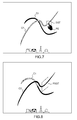
figure 5 , the user wants to use the plane of the first curve C1, thus he starts with a long hold on the plane-shaped graphical tool PSGT. A long hold can be described as a contact of the pointing element PE within an activation zone associated to the plane-shaped graphical tool PSGT maintained without being released, for a period of time equal to or in excess of a threshold time limit. - Thus, when such a long hold is performed, as illustrated on
figure 6 , the plane-shaped graphical tool PSGT is transformed in a selection graphical tool SGT, represented, in the present example by a smaller rectangle. For example, the selection graphical tool SGT can be partly transparent. - On
figure 7 , without releasing the pointing element PE, the user moves the selection graphical tool SGT around, and for example, a pre-highlight, or a color change, or any other visual indication can indicates which curve would be selected, in the present example the curve C1. - Thus, when the pointing element PE is released, as represented on
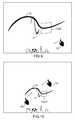
figure 8 , the C1 curve's plane is retrieved, and the plane-shaped graphical tool PSGT is positioned accordingly. The extraction of the working plane of the object at the current position of the pointing element and the definition of said plane as the current working plane represented by the plane-shaped graphical tool (PSGT) can be made using the plane normal to the object at the current position of the pointing element. - Alternatively, it is possible to extract the plane attribute on the object.
- Then, as illustrated on
figure 9 , the user can navigate in the three dimensional scene by manipulating outside the manipulator. Here the user rotates the viewpoint using the pointing element, in this case the finger of the user. - As illustrated on
figure 10 , a zoom in or zoom out can be made, for example using a pinch gesture on a multi-touch screen with two fingers corresponding to two pointing elements PE. - On
figure 11 , is represented, an embodiment of the method according to an aspect of the invention. - The user starts manipulating, in a step 101, a three-dimensional modeled object in a three-dimensional scene.
- A
test 102 is performed to check if the user starts with a hold gesture on the plane-shaped graphical tool PSGT with a pointing element PE. - If the
test 102 is positive, the followingmanipulation 103 is used for selection, and atest 104 is performed to test if an object has been selected. - If the
test 104 is positive, a part of the object is selected 105 when releasing the pointing element PE, and then a working plane is extracted from the selected part of the object. - Then, when the
extraction 106 is ended, the manipulation is ended 108, as if thestep 104 is negative. - If the
test 102 is negative, the manipulation takes place normally 107 and ends 108. -
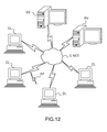
Figure 12 illustrates a computer network or similar digital processing environment in which the present invention may be implemented. - Client computer(s)/devices CL and server computer(s) SV provide processing, storage, and input/output devices executing application programs and the like. Client computer(s)/devices CL can also be linked through communications network CNET to other computing devices, including other client devices/processes CL and server computer(s) SV. Communications network 70 can be part of a remote access network, a global network (e.g., the Internet), a worldwide collection of computers, Local area or Wide area networks, and gateways that currently use respective protocols (TCP/IP, Bluetooth, etc.) to communicate with one another. Other electronic device/computer network architectures are suitable.
-
Figure 13 is a diagram of the internal structure of a computer (e.g., client processor/device CL or server computers SV) in the computer system offigure 12 . Each computer CL, SV contains system bus SB, where a bus is a set of hardware lines used for data transfer among the components of a computer or processing system. Bus SB is essentially a shared conduit that connects different elements of a computer system (e.g., processor, disk storage, memory, input/output ports, network ports, etc...) that enables the transfer of information between the elements. - Attached to system bus SB is I/O device interface DI for connecting various input and output devices (e.g., keyboard, mouse, displays, printers, speakers, etc.) to the computer CL, SV. Network interface NI allows the computer to connect to various other devices attached to a network (e.g., network CNET of
figure 12 ). - Memory MEM provides volatile storage for computer software instructions SI and data CPP used to implement an embodiment of the present invention (e.g., a first path builder PB, means CM for computing a second path, an updater UD implementing the method discussed in
Figs 1 to 11 , and supporting code detailed above). - Disk storage DS provides non-volatile storage for computer software instructions SI and data DAT used to implement an embodiment of the present invention. Central processor unit CPU is also attached to system bus SB and provides for the execution of computer instructions.
- In one embodiment, the processor routines SI and data DAT are a computer program product (generally referenced CPP), including a computer readable medium (e.g., a removable storage medium such as one or more DVD-ROM's, CD-ROM's, diskettes, tapes, etc...) that provides at least a portion of the software instructions for the invention system. Computer program product CPP can be installed by any suitable software installation procedure, as is well known in the art.
- In another embodiment, at least a portion of the software instructions may also be downloaded over a cable, communication and/or wireless connection. In other embodiments, the invention programs are a computer program propagated signal product SP embodied on a propagated signal on a propagation medium (e.g., a radio wave, an infrared wave, a laser wave, a sound wave, or an electrical wave propagated over a global network such as the Internet, or other network(s)). Such carrier medium or signals provide at least a portion of the software instructions for the present invention routines/program CPP.
- In alternate embodiments, the propagated signal is an analog carrier wave or digital signal carried on the propagated medium. For example, the propagated signal may be a digitized signal propagated over a global network (e.g., the Internet), a telecommunications network, or other network.
- In one embodiment, the propagated signal is a signal that is transmitted over the propagation medium over a period of time, such as the instructions for a software application sent in packets over a network over a period of milliseconds, seconds, minutes, or longer. activated on the screen, and for example by projecting them on the drawing plane
(when the drawing plane is different from the screen plane). Thus, the stroke
corresponds to the user-interacting (S1) in the sense that it is derived from what is
sketched by the user through the user-interacting. Thus, in a sense, the stroke is
sketched by the user through the user-interacting (S1). As a result, the definition of 5
the stroke is entirely life-like, the support virtually corresponding here to the drawing
paper (the paper being virtually orthogonally faced by the designer when the support
is the screen plane). - In another embodiment, the computer readable medium of computer program product CPP is a propagation medium that the computer system CL may receive and read, such as by receiving the propagation medium and identifying a propagated signal embodied in the propagation medium, as described above for computer program propagated signal product.
- Generally speaking, the term "carrier medium" or transient carrier encompasses the foregoing transient signals, propagated signals, propagated medium, storage medium and the like.
- While this invention has been particularly shown and described with references to example embodiments thereof, it will be understood by those skilled in the art that various changes in form and details may be made therein without departing from the scope of the invention encompassed by the appended claims.
Claims (7)
- A computer-implemented method for designing a three-dimensional modeled object comprising the steps of :- providing the three-dimensional modeled object in a three-dimensional scene;- displaying a plane-shaped graphical tool (PSGT) defining a current working plane;- pointing and activating the plane-shaped graphical tool (PSGT) with a pointing element (PE);- without releasing the pointing element (PE), hovering a part of the three-dimensional modeled object;- selecting said part of the three-dimensional modeled object when releasing the pointing element (PE);- extracting a working plane from the selected object at the current position of the pointing element and defining said plane as the current working plane represented by the plane-shaped graphical tool (PSGT); and- performing a designing operation in the current working plane.
- Computer-implemented method according to claim 1, wherein the plane-shaped graphical tool (PSGT) is transformed in a selection graphical tool (SGT) when activated, until the release of the pointing element (PE), with a different representation.
- Computer-implemented method according to claim 1 or 2, wherein the selection graphical tool (SGT) is partially transparent.
- Computer-implemented method according to claim 1 to 3, wherein the step of extracting a working plane of the part and defining said plane as the current working plane represented by the plane-shaped graphical tool (PSGT) uses the plane normal to the object at the current position of the pointing element.
- A computer-readable medium having computer-executable instructions to cause the computer system to perform the method for designing a three-dimensional modeled object of anyone of claims 1 to 4.
- A computer program product, stored on a computer readable medium, comprising code means for causing the system to take the steps of the method for designing a three-dimensional modeled object of anyone of claims 1 to 4.
- An apparatus for designing a three-dimensional modeled object comprising means for implementing the steps of the method for designing a three-dimensional modeled object of anyone of claims 1 to 4.
Priority Applications (6)
| Application Number | Priority Date | Filing Date | Title |
|---|---|---|---|
| EP13306895.7A EP2889738B1 (en) | 2013-12-30 | 2013-12-30 | Computer-implemented method for designing a three-dimensional modeled object |
| US14/571,181 US10496237B2 (en) | 2013-12-30 | 2014-12-15 | Computer-implemented method for designing a three-dimensional modeled object |
| JP2014261106A JP6401046B2 (en) | 2013-12-30 | 2014-12-24 | Computer-implemented method for designing 3D modeled objects |
| CN201410821635.8A CN104750905B (en) | 2013-12-30 | 2014-12-25 | Computer-implemented method for designing a three-dimensional modeled object |
| KR1020140192349A KR20150079453A (en) | 2013-12-30 | 2014-12-29 | A computer-implemented method for designing a three-dimensional modeled object |
| CA2876444A CA2876444A1 (en) | 2013-12-30 | 2014-12-30 | A computer-implemented method for designing a three-dimensional modeled object |
Applications Claiming Priority (1)
| Application Number | Priority Date | Filing Date | Title |
|---|---|---|---|
| EP13306895.7A EP2889738B1 (en) | 2013-12-30 | 2013-12-30 | Computer-implemented method for designing a three-dimensional modeled object |
Publications (2)
| Publication Number | Publication Date |
|---|---|
| EP2889738A1 true EP2889738A1 (en) | 2015-07-01 |
| EP2889738B1 EP2889738B1 (en) | 2020-08-12 |
Family
ID=50002443
Family Applications (1)
| Application Number | Title | Priority Date | Filing Date |
|---|---|---|---|
| EP13306895.7A Active EP2889738B1 (en) | 2013-12-30 | 2013-12-30 | Computer-implemented method for designing a three-dimensional modeled object |
Country Status (6)
| Country | Link |
|---|---|
| US (1) | US10496237B2 (en) |
| EP (1) | EP2889738B1 (en) |
| JP (1) | JP6401046B2 (en) |
| KR (1) | KR20150079453A (en) |
| CN (1) | CN104750905B (en) |
| CA (1) | CA2876444A1 (en) |
Cited By (1)
| Publication number | Priority date | Publication date | Assignee | Title |
|---|---|---|---|---|
| EP3506214A1 (en) * | 2017-12-28 | 2019-07-03 | Dassault Systèmes | Method for defining drawing planes for the design of a 3d object |
Families Citing this family (1)
| Publication number | Priority date | Publication date | Assignee | Title |
|---|---|---|---|---|
| JP6499028B2 (en) | 2015-06-25 | 2019-04-10 | 株式会社シマノ | Bicycle shift control device for controlling transmission and bicycle shift control system including transmission |
Citations (5)
| Publication number | Priority date | Publication date | Assignee | Title |
|---|---|---|---|---|
| US5588098A (en) * | 1991-11-22 | 1996-12-24 | Apple Computer, Inc. | Method and apparatus for direct manipulation of 3-D objects on computer displays |
| EP1059581A2 (en) * | 1999-06-10 | 2000-12-13 | Dassault Systèmes | Knowledge-based polymorph undockable toolbar |
| US6426745B1 (en) * | 1997-04-28 | 2002-07-30 | Computer Associates Think, Inc. | Manipulating graphic objects in 3D scenes |
| US20120226983A1 (en) * | 2011-03-01 | 2012-09-06 | Lucasfilm Entertainment Company Ltd. | Copying an Object in an Animation Creation Application |
| US20130181972A1 (en) * | 2012-01-16 | 2013-07-18 | Autodesk, Inc. | Three dimensional contriver tool for modeling with multi-touch devices |
Family Cites Families (16)
| Publication number | Priority date | Publication date | Assignee | Title |
|---|---|---|---|---|
| JPS6015711A (en) * | 1983-07-07 | 1985-01-26 | Fanuc Ltd | Forming method of curved surface |
| JPH05289726A (en) * | 1992-04-14 | 1993-11-05 | Fanuc Ltd | Sectional shape production system for generation of free curved surface |
| JP3599360B2 (en) * | 1993-08-25 | 2004-12-08 | キヤノン株式会社 | Shape modeling device and shape modeling method |
| JPH07249052A (en) * | 1994-03-08 | 1995-09-26 | Mitsubishi Electric Corp | Three-dimensional mechanism conceptual chart plotting device |
| US6308144B1 (en) * | 1996-09-26 | 2001-10-23 | Computervision Corporation | Method and apparatus for providing three-dimensional model associativity |
| US6822662B1 (en) * | 1999-03-31 | 2004-11-23 | International Business Machines Corporation | User selected display of two-dimensional window in three dimensions on a computer screen |
| US6762778B1 (en) * | 1999-06-10 | 2004-07-13 | Dassault Systemes | Three dimensional graphical manipulator |
| US20030001906A1 (en) * | 2001-06-28 | 2003-01-02 | Light John J. | Moving an object on a drag plane in a virtual three-dimensional space |
| JP4856183B2 (en) * | 2006-07-25 | 2012-01-18 | 富士通株式会社 | Operability verification apparatus, operability verification method, and operability verification program |
| US20080088621A1 (en) * | 2006-10-11 | 2008-04-17 | Jean-Jacques Grimaud | Follower method for three dimensional images |
| US20120001922A1 (en) * | 2009-01-26 | 2012-01-05 | Escher Marc | System and method for creating and sharing personalized fonts on a client/server architecture |
| EP2415025B1 (en) * | 2009-03-31 | 2017-07-26 | Vorum Research Corporation | Method and apparatus for applying a rotational transform to a portion of a three-dimensional representation of an appliance for a living body |
| US10019440B2 (en) * | 2011-05-27 | 2018-07-10 | Adobe Systems Incorporated | Methods and apparatus for three-dimensional (3D) sketching |
| JP2013167481A (en) * | 2012-02-14 | 2013-08-29 | Olympus Corp | Image processor and program |
| US9075933B2 (en) * | 2012-10-11 | 2015-07-07 | Adobe Systems Incorporated | 3D transformation of objects using 2D controls projected in 3D space and contextual face selections of a three dimensional bounding box |
| US9330504B2 (en) * | 2013-04-30 | 2016-05-03 | Hover Inc. | 3D building model construction tools |
-
2013
- 2013-12-30 EP EP13306895.7A patent/EP2889738B1/en active Active
-
2014
- 2014-12-15 US US14/571,181 patent/US10496237B2/en active Active
- 2014-12-24 JP JP2014261106A patent/JP6401046B2/en active Active
- 2014-12-25 CN CN201410821635.8A patent/CN104750905B/en active Active
- 2014-12-29 KR KR1020140192349A patent/KR20150079453A/en not_active Application Discontinuation
- 2014-12-30 CA CA2876444A patent/CA2876444A1/en not_active Abandoned
Patent Citations (5)
| Publication number | Priority date | Publication date | Assignee | Title |
|---|---|---|---|---|
| US5588098A (en) * | 1991-11-22 | 1996-12-24 | Apple Computer, Inc. | Method and apparatus for direct manipulation of 3-D objects on computer displays |
| US6426745B1 (en) * | 1997-04-28 | 2002-07-30 | Computer Associates Think, Inc. | Manipulating graphic objects in 3D scenes |
| EP1059581A2 (en) * | 1999-06-10 | 2000-12-13 | Dassault Systèmes | Knowledge-based polymorph undockable toolbar |
| US20120226983A1 (en) * | 2011-03-01 | 2012-09-06 | Lucasfilm Entertainment Company Ltd. | Copying an Object in an Animation Creation Application |
| US20130181972A1 (en) * | 2012-01-16 | 2013-07-18 | Autodesk, Inc. | Three dimensional contriver tool for modeling with multi-touch devices |
Non-Patent Citations (2)
| Title |
|---|
| OSCAR KIN-CHUNG AU ET AL: "Multitouch Gestures for Constrained Transformation of 3D Objects", COMPUTER GRAPHICS FORUM, vol. 31, no. 2pt3, 20 May 2012 (2012-05-20), pages 651 - 660, XP055120422, ISSN: 0167-7055, DOI: 10.1111/j.1467-8659.2012.03044.x * |
| YUNA KANG ET AL: "Feature-based 3D CAD Modeling on Smart Device Using Multi-touch Gesture", INTERNATIONAL JOURNAL OF CAD/CAM, 7 December 2012 (2012-12-07), pages 49 - 62, XP055121354, Retrieved from the Internet <URL:http://ijcc.org/ojs/index.php/ijcc/article/viewFile/244/153> [retrieved on 20140603] * |
Cited By (2)
| Publication number | Priority date | Publication date | Assignee | Title |
|---|---|---|---|---|
| EP3506214A1 (en) * | 2017-12-28 | 2019-07-03 | Dassault Systèmes | Method for defining drawing planes for the design of a 3d object |
| US10769824B2 (en) | 2017-12-28 | 2020-09-08 | Dassault Systemes | Method for defining drawing planes for the design of a 3D object |
Also Published As
| Publication number | Publication date |
|---|---|
| EP2889738B1 (en) | 2020-08-12 |
| US20150186007A1 (en) | 2015-07-02 |
| CN104750905B (en) | 2021-10-15 |
| CA2876444A1 (en) | 2015-06-30 |
| JP2015127963A (en) | 2015-07-09 |
| KR20150079453A (en) | 2015-07-08 |
| CN104750905A (en) | 2015-07-01 |
| JP6401046B2 (en) | 2018-10-03 |
| US10496237B2 (en) | 2019-12-03 |
Similar Documents
| Publication | Publication Date | Title |
|---|---|---|
| KR101597383B1 (en) | Multi-touch object inertia simulation | |
| JP5807686B2 (en) | Image processing apparatus, image processing method, and program | |
| US20120113223A1 (en) | User Interaction in Augmented Reality | |
| EP2333651A1 (en) | Method and system for duplicating an object using a touch-sensitive display | |
| EP2482176A2 (en) | Multi-input gesture control for a display screen | |
| US20140129985A1 (en) | Touch based selection of graphical elements | |
| JP2019087284A (en) | Interaction method for user interfaces | |
| Medeiros et al. | A tablet-based 3d interaction tool for virtual engineering environments | |
| CN104508599A (en) | Element selection device, element selection method, and program | |
| Alshaal et al. | Enhancing virtual reality systems with smart wearable devices | |
| KR102021851B1 (en) | Method for processing interaction between object and user of virtual reality environment | |
| US10496237B2 (en) | Computer-implemented method for designing a three-dimensional modeled object | |
| US10775981B2 (en) | Device with a touch-sensitive display comprising a mechanism to copy and manipulate modeled objects | |
| US9472024B2 (en) | Computer-implemented method for designing a three-dimensional modeled object | |
| US9007398B1 (en) | Rotated rectangle drawing | |
| CN104731470B (en) | Method, apparatus, and medium for configuring a tool using a pointing element | |
| CN102622178A (en) | Touch screen electronic equipment-based method for warping plane image | |
| Aseeri et al. | Poster: Virtual reality interaction using mobile devices | |
| US11029828B2 (en) | Object connection breaking system and method | |
| CN104063140A (en) | Object selection method and electronic equipment | |
| WO2013109244A1 (en) | Three dimensional contriver tool for modeling with multi-touch devices |
Legal Events
| Date | Code | Title | Description |
|---|---|---|---|
| PUAI | Public reference made under article 153(3) epc to a published international application that has entered the european phase |
Free format text: ORIGINAL CODE: 0009012 |
|
| 17P | Request for examination filed |
Effective date: 20131230 |
|
| AK | Designated contracting states |
Kind code of ref document: A1 Designated state(s): AL AT BE BG CH CY CZ DE DK EE ES FI FR GB GR HR HU IE IS IT LI LT LU LV MC MK MT NL NO PL PT RO RS SE SI SK SM TR |
|
| AX | Request for extension of the european patent |
Extension state: BA ME |
|
| R17P | Request for examination filed (corrected) |
Effective date: 20151123 |
|
| RBV | Designated contracting states (corrected) |
Designated state(s): AL AT BE BG CH CY CZ DE DK EE ES FI FR GB GR HR HU IE IS IT LI LT LU LV MC MK MT NL NO PL PT RO RS SE SI SK SM TR |
|
| STAA | Information on the status of an ep patent application or granted ep patent |
Free format text: STATUS: EXAMINATION IS IN PROGRESS |
|
| 17Q | First examination report despatched |
Effective date: 20180921 |
|
| REG | Reference to a national code |
Ref country code: DE Ref legal event code: R079 Ref document number: 602013071533 Country of ref document: DE Free format text: PREVIOUS MAIN CLASS: G06F0003048100 Ipc: G06T0019000000 |
|
| GRAP | Despatch of communication of intention to grant a patent |
Free format text: ORIGINAL CODE: EPIDOSNIGR1 |
|
| STAA | Information on the status of an ep patent application or granted ep patent |
Free format text: STATUS: GRANT OF PATENT IS INTENDED |
|
| RIC1 | Information provided on ipc code assigned before grant |
Ipc: G06F 3/0481 20130101ALI20200311BHEP Ipc: G06F 3/0484 20130101ALI20200311BHEP Ipc: G06T 19/00 20110101AFI20200311BHEP Ipc: G06F 3/0488 20130101ALI20200311BHEP |
|
| INTG | Intention to grant announced |
Effective date: 20200409 |
|
| GRAS | Grant fee paid |
Free format text: ORIGINAL CODE: EPIDOSNIGR3 |
|
| GRAA | (expected) grant |
Free format text: ORIGINAL CODE: 0009210 |
|
| STAA | Information on the status of an ep patent application or granted ep patent |
Free format text: STATUS: THE PATENT HAS BEEN GRANTED |
|
| AK | Designated contracting states |
Kind code of ref document: B1 Designated state(s): AL AT BE BG CH CY CZ DE DK EE ES FI FR GB GR HR HU IE IS IT LI LT LU LV MC MK MT NL NO PL PT RO RS SE SI SK SM TR |
|
| REG | Reference to a national code |
Ref country code: CH Ref legal event code: EP |
|
| REG | Reference to a national code |
Ref country code: DE Ref legal event code: R096 Ref document number: 602013071533 Country of ref document: DE |
|
| REG | Reference to a national code |
Ref country code: IE Ref legal event code: FG4D |
|
| REG | Reference to a national code |
Ref country code: AT Ref legal event code: REF Ref document number: 1302299 Country of ref document: AT Kind code of ref document: T Effective date: 20200915 |
|
| REG | Reference to a national code |
Ref country code: SE Ref legal event code: TRGR |
|
| REG | Reference to a national code |
Ref country code: LT Ref legal event code: MG4D |
|
| REG | Reference to a national code |
Ref country code: NL Ref legal event code: MP Effective date: 20200812 |
|
| PG25 | Lapsed in a contracting state [announced via postgrant information from national office to epo] |
Ref country code: LT Free format text: LAPSE BECAUSE OF FAILURE TO SUBMIT A TRANSLATION OF THE DESCRIPTION OR TO PAY THE FEE WITHIN THE PRESCRIBED TIME-LIMIT Effective date: 20200812 Ref country code: ES Free format text: LAPSE BECAUSE OF FAILURE TO SUBMIT A TRANSLATION OF THE DESCRIPTION OR TO PAY THE FEE WITHIN THE PRESCRIBED TIME-LIMIT Effective date: 20200812 Ref country code: BG Free format text: LAPSE BECAUSE OF FAILURE TO SUBMIT A TRANSLATION OF THE DESCRIPTION OR TO PAY THE FEE WITHIN THE PRESCRIBED TIME-LIMIT Effective date: 20201112 Ref country code: HR Free format text: LAPSE BECAUSE OF FAILURE TO SUBMIT A TRANSLATION OF THE DESCRIPTION OR TO PAY THE FEE WITHIN THE PRESCRIBED TIME-LIMIT Effective date: 20200812 Ref country code: FI Free format text: LAPSE BECAUSE OF FAILURE TO SUBMIT A TRANSLATION OF THE DESCRIPTION OR TO PAY THE FEE WITHIN THE PRESCRIBED TIME-LIMIT Effective date: 20200812 Ref country code: GR Free format text: LAPSE BECAUSE OF FAILURE TO SUBMIT A TRANSLATION OF THE DESCRIPTION OR TO PAY THE FEE WITHIN THE PRESCRIBED TIME-LIMIT Effective date: 20201113 Ref country code: NO Free format text: LAPSE BECAUSE OF FAILURE TO SUBMIT A TRANSLATION OF THE DESCRIPTION OR TO PAY THE FEE WITHIN THE PRESCRIBED TIME-LIMIT Effective date: 20201112 |
|
| REG | Reference to a national code |
Ref country code: AT Ref legal event code: MK05 Ref document number: 1302299 Country of ref document: AT Kind code of ref document: T Effective date: 20200812 |
|
| PG25 | Lapsed in a contracting state [announced via postgrant information from national office to epo] |
Ref country code: IS Free format text: LAPSE BECAUSE OF FAILURE TO SUBMIT A TRANSLATION OF THE DESCRIPTION OR TO PAY THE FEE WITHIN THE PRESCRIBED TIME-LIMIT Effective date: 20201212 Ref country code: RS Free format text: LAPSE BECAUSE OF FAILURE TO SUBMIT A TRANSLATION OF THE DESCRIPTION OR TO PAY THE FEE WITHIN THE PRESCRIBED TIME-LIMIT Effective date: 20200812 Ref country code: NL Free format text: LAPSE BECAUSE OF FAILURE TO SUBMIT A TRANSLATION OF THE DESCRIPTION OR TO PAY THE FEE WITHIN THE PRESCRIBED TIME-LIMIT Effective date: 20200812 Ref country code: PL Free format text: LAPSE BECAUSE OF FAILURE TO SUBMIT A TRANSLATION OF THE DESCRIPTION OR TO PAY THE FEE WITHIN THE PRESCRIBED TIME-LIMIT Effective date: 20200812 Ref country code: LV Free format text: LAPSE BECAUSE OF FAILURE TO SUBMIT A TRANSLATION OF THE DESCRIPTION OR TO PAY THE FEE WITHIN THE PRESCRIBED TIME-LIMIT Effective date: 20200812 |
|
| PG25 | Lapsed in a contracting state [announced via postgrant information from national office to epo] |
Ref country code: SM Free format text: LAPSE BECAUSE OF FAILURE TO SUBMIT A TRANSLATION OF THE DESCRIPTION OR TO PAY THE FEE WITHIN THE PRESCRIBED TIME-LIMIT Effective date: 20200812 Ref country code: RO Free format text: LAPSE BECAUSE OF FAILURE TO SUBMIT A TRANSLATION OF THE DESCRIPTION OR TO PAY THE FEE WITHIN THE PRESCRIBED TIME-LIMIT Effective date: 20200812 Ref country code: CZ Free format text: LAPSE BECAUSE OF FAILURE TO SUBMIT A TRANSLATION OF THE DESCRIPTION OR TO PAY THE FEE WITHIN THE PRESCRIBED TIME-LIMIT Effective date: 20200812 Ref country code: DK Free format text: LAPSE BECAUSE OF FAILURE TO SUBMIT A TRANSLATION OF THE DESCRIPTION OR TO PAY THE FEE WITHIN THE PRESCRIBED TIME-LIMIT Effective date: 20200812 Ref country code: EE Free format text: LAPSE BECAUSE OF FAILURE TO SUBMIT A TRANSLATION OF THE DESCRIPTION OR TO PAY THE FEE WITHIN THE PRESCRIBED TIME-LIMIT Effective date: 20200812 |
|
| REG | Reference to a national code |
Ref country code: DE Ref legal event code: R097 Ref document number: 602013071533 Country of ref document: DE |
|
| PG25 | Lapsed in a contracting state [announced via postgrant information from national office to epo] |
Ref country code: AT Free format text: LAPSE BECAUSE OF FAILURE TO SUBMIT A TRANSLATION OF THE DESCRIPTION OR TO PAY THE FEE WITHIN THE PRESCRIBED TIME-LIMIT Effective date: 20200812 Ref country code: AL Free format text: LAPSE BECAUSE OF FAILURE TO SUBMIT A TRANSLATION OF THE DESCRIPTION OR TO PAY THE FEE WITHIN THE PRESCRIBED TIME-LIMIT Effective date: 20200812 |
|
| PLBE | No opposition filed within time limit |
Free format text: ORIGINAL CODE: 0009261 |
|
| STAA | Information on the status of an ep patent application or granted ep patent |
Free format text: STATUS: NO OPPOSITION FILED WITHIN TIME LIMIT |
|
| PG25 | Lapsed in a contracting state [announced via postgrant information from national office to epo] |
Ref country code: SK Free format text: LAPSE BECAUSE OF FAILURE TO SUBMIT A TRANSLATION OF THE DESCRIPTION OR TO PAY THE FEE WITHIN THE PRESCRIBED TIME-LIMIT Effective date: 20200812 |
|
| 26N | No opposition filed |
Effective date: 20210514 |
|
| REG | Reference to a national code |
Ref country code: CH Ref legal event code: PL |
|
| PG25 | Lapsed in a contracting state [announced via postgrant information from national office to epo] |
Ref country code: SI Free format text: LAPSE BECAUSE OF FAILURE TO SUBMIT A TRANSLATION OF THE DESCRIPTION OR TO PAY THE FEE WITHIN THE PRESCRIBED TIME-LIMIT Effective date: 20200812 Ref country code: MC Free format text: LAPSE BECAUSE OF FAILURE TO SUBMIT A TRANSLATION OF THE DESCRIPTION OR TO PAY THE FEE WITHIN THE PRESCRIBED TIME-LIMIT Effective date: 20200812 |
|
| REG | Reference to a national code |
Ref country code: BE Ref legal event code: MM Effective date: 20201231 |
|
| PG25 | Lapsed in a contracting state [announced via postgrant information from national office to epo] |
Ref country code: IE Free format text: LAPSE BECAUSE OF NON-PAYMENT OF DUE FEES Effective date: 20201230 Ref country code: LU Free format text: LAPSE BECAUSE OF NON-PAYMENT OF DUE FEES Effective date: 20201230 |
|
| PG25 | Lapsed in a contracting state [announced via postgrant information from national office to epo] |
Ref country code: LI Free format text: LAPSE BECAUSE OF NON-PAYMENT OF DUE FEES Effective date: 20201231 Ref country code: CH Free format text: LAPSE BECAUSE OF NON-PAYMENT OF DUE FEES Effective date: 20201231 |
|
| PG25 | Lapsed in a contracting state [announced via postgrant information from national office to epo] |
Ref country code: TR Free format text: LAPSE BECAUSE OF FAILURE TO SUBMIT A TRANSLATION OF THE DESCRIPTION OR TO PAY THE FEE WITHIN THE PRESCRIBED TIME-LIMIT Effective date: 20200812 Ref country code: MT Free format text: LAPSE BECAUSE OF FAILURE TO SUBMIT A TRANSLATION OF THE DESCRIPTION OR TO PAY THE FEE WITHIN THE PRESCRIBED TIME-LIMIT Effective date: 20200812 Ref country code: CY Free format text: LAPSE BECAUSE OF FAILURE TO SUBMIT A TRANSLATION OF THE DESCRIPTION OR TO PAY THE FEE WITHIN THE PRESCRIBED TIME-LIMIT Effective date: 20200812 |
|
| PG25 | Lapsed in a contracting state [announced via postgrant information from national office to epo] |
Ref country code: MK Free format text: LAPSE BECAUSE OF FAILURE TO SUBMIT A TRANSLATION OF THE DESCRIPTION OR TO PAY THE FEE WITHIN THE PRESCRIBED TIME-LIMIT Effective date: 20200812 |
|
| PG25 | Lapsed in a contracting state [announced via postgrant information from national office to epo] |
Ref country code: PT Free format text: LAPSE BECAUSE OF FAILURE TO SUBMIT A TRANSLATION OF THE DESCRIPTION OR TO PAY THE FEE WITHIN THE PRESCRIBED TIME-LIMIT Effective date: 20200812 Ref country code: BE Free format text: LAPSE BECAUSE OF NON-PAYMENT OF DUE FEES Effective date: 20201231 |
|
| P01 | Opt-out of the competence of the unified patent court (upc) registered |
Effective date: 20230529 |
|
| PGFP | Annual fee paid to national office [announced via postgrant information from national office to epo] |
Ref country code: GB Payment date: 20231116 Year of fee payment: 11 |
|
| PGFP | Annual fee paid to national office [announced via postgrant information from national office to epo] |
Ref country code: SE Payment date: 20231127 Year of fee payment: 11 Ref country code: IT Payment date: 20231128 Year of fee payment: 11 Ref country code: FR Payment date: 20231122 Year of fee payment: 11 Ref country code: DE Payment date: 20231114 Year of fee payment: 11 |