EP2849105A1 - Method for planning transplantation of hair follicular units - Google Patents
Method for planning transplantation of hair follicular units Download PDFInfo
- Publication number
- EP2849105A1 EP2849105A1 EP14184395.3A EP14184395A EP2849105A1 EP 2849105 A1 EP2849105 A1 EP 2849105A1 EP 14184395 A EP14184395 A EP 14184395A EP 2849105 A1 EP2849105 A1 EP 2849105A1
- Authority
- EP
- European Patent Office
- Prior art keywords
- hair
- body surface
- proposed
- follicular
- follicular unit
- Prior art date
- Legal status (The legal status is an assumption and is not a legal conclusion. Google has not performed a legal analysis and makes no representation as to the accuracy of the status listed.)
- Granted
Links
- 230000003325 follicular Effects 0.000 title claims abstract description 158
- 210000004209 hair Anatomy 0.000 title claims abstract description 158
- 238000000034 method Methods 0.000 title claims abstract description 104
- 238000002054 transplantation Methods 0.000 title claims abstract description 31
- 238000002513 implantation Methods 0.000 claims abstract description 67
- 210000003780 hair follicle Anatomy 0.000 claims abstract description 62
- 239000007943 implant Substances 0.000 claims description 19
- 238000010276 construction Methods 0.000 claims description 17
- 230000008569 process Effects 0.000 claims description 8
- 238000012545 processing Methods 0.000 claims description 8
- 238000009877 rendering Methods 0.000 claims description 7
- 238000003860 storage Methods 0.000 claims description 3
- 239000002537 cosmetic Substances 0.000 abstract description 8
- 210000004761 scalp Anatomy 0.000 description 24
- 238000003306 harvesting Methods 0.000 description 23
- 210000003128 head Anatomy 0.000 description 14
- 238000013461 design Methods 0.000 description 11
- 239000000203 mixture Substances 0.000 description 9
- 238000009472 formulation Methods 0.000 description 5
- 239000003550 marker Substances 0.000 description 3
- 238000012986 modification Methods 0.000 description 3
- 230000004048 modification Effects 0.000 description 3
- 230000008901 benefit Effects 0.000 description 2
- 230000008859 change Effects 0.000 description 2
- 239000013256 coordination polymer Substances 0.000 description 2
- 230000003362 replicative effect Effects 0.000 description 2
- 201000004384 Alopecia Diseases 0.000 description 1
- 210000003484 anatomy Anatomy 0.000 description 1
- 206010068168 androgenetic alopecia Diseases 0.000 description 1
- 230000006399 behavior Effects 0.000 description 1
- 238000011960 computer-aided design Methods 0.000 description 1
- 210000005069 ears Anatomy 0.000 description 1
- 238000005516 engineering process Methods 0.000 description 1
- 230000006870 function Effects 0.000 description 1
- 238000003709 image segmentation Methods 0.000 description 1
- 238000003384 imaging method Methods 0.000 description 1
- 206010033675 panniculitis Diseases 0.000 description 1
- 210000004304 subcutaneous tissue Anatomy 0.000 description 1
- 239000013598 vector Substances 0.000 description 1
Images


Classifications
-
- G—PHYSICS
- G06—COMPUTING; CALCULATING OR COUNTING
- G06T—IMAGE DATA PROCESSING OR GENERATION, IN GENERAL
- G06T17/00—Three dimensional [3D] modelling, e.g. data description of 3D objects
-
- G—PHYSICS
- G16—INFORMATION AND COMMUNICATION TECHNOLOGY [ICT] SPECIALLY ADAPTED FOR SPECIFIC APPLICATION FIELDS
- G16H—HEALTHCARE INFORMATICS, i.e. INFORMATION AND COMMUNICATION TECHNOLOGY [ICT] SPECIALLY ADAPTED FOR THE HANDLING OR PROCESSING OF MEDICAL OR HEALTHCARE DATA
- G16H50/00—ICT specially adapted for medical diagnosis, medical simulation or medical data mining; ICT specially adapted for detecting, monitoring or modelling epidemics or pandemics
- G16H50/50—ICT specially adapted for medical diagnosis, medical simulation or medical data mining; ICT specially adapted for detecting, monitoring or modelling epidemics or pandemics for simulation or modelling of medical disorders
-
- G—PHYSICS
- G16—INFORMATION AND COMMUNICATION TECHNOLOGY [ICT] SPECIALLY ADAPTED FOR SPECIFIC APPLICATION FIELDS
- G16Z—INFORMATION AND COMMUNICATION TECHNOLOGY [ICT] SPECIALLY ADAPTED FOR SPECIFIC APPLICATION FIELDS, NOT OTHERWISE PROVIDED FOR
- G16Z99/00—Subject matter not provided for in other main groups of this subclass
-
- A—HUMAN NECESSITIES
- A61—MEDICAL OR VETERINARY SCIENCE; HYGIENE
- A61B—DIAGNOSIS; SURGERY; IDENTIFICATION
- A61B17/00—Surgical instruments, devices or methods, e.g. tourniquets
- A61B2017/00743—Type of operation; Specification of treatment sites
- A61B2017/00747—Dermatology
- A61B2017/00752—Hair removal or transplantation
-
- A—HUMAN NECESSITIES
- A61—MEDICAL OR VETERINARY SCIENCE; HYGIENE
- A61B—DIAGNOSIS; SURGERY; IDENTIFICATION
- A61B34/00—Computer-aided surgery; Manipulators or robots specially adapted for use in surgery
- A61B34/10—Computer-aided planning, simulation or modelling of surgical operations
- A61B2034/101—Computer-aided simulation of surgical operations
- A61B2034/102—Modelling of surgical devices, implants or prosthesis
- A61B2034/104—Modelling the effect of the tool, e.g. the effect of an implanted prosthesis or for predicting the effect of ablation or burring
-
- A—HUMAN NECESSITIES
- A61—MEDICAL OR VETERINARY SCIENCE; HYGIENE
- A61B—DIAGNOSIS; SURGERY; IDENTIFICATION
- A61B34/00—Computer-aided surgery; Manipulators or robots specially adapted for use in surgery
- A61B34/10—Computer-aided planning, simulation or modelling of surgical operations
- A61B2034/101—Computer-aided simulation of surgical operations
- A61B2034/105—Modelling of the patient, e.g. for ligaments or bones
-
- A—HUMAN NECESSITIES
- A61—MEDICAL OR VETERINARY SCIENCE; HYGIENE
- A61B—DIAGNOSIS; SURGERY; IDENTIFICATION
- A61B34/00—Computer-aided surgery; Manipulators or robots specially adapted for use in surgery
- A61B34/25—User interfaces for surgical systems
-
- A—HUMAN NECESSITIES
- A61—MEDICAL OR VETERINARY SCIENCE; HYGIENE
- A61F—FILTERS IMPLANTABLE INTO BLOOD VESSELS; PROSTHESES; DEVICES PROVIDING PATENCY TO, OR PREVENTING COLLAPSING OF, TUBULAR STRUCTURES OF THE BODY, e.g. STENTS; ORTHOPAEDIC, NURSING OR CONTRACEPTIVE DEVICES; FOMENTATION; TREATMENT OR PROTECTION OF EYES OR EARS; BANDAGES, DRESSINGS OR ABSORBENT PADS; FIRST-AID KITS
- A61F2/00—Filters implantable into blood vessels; Prostheses, i.e. artificial substitutes or replacements for parts of the body; Appliances for connecting them with the body; Devices providing patency to, or preventing collapsing of, tubular structures of the body, e.g. stents
- A61F2/02—Prostheses implantable into the body
- A61F2/10—Hair or skin implants
Definitions
- This invention relates generally to planning systems and their use for planning transplantation (i.e., harvesting and implantation) of hair follicular units in a body surface, usually a scalp.
- Hair transplantation procedures are well-known, and typically involve harvesting donor hair grafts from the side and back fringe areas ("donor areas") of the person's scalp, and implanting the harvested follicular units in a bald, top area ("recipient area").
- donor areas side and back fringe areas
- recipient area implanting the harvested follicular units in a bald, top area
- the harvested grafts were relatively large (3-5 mm), although more recently, the donor grafts may be single follicular units, which are naturally occurring aggregates of 1-3 (and much less commonly, 4-5) closely spaced hair follicles that are distributed randomly over the surface of the scalp.
- a linear portion of the scalp is removed from a donor area using a scalpel cutting down into the fatty subcutaneous tissue.
- the strip is dissected (under a microscope) into component follicular units, which are then implanted into a recipient area in respective incisions or puncture holes made using a needle. Forceps may be used to grasp and place the individual follicular unit grafts into the needle puncture locations, although other instruments and methods are known for performing this task.
- U.S. Patent No. 6,585,746 discloses a hair transplantation system utilizing a robotic system, including a robotic arm and a hair follicle introducer associated with the robotic arm.
- a video system is used to produce a three-dimensional image of the person's scalp, which is used to plan the scalp locations to receive hair grafts implanted by the follicle introducer under the control of the robotic arm.
- a method of creating a plan for cosmetic transplantation of follicular units in a body surface of a person includes using a three-dimensional model of a body surface to generate on the model proposed follicular unit implantation locations and hair follicle orientations based on certain control points.
- the method may further include acquiring images of the body surface, processing the images to produce a three-dimensional model of the body surface, and displaying a graphic rendering of the body surface model on the monitor.
- a proposed recipient area may be originally identified, subsequently modified, or both, based at least in part on user input.
- the user input may relate to a density or a type (or a mix of type) of follicular units when implanted in an area of the body surface corresponding to the recipient area.
- the location of the recipient area may relate to an appearance or direction of hair follicles growing from follicular units when implanted in an area of the body surface corresponding to the recipient area.
- the proposed method of the present invention allows to plan a frontal hair line, as well as variously located hair patch areas.
- the graphic rendering of the proposed hair follicles locations and orientations may be based, at least in part, on a randomizing of implantation locations of follicular units to be implanted.
- the method may further include identifying user-defined recipient areas, or patches, in which follicular units are to be implanted.
- the method may further include displaying on the body surface model a donor area for harvesting follicular units, wherein the location of the displayed donor area is based, at least in part, on input received through the user interface.
- the location of the displayed donor area may alternatively or additionally be based on one or more of (i) an amount of each of a type of existing follicular unit located in a donor area on the actual body surface corresponding to the displayed donor area, as determined from the acquired images, (ii) a minimum density of follicular units to be left remaining in the donor area after selected harvesting of other follicular units has occurred, and (iii) an approximate amount of each type, color, or both, of existing follicular unit to be implanted in an area of the body surface corresponding to the displayed recipient area.
- the method further comprises identifying locations of follicular units to be harvested from an area on the body surface corresponding to the displayed donor area, identifying locations of implantation sites on the body surface corresponding to the displayed recipient area at which the harvested follicular units are to be implanted, and providing the respective harvest and implantation locations to an automated (e.g., robotic) system for performing the implantation procedure.
- an automated (e.g., robotic) system for performing the implantation procedure.
- a system for planning for the transplantation of follicular units in a body surface of a person includes a user interface comprising a software-controlled processor and an input device.
- the system is configured to display on the monitor a three-dimensional model of the body surface.
- the planning system is further configured to display a proposed recipient area for implanting follicular units on the body surface model, wherein the location of the displayed recipient area may be originally identified, subsequently modified, or both, based at least in part on user input.
- the user input may relate to a density or a type (or a mix of type) of follicular units when implanted in an area of the body surface corresponding to the displayed recipient area.
- the location of the displayed recipient area may relate to an appearance or direction of hair follicles growing from follicular units when implanted in an area of the body surface corresponding to the displayed recipient area.
- the system may also be configured to identify recipient areas, for example, hair line or one or more hair patches, in which follicular units are to be implanted.
- the planning system may be further configured to display on the body surface model a donor area for harvesting follicular units, wherein the location of the displayed donor area is based, at least in part, on input received through the user interface.
- the location of the displayed donor area may alternatively or additionally be based on one or more of (i) an amount of each of a type of existing follicular unit located in a donor area on the actual body surface corresponding to the displayed donor area, as determined from the acquired images, (ii) a minimum density of follicular units to be left remaining in the donor area after selected harvesting of other follicular units has occurred, and (iii) an approximate amount of each type, color, or both, of existing follicular unit to be implanted in an area of the body surface corresponding to the displayed recipient area.
- the planning system identifies locations of follicular units to be harvested from an area on the body surface corresponding to the displayed donor area, and of implantation sites on the body surface corresponding to the displayed recipient area at which the harvested follicular units are to be implanted, and inputs the respective harvest and implantation locations into an automated (e.g., robotic) system for performing the implantation procedure.
- an automated (e.g., robotic) system for performing the implantation procedure.
- a system for creating a plan for cosmetic transplantation of hair follicular units in a body surface includes a user interface including a software-controlled processor and a user input device, wherein the processor is configured to display a three-dimensional model of the body surface, and to generate and display on the model proposed follicular unit implantation locations and hair follicle orientations based on specified control points and orientations at the control points.
- a user may interactively adjust the control point locations and orientations to thereby correspondingly adjust the proposed follicular unit implantation locations and hair follicle orientations.
- a system for creating a plan for cosmetic transplantation of hair follicular units in a body surface includes a user interface including a software-controlled processor and a user input device, wherein the processor is configured to display on a three-dimensional model of the body surface one or more proposed follicular unit recipient areas.
- the user interface is configured to generate and display one or more input menus for receiving user inputs through the user input device for defining and adjusting the one or more proposed recipient areas.
- a method for creating a plan for cosmetic transplantation of hair follicular units in a body surface includes displaying a three-dimensional model of the body surface, generating and displaying on the model proposed follicular unit implantation locations and hair follicle orientations based on specified control points and orientations at the control points, and interactively adjusting the control point locations and orientations to thereby correspondingly adjust the proposed follicular unit implantation locations and hair follicle orientations.
- a system for creating a plan for removing hair follicular units from a body surface includes a user interface including a software-controlled processor and a user input device, wherein the processor is configured to display a three dimensional model of the body surface, and to generate and display a proposed hair removal area on the body surface model.
- the user interface is configured to generate and display one or more input menus for receiving user inputs for adjusting the proposed hair removal area.
- a method for creating a plan for removing hair follicular units from a body surface includes displaying a three dimensional model of a body surface, displaying a proposed hair removal area on the body surface model, and generating and displaying one or more input menus for receiving user inputs for adjusting the proposed hair removal area.
- the aesthetic result of a hair transplantation procedure depends in part on implanting the grafts in natural-looking patterns.
- a computer can efficiently "amplify" a surgeon's skill by "filling in the blanks" among a small fraction of the implant sites for which the surgeon determines graft location and orientation. Achieving a natural-looking hair line is particularly important for a good aesthetic result.
- the surgeon Instead of painstakingly making incisions for all of the near-hairline implant sites, the surgeon indicates a few hairline implant locations and orientations and the computer fills in the rest by interpolating among the designated sites, using the imaging system to identify and avoid existing follicular units.
- Bodduluri et al illustrates an algorithm using control points to design natural looking hairline.
- a curve is designed using control points based on, for example, b-spline cubic polynomials.
- the control points are specified by the operator.
- the orientation of the hair at each of the control points is specified.
- Points along the curve are identified at a given spacing, for instance, by interpolation.
- the locations of the points along the curve may be randomized to make a natural looking hair line.
- the amount of randomization may be user-specified or computer-generated. It is preferable that the follicular unit orientations are not randomized but are interpolated, for example, the same way a cubic spline is generated. Randomization of the location and interpolation of the orientation create more natural looking implants.
- Natural looking randomness is important in both the critical hairline region and in the balance of the recipient sites. This can be achieved using a procedure illustrated in Bodduluri et al, wherein a surface is designed using control points based on, for example, b-spline cubic surfaces. Again, the orientation of the hair at each of the control points is specified. Implant points along the surface are identified at a given spacing. The locations of the points along the surface may be randomized to make a natural looking hair distribution. The amount of randomization may be user-specified or computer-generated. Again, the orientation of the respective follicular units is preferably not randomized, but interpolated the same way a cubic spline surface is generated. Randomization and interpolation schemes are known in the art, and can be adapted for this method.
- Bodduluri et al shows an example of an automatic guidance feature of the robotic system, including the step of planning implant locations and orientations with respect to global landmarks (e.g., existing hairs, tattoos, or other distinguishing features).
- the robot is then moved to register landmarks on the person.
- the register information can be stored in memory for reference.
- the robot can make use of the registered landmarks as reference points for recognizing its position relative to the working surface.
- the robot is moved to each of the implant location and orientation with respect to the global landmarks.
- the global landmarks provide a global reference for global movements.
- the location and orientation are fine-tuned based on the nearby landmarks such as neighboring preexisting hairs or newly implanted hairs.
- the nearby landmarks provide a local reference for local movements.
- the treatment plan is a prescribed plan designed to transplant hair follicles from a first region (harvest region) to a target region (implant region).
- the treatment plan may include one or more parameters, such as a number of hair follicles to be removed/implanted, location of harvest region, location of implant region, a degree of randomness associated with targeted implant locations, spacing between adjacent targeted implant locations, depth of follicle, depth of implant, person identification, geometric profile of harvest region, geometric profile of implant region, marker location(s), and density of targeted implant locations.
- the treatment plan may be inputted using a user interface that includes a monitor and a keyboard.
- the treatment plan may be inputted using a storage device, such as a diskette or a compact disk.
- the treatment plan may be downloaded from a remote server, or from a combination of the forgoing techniques.
- some parameters may be inputted into the computer using a diskette, while other parameters may be inputted using the user interface.
- one or more parameters of the treatment plan may be determined in real time (e.g., during a treatment session).
- the computer After the treatment plan has been input into the computer, the computer then registers the treatment plan with a person. In some embodiments, such may be accomplished by using one or more cameras to identify one or more markers on the person.
- the marker may be a reflector that is secured to the person, an ink mark drawn on the person, or an anatomy of the person.
- the identified marker(s) may be used to determine a position and/or orientation of a target region on the person.
- a system for planning a procedure for the transplantation of follicular units in a body surface (e.g., a scalp) of a person comprises a user interface, including, for example, a software-controlled processor, a monitor, and an input device.
- a user interface including, for example, a software-controlled processor, a monitor, and an input device.
- embodiments of the planning system are preferably (if not exclusively from a practical point of view) software implemented, and may be run on any computer system having the basic components (processor, monitor, input device), so long as such computer system is equipped with sufficient available memory and an appropriate graphic generation and display capability.
- embodiments of the invention may be implemented over the internet, e.g., with a user of such system employing his or her home computer as at least a part of the user interface (monitor and input device) that interacts with a remote server or computer.
- the software that implements and controls the user interface may reside in whole or part on the user's computer or on the remote server/computer, preferably transparent to the user.
- the remote server downloads one or more software modules to the user's computer for temporary or permanent use.
- images are acquired of a body surface of a person, in this case, a front view 20 ( Fig. 1A ) and a side view 22 ( Fig. 1B ) of the person's head (and, in particular, scalp), for which the subject transplantation procedure is being planned.
- the images 20, 22 may be acquired using a hand held digital camera, and input through the user interface of the planning system, in accordance with well-known and available technology for transmitting digital image data. It is not necessary in preferred embodiments to include images of every portion of the person's head, since the modeling software (described below in greater detail) can generate a sufficiently accurate three-dimensional surface model of the head/scalp from just front and side views 20 and 22, respectively.
- the acquired images 20, 22 are then processed to generate a three-dimensional model of the person's head (scalp) using commercially available modeling software.
- FaceGen Modeller 3.1 produced and distributed by Singular Inversions, Inc., Vancouver, Canada (www.facegen.com) is used to generate the three-dimensional model. It will be appreciated that other software programs may alternatively be used.
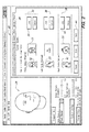
- a monitor screen shot from the user interface taken during use of the FaceGen Modeller program includes a series of pull-down menus 26 related to construction of a model of a human face.
- the menu "PhotoFit" 28 has been selected, resulting in the display of a frontal image 30 (in this case, image 20), a left profile image 36 (an optional input; in this case, not provided) and a right profile image (also optional; in this case, side image 22) of the person.
- the software program displays respective front 32, left profile 33, and right profile 40 images of a model as an example for users of the system.
- the user assigns a series of feature points 52 on the frontal image 20 (designated by reference numeral 48), based on the provided example 50.
- the feature points 52 are placed at distinct physical locations (e.g., corners of the mouth, nose, chin, ears, etc.) of the person's face.
- the image 48 may be rotated using the respective inputs 54.
- the modeling software allows the user to enlarge the frontal image (designated by reference number 58) for accurate placement of the feature points 52. Referring to Figs.
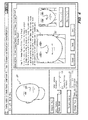
- the process is repeated for assigning feature points to the side profile image(s), in this case to the right profile image 60 in Fig. 5 , and enlarged 64 in Fig. 6 ), with an example model picture 62 provided for illustration. Further information regarding generation of a three-dimensional model based on the acquired front and side images may be ascertained directly from the FaceGen Modeller software.
- the modeling software is configured to generate (by selecting menu option "generate" 64) a three-dimensional model (designated as 24') based on inputs relating to selected characteristics, such as race 66 and other characteristics selected through menus 68 and 70, some objective (e.g., gender, age) and others purely subjective (e.g., attractive).
- further input information is provided to the planning system in addition to generating the body surface model.
- particular features specific to hair follicles e.g., color or coarseness
- Further information may be either user input or determined from the acquired images using image processing, such as geometric shape of the body surface (e.g., person's head), existing hair lines, and a number of each type (i.e., single or multiple follicle) and color (e.g., dark, light, gray, etc.) of follicular unit that are available for harvesting.
- the three dimensional model can alternatively be generated by a number of other methods, for example, using a 3D laser scanner and/or by stiching multiple digital images together.
- the system of embodiments of the present invention will use the three dimensional information in the same way, without regard to how it is generated.
- the modeling software determines and displays on the user interface monitor of the planning system a three-dimensional model 24 of the person's head/scalp.
- the model generated in Figs. 8A and 8B exhibits characteristic male-pattern baldness, including a bald top region 74, and populated side 72 and back 76 regions.
- the planning system will display on the body surface model one or more proposed recipient areas 82 for implanting follicular units.
- An initial location of a proposed front boundary (or "hair line") 78 may be initially identified by the system, or generated based (at least in part) on user input received through the user interface. In either case, it may be modified by the user, as indicated by the arrows 80 e.g., by using a convention click and drag motion of a computer mouse, until the hair line 78 is in a desired location.
- one or more separate regions (or “patches") 85 behind the hair line may also be initially identified by the system, or generated based (at least in part) on user input received through the user interface. As with the hair line 78, the boundaries of the patches 85 may be modified by the user, as indicated by the arrows 84.
- the attending physician or operator can specify where a follicular unit needs to be implanted and at what angle, i.e., its relative location (or "implantation site"), orientation, and depth.
- This specification of the location, orientation and/or depth of a hair follicle to be implanted may be carried out by a treatment planning system.
- the attending operator may use a user interface (e.g., a conventional computer mouse) to specify the implant location and/or position and/or orientation and/or implant depth.
- the operator can point to location on the scalp by placing a temporary fiducial, such as an ink mark or a pointer that can be visualized, identified, and measured by the image processing system.
- a temporary fiducial such as an ink mark or a pointer that can be visualized, identified, and measured by the image processing system.
- orientation can be specified directly on the computer monitor as a combination of two angles, such as rotation about x-axis and a rotation about y-axis (assuming that z-axis is along the needle), or by placing an elongated pointer on the scalp, which the image processing system can visualize and measure the angles.
- input received through the user interface for establishing or modifying the hair line and inner patch boundaries may relate to one or more of a resulting density of the follicular units after they are implanted in the recipient area, a direction of hair follicles that will grow out from the implanted follicular units, and an overall appearance (i.e., hair style) of the hair follicles growing out from the implanted follicular units.
- Other factors such as a geometric shape of the body surface, an ethnicity of the person, an age of the person, a gender of the person, and/or existing hair lines, densities and follicle color(s) on the body surface.
- One or more parameters relating to existing follicular units in an identified donor area of the body surface may also be considered, such as an amount of each type (e.g., single or multiple follicle), color, and a relative coarseness of hair follicles growing from the existing follicular units.
- the available quantity of single follicle follicular units available for harvesting may also play a role in defining the hair line of the recipient area, since the single follicle type of unit is predominantly found in natural front hair lines.
- U.S. patent application serial number 11/467,283, filed August 25, 2006 discloses a method for determining an approximate quantity of each type of existing follicular units that are available for harvesting based on processing images of the potential donor area(s). While such donor area(s) are typically in the back of the scalp, the sides may also be a desirable source of donor follicular units, especially where lighter or gray follicular units are needed, since hair follicles on the sides of the head tend to gray faster than those in the back.
- the user-interface of the planning system may generate and display input menus for the user during a planning process.
- Such menus may includes, but are not limited to a hair design studio 96, hair donor studio 100 and hair finalize studio 104.
- the hair design studio 96 may comprise, by way of non-limiting example, an input menu 98 for receiving user inputs relating to specific hair line and hair patch (or "hair area") planning for the recipient area(s), along with related input parameters, and an automatic (“auto hair”) feature in which case the hair line and patch areas are identified, preferably including specific implantation locations, by the system without needing further user input.
- the hair donor studio 100 may comprise, by way of non-limiting example, an input menu 102 for receiving user inputs relating to a proposed donor area 90, including related parameters and an automatic ("auto donate") feature in which case the donor area is identified by the system without needing further user input.
- the hair finalize studio 104 may comprise, by way of non-limiting example, an input menu 106 for receiving user instructions relating to saving, transmitting, receiving, reviewing, etc., a completed or partially completed transplantation procedure plan.
- 11 also includes a four-way split screen of images, including a first image 89 of the initial person head model, a second image 91 of the head model during the hair line and patch planning process, a third image 88 of the donor planning process (including a currently identified donor region 90), and a fourth image 92 of a graphic representation of the person, post-transplantation 94 (i.e., with an artistic rendering of the resulting hair style of the person).
- a four-way split screen of images including a first image 89 of the initial person head model, a second image 91 of the head model during the hair line and patch planning process, a third image 88 of the donor planning process (including a currently identified donor region 90), and a fourth image 92 of a graphic representation of the person, post-transplantation 94 (i.e., with an artistic rendering of the resulting hair style of the person).
- a person's hair line is formed by the respective locations at which hair follicles emerge from the scalp, as well as the direction(s) relative to the surface of the scalp at which the hair follicles emerge, along the boundary line(s) of the region(s) which have existing or planned (implanted) hair follicular units.
- designing a suitable "hair line" curve is a crucial part of achieving a desired, resulting appearance from a hair follicular unit transplantation procedure.
- the respective location and direction of the follicular units to be implanted along the hair line boundary is preferably specified along a curve, in order to complete the design of the hair line.
- This "hair line curve” can be designed in a similar manner as designing a curve in the field of computer aided design, for example, using a well-known technique called a "Bezier representation,” or modifications thereof.
- a Bezier representation is a way of designing arbitrarily-shaped curves based on a specified number of "control points" that will define the curve.
- a curve function P(t) may be specified, where t is a parameter that varies from 0 to 1.
- the point on the curve may be calculated analytically, or may be obtained using a graphical construction technique, known as de Casteljau's construction.
- the steps of the curve construction are as follows:
- This construction (or linear interpolation idea) works nicely with an arbitrary specification of the control points P 0 through P 3 in a plane, where the resulting curve remains in the plane.
- the construction also works well where one specifies the control points in three dimensions. However, if the four points are specified on a curved surface, the resulting curve does not necessarily stay on the curved surface. That is, if one specifies all the control points on a sphere, then the resulting curve constructed using the above technique does not keep the curve on the sphere.
- embodiments of the planning system according to the present invention preferably employ a modified construction, which keeps the curve on the surface of the planning sphere.
- a modified construction which keeps the curve on the surface of the planning sphere.
- This interpolation scheme is called spherical linear interpolation, in which the resulting curve P(t) goes from P 0 to P 1 as t varies from 0 to 1.
- a Bezier curve can be designed that lies on the sphere similar to the planar construction described earlier, except the linear subdivision (linear interpolation) is replaced by angular subdivision (spherical linear interpolation).
- control points may represent an otherwise complicated set of points forming the hair line curve.
- the user needs to only adjust the control points interactively until the resulting curve is the desired curve that the user is seeking.
- the curve passes through the first and the last control points but not the middle ones.
- the middle control points specify the slope of the curve at the beginning of the curve and at the end of the curve. Specifying points on the curve and the slopes of the curve may not be intuitive to the user, and it may be preferable to instead specify control points that lie on the curve.
- Such a formulation exists, and it is called Cardinal spline.
- a set of control points P 0 , P 1 ... Pn are specified on the curve.
- B 1 is chosen such that the respective slope of the curve at B 0 is defined by Pi+1 and Pi-1
- B 2 is chosen such that the slope of the curve at B 3 is defined by Pi+2 and Pi.
- the length of the tangent can be adjusted to alter the behavior of the curve.
- a Catmull ROM Spline is a special case of cardinal spline, wherein a specific length of the tangent is used in calculating B 1 and B 2 .
- a Bezier curve can be calculated that goes through Pi-1 and Pi, as per the Bezier formulation described earlier.
- the Cardinal spline formulation guarantees that the curve passes through all the control points.
- This curve on the sphere can be projected on to the surface of the person's 3D body surface (haed/scalp) model to design the desired hair line for the person.
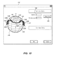
- FIG. 12 One embodiment of a hair transplantation planning system of the present invention that employs the above-described modified Bezier representation for hair line curve construction is depicted in Fig. 12 , in which five control points (or "control hairs") 110A-110E have been specified by a user through a user interface 112 to define an initial hair line curve 111 on a spherical modeling surface 109.
- the user interface 112 allows the user to select a hair line demonstration (or demo) 114 or a hair area demonstration (demo) 116.
- the hair line demo 114 has been selected, which allows for additional user inputs including specifying a density, or spacing 122 (in mm) between implantation locations, and a "randomness" factor 120.
- the actual follicular unit implantation locations along the hair line curve are then automatically determined by the planning module, given a user-specified density in spacing selection 122, with one follicular unit per every 1 mm specified in the user interface screen shot in Fig. 13 .
- the planning system then traverses the curve 111 and places a follicular unit implantation site 126 at every 1 mm on the curve 111. Hair follicles 125 are then added along the proposed hair line 111 by selecting item 118 on the user interface 112.
- the hair follicles 125 are initially generated by the system along a curve 121 that is based on identically spaced control points 120A-120E, that represent the distal tips of the hair follicles 125.
- the length of the hair follicles 125 is assumed to be uniform.
- the distal tip control points 120A-120E may then be manipulated by the user to change a direction of the hair follicles, i.e., by changing the curve 121, without changing curve 111 (points 110A-110E).
- the change in hair follicle direction may be localized to one area of the hair line by only shifting one of the distal control points ("control directions").
- control directions which are unit vectors (i.e., points on a unit sphere)
- the hair line direction and location together completely specify the hair line.
- Further hair lines may be replicated from the initial hair line, and may be added behind the initial hair line to add some thickness.
- the number of times the hair line is replicated may be specified by the user, within a reasonable limit.
- Each one of the curves can be adjusted by the user by adjusting the control points and control directions.
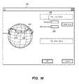
- Fig. 15 depicts the hair follicles 125 of the hair line curve 111, with the density (i.e., spacing input 122) of the implantation locations 126 changed from every 1 mm on the curve 111 to every 3 mm.
- Fig. 16 depicts the hair follicles 125 of the hair line curve 111, with the density at every 3 mm, and with the randomness 120 user-specified at 1.0 mm.
- each follicular unit location 126 is perturbed by 1 mm randomly, and the resulting locations are used by the planning system for the implantation sites, instead of along a uniform curve.
- the hair patch design or "Hair Area Demo” 116, is not shown but is substantially similar to that of the Hair Line Demo 114, wherein each patch is limited by a closed curve that is described by specified control points and direction(s) (hair follicle orientations).
- the hair patch is then filled, digitized, and randomized by the planning system, in accordance with user-specified density and randomness.
- the planning system will output a set of coordinates representing the specific follicular unit harvesting and implantation locations (and, in the later case, the implantation directions), which may used by an automated (e.g., robotic) hair follicular unit transplantation system, such as that described in US patent application serial number 11/380,907 .
- an automated (e.g., robotic) hair follicular unit transplantation system such as that described in US patent application serial number 11/380,907 .
Abstract
Description
- This invention relates generally to planning systems and their use for planning transplantation (i.e., harvesting and implantation) of hair follicular units in a body surface, usually a scalp.
- Hair transplantation procedures are well-known, and typically involve harvesting donor hair grafts from the side and back fringe areas ("donor areas") of the person's scalp, and implanting the harvested follicular units in a bald, top area ("recipient area"). Historically, the harvested grafts were relatively large (3-5 mm), although more recently, the donor grafts may be single follicular units, which are naturally occurring aggregates of 1-3 (and much less commonly, 4-5) closely spaced hair follicles that are distributed randomly over the surface of the scalp.
- In one well-known process, a linear portion of the scalp is removed from a donor area using a scalpel cutting down into the fatty subcutaneous tissue. The strip is dissected (under a microscope) into component follicular units, which are then implanted into a recipient area in respective incisions or puncture holes made using a needle. Forceps may be used to grasp and place the individual follicular unit grafts into the needle puncture locations, although other instruments and methods are known for performing this task.
-
U.S. Patent No. 6,585,746 discloses a hair transplantation system utilizing a robotic system, including a robotic arm and a hair follicle introducer associated with the robotic arm. A video system is used to produce a three-dimensional image of the person's scalp, which is used to plan the scalp locations to receive hair grafts implanted by the follicle introducer under the control of the robotic arm. - In accordance with one aspect of the invention, a method of creating a plan for cosmetic transplantation of follicular units in a body surface of a person includes using a three-dimensional model of a body surface to generate on the model proposed follicular unit implantation locations and hair follicle orientations based on certain control points. The method may further include acquiring images of the body surface, processing the images to produce a three-dimensional model of the body surface, and displaying a graphic rendering of the body surface model on the monitor. A proposed recipient area may be originally identified, subsequently modified, or both, based at least in part on user input. By way of non-limiting examples, the user input may relate to a density or a type (or a mix of type) of follicular units when implanted in an area of the body surface corresponding to the recipient area. By way of further, non-limiting examples the location of the recipient area may relate to an appearance or direction of hair follicles growing from follicular units when implanted in an area of the body surface corresponding to the recipient area.
- The proposed method of the present invention allows to plan a frontal hair line, as well as variously located hair patch areas. By way of non-limiting example, the graphic rendering of the proposed hair follicles locations and orientations may be based, at least in part, on a randomizing of implantation locations of follicular units to be implanted. The method may further include identifying user-defined recipient areas, or patches, in which follicular units are to be implanted.
- The method may further include displaying on the body surface model a donor area for harvesting follicular units, wherein the location of the displayed donor area is based, at least in part, on input received through the user interface. The location of the displayed donor area may alternatively or additionally be based on one or more of (i) an amount of each of a type of existing follicular unit located in a donor area on the actual body surface corresponding to the displayed donor area, as determined from the acquired images, (ii) a minimum density of follicular units to be left remaining in the donor area after selected harvesting of other follicular units has occurred, and (iii) an approximate amount of each type, color, or both, of existing follicular unit to be implanted in an area of the body surface corresponding to the displayed recipient area.
- In some embodiments, the method further comprises identifying locations of follicular units to be harvested from an area on the body surface corresponding to the displayed donor area, identifying locations of implantation sites on the body surface corresponding to the displayed recipient area at which the harvested follicular units are to be implanted, and providing the respective harvest and implantation locations to an automated (e.g., robotic) system for performing the implantation procedure.
- In accordance with another embodiment of the invention, a system for planning for the transplantation of follicular units in a body surface of a person includes a user interface comprising a software-controlled processor and an input device. The system is configured to display on the monitor a three-dimensional model of the body surface. The planning system is further configured to display a proposed recipient area for implanting follicular units on the body surface model, wherein the location of the displayed recipient area may be originally identified, subsequently modified, or both, based at least in part on user input. By way of non-limiting examples, the user input may relate to a density or a type (or a mix of type) of follicular units when implanted in an area of the body surface corresponding to the displayed recipient area. By way of further, non-limiting examples the location of the displayed recipient area may relate to an appearance or direction of hair follicles growing from follicular units when implanted in an area of the body surface corresponding to the displayed recipient area.
- The system may also be configured to identify recipient areas, for example, hair line or one or more hair patches, in which follicular units are to be implanted.
- The planning system may be further configured to display on the body surface model a donor area for harvesting follicular units, wherein the location of the displayed donor area is based, at least in part, on input received through the user interface. The location of the displayed donor area may alternatively or additionally be based on one or more of (i) an amount of each of a type of existing follicular unit located in a donor area on the actual body surface corresponding to the displayed donor area, as determined from the acquired images, (ii) a minimum density of follicular units to be left remaining in the donor area after selected harvesting of other follicular units has occurred, and (iii) an approximate amount of each type, color, or both, of existing follicular unit to be implanted in an area of the body surface corresponding to the displayed recipient area.
- In some embodiments, the planning system identifies locations of follicular units to be harvested from an area on the body surface corresponding to the displayed donor area, and of implantation sites on the body surface corresponding to the displayed recipient area at which the harvested follicular units are to be implanted, and inputs the respective harvest and implantation locations into an automated (e.g., robotic) system for performing the implantation procedure.
- In one embodiment, a system for creating a plan for cosmetic transplantation of hair follicular units in a body surface includes a user interface including a software-controlled processor and a user input device, wherein the processor is configured to display a three-dimensional model of the body surface, and to generate and display on the model proposed follicular unit implantation locations and hair follicle orientations based on specified control points and orientations at the control points. In accordance with this embodiment, a user may interactively adjust the control point locations and orientations to thereby correspondingly adjust the proposed follicular unit implantation locations and hair follicle orientations.
- In one embodiment, a system for creating a plan for cosmetic transplantation of hair follicular units in a body surface includes a user interface including a software-controlled processor and a user input device, wherein the processor is configured to display on a three-dimensional model of the body surface one or more proposed follicular unit recipient areas. In accordance with this embodiment, the user interface is configured to generate and display one or more input menus for receiving user inputs through the user input device for defining and adjusting the one or more proposed recipient areas.
- In one embodiment, a method for creating a plan for cosmetic transplantation of hair follicular units in a body surface includes displaying a three-dimensional model of the body surface, generating and displaying on the model proposed follicular unit implantation locations and hair follicle orientations based on specified control points and orientations at the control points, and interactively adjusting the control point locations and orientations to thereby correspondingly adjust the proposed follicular unit implantation locations and hair follicle orientations.
- In one embodiment, a system for creating a plan for removing hair follicular units from a body surface includes a user interface including a software-controlled processor and a user input device, wherein the processor is configured to display a three dimensional model of the body surface, and to generate and display a proposed hair removal area on the body surface model. In accordance with this embodiment, the user interface is configured to generate and display one or more input menus for receiving user inputs for adjusting the proposed hair removal area.
- In one embodiment, a method for creating a plan for removing hair follicular units from a body surface includes displaying a three dimensional model of a body surface, displaying a proposed hair removal area on the body surface model, and generating and displaying one or more input menus for receiving user inputs for adjusting the proposed hair removal area.
- Other and further embodiments, objects and advantages of the invention will become apparent from the following detailed description when read in view of the accompanying figures.
- Embodiments of the invention are illustrated by way of example and not limitation in the figures of the accompanying drawings, in which like references indicate similar elements, and in which:
-
Figs. 1A and 1B are images (pictures) of a front and side profile of a person's head. -
Figs. 2-6 are respective monitor screen shots of a user interface generated by modeling software used for creating a three-dimensional surface model of the person's head based on the acquired images, in accordance with one embodiment. -
Fig. 7 is a further monitor screen shot of a user interface generated by the modeling software for creating a three-dimensional model based on selected appearance input parameters instead of acquired images. -
Figs. 8A and 8B are respective front and back perspective views depicting a completed three-dimensional surface model of the person's head based on the acquired images. -
Fig. 9 depicts a proposed front hair line boundary overlaying the body surface model ofFigs. 8A and 8B . -
Fig. 10 depicts a proposed hair patch area overlaying the body surface model ofFigs. 8A and 8B . -
Fig. 11 is a monitor screen shot of a user interface generated by a planning model constructed according to one embodiment. -
Fig. 12 is another monitor screen shot generated by a planning model constructed according to one embodiment, depicting a rudimentary hair line design employing a plurality of control points. -
Fig. 13 is a further monitor screen shot depicting the rudimentary hair line ofFig. 12 , and further displaying graphically rendered hair follicles extending from potential implantation locations along the boundary. -
Fig. 14 is a still further monitor screen shot depicting the rudimentary hair line ofFig. 12 , in which the angle(s) at which the control hair follicles displayed inFig. 13 extend from the implantation locations have been modified. -
Fig. 15 is yet another monitor screen shot depicting the rudimentary hair line ofFig. 12 , in which the density of the implantation locations displayed inFig. 13 has been modified. -
Fig. 16 is a still further monitor screen shot depicting the rudimentary hair line ofFig. 12 , in which user-specified level of distribution randomness has been applied to the implantation locations displayed inFig. 13 . -
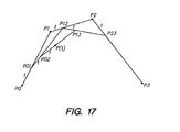
Fig. 17 illustrates a technique used to design arbitrary shaped curves based on user-specified control points (e.g., for planning a front hair-line boundary), in accordance with one embodiment. -
U.S. Provisional Patent Application andserial numbers 60/753,60260/764,173 - As described in Bodduluri et al, the aesthetic result of a hair transplantation procedure depends in part on implanting the grafts in natural-looking patterns. A computer can efficiently "amplify" a surgeon's skill by "filling in the blanks" among a small fraction of the implant sites for which the surgeon determines graft location and orientation. Achieving a natural-looking hair line is particularly important for a good aesthetic result. Instead of painstakingly making incisions for all of the near-hairline implant sites, the surgeon indicates a few hairline implant locations and orientations and the computer fills in the rest by interpolating among the designated sites, using the imaging system to identify and avoid existing follicular units.
- Bodduluri et al illustrates an algorithm using control points to design natural looking hairline. A curve is designed using control points based on, for example, b-spline cubic polynomials. The control points are specified by the operator. The orientation of the hair at each of the control points is specified. Points along the curve are identified at a given spacing, for instance, by interpolation. The locations of the points along the curve may be randomized to make a natural looking hair line. The amount of randomization may be user-specified or computer-generated. It is preferable that the follicular unit orientations are not randomized but are interpolated, for example, the same way a cubic spline is generated. Randomization of the location and interpolation of the orientation create more natural looking implants.
- Natural looking randomness is important in both the critical hairline region and in the balance of the recipient sites. This can be achieved using a procedure illustrated in Bodduluri et al, wherein a surface is designed using control points based on, for example, b-spline cubic surfaces. Again, the orientation of the hair at each of the control points is specified. Implant points along the surface are identified at a given spacing. The locations of the points along the surface may be randomized to make a natural looking hair distribution. The amount of randomization may be user-specified or computer-generated. Again, the orientation of the respective follicular units is preferably not randomized, but interpolated the same way a cubic spline surface is generated. Randomization and interpolation schemes are known in the art, and can be adapted for this method.
- Bodduluri et al shows an example of an automatic guidance feature of the robotic system, including the step of planning implant locations and orientations with respect to global landmarks (e.g., existing hairs, tattoos, or other distinguishing features). The robot is then moved to register landmarks on the person. The register information can be stored in memory for reference. The robot can make use of the registered landmarks as reference points for recognizing its position relative to the working surface. The robot is moved to each of the implant location and orientation with respect to the global landmarks. The global landmarks provide a global reference for global movements. The location and orientation are fine-tuned based on the nearby landmarks such as neighboring preexisting hairs or newly implanted hairs. The nearby landmarks provide a local reference for local movements.
- Next, a treatment plan is input into the computer. For example, the treatment plan is a prescribed plan designed to transplant hair follicles from a first region (harvest region) to a target region (implant region). In such cases, the treatment plan may include one or more parameters, such as a number of hair follicles to be removed/implanted, location of harvest region, location of implant region, a degree of randomness associated with targeted implant locations, spacing between adjacent targeted implant locations, depth of follicle, depth of implant, person identification, geometric profile of harvest region, geometric profile of implant region, marker location(s), and density of targeted implant locations.
- Various techniques may be used to input the treatment plan into the computer. In the illustrated embodiments in Bodduluri et al, the treatment plan may be inputted using a user interface that includes a monitor and a keyboard. Alternatively, the treatment plan may be inputted using a storage device, such as a diskette or a compact disk. In other embodiments, the treatment plan may be downloaded from a remote server, or from a combination of the forgoing techniques. For example, some parameters may be inputted into the computer using a diskette, while other parameters may be inputted using the user interface. In some embodiments, one or more parameters of the treatment plan may be determined in real time (e.g., during a treatment session).
- After the treatment plan has been input into the computer, the computer then registers the treatment plan with a person. In some embodiments, such may be accomplished by using one or more cameras to identify one or more markers on the person. The marker may be a reflector that is secured to the person, an ink mark drawn on the person, or an anatomy of the person. The identified marker(s) may be used to determine a position and/or orientation of a target region on the person.
- In accordance with various embodiments of the invention, a system for planning a procedure for the transplantation of follicular units in a body surface (e.g., a scalp) of a person comprises a user interface, including, for example, a software-controlled processor, a monitor, and an input device. These components are common to virtually all modern computer systems, whether a stand alone (e.g., "personal") computer system, or in a system employing a centralized server with multiple remote terminal(s). It will be appreciated that embodiments of the planning system are preferably (if not exclusively from a practical point of view) software implemented, and may be run on any computer system having the basic components (processor, monitor, input device), so long as such computer system is equipped with sufficient available memory and an appropriate graphic generation and display capability.
- It will also be appreciated that embodiments of the invention may be implemented over the internet, e.g., with a user of such system employing his or her home computer as at least a part of the user interface (monitor and input device) that interacts with a remote server or computer. In such an internet-based planning system, the software that implements and controls the user interface may reside in whole or part on the user's computer or on the remote server/computer, preferably transparent to the user. In one such embodiment, the remote server downloads one or more software modules to the user's computer for temporary or permanent use.
- Exemplary embodiments of a software implemented and controlled user interface for planning a follicular unit transplantation procedure will now be described in conjunction with the accompanying figures. It will be appreciated that various and multiple variations of the described embodiments may be implemented without departing from the general scope of the invention, which is set forth in the appended claims.
- With reference to
Figs. 1A and 1B , images are acquired of a body surface of a person, in this case, a front view 20 (Fig. 1A ) and a side view 22 (Fig. 1B ) of the person's head (and, in particular, scalp), for which the subject transplantation procedure is being planned. By way of non-limiting example, theimages side views - With reference generally to
Figs. 2-6 , the acquiredimages - With more specific reference to
Fig. 2 , a monitor screen shot from the user interface taken during use of the FaceGen Modeller program includes a series of pull-downmenus 26 related to construction of a model of a human face. The menu "PhotoFit" 28 has been selected, resulting in the display of a frontal image 30 (in this case, image 20), a left profile image 36 (an optional input; in this case, not provided) and a right profile image (also optional; in this case, side image 22) of the person. The software program displaysrespective front 32,left profile 33, andright profile 40 images of a model as an example for users of the system. Once theimages interface menu inputs 34 and 42), a subsequent screen shot menu is provided (i.e., after "clicking" on the "next" menu field item 44). - Referring to field 46 in
Fig. 3 , in order to generate a three-dimensional model of the person's head/scalp, the user assigns a series of feature points 52 on the frontal image 20 (designated by reference numeral 48), based on the provided example 50. In brief, the feature points 52 are placed at distinct physical locations (e.g., corners of the mouth, nose, chin, ears, etc.) of the person's face. Theimage 48 may be rotated using therespective inputs 54. As shown inFig. 4 , the modeling software allows the user to enlarge the frontal image (designated by reference number 58) for accurate placement of the feature points 52. Referring toFigs. 5 and6 , the process is repeated for assigning feature points to the side profile image(s), in this case to theright profile image 60 inFig. 5 , and enlarged 64 inFig. 6 ), with anexample model picture 62 provided for illustration. Further information regarding generation of a three-dimensional model based on the acquired front and side images may be ascertained directly from the FaceGen Modeller software. - With reference to
Fig. 7 , in an alternate embodiment in which acquired images of the person's head/scalp (or other applicable body surface) are not provided, the modeling software is configured to generate (by selecting menu option "generate" 64) a three-dimensional model (designated as 24') based on inputs relating to selected characteristics, such asrace 66 and other characteristics selected throughmenus - In some embodiments, further input information is provided to the planning system in addition to generating the body surface model. For example, particular features specific to hair follicles (e.g., color or coarseness) may be derived from the images and/or input through the user interface. Further information may be either user input or determined from the acquired images using image processing, such as geometric shape of the body surface (e.g., person's head), existing hair lines, and a number of each type (i.e., single or multiple follicle) and color (e.g., dark, light, gray, etc.) of follicular unit that are available for harvesting. It will be appreciated that the three dimensional model can alternatively be generated by a number of other methods, for example, using a 3D laser scanner and/or by stiching multiple digital images together. The system of embodiments of the present invention will use the three dimensional information in the same way, without regard to how it is generated.
- Referring to
Figs. 8A and 8B , whether from the acquired images, or through other descriptive feature inputs, the modeling software generates and displays on the user interface monitor of the planning system a three-dimensional model 24 of the person's head/scalp. For purposes of illustration, the model generated inFigs. 8A and 8B exhibits characteristic male-pattern baldness, including a baldtop region 74, andpopulated side 72 and back 76 regions. - Referring to
Figs. 9 and 10 , based on one or more physical features and information determined from processing the acquiredimages recipient areas 82 for implanting follicular units. An initial location of a proposed front boundary (or "hair line") 78 may be initially identified by the system, or generated based (at least in part) on user input received through the user interface. In either case, it may be modified by the user, as indicated by thearrows 80 e.g., by using a convention click and drag motion of a computer mouse, until thehair line 78 is in a desired location. Once thehair line 78 is established, one or more separate regions (or "patches") 85 behind the hair line may also be initially identified by the system, or generated based (at least in part) on user input received through the user interface. As with thehair line 78, the boundaries of thepatches 85 may be modified by the user, as indicated by thearrows 84. - In some embodiments of the invention, the attending physician or operator can specify where a follicular unit needs to be implanted and at what angle, i.e., its relative location (or "implantation site"), orientation, and depth. This specification of the location, orientation and/or depth of a hair follicle to be implanted may be carried out by a treatment planning system. Alternatively, during the implanting mode, when the camera(s) are viewing the recipient area of the scalp, the attending operator may use a user interface (e.g., a conventional computer mouse) to specify the implant location and/or position and/or orientation and/or implant depth. Alternatively, the operator can point to location on the scalp by placing a temporary fiducial, such as an ink mark or a pointer that can be visualized, identified, and measured by the image processing system. Further, orientation can be specified directly on the computer monitor as a combination of two angles, such as rotation about x-axis and a rotation about y-axis (assuming that z-axis is along the needle), or by placing an elongated pointer on the scalp, which the image processing system can visualize and measure the angles.
- By way of non-limiting examples, input received through the user interface for establishing or modifying the hair line and inner patch boundaries may relate to one or more of a resulting density of the follicular units after they are implanted in the recipient area, a direction of hair follicles that will grow out from the implanted follicular units, and an overall appearance (i.e., hair style) of the hair follicles growing out from the implanted follicular units. Other factors, such as a geometric shape of the body surface, an ethnicity of the person, an age of the person, a gender of the person, and/or existing hair lines, densities and follicle color(s) on the body surface. One or more parameters relating to existing follicular units in an identified donor area of the body surface may also be considered, such as an amount of each type (e.g., single or multiple follicle), color, and a relative coarseness of hair follicles growing from the existing follicular units.
- In particular, the available quantity of single follicle follicular units available for harvesting may also play a role in defining the hair line of the recipient area, since the single follicle type of unit is predominantly found in natural front hair lines.
U.S. patent application serial number 11/467,283, filed August 25, 2006 - Referring to
Fig. 11 , in one embodiment, the user-interface of the planning system may generate and display input menus for the user during a planning process. Such menus may includes, but are not limited to ahair design studio 96,hair donor studio 100 and hair finalizestudio 104. Thehair design studio 96 may comprise, by way of non-limiting example, aninput menu 98 for receiving user inputs relating to specific hair line and hair patch (or "hair area") planning for the recipient area(s), along with related input parameters, and an automatic ("auto hair") feature in which case the hair line and patch areas are identified, preferably including specific implantation locations, by the system without needing further user input. - The
hair donor studio 100 may comprise, by way of non-limiting example, aninput menu 102 for receiving user inputs relating to a proposeddonor area 90, including related parameters and an automatic ("auto donate") feature in which case the donor area is identified by the system without needing further user input. The hair finalizestudio 104 may comprise, by way of non-limiting example, aninput menu 106 for receiving user instructions relating to saving, transmitting, receiving, reviewing, etc., a completed or partially completed transplantation procedure plan. The display inFig. 11 also includes a four-way split screen of images, including afirst image 89 of the initial person head model, asecond image 91 of the head model during the hair line and patch planning process, athird image 88 of the donor planning process (including a currently identified donor region 90), and afourth image 92 of a graphic representation of the person, post-transplantation 94 (i.e., with an artistic rendering of the resulting hair style of the person). - A person's hair line is formed by the respective locations at which hair follicles emerge from the scalp, as well as the direction(s) relative to the surface of the scalp at which the hair follicles emerge, along the boundary line(s) of the region(s) which have existing or planned (implanted) hair follicular units. Thus, designing a suitable "hair line" curve is a crucial part of achieving a desired, resulting appearance from a hair follicular unit transplantation procedure. In accordance with embodiments of invention, the respective location and direction of the follicular units to be implanted along the hair line boundary is preferably specified along a curve, in order to complete the design of the hair line. This "hair line curve" can be designed in a similar manner as designing a curve in the field of computer aided design, for example, using a well-known technique called a "Bezier representation," or modifications thereof. A Bezier representation is a way of designing arbitrarily-shaped curves based on a specified number of "control points" that will define the curve.
- By way of example, with reference to
Fig. 17 , given four control points, P0, P1, P2, P3, a curve function P(t) may be specified, where t is a parameter that varies from 0 to 1. The point on the curve may be calculated analytically, or may be obtained using a graphical construction technique, known as de Casteljau's construction. The steps of the curve construction are as follows: - (1) First, the line segment P0P1 is subdivided into two parts, based on the relationship, P0P01: P01P1 is t: (1-t). That is, find the point P01 that subdivides the line segment P0P1 into subparts t and (1-t).
- (2) Similarly, find the point P12 on the line segment P1P2 and point P23 on the line segment P2P3.
- (3) Similarly, find the point P02 on the line segment P01P12 and the point P13 on the line segment P12P23.
- (4) Finally, find the point P(t) that subdivides, in the same fashion, the line segment P02P13.
- As may be observed in
Fig. 17 , as t varies from 0 to 1, a curve is established that extends from P0 to P3, that is, P(0) = P0 and P(1) = P3. Moreover, the line P0P1 is tangential to the curve at P0 and the line P2P3 is tangential to the curve at P(3). - Thus, given two points, P0 and P1, finding every point P(t) on the line segment that extends from P0 to P1 is called linear interpolation, given by the expression P(t) = (1-t) P0 + t P1. Note that when t = 0, P(t) = P0 and when t = 1, P(t) = P1. In the (so-called) subdividing each of the line segments described in the above construction, finding a point that subdivides the line segment given t is the same as finding the point on the line segment that corresponds to t by the linear interpolation formula. This construction (or linear interpolation idea) works nicely with an arbitrary specification of the control points P0 through P3 in a plane, where the resulting curve remains in the plane. The construction also works well where one specifies the control points in three dimensions. However, if the four points are specified on a curved surface, the resulting curve does not necessarily stay on the curved surface. That is, if one specifies all the control points on a sphere, then the resulting curve constructed using the above technique does not keep the curve on the sphere.
- Thus, embodiments of the planning system according to the present invention preferably employ a modified construction, which keeps the curve on the surface of the planning sphere. Consider two points P0 and P1 lying on a unit sphere, with a center C. The three points together form a plane, and the plane intersects the sphere in a great circle. The two radii CP0 and CP1 subtend an angle theta. Every point on the curve between the two points P0 and P1 can now be parameterized by P(t) such that PoP(t) form an angle theta, and P(t)P1 form an angle (1-t) theta, at the center C. This interpolation scheme is called spherical linear interpolation, in which the resulting curve P(t) goes from P0 to P1 as t varies from 0 to 1. Thus, given four points on a sphere P0, P1, P2, and P3, a Bezier curve can be designed that lies on the sphere similar to the planar construction described earlier, except the linear subdivision (linear interpolation) is replaced by angular subdivision (spherical linear interpolation).
- It will be appreciated that an advantage of using control points is that a few user-input points may represent an otherwise complicated set of points forming the hair line curve. Thus, in designing a hair line curve, the user needs to only adjust the control points interactively until the resulting curve is the desired curve that the user is seeking. In a Bezier formulation, the curve passes through the first and the last control points but not the middle ones. The middle control points specify the slope of the curve at the beginning of the curve and at the end of the curve. Specifying points on the curve and the slopes of the curve may not be intuitive to the user, and it may be preferable to instead specify control points that lie on the curve. Such a formulation exists, and it is called Cardinal spline.
- In the case of a Cardinal spline, a set of control points P0, P1 ... Pn are specified on the curve. For a pair of the control points Pi and Pi+1, the Bezier control points are as follows: B0 = Pi; B3 = Pi+1. B1 is chosen such that the respective slope of the curve at B0 is defined by Pi+1 and Pi-1, B2 is chosen such that the slope of the curve at B3 is defined by Pi+2 and Pi. The length of the tangent can be adjusted to alter the behavior of the curve. A Catmull ROM Spline is a special case of cardinal spline, wherein a specific length of the tangent is used in calculating B1 and B2. Using these four control points, a Bezier curve can be calculated that goes through Pi-1 and Pi, as per the Bezier formulation described earlier. The Cardinal spline formulation guarantees that the curve passes through all the control points. This curve on the sphere can be projected on to the surface of the person's 3D body surface (haed/scalp) model to design the desired hair line for the person.
- A more detailed explanation and further information regarding Bezier curves may be found at http://en.wikipedia.org/wiki/B%C3%A9zier_curve. A more detailed explanation and further information regarding Cardinal splines may be found at http://en.wikipedia.org/wiki/Cardinal_spline. A more detailed explanation and further information regarding Catmull-Rom splines may be found at http://en.wikipedia.org/wiki/Catmull-Rom_spline and http://ibiblio.org/e-notes/Splines/Cardinal.htm.
- One embodiment of a hair transplantation planning system of the present invention that employs the above-described modified Bezier representation for hair line curve construction is depicted in
Fig. 12 , in which five control points (or "control hairs") 110A-110E have been specified by a user through auser interface 112 to define an initialhair line curve 111 on aspherical modeling surface 109. Theuser interface 112 allows the user to select a hair line demonstration (or demo) 114 or a hair area demonstration (demo) 116. In the illustrated embodiments, thehair line demo 114 has been selected, which allows for additional user inputs including specifying a density, or spacing 122 (in mm) between implantation locations, and a "randomness"factor 120. - With reference to
Fig. 13 , once thehair line curve 111 has been designed to the user's initial satisfaction, i.e., by manipulation of, or adding to, control points 110A-110E, the actual follicular unit implantation locations along the hair line curve are then automatically determined by the planning module, given a user-specified density inspacing selection 122, with one follicular unit per every 1 mm specified in the user interface screen shot inFig. 13 . The planning system then traverses thecurve 111 and places a follicularunit implantation site 126 at every 1 mm on thecurve 111.Hair follicles 125 are then added along the proposedhair line 111 by selectingitem 118 on theuser interface 112. In the illustrated embodiment, thehair follicles 125 are initially generated by the system along acurve 121 that is based on identically spaced control points 120A-120E, that represent the distal tips of thehair follicles 125. The length of thehair follicles 125 is assumed to be uniform. - Referring to
Fig. 14 , the distal tip control points 120A-120E may then be manipulated by the user to change a direction of the hair follicles, i.e., by changing thecurve 121, without changing curve 111 (points 110A-110E). As will be appreciated, the change in hair follicle direction may be localized to one area of the hair line by only shifting one of the distal control points ("control directions"). Thus, by using the control directions, which are unit vectors (i.e., points on a unit sphere), one can obtain the direction of a givenhair follicle 125 along thehair line 111 using the same formulation described above for the hairline implantation locations 126. The hair line direction and location together completely specify the hair line. Further hair lines may be replicated from the initial hair line, and may be added behind the initial hair line to add some thickness. The number of times the hair line is replicated may be specified by the user, within a reasonable limit. Each one of the curves can be adjusted by the user by adjusting the control points and control directions. -
Fig. 15 depicts thehair follicles 125 of thehair line curve 111, with the density (i.e., spacing input 122) of theimplantation locations 126 changed from every 1 mm on thecurve 111 to every 3 mm.Fig. 16 depicts thehair follicles 125 of thehair line curve 111, with the density at every 3 mm, and with therandomness 120 user-specified at 1.0 mm. In other words, eachfollicular unit location 126 is perturbed by 1 mm randomly, and the resulting locations are used by the planning system for the implantation sites, instead of along a uniform curve. - The hair patch design, or "Hair Area Demo" 116, is not shown but is substantially similar to that of the
Hair Line Demo 114, wherein each patch is limited by a closed curve that is described by specified control points and direction(s) (hair follicle orientations). The hair patch is then filled, digitized, and randomized by the planning system, in accordance with user-specified density and randomness. It will also be appreciated that, in addition to graphic renderings of the person's scalp following the implantation, the planning system will output a set of coordinates representing the specific follicular unit harvesting and implantation locations (and, in the later case, the implantation directions), which may used by an automated (e.g., robotic) hair follicular unit transplantation system, such as that described inUS patent application serial number 11/380,907 . - The foregoing illustrated and described embodiments of the invention are susceptible to various modifications and alternative forms, and it should be understood that the invention generally, as well as the specific embodiments described herein, are not limited to the particular forms or methods disclosed, but also cover all modifications, equivalents and alternatives falling within the scope of the appended claims. By way of non-limiting example, it will be appreciated by those skilled in the art that the planning systems and methods of their use are not limited to the use of an automated transplantation (e.g., robotic) system, and that the planning system and methods may also be used for planning transplantation procedures employing semi-automated, and manual systems and apparatus for performing the transplantation procedure.
- The invention is further described by the following clauses:
- 1. A system for creating a plan for cosmetic transplantation of hair follicular units in a body surface, comprising:
- a user interface including a software-controlled processor and a user input device, wherein the processor is configured to display a three-dimensional model of the body surface, and to generate and display on the model proposed follicular unit implantation locations and hair follicle orientations based on specified control points and orientations at the control points,
- wherein a user may interactively adjust the control point locations and orientations to thereby correspondingly adjust the proposed follicular unit implantation locations and hair follicle orientations.
- 2. The system of
clause 1, wherein the processor is further configured to process images of the body surface to generate the three-dimensional model. - 3. The system of
clauses - 4. The system of any of clauses 1-3, wherein follicular unit implantation locations and orientations are generated from the control points using interpolation techniques.
- 5. The system of clause 4, wherein follicular unit implantation locations are further randomized.
- 6. The system of any of clauses 1-5, wherein the user may interactively adjust one or more of a respective density, direction, implant depth, degree of randomization, overall appearance of the follicular units in the proposed follicular unit implantation locations.
- 7. The system of any of clauses 1-6, wherein the proposed follicular unit implantation locations comprise a planned hair line.
- 8. The system of any of clauses 1-6, wherein the proposed follicular unit implantation locations comprise a planned boundary of a hair patch area.
- 9. The system of
clause 3, wherein the processor is configured to determine and display on the model proposed additional follicular unit implantation locations and hair follicle orientations arranged in a configuration of one or more additional hair lines substantially replicating the planned hair line. - 10. The system of clause 9, wherein the user may specify the number of times the hair line is replicated.
- 11. The system of clause 8, wherein the processor is configured to determine and display on the model proposed additional follicular unit implantation locations and hair follicle orientations within an interior of the hair patch area defined by the boundary in accordance with one or more user-specified parameters.
- 12. The system of any of clauses 1-11, wherein the hair follicle orientations comprise directions relative to the body surface of hair follicles growing from respective implanted hair follicular units.
- 13. The system of
clause 1, wherein the proposed follicular unit implantation locations are generated using a curve construction based on the locations of the control points. - 14. The system of
clause 1, wherein the proposed follicular unit implantation locations are generated using a modified interpolated curve construction. - 15. The system of any of clauses 1-14, wherein the processor is configured to display on the body surface model a graphic rendering of hair follicles growing from planned follicular unit implantation locations.
- 16. The system of any of clauses 1-15, wherein the processor is configured to display on the body surface model a proposed boundary of a donor area for harvesting follicular units, and wherein the proposed donor area boundary is originally determined, subsequently modified, or both, based on input received via the user input device.
- 17. The system of clause 16, wherein the proposed donor area boundary is determined based at least in part on one or more of
an amount of each of a type of existing follicular unit available for harvesting from the donor area,
an amount of each of a type of existing follicular unit to be implanted, and
a minimum density of follicular units to be left remaining in the donor area after selected harvesting of other follicular units. - 18. The system of
clause 1, wherein the plan is inputted using a storage device, or a remote server. - 19. The system of
clause 1, wherein the model of the body surface further comprises additional features specific to hair follicles that are derived from the images, input through the user interface, or both. - 20. The system of
clause 1, wherein one or more of the proposed follicular unit implantation locations are generated using a Bezier representation technique, or a Cardinal spline curve construction. - 21. The system of
clause 1, wherein the proposed follicular unit implantation locations and orientations are based at least in part on an attribute of existing follicular units in an identified donor area of the body surface and selected from the group comprising
a mix of type of follicular unit,
a quantity of each type of follicular unit,
a relative coarseness of hair follicles growing from the follicular units, a direction of hair follicles growing from the follicular units,
a color of hair follicles growing from the follicular units, and
a randomness of the follicular units. - 22. A system for creating a plan for cosmetic transplantation of hair follicular units in a body surface, comprising:
- a user interface including a software-controlled processor and a user input device, wherein the processor is configured to display on a three-dimensional model of the body surface one or more proposed follicular unit recipient areas,
- wherein the user interface is configured to generate and display one or more input menus for receiving user inputs through the user input device for defining and adjusting the one or more proposed recipient areas.
- 23. The system of
clause 22, wherein the one or more recipient areas comprise a hair line. - 24. The system of
clause 22 or 23, wherein the one or more recipient areas comprise a hair patch area. - 25. The system of any of clauses 22-24, wherein the one or more user-interface input menus include a hair design menu, a hair donor menu, and hair finalize menu.
- 26. The system of clause 25, wherein the hair design menu is configured to receive user inputs relating to one or more of:
- hair line planning,
- hair patch area planning, and
- a user-selected request for the system to automatically generate one or both of a planned hair line, and a planned patch area.
- 27. The system of
clause 26, wherein the processor is configured to generate and display on the model proposed follicular unit implantation locations and hair follicle orientations based on user inputs received via respective hair line planning and hair patch area planning menus. - 28. The system of clause 25, wherein the hair design menu is configured to receive user inputs relating to donor area planning, including a user-selected request for the system to automatically generate a planned donor area.
- 29. The system of clause 25, wherein the hair finalize menu is configured to receive user inputs relating to one or more of saving, transmitting, receiving and reviewing a completed or partially completed transplantation procedure plan.
- 30. A method for creating a plan for cosmetic transplantation of hair follicular units in a body surface, comprising:
- displaying a three-dimensional model of the body surface,
- generating and displaying on the model proposed follicular unit implantation locations and hair follicle orientations based on specified control points and orientations at the control points; and
- interactively adjusting the control point locations and orientations to thereby correspondingly adjust the proposed follicular unit implantation locations and hair follicle orientations.
- 31. The method of
clause 30, further comprising processing images of a body surface to generate the three-dimensional model of the body surface. - 32. The method of
clause 30 or 31, wherein control points and orientations at the control points are user selected, automatically generated, or specified by combination of both. - 33. The method of clauses 30-32, further comprising using interpolation techniques to generate follicular unit implantation locations and orientations.
- 34. The method of clauses 30-33, further comprising randomizing follicular unit locations.
- 35. The method of
clause 30, further comprising interactively adjusting one or more of a respective density, direction, implant depth, a degree of randomization, and overall appearance of the follicular units in the proposed follicular unit implantation locations. - 36. The method of clauses 30-35, wherein the proposed follicular unit implantation locations comprise a planned hair line.
- 37. The method of clauses 30-35, wherein the proposed follicular unit implantation locations comprise a planned boundary of a hair patch area.
- 38. The method of
clause 36, further comprising determining and displaying on the model proposed additional follicular unit implantation locations and hair follicle orientations arranged in a configuration of one or more additional planned hair lines substantially replicating the planned hair line. - 39. The method of
clause 34, further comprising determining and displaying on the model proposed additional follicular unit implantation locations and hair follicle orientations within an interior of the hair patch area defined by the boundary in accordance with one or both of a density and a degree of randomization. - 40. The method of any of clauses 30-39, wherein one or both of the control point locations and hair follicle orientations are initially generated by the processor.
- 41. The method of
clause 30, wherein the proposed follicular unit implantation locations are generated using a curve construction based on the locations of the control points. - 42. The method of
clause 30, wherein the proposed follicular unit implantation locations are generated using a modified interpolated curve construction. - 43. The method of any of clauses 30-42, further comprising displaying on the body surface model a graphic rendering of hair follicles growing from planned follicular unit implantation locations.
- 44. The method of any of clauses 30-43, further comprising displaying on the body surface model a proposed boundary of a donor area for harvesting follicular units.
- 45. The method of
clause 44, wherein the proposed donor area boundary is originally determined, subsequently modified, or both, based on user input. - 46. The method of
clause 44, wherein the proposed donor area boundary is determined based at least in part on one or more of
an amount of each of a type of existing follicular unit available for harvesting from the donor area,
an amount of each of a type of existing follicular unit to be implanted, and
a minimum density of follicular units to be left remaining in the donor area after selected harvesting of other follicular units. - 47. The method of any of clauses 30-46, wherein the body surface model is generated by a 3D scanner.
- 48. The method of any of clauses 30-47, wherein the model of the body surface further comprises additional features specific to hair follicles that are derived from the images, input by a user, or both.
- 49. The method of
clause 30, wherein one or more of the proposed follicular unit implantation locations are generated using a Bezier representation or a Cardinal spline curve construction. - 50. The method of
clause 30, wherein the proposed follicular unit implantation locations and orientations are based at least in part on an attribute of existing follicular units in an identified donor area of the body surface and selected from the group comprising
a mix of type of follicular unit,
a quantity of each type of follicular unit,
a relative coarseness of hair follicles growing from the follicular units, a direction of hair follicles growing from the follicular units,
a color of hair follicles growing from the follicular units, and
a randomness of the follicular units. - 51. A system for creating a plan for removing hair follicular units from a body surface, comprising:
- a user interface including a software-controlled processor and a user input device, wherein the processor is configured to display a three dimensional model of the body surface, and to generate and display a proposed hair removal area on the body surface model, and
- wherein the user interface is configured to generate and display one or more input menus for receiving user inputs for adjusting the proposed hair removal area.
- 52. The system of clause 51, wherein the one or more input menus include an input menu for receiving user inputs through the user input device for initially defining the proposed hair removal area.
- 53. The system of clause 51, wherein the user interface is configured to automatically generate the proposed hair removal area.
- 54. The system of clause 51, wherein the user interface generates the proposed hair removal area based at least in part on a density of existing follicular units available for removal from the proposed hair removal area.
- 55. The system of
clause 53 or 54, wherein the user interface generates the proposed hair removal area based at least in part on a minimum density of follicular units to be left remaining in the proposed hair removal area after selected removal of other follicular units. - 56. The system of any of clauses 53-55, wherein the user interface generates the proposed hair removal area based at least in part on an amount of each of a type of existing follicular unit available for removal from the proposed hair removal area.
- 57. The system of any of clauses 53-56, wherein the user interface generates the proposed hair removal area based at least in part on an amount of each of a type of existing follicular unit to be implanted in another area of the body surface.
- 58. A method for creating a plan for removing hair follicular units from a body surface, comprising:
- displaying a three dimensional model of a body surface;
- displaying a proposed hair removal area on the body surface model; and
- generating and displaying one or more input menus for receiving user inputs for adjusting the proposed hair removal area.
- 59. The method of
clause 58, the one or more input menus including an input menu for receiving user inputs through the user input device for initially defining the proposed hair removal area. - 60. The method of
clause 58, further comprising automatically generating the proposed hair removal area. - 61. The method of
clause 58, further comprising generating the proposed hair removal area based at least in part on a density of existing follicular units available for removal from the proposed hair removal area. - 62. The method of
clause 58, further comprising generating the proposed hair removal area based at least in part on a minimum density of follicular units to be left remaining in the proposed hair removal area after selected removal of other follicular units. - 63. The method of
clause 58, further comprising generating the proposed hair removal area based at least in part on an amount of each of a type of existing follicular unit available for removal from the proposed hair removal area. - 64. The method of
clause 58, further comprising generating the proposed hair removal area based at least in part on an amount of each of a type of existing follicular unit to be implanted in another area of the body surface.
Claims (15)
- A method for creating a plan for transplantation of hair follicular units, the method comprising:generating on a three-dimensional model of a body surface a boundary curve having follicular unit implantation locations and hair follicle orientations, at least some of the follicular unit implantation locations and the hair follicle orientations automatically generated based on specified control points and orientations at the control points;adjusting a location and/or orientation of at least one of the control points to cause a processor to generate an adjusted boundary curve, wherein 1) if the location of the at least one of the control points is adjusted, more than one of the follicular implantation locations is adjusted, or 2) if the orientation of the at least one of the control points is adjusted, orientations of more than one of the hair follicles of the boundary curve are adjusted.
- The method of claim 1, wherein adjusting comprises using a click and drag motion of an input device.
- The method of any one of claims 1-2, wherein the control points and/or orientations at the control points are user selected, automatically generated, or specified by a combination of both.
- The method of any one of claims 1-3, further comprising using interpolation techniques to generate the follicular unit implantation locations and/or orientations, preferably wherein at least one of the proposed follicular unit implantation locations and/or at least one of the hair follicle orientations is calculated analytically, generated using a graphical construction technique, a Bezier technique, Cardinal spline technique, or b-spline interpolation technique.
- The method of any one of claims 1-4, further comprising adjusting one or more of a respective density, direction, implant depth, a degree of randomization, or overall appearance of the follicular units in the proposed follicular unit implantation locations.
- The method of any one of claims 1-5, the method comprising one or a combination of the following techniques: inputting the plan via a user interface, inputting or downloading the plan from a storage device or a remote server, determining the plan in real time.
- The method of any one of claims 1-6, further comprising registering the plan with the body surface, preferably using one or more cameras, and preferably identifying and registering one or more markers or landmarks on the body surface.
- The method of any one of claims 1-7, further comprising transferring the plan to a robotic system for hair transplantation.
- The method of any one of claims 1-8, wherein the method is implemented over an internet, preferably interacting with a remote server or computer, and preferably downloading one or more software modules from a remote location for temporary or permanent use.
- The method of any one of claims 1-9, further comprising generating and displaying the three-dimensional model of the body surface, preferably processing multiple images of the body surface, and preferably based on inputs relating to one or more characteristics from the following list: race, gender, age, ethnicity, color of hair, density, coarseness of hair, feature points from one or more of the multiple images, shape of a head or body surface.
- The method of any one of claims 1-10, further comprising displaying one or more input menus for receiving user inputs, preferably wherein the user inputs comprise instructions relating to saving, transmitting, receiving, adjusting or reviewing a completed or partially completed hair transplantation plan, and preferably wherein the method comprises displaying one or more images from the following list: images comprising an initial model, a model of a recipient region during the planning process, a model of a donor region during the planning process, or a post-transplantation representation of the body surface.
- The method of any one of claims 1-11, wherein the boundary curve comprises a boundary of a hair patch area, the method further comprising determining and displaying on the model proposed additional follicular unit implantation locations and hair follicle orientations within an interior of the hair patch area defined by the boundary in accordance with one or more parameters.
- The method of any one of claims 1-12, further comprising generating a proposed hair removal area, wherein generating is based at least in part on 1) a minimum density of follicular units to be left remaining in the proposed hair removal area after selected removal of other follicular units, 2) an amount of each of a type of existing follicular unit available for removal from the proposed hair removal area, or 3) an amount of each of a type of existing follicular unit to be implanted in another area of the body surface.
- The method of any one of claims 1-13, further comprising displaying on the body surface model a graphic rendering of hair follicles growing from any of the planned follicular unit implantation locations.
- The method of any one of claims 1-14, further comprising determining additional proposed follicular unit implantation locations and hair follicle orientations in one or more hair recipient areas.
Applications Claiming Priority (2)
| Application Number | Priority Date | Filing Date | Title |
|---|---|---|---|
| US11/539,022 US7806121B2 (en) | 2005-12-22 | 2006-10-05 | Follicular unit transplantation planner and methods of its use |
| EP07843939.5A EP2074567B1 (en) | 2006-10-05 | 2007-10-05 | Follicular unit transplantation planner and methods of its use |
Related Parent Applications (2)
| Application Number | Title | Priority Date | Filing Date |
|---|---|---|---|
| EP07843939.5A Division-Into EP2074567B1 (en) | 2006-10-05 | 2007-10-05 | Follicular unit transplantation planner and methods of its use |
| EP07843939.5A Division EP2074567B1 (en) | 2006-10-05 | 2007-10-05 | Follicular unit transplantation planner and methods of its use |
Publications (2)
| Publication Number | Publication Date |
|---|---|
| EP2849105A1 true EP2849105A1 (en) | 2015-03-18 |
| EP2849105B1 EP2849105B1 (en) | 2017-05-17 |
Family
ID=39269260
Family Applications (2)
| Application Number | Title | Priority Date | Filing Date |
|---|---|---|---|
| EP14184395.3A Active EP2849105B1 (en) | 2006-10-05 | 2007-10-05 | Method for planning transplantation of hair follicular units |
| EP07843939.5A Active EP2074567B1 (en) | 2006-10-05 | 2007-10-05 | Follicular unit transplantation planner and methods of its use |
Family Applications After (1)
| Application Number | Title | Priority Date | Filing Date |
|---|---|---|---|
| EP07843939.5A Active EP2074567B1 (en) | 2006-10-05 | 2007-10-05 | Follicular unit transplantation planner and methods of its use |
Country Status (11)
| Country | Link |
|---|---|
| US (2) | US7806121B2 (en) |
| EP (2) | EP2849105B1 (en) |
| JP (1) | JP4975821B2 (en) |
| KR (1) | KR101051234B1 (en) |
| CN (2) | CN101523426A (en) |
| AU (1) | AU2007303060B2 (en) |
| BR (1) | BRPI0717503B1 (en) |
| CA (1) | CA2663693C (en) |
| ES (2) | ES2635135T3 (en) |
| HK (1) | HK1173526A1 (en) |
| WO (1) | WO2008043091A2 (en) |
Families Citing this family (50)
| Publication number | Priority date | Publication date | Assignee | Title |
|---|---|---|---|---|
| US6585746B2 (en) | 2000-04-20 | 2003-07-01 | Philip L. Gildenberg | Hair transplantation method and apparatus |
| US7806121B2 (en) * | 2005-12-22 | 2010-10-05 | Restoration Robotics, Inc. | Follicular unit transplantation planner and methods of its use |
| US7809605B2 (en) * | 2005-12-22 | 2010-10-05 | Aol Inc. | Altering keyword-based requests for content |
| US8848974B2 (en) * | 2008-09-29 | 2014-09-30 | Restoration Robotics, Inc. | Object-tracking systems and methods |
| US20110046639A1 (en) * | 2009-08-24 | 2011-02-24 | Konstantinos Giotis | Method of direct hair implantation |
| US9693799B2 (en) | 2009-09-17 | 2017-07-04 | Pilofocus, Inc. | System and method for aligning hair follicle |
| WO2011035125A1 (en) | 2009-09-17 | 2011-03-24 | Wesley Carlos K | Hair restoration surgery |
| US9314082B2 (en) | 2009-09-17 | 2016-04-19 | Pilofocus, Inc. | System and method for extraction of hair follicle |
| CA2941578A1 (en) | 2010-09-08 | 2012-03-15 | Covidien Lp | Catheter with imaging assembly |
| US9498289B2 (en) | 2010-12-21 | 2016-11-22 | Restoration Robotics, Inc. | Methods and systems for directing movement of a tool in hair transplantation procedures |
| US8911453B2 (en) * | 2010-12-21 | 2014-12-16 | Restoration Robotics, Inc. | Methods and systems for directing movement of a tool in hair transplantation procedures |
| US8951266B2 (en) | 2011-01-07 | 2015-02-10 | Restoration Robotics, Inc. | Methods and systems for modifying a parameter of an automated procedure |
| US8945150B2 (en) | 2011-05-18 | 2015-02-03 | Restoration Robotics, Inc. | Systems and methods for selecting a desired quantity of follicular units |
| AU2012326209B2 (en) | 2011-10-17 | 2015-12-17 | Pilofocus, Inc. | Hair restoration |
| US9344486B2 (en) * | 2012-01-18 | 2016-05-17 | Rafael Julio de Ameller | Remote geobrowser control for collaborative decision making |
| USD717340S1 (en) * | 2012-09-07 | 2014-11-11 | Covidien Lp | Display screen with enteral feeding icon |
| US9198835B2 (en) | 2012-09-07 | 2015-12-01 | Covidien Lp | Catheter with imaging assembly with placement aid and related methods therefor |
| US9517184B2 (en) | 2012-09-07 | 2016-12-13 | Covidien Lp | Feeding tube with insufflation device and related methods therefor |
| USD735343S1 (en) | 2012-09-07 | 2015-07-28 | Covidien Lp | Console |
| WO2014164539A1 (en) * | 2013-03-12 | 2014-10-09 | Restoration Robotics, Inc. | Methods and systems for directing movement of a tool in hair transplantation procedures |
| US9202276B2 (en) * | 2013-03-13 | 2015-12-01 | Restoration Robotics, Inc. | Methods and systems for hair transplantation using time constrained image processing |
| US9320593B2 (en) | 2013-03-15 | 2016-04-26 | Restoration Robotics, Inc. | Systems and methods for planning hair transplantation |
| US9167999B2 (en) * | 2013-03-15 | 2015-10-27 | Restoration Robotics, Inc. | Systems and methods for planning hair transplantation |
| USD752090S1 (en) * | 2013-04-12 | 2016-03-22 | Aerocrine Ab | Medical device display with animated graphical user interface |
| US10922735B2 (en) * | 2013-05-13 | 2021-02-16 | Crystal Elaine Porter | System and method of providing customized hair care information |
| JP6203946B2 (en) * | 2013-10-31 | 2017-09-27 | コーニンクレッカ フィリップス エヌ ヴェKoninklijke Philips N.V. | Programmable hair trimming system |
| US9576359B2 (en) * | 2013-11-01 | 2017-02-21 | The Florida International University Board Of Trustees | Context based algorithmic framework for identifying and classifying embedded images of follicle units |
| US9483878B2 (en) * | 2013-11-27 | 2016-11-01 | Disney Enterprises, Inc. | Contextual editing using variable offset surfaces |
| KR101622158B1 (en) | 2014-06-02 | 2016-05-18 | 경북대학교 산학협력단 | Devices for hair transplantation, control method of devices for hair transplantation, and recording medium for performing the method |
| US9202312B1 (en) | 2014-07-18 | 2015-12-01 | Restoration Robotics, Inc. | Hair simulation method |
| US10114930B2 (en) | 2014-07-31 | 2018-10-30 | Restoration Robotics, Inc. | Systems and methods for creating hair transplantation procedure sites |
| US10387021B2 (en) | 2014-07-31 | 2019-08-20 | Restoration Robotics, Inc. | Robotic hair transplantation system with touchscreen interface for controlling movement of tool |
| US10004530B2 (en) | 2014-07-31 | 2018-06-26 | Restoration Robotics, Inc. | Systems and methods for creating hair transplantation procedure sites |
| US9767620B2 (en) | 2014-11-26 | 2017-09-19 | Restoration Robotics, Inc. | Gesture-based editing of 3D models for hair transplantation applications |
| US10013642B2 (en) | 2015-07-30 | 2018-07-03 | Restoration Robotics, Inc. | Systems and methods for hair loss management |
| US10568564B2 (en) | 2015-07-30 | 2020-02-25 | Restoration Robotics, Inc. | Systems and methods for hair loss management |
| US10512321B2 (en) * | 2015-09-04 | 2019-12-24 | Restoration Robotics, Inc. | Methods, systems and instruments for creating partial model of a head for use in hair transplantation |
| US10849688B2 (en) | 2016-03-02 | 2020-12-01 | Truinject Corp. | Sensory enhanced environments for injection aid and social training |
| US10269266B2 (en) | 2017-01-23 | 2019-04-23 | Truinject Corp. | Syringe dose and position measuring apparatus |
| US20190130792A1 (en) * | 2017-08-30 | 2019-05-02 | Truinject Corp. | Systems, platforms, and methods of injection training |
| USD895645S1 (en) | 2019-02-22 | 2020-09-08 | Aristocrat Technologies Australia Pty Limited | Display screen or portion thereof with transitional graphical user interface |
| USD895644S1 (en) * | 2019-02-22 | 2020-09-08 | Aristocrat Technologies Australia Pty Limited | Display screen or portion thereof with transitional graphical user interface |
| USD895646S1 (en) | 2019-02-22 | 2020-09-08 | Aristocrat Technologies Australia Pty Limited | Display screen or portion thereof with transitional graphical user interface |
| US11195377B2 (en) | 2019-02-22 | 2021-12-07 | Aristocrat Technologies, Inc. | Controlling an electronic gaming machine to provide a prize on symbol trigger |
| US10789812B2 (en) | 2019-02-22 | 2020-09-29 | Aristocrat Technologies Australia Pty Limited | Controlling an electronic gaming machine to provide a prize on symbol trigger |
| USD895647S1 (en) | 2019-02-22 | 2020-09-08 | Aristocrat Technologies Australia Pty Limited | Display screen or portion thereof with transitional graphical user interface |
| EP3786884B1 (en) | 2019-08-28 | 2023-07-12 | TrichoLAB GmbH | Hair transplant planning system |
| CN113081262B (en) * | 2021-06-09 | 2021-09-03 | 南京新生医疗科技有限公司 | Method and system for intelligently planning hair transplanting area at fixed point |
| KR20230036310A (en) | 2021-09-07 | 2023-03-14 | 신한종 | Scalp model according to hair density for measuring degree of hair density and the method of hair transplant for satble hair engraftment and improving hair beauty using thereof |
| CN114581413A (en) * | 2022-03-07 | 2022-06-03 | 南京新生医疗科技有限公司 | Image processing working method and system applied to hair planting |
Citations (3)
| Publication number | Priority date | Publication date | Assignee | Title |
|---|---|---|---|---|
| US6585746B2 (en) | 2000-04-20 | 2003-07-01 | Philip L. Gildenberg | Hair transplantation method and apparatus |
| US20040029068A1 (en) * | 2001-04-13 | 2004-02-12 | Orametrix, Inc. | Method and system for integrated orthodontic treatment planning using unified workstation |
| EP2074567B1 (en) * | 2006-10-05 | 2014-11-26 | Restoration Robotics, Inc. | Follicular unit transplantation planner and methods of its use |
Family Cites Families (16)
| Publication number | Priority date | Publication date | Assignee | Title |
|---|---|---|---|---|
| US4807163A (en) | 1985-07-30 | 1989-02-21 | Gibbons Robert D | Method and apparatus for digital analysis of multiple component visible fields |
| US5829444A (en) | 1994-09-15 | 1998-11-03 | Visualization Technology, Inc. | Position tracking and imaging system for use in medical applications |
| JPH08227454A (en) * | 1995-02-20 | 1996-09-03 | Sony Corp | Method and device for interpolating head image information |
| US8545569B2 (en) * | 2001-05-25 | 2013-10-01 | Conformis, Inc. | Patient selectable knee arthroplasty devices |
| US6572625B1 (en) | 1998-09-13 | 2003-06-03 | William R. Rassman | Hair transplant harvesting device and method for its use |
| EP1173112B1 (en) | 1999-04-23 | 2005-12-28 | Restoration Robotics, Inc. | Hair transplantation apparatus |
| JP2002083318A (en) * | 2000-09-07 | 2002-03-22 | Sony Corp | Image processing device, method, and storage medium |
| TW200304608A (en) | 2002-03-06 | 2003-10-01 | Z Kat Inc | System and method for using a haptic device in combination with a computer-assisted surgery system |
| US20040197728A1 (en) * | 2002-09-10 | 2004-10-07 | Amir Abolfathi | Architecture for treating teeth |
| US7452367B2 (en) * | 2003-08-12 | 2008-11-18 | William R. Rassman | Method and apparatus for transplanting a hair graft |
| US7083611B2 (en) | 2003-12-19 | 2006-08-01 | Marc S. Lemchen | Method and apparatus for providing facial rejuvenation treatments |
| US7962192B2 (en) * | 2005-09-30 | 2011-06-14 | Restoration Robotics, Inc. | Systems and methods for aligning a tool with a desired location or object |
| US20070078466A1 (en) | 2005-09-30 | 2007-04-05 | Restoration Robotics, Inc. | Methods for harvesting follicular units using an automated system |
| US7611452B2 (en) | 2005-09-30 | 2009-11-03 | Accuray Incorporated | Wizard and template for treatment planning |
| US7591434B2 (en) | 2005-10-27 | 2009-09-22 | Rinnai Corporation | Hot water supply system |
| EP2023843B1 (en) | 2006-05-19 | 2016-03-09 | Mako Surgical Corp. | System for verifying calibration of a surgical device |
-
2006
- 2006-10-05 US US11/539,022 patent/US7806121B2/en active Active
-
2007
- 2007-10-05 ES ES14184395.3T patent/ES2635135T3/en active Active
- 2007-10-05 WO PCT/US2007/080646 patent/WO2008043091A2/en active Application Filing
- 2007-10-05 BR BRPI0717503-5A patent/BRPI0717503B1/en not_active IP Right Cessation
- 2007-10-05 AU AU2007303060A patent/AU2007303060B2/en active Active
- 2007-10-05 ES ES07843939.5T patent/ES2527041T3/en active Active
- 2007-10-05 JP JP2009531636A patent/JP4975821B2/en active Active
- 2007-10-05 EP EP14184395.3A patent/EP2849105B1/en active Active
- 2007-10-05 CN CNA2007800366853A patent/CN101523426A/en active Pending
- 2007-10-05 CA CA2663693A patent/CA2663693C/en active Active
- 2007-10-05 KR KR1020097006692A patent/KR101051234B1/en active IP Right Grant
- 2007-10-05 CN CN201210022873.3A patent/CN102693352B/en active Active
- 2007-10-05 EP EP07843939.5A patent/EP2074567B1/en active Active
-
2010
- 2010-08-30 US US12/871,281 patent/US8104480B2/en active Active
-
2013
- 2013-01-15 HK HK13100626.7A patent/HK1173526A1/en not_active IP Right Cessation
Patent Citations (3)
| Publication number | Priority date | Publication date | Assignee | Title |
|---|---|---|---|---|
| US6585746B2 (en) | 2000-04-20 | 2003-07-01 | Philip L. Gildenberg | Hair transplantation method and apparatus |
| US20040029068A1 (en) * | 2001-04-13 | 2004-02-12 | Orametrix, Inc. | Method and system for integrated orthodontic treatment planning using unified workstation |
| EP2074567B1 (en) * | 2006-10-05 | 2014-11-26 | Restoration Robotics, Inc. | Follicular unit transplantation planner and methods of its use |
Non-Patent Citations (2)
| Title |
|---|
| PAUS R ET AL: "In search of the ''hair cycle clock'': a guided tour", DIFFERENTIATION, SPRINGER VERLAG, DE, vol. 72, no. 9-10, 1 December 2004 (2004-12-01), pages 489 - 511, XP026784936, ISSN: 0301-4681, [retrieved on 20041201], DOI: 10.1111/J.1432-0436.2004.07209004.X * |
| WILHELMUS ET AL: "Hair Transplantation surgery", CLINICS IN DERMATOLOGY, J.B. LIPPINCOTT, PHILADELPHIA, PA, US, vol. 5, no. 4, 1 October 1987 (1987-10-01), pages 81 - 89, XP026186319, ISSN: 0738-081X, [retrieved on 19871001], DOI: 10.1016/0738-081X(87)90029-0 * |
Also Published As
| Publication number | Publication date |
|---|---|
| BRPI0717503B1 (en) | 2020-02-11 |
| ES2527041T3 (en) | 2015-01-19 |
| CA2663693A1 (en) | 2008-04-10 |
| HK1173526A1 (en) | 2013-05-16 |
| WO2008043091A2 (en) | 2008-04-10 |
| KR20090052888A (en) | 2009-05-26 |
| EP2074567B1 (en) | 2014-11-26 |
| EP2074567A4 (en) | 2012-02-08 |
| AU2007303060B2 (en) | 2010-12-09 |
| US20110022371A1 (en) | 2011-01-27 |
| WO2008043091A3 (en) | 2008-11-27 |
| CN102693352A (en) | 2012-09-26 |
| US20070150247A1 (en) | 2007-06-28 |
| EP2849105B1 (en) | 2017-05-17 |
| CN101523426A (en) | 2009-09-02 |
| JP4975821B2 (en) | 2012-07-11 |
| BRPI0717503A2 (en) | 2014-04-15 |
| EP2074567A2 (en) | 2009-07-01 |
| US7806121B2 (en) | 2010-10-05 |
| KR101051234B1 (en) | 2011-07-21 |
| JP2010505553A (en) | 2010-02-25 |
| US8104480B2 (en) | 2012-01-31 |
| ES2635135T3 (en) | 2017-10-02 |
| CN102693352B (en) | 2016-06-01 |
| CA2663693C (en) | 2012-03-13 |
| AU2007303060A1 (en) | 2008-04-10 |
Similar Documents
| Publication | Publication Date | Title |
|---|---|---|
| EP2849105B1 (en) | Method for planning transplantation of hair follicular units | |
| US10143522B2 (en) | Systems and methods for planning hair transplantation | |
| US10357316B2 (en) | Systems and methods for planning hair transplantation |
Legal Events
| Date | Code | Title | Description |
|---|---|---|---|
| PUAI | Public reference made under article 153(3) epc to a published international application that has entered the european phase |
Free format text: ORIGINAL CODE: 0009012 |
|
| 17P | Request for examination filed |
Effective date: 20140911 |
|
| AC | Divisional application: reference to earlier application |
Ref document number: 2074567 Country of ref document: EP Kind code of ref document: P |
|
| AK | Designated contracting states |
Kind code of ref document: A1 Designated state(s): AT BE BG CH CY CZ DE DK EE ES FI FR GB GR HU IE IS IT LI LT LU LV MC MT NL PL PT RO SE SI SK TR |
|
| 17Q | First examination report despatched |
Effective date: 20160215 |
|
| GRAP | Despatch of communication of intention to grant a patent |
Free format text: ORIGINAL CODE: EPIDOSNIGR1 |
|
| INTG | Intention to grant announced |
Effective date: 20161205 |
|
| GRAS | Grant fee paid |
Free format text: ORIGINAL CODE: EPIDOSNIGR3 |
|
| GRAA | (expected) grant |
Free format text: ORIGINAL CODE: 0009210 |
|
| AC | Divisional application: reference to earlier application |
Ref document number: 2074567 Country of ref document: EP Kind code of ref document: P |
|
| AK | Designated contracting states |
Kind code of ref document: B1 Designated state(s): AT BE BG CH CY CZ DE DK EE ES FI FR GB GR HU IE IS IT LI LT LU LV MC MT NL PL PT RO SE SI SK TR |
|
| REG | Reference to a national code |
Ref country code: GB Ref legal event code: FG4D |
|
| REG | Reference to a national code |
Ref country code: CH Ref legal event code: EP |
|
| REG | Reference to a national code |
Ref country code: IE Ref legal event code: FG4D |
|
| REG | Reference to a national code |
Ref country code: AT Ref legal event code: REF Ref document number: 895078 Country of ref document: AT Kind code of ref document: T Effective date: 20170615 |
|
| REG | Reference to a national code |
Ref country code: DE Ref legal event code: R096 Ref document number: 602007051090 Country of ref document: DE |
|
| REG | Reference to a national code |
Ref country code: NL Ref legal event code: MP Effective date: 20170517 |
|
| REG | Reference to a national code |
Ref country code: ES Ref legal event code: FG2A Ref document number: 2635135 Country of ref document: ES Kind code of ref document: T3 Effective date: 20171002 |
|
| REG | Reference to a national code |
Ref country code: LT Ref legal event code: MG4D |
|
| REG | Reference to a national code |
Ref country code: AT Ref legal event code: MK05 Ref document number: 895078 Country of ref document: AT Kind code of ref document: T Effective date: 20170517 |
|
| PG25 | Lapsed in a contracting state [announced via postgrant information from national office to epo] |
Ref country code: AT Free format text: LAPSE BECAUSE OF FAILURE TO SUBMIT A TRANSLATION OF THE DESCRIPTION OR TO PAY THE FEE WITHIN THE PRESCRIBED TIME-LIMIT Effective date: 20170517 Ref country code: LT Free format text: LAPSE BECAUSE OF FAILURE TO SUBMIT A TRANSLATION OF THE DESCRIPTION OR TO PAY THE FEE WITHIN THE PRESCRIBED TIME-LIMIT Effective date: 20170517 Ref country code: FI Free format text: LAPSE BECAUSE OF FAILURE TO SUBMIT A TRANSLATION OF THE DESCRIPTION OR TO PAY THE FEE WITHIN THE PRESCRIBED TIME-LIMIT Effective date: 20170517 Ref country code: GR Free format text: LAPSE BECAUSE OF FAILURE TO SUBMIT A TRANSLATION OF THE DESCRIPTION OR TO PAY THE FEE WITHIN THE PRESCRIBED TIME-LIMIT Effective date: 20170818 |
|
| REG | Reference to a national code |
Ref country code: FR Ref legal event code: PLFP Year of fee payment: 11 |
|
| PG25 | Lapsed in a contracting state [announced via postgrant information from national office to epo] |
Ref country code: BG Free format text: LAPSE BECAUSE OF FAILURE TO SUBMIT A TRANSLATION OF THE DESCRIPTION OR TO PAY THE FEE WITHIN THE PRESCRIBED TIME-LIMIT Effective date: 20170817 Ref country code: NL Free format text: LAPSE BECAUSE OF FAILURE TO SUBMIT A TRANSLATION OF THE DESCRIPTION OR TO PAY THE FEE WITHIN THE PRESCRIBED TIME-LIMIT Effective date: 20170517 Ref country code: SE Free format text: LAPSE BECAUSE OF FAILURE TO SUBMIT A TRANSLATION OF THE DESCRIPTION OR TO PAY THE FEE WITHIN THE PRESCRIBED TIME-LIMIT Effective date: 20170517 Ref country code: PL Free format text: LAPSE BECAUSE OF FAILURE TO SUBMIT A TRANSLATION OF THE DESCRIPTION OR TO PAY THE FEE WITHIN THE PRESCRIBED TIME-LIMIT Effective date: 20170517 Ref country code: IS Free format text: LAPSE BECAUSE OF FAILURE TO SUBMIT A TRANSLATION OF THE DESCRIPTION OR TO PAY THE FEE WITHIN THE PRESCRIBED TIME-LIMIT Effective date: 20170917 Ref country code: LV Free format text: LAPSE BECAUSE OF FAILURE TO SUBMIT A TRANSLATION OF THE DESCRIPTION OR TO PAY THE FEE WITHIN THE PRESCRIBED TIME-LIMIT Effective date: 20170517 |
|
| PG25 | Lapsed in a contracting state [announced via postgrant information from national office to epo] |
Ref country code: DK Free format text: LAPSE BECAUSE OF FAILURE TO SUBMIT A TRANSLATION OF THE DESCRIPTION OR TO PAY THE FEE WITHIN THE PRESCRIBED TIME-LIMIT Effective date: 20170517 Ref country code: CZ Free format text: LAPSE BECAUSE OF FAILURE TO SUBMIT A TRANSLATION OF THE DESCRIPTION OR TO PAY THE FEE WITHIN THE PRESCRIBED TIME-LIMIT Effective date: 20170517 Ref country code: EE Free format text: LAPSE BECAUSE OF FAILURE TO SUBMIT A TRANSLATION OF THE DESCRIPTION OR TO PAY THE FEE WITHIN THE PRESCRIBED TIME-LIMIT Effective date: 20170517 Ref country code: RO Free format text: LAPSE BECAUSE OF FAILURE TO SUBMIT A TRANSLATION OF THE DESCRIPTION OR TO PAY THE FEE WITHIN THE PRESCRIBED TIME-LIMIT Effective date: 20170517 Ref country code: SK Free format text: LAPSE BECAUSE OF FAILURE TO SUBMIT A TRANSLATION OF THE DESCRIPTION OR TO PAY THE FEE WITHIN THE PRESCRIBED TIME-LIMIT Effective date: 20170517 |
|
| REG | Reference to a national code |
Ref country code: DE Ref legal event code: R097 Ref document number: 602007051090 Country of ref document: DE |
|
| PG25 | Lapsed in a contracting state [announced via postgrant information from national office to epo] |
Ref country code: IT Free format text: LAPSE BECAUSE OF FAILURE TO SUBMIT A TRANSLATION OF THE DESCRIPTION OR TO PAY THE FEE WITHIN THE PRESCRIBED TIME-LIMIT Effective date: 20170517 |
|
| PLBE | No opposition filed within time limit |
Free format text: ORIGINAL CODE: 0009261 |
|
| STAA | Information on the status of an ep patent application or granted ep patent |
Free format text: STATUS: NO OPPOSITION FILED WITHIN TIME LIMIT |
|
| 26N | No opposition filed |
Effective date: 20180220 |
|
| PG25 | Lapsed in a contracting state [announced via postgrant information from national office to epo] |
Ref country code: SI Free format text: LAPSE BECAUSE OF FAILURE TO SUBMIT A TRANSLATION OF THE DESCRIPTION OR TO PAY THE FEE WITHIN THE PRESCRIBED TIME-LIMIT Effective date: 20170517 Ref country code: MC Free format text: LAPSE BECAUSE OF FAILURE TO SUBMIT A TRANSLATION OF THE DESCRIPTION OR TO PAY THE FEE WITHIN THE PRESCRIBED TIME-LIMIT Effective date: 20170517 |
|
| REG | Reference to a national code |
Ref country code: CH Ref legal event code: PL |
|
| REG | Reference to a national code |
Ref country code: IE Ref legal event code: MM4A |
|
| PG25 | Lapsed in a contracting state [announced via postgrant information from national office to epo] |
Ref country code: LI Free format text: LAPSE BECAUSE OF NON-PAYMENT OF DUE FEES Effective date: 20171031 Ref country code: CH Free format text: LAPSE BECAUSE OF NON-PAYMENT OF DUE FEES Effective date: 20171031 Ref country code: LU Free format text: LAPSE BECAUSE OF NON-PAYMENT OF DUE FEES Effective date: 20171005 |
|
| REG | Reference to a national code |
Ref country code: BE Ref legal event code: MM Effective date: 20171031 |
|
| PG25 | Lapsed in a contracting state [announced via postgrant information from national office to epo] |
Ref country code: BE Free format text: LAPSE BECAUSE OF NON-PAYMENT OF DUE FEES Effective date: 20171031 |
|
| PG25 | Lapsed in a contracting state [announced via postgrant information from national office to epo] |
Ref country code: MT Free format text: LAPSE BECAUSE OF NON-PAYMENT OF DUE FEES Effective date: 20171005 |
|
| REG | Reference to a national code |
Ref country code: FR Ref legal event code: PLFP Year of fee payment: 12 |
|
| PG25 | Lapsed in a contracting state [announced via postgrant information from national office to epo] |
Ref country code: IE Free format text: LAPSE BECAUSE OF NON-PAYMENT OF DUE FEES Effective date: 20171005 |
|
| REG | Reference to a national code |
Ref country code: DE Ref legal event code: R079 Ref document number: 602007051090 Country of ref document: DE Free format text: PREVIOUS MAIN CLASS: G06F0019000000 Ipc: G16Z0099000000 |
|
| PG25 | Lapsed in a contracting state [announced via postgrant information from national office to epo] |
Ref country code: HU Free format text: LAPSE BECAUSE OF FAILURE TO SUBMIT A TRANSLATION OF THE DESCRIPTION OR TO PAY THE FEE WITHIN THE PRESCRIBED TIME-LIMIT; INVALID AB INITIO Effective date: 20071005 |
|
| PG25 | Lapsed in a contracting state [announced via postgrant information from national office to epo] |
Ref country code: CY Free format text: LAPSE BECAUSE OF FAILURE TO SUBMIT A TRANSLATION OF THE DESCRIPTION OR TO PAY THE FEE WITHIN THE PRESCRIBED TIME-LIMIT Effective date: 20170517 |
|
| PG25 | Lapsed in a contracting state [announced via postgrant information from national office to epo] |
Ref country code: TR Free format text: LAPSE BECAUSE OF FAILURE TO SUBMIT A TRANSLATION OF THE DESCRIPTION OR TO PAY THE FEE WITHIN THE PRESCRIBED TIME-LIMIT Effective date: 20170517 |
|
| PG25 | Lapsed in a contracting state [announced via postgrant information from national office to epo] |
Ref country code: PT Free format text: LAPSE BECAUSE OF FAILURE TO SUBMIT A TRANSLATION OF THE DESCRIPTION OR TO PAY THE FEE WITHIN THE PRESCRIBED TIME-LIMIT Effective date: 20170517 |
|
| P01 | Opt-out of the competence of the unified patent court (upc) registered |
Effective date: 20230511 |
|
| PGFP | Annual fee paid to national office [announced via postgrant information from national office to epo] |
Ref country code: GB Payment date: 20230817 Year of fee payment: 17 |
|
| PGFP | Annual fee paid to national office [announced via postgrant information from national office to epo] |
Ref country code: FR Payment date: 20230821 Year of fee payment: 17 |
|
| PGFP | Annual fee paid to national office [announced via postgrant information from national office to epo] |
Ref country code: ES Payment date: 20231106 Year of fee payment: 17 |
|
| PGFP | Annual fee paid to national office [announced via postgrant information from national office to epo] |
Ref country code: DE Payment date: 20230822 Year of fee payment: 17 |