EP2846729B1 - Method for measuring a dental situation - Google Patents
Method for measuring a dental situation Download PDFInfo
- Publication number
- EP2846729B1 EP2846729B1 EP13726439.6A EP13726439A EP2846729B1 EP 2846729 B1 EP2846729 B1 EP 2846729B1 EP 13726439 A EP13726439 A EP 13726439A EP 2846729 B1 EP2846729 B1 EP 2846729B1
- Authority
- EP
- European Patent Office
- Prior art keywords
- measuring
- object areas
- measuring method
- implants
- determined
- Prior art date
- Legal status (The legal status is an assumption and is not a legal conclusion. Google has not performed a legal analysis and makes no representation as to the accuracy of the status listed.)
- Active
Links
- 238000000034 method Methods 0.000 title claims description 98
- 239000007943 implant Substances 0.000 claims description 57
- 238000002360 preparation method Methods 0.000 claims description 12
- 238000004624 confocal microscopy Methods 0.000 claims description 4
- 238000000227 grinding Methods 0.000 claims description 3
- 238000005305 interferometry Methods 0.000 claims description 3
- 238000010845 search algorithm Methods 0.000 claims description 3
- 238000002601 radiography Methods 0.000 claims 2
- 238000005259 measurement Methods 0.000 description 41
- 238000000691 measurement method Methods 0.000 description 8
- 210000004513 dentition Anatomy 0.000 description 5
- 230000036346 tooth eruption Effects 0.000 description 5
- 230000003287 optical effect Effects 0.000 description 3
- 238000012545 processing Methods 0.000 description 3
- 238000002247 constant time method Methods 0.000 description 2
- 239000011505 plaster Substances 0.000 description 2
- 239000000843 powder Substances 0.000 description 2
- 206010021703 Indifference Diseases 0.000 description 1
- 239000003086 colorant Substances 0.000 description 1
- 238000005520 cutting process Methods 0.000 description 1
- 239000004053 dental implant Substances 0.000 description 1
- 238000013461 design Methods 0.000 description 1
- 238000011156 evaluation Methods 0.000 description 1
- 229910052602 gypsum Inorganic materials 0.000 description 1
- 239000010440 gypsum Substances 0.000 description 1
- 238000003780 insertion Methods 0.000 description 1
- 230000037431 insertion Effects 0.000 description 1
- 238000005304 joining Methods 0.000 description 1
- 238000004519 manufacturing process Methods 0.000 description 1
- 210000000214 mouth Anatomy 0.000 description 1
- 210000000056 organ Anatomy 0.000 description 1
- 238000003909 pattern recognition Methods 0.000 description 1
- 230000010363 phase shift Effects 0.000 description 1
- 230000000284 resting effect Effects 0.000 description 1
Images

Classifications
-
- A—HUMAN NECESSITIES
- A61—MEDICAL OR VETERINARY SCIENCE; HYGIENE
- A61C—DENTISTRY; APPARATUS OR METHODS FOR ORAL OR DENTAL HYGIENE
- A61C19/00—Dental auxiliary appliances
- A61C19/04—Measuring instruments specially adapted for dentistry
-
- A61B6/51—
-
- A—HUMAN NECESSITIES
- A61—MEDICAL OR VETERINARY SCIENCE; HYGIENE
- A61C—DENTISTRY; APPARATUS OR METHODS FOR ORAL OR DENTAL HYGIENE
- A61C9/00—Impression cups, i.e. impression trays; Impression methods
- A61C9/004—Means or methods for taking digitized impressions
- A61C9/0046—Data acquisition means or methods
- A61C9/0053—Optical means or methods, e.g. scanning the teeth by a laser or light beam
- A61C9/006—Optical means or methods, e.g. scanning the teeth by a laser or light beam projecting one or more stripes or patterns on the teeth
-
- A—HUMAN NECESSITIES
- A61—MEDICAL OR VETERINARY SCIENCE; HYGIENE
- A61C—DENTISTRY; APPARATUS OR METHODS FOR ORAL OR DENTAL HYGIENE
- A61C9/00—Impression cups, i.e. impression trays; Impression methods
- A61C9/004—Means or methods for taking digitized impressions
- A61C9/0046—Data acquisition means or methods
- A61C9/0053—Optical means or methods, e.g. scanning the teeth by a laser or light beam
- A61C9/0073—Interferometric means or methods, e.g. creation of a hologram
-
- A—HUMAN NECESSITIES
- A61—MEDICAL OR VETERINARY SCIENCE; HYGIENE
- A61C—DENTISTRY; APPARATUS OR METHODS FOR ORAL OR DENTAL HYGIENE
- A61C9/00—Impression cups, i.e. impression trays; Impression methods
- A61C9/004—Means or methods for taking digitized impressions
- A61C9/0046—Data acquisition means or methods
- A61C9/008—Mechanical means or methods, e.g. a contact probe moving over the teeth
Definitions
- the tooth situation can be measured by means of an optical three-dimensional measuring method, in order subsequently to digitally determine the position and orientation of the implants relative to one another and relative to the remaining dentition.
- the DE 10 2004 035 090 A1 discloses a compensating piece and method for measuring dental restorations.
- an attachment part is placed on a provided in a working model manipulation implant, the bearing surfaces for resting on the tooth restoration surrounding the gum.
- the attachment may have an identifier that allows determination of the orientation of the attachment.
- the DE 10 2007 056 820 A1 discloses a measuring body for an implant and a method for creating a 3D measurement recording.
- the measuring body has a measuring geometry, which is detected by means of a measuring camera. Based on the measuring geometry, the orientation and orientation of the implant can then be determined.
- EP 1 820 469 A1 discloses an apparatus for scanning a sawtooth model, wherein the sawtooth model comprises a plurality of model parts. The scanning is performed by means of an optical scanning device, wherein the scanner first data from an overview scan, which extends over several model parts and second data from a single scan, which extends only over a model part, can be obtained, wherein the first and the second data of the model with a different resolution. Then the first data and the second data are merged using 3D matches.
- WO 94/00074 discloses an apparatus for correlating three-dimensional data of human organs, especially for use in dentistry.
- the invention relates to a method for measuring a tooth situation comprising a plurality of implants and / or preparations for inserting dental restorations.
- a first measuring method first a first area of the tooth situation is detected.
- the first measurement data is generated.
- the first area comprises at least two implants and / or preparations.
- object areas are defined around the implants and / or the preparations, wherein the defined object areas are detected using a second measuring method.
- second measured data are generated, with the second measuring method being more precise than the first measuring method.
- the first measurement data and the second measurement data are combined to form a superimposed recording of the tooth situation.
- the method for measuring the dental situation can be applied both to a dental situation in the oral cavity of the patient and to a dental model of the dental situation.
- the tooth model can be produced for example by a plaster cast of the tooth situation.
- the implants can be of any desired design and have a specific connection geometry for an abutment to be inserted or a suitable dental restoration.
- measuring bodies can be used, which are connected to the implants.
- the measuring bodies can have certain measuring geometries, which allows a determination of the position and orientation of the implants. It can the measuring geometry has a certain geometric shape, such as a polygon, or, for example, three points arranged in a triangle.
- the measuring bodies can be designed so that they are suitable for measuring by means of the first measuring method and the second measuring method.
- the measuring bodies can be, for example, X-ray sensitive.
- the present method can also be used to measure preparations.
- the first region may comprise a part of the tooth situation with at least two implants or also the entire tooth situation.
- the generated first measurement data can be three-dimensional image data or also raw data for later processing.
- the object areas can be shaped as desired, for example, they can have a circular shape around the implants.
- the second measurement data may be three-dimensional image data or raw data for further processing.
- the second measurement data is more precise, for example, in terms of resolution and accuracy compared to the first measurement data. The deviation of the second measurement data from the actual dimensions of the recorded object is thus lower than in the first measurement data.
- the joining of the first measurement data and the second measurement data to the superimposed recording can be done by means of a pattern recognition algorithm that recognizes coincident areas.
- the superimposed recording allows the user a quick overview of the entire dental situation with the integrated more precise second measurement data of the object areas around the implants.
- measuring bodies can be placed on the implants, which facilitate a determination of the position and the orientation of the implants.
- the measuring bodies or the visible regions of the implants used can be detected, for example by means of a computer algorithm in the second measurement data, wherein subsequently the position and orientation of the implants relative to each other and relative to the teeth can also be determined automatically by means of a computer algorithm.
- the object areas can be defined manually by a user.
- the implants can be detected computer-assisted by means of the search algorithm. Subsequently, a circular object area around each of the detected implants can be automatically positioned at a certain distance from the symmetry axis of the implant be determined.
- the distance to the center may be, for example, 2 mm to 10 mm.
- the first measuring method can be based on a fringe projection method, on a confocal microscopy method, on a white-light interferometric method, on a triangulation method with colored patterns or on a three-dimensional X-ray recording method.
- the measurement object is illuminated with a stripe pattern of parallel light and dark stripes of different widths.
- the projected fringe pattern is recorded under a known viewing angle for projection by means of a camera.
- a projection coordinate representing the number of the strip can be determined.
- the number of the strip in the projector corresponds to a picture coordinate in the camera.
- an intersection between a plane defined by the respective strip and a straight line defined by the coordinate in the camera can be calculated. For each of the measuring points, the three-dimensional coordinate of the surface is determined in this way.
- the three-dimensional x-ray recording method may be, for example, a DVT or CT method.
- the first measurement method or the second measurement method may also be an MRI method.
- the photogrammetric method is a measurement method and evaluation method of remote sensing in order to determine its spatial position or three-dimensional shape from images and accurate measurement images of an object from different spatial directions.
- the pictures are taken with a special multi-camera system.
- a three-dimensional image of the object to be recorded can be calculated from the two-dimensional optical images of the individual cameras of the multi-camera system.
- the second, more precise measuring method can be carried out by means of a tactile touch scanner by a point-by-point scanning of the object areas.
- the tactile touch scanner can be a device that scans the object areas point by point and for each object point a depth coordinate is generated. From the determined depth coordinates, a three-dimensional surface of the object to be measured can then be generated.
- the resolution of the generated three-dimensional X-ray image can be achieved by a reduction of the cutting sequence, which is associated with an increased dose burden.
- the second, more precise measuring method can be carried out by means of a multi-camera system and be based on a photogrammetric method, wherein the object areas can be defined in each of the individual recordings of the multi-camera system. Subsequently, based on the second measurement data of the object regions from the individual recordings, a three-dimensional recording of the object regions can be reconstructed by means of a computer algorithm.
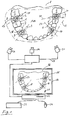
- the Fig. 1 shows a sketch to illustrate the method for measuring a dental situation 1 comprising a plurality of implants 2, 3, 4 and 5 for the insertion of dental restorations.
- a residual dentition 6 comprises a plurality of adjacent teeth 7.
- the first implant 2 is provided with a first measuring body 8
- the second implant 3 is with a second measuring body 9
- the third implant 4 is with a third measuring body 10
- the fourth implant 5 is with a fourth Measuring body 11 connected.
- the measuring bodies 8, 9, 10 and 11 have a measuring geometry 12, consisting of three points, which enables the determination of the position and the orientation of the implants 2, 3, 4 and 5 relative to the teeth 7 and relative to one another Process step, a first region 13, which is represented by a dashed line, measured by means of a first camera 14 using a first measurement method.
- a first region 13 which is represented by a dashed line
- the first measuring method may be based on a fringe projection method, a confocal microscopy method, a white-light interferometry method, a color pattern triangulation method, or a three-dimensional X-ray method.
- the overview image 15 is displayed by means of a display device 16, such as a monitor.
- the object areas 17, 18, 19 and 20 around the implants 2, 3, 4 and 5 are set.
- the object areas can either be determined manually by the user by means of a mouse pointer 21 or automatically.
- the object areas 17, 18, 19 and 20 are shown by a dashed line and are formed in a circle with a center coinciding with an axis of symmetry 25, 26, 27 and 28 of the implants 2, 3, 4 and 5.
- the defined object areas 17, 18, 19 and 20 are detected by means of a multi-camera system 29, consisting of a first camera 30 and a second camera 31.
- second measurement data are generated which are more precise than the first measurement data of the overview recording 15.
- the second measurement data have a higher resolution than the first measurement data and thus allow a more accurate determination of the position and orientation of the implants 2, 3, 4 and 5.
- the first measurement data of the overview image 15 and the second measurement data of the specified object regions are combined to form a superposed image 32, which is displayed by the display device 16.
- the user can quickly orient himself and determine the position and orientation of the implants 2, 3, 4 and 5 on the basis of the object areas 17, 18, 19 and 20.
- the determination of the position and orientation of the implants 2, 3, 4 and 5 can also be carried out automatically by means of a computer algorithm, with the measuring bodies 8, 9, 10 and 11 being targeted.
- the result of the present method is thus the exact position and orientation of the implants 2, 3, 4 and 5 relative to each other and relative to the teeth 7.
- Das in Fig. 1 shown multi-camera system 29 is suitable for performing a photogrammetric method, wherein the object areas 17, 18, 19 and 20 in each of the individual images of the cameras 30th and 31, and then a three-dimensional image of the object regions 17, 18, 19 and 20 is reconstructed from the second measurement data of these specified object regions.
- the Fig. 2 shows a sketch to illustrate an automatic definition of the object area 17 between the adjacent teeth 7, wherein the edge of the object area 17 is automatically set as a circle with a certain distance 40 and the axis of symmetry 25 of the implant 2.
- the distance may be, for example, between 4 mm and 10 mm.
- the position of the axis of symmetry 25 can be determined automatically by means of the measuring geometry 12 of the measuring body 8.
Description
Die Erfindung betrifft ein Verfahren zur Vermessung einer Zahnsituation umfassend mehrere Implantate und/oder Präparationen zum Einsetzen von Zahnrestaurationen. Unter Verwendung eines ersten Messverfahrens wird zunächst ein erster Bereich der Zahnsituation erfasst. Dabei werden erste Messdaten erzeugt. Der erste Bereich umfasst mindestens zwei Implantate und/oder Präparationen.The invention relates to a method for measuring a tooth situation comprising a plurality of implants and / or preparations for inserting dental restorations. Using a first measuring method, first a first area of the tooth situation is detected. The first measurement data is generated. The first area comprises at least two implants and / or preparations.
Aus dem Stand der Technik sind mehrere Verfahren zur Vermessung von Zahnsituationen bekannt, bei denen die relative Position von Implantaten oder Präparationen zueinander bestimmt wird.Several methods for the measurement of dental situations are known from the prior art, in which the relative position of implants or preparations to each other is determined.
Typischerweise erfolgt die Vermessung von Implantatpositionen und Implantatorientierungen mittels eines konventionellen Abdrucks, wobei ein Gipsmodell erstellt wird. Das Gipsmodell wird anschließend vermessen und die Positionen und Orientierungen der Implantate werden unter Verwendung der erzeugten Messdaten bestimmt. Bei diesen Verfahren wird meist die relative Lage und Orientierung der Implantate zueinander und relativ zum Restzahnbestand bestimmt.Typically, the measurement of implant positions and implant orientations by means of a conventional impression, wherein a plaster model is created. The gypsum model is then measured and the positions and orientations of the implants are determined using the generated measurement data. In these methods, the relative position and orientation of the implants to each other and relative to the remaining dentition is usually determined.
Bei einem alternativen Verfahren kann die Zahnsituation mittels eines optischen dreidimensionalen Messverfahrens vermessen werden, um anschließend digital die Lage und Orientierung der Implantate relativ zueinander und relativ zum Restzahnbestand zu bestimmen.In an alternative method, the tooth situation can be measured by means of an optical three-dimensional measuring method, in order subsequently to digitally determine the position and orientation of the implants relative to one another and relative to the remaining dentition.
Die
Die
Die
Ein sekundäres Duplikat wird in mehrere Duplikatsabschnitte zertrennt wobei die einzelnen Duplikatsabschnitte einzeln vermessen werden und die dabei ermittelten Daten gespeichert werden, wobei die Daten des Duplikats und die Daten der Duplikatsabschnitte zusammengeführt werden können. Darüber hinaus ist offenbart, dass die Ermittlung der Form des Duplikats mit einer geringeren Genauigkeit erfolgt als die Ermittlung der Form der Duplikatsabschnitte.
Ein Nachteil der genannten Verfahren besteht darin, dass die Qualität der Aufnahmen zur Bestimmung der Lage und Orientierung der Implantate relativ zueinander oft nicht ausreichend ist. Zugleich ist eine Aufnahme mit einer höheren Auflösung wegen einer damit verbundenen längeren Aufnahmezeit oft nicht möglich.A disadvantage of the mentioned methods is that the quality of the recordings for determining the position and orientation of the implants relative to one another is often insufficient. At the same time a recording with a higher resolution is often not possible because of a longer recording time associated with it.
Die Aufgabe der folgenden Erfindung besteht also darin, ein Verfahren zur Vermessung einer Zahnsituation bereitzustellen, das eine genaue Bestimmung der Lage und Orientierung von Implantaten relativ zueinander ermöglicht.The object of the following invention is therefore to provide a method for measuring a dental situation, which allows an accurate determination of the position and orientation of implants relative to each other.
Die Erfindung betrifft ein Verfahren zur Vermessung einer Zahnsituation umfassend mehrere Implantate und/oder Präparationen zum Einsetzen von Zahnrestaurationen. Unter Verwendung eines ersten Messverfahrens wird zunächst ein erster Bereich der Zahnsituation erfasst. Dabei werden erste Messdaten erzeugt. Der erste Bereich umfasst mindestens zwei Implantate und/oder Präparationen. Anschließend werden Objektbereiche um die Implantate und/oder die Präparationen festgelegt, wobei unter Verwendung eines zweiten Messverfahrens die festgelegten Objektbereiche erfasst werden. Dabei werden zweite Messdaten erzeugt, wobei das zweite Messverfahren präziser ist als das erste Messverfahren.The invention relates to a method for measuring a tooth situation comprising a plurality of implants and / or preparations for inserting dental restorations. Using a first measuring method, first a first area of the tooth situation is detected. The first measurement data is generated. The first area comprises at least two implants and / or preparations. Subsequently, object areas are defined around the implants and / or the preparations, wherein the defined object areas are detected using a second measuring method. In this case, second measured data are generated, with the second measuring method being more precise than the first measuring method.
Die ersten Messdaten und die zweiten Messdaten werden zu einer überlagerten Aufnahme der Zahnsituation zusammengefügt.The first measurement data and the second measurement data are combined to form a superimposed recording of the tooth situation.
Anhand der zweiten Messdaten der festgelegten Objektbereiche werden die Lage und die Orientierung der Implantate und/oder der Präparationen relativ zueinander und relativ zu den Zähnen ermittelt.Based on the second measurement data of the specified object areas, the position and orientation of the implants and / or the preparations relative to each other and relative to the teeth are determined.
Das Verfahren zur Vermessung der Zahnsituation kann sowohl auf eine Zahnsituation in der Mundhöhle des Patienten als auch auf ein Zahnmodell der Zahnsituation angewendet werden. Das Zahnmodell kann beispielsweise durch einen Gipsabdruck der Zahnsituation hergestellt sein. Die Implantate können beliebig gestaltet sein und eine bestimmte Anschlussgeometrie für ein einzusetzendes Abutment oder eine passende Zahnrestauration aufweisen. Zur Verbesserung der Vermessung können Messkörper verwendet werden, die mit den Implantaten verbunden werden. Die Messkörper können bestimmte Messgeometrien aufweisen, die eine Bestimmung der Lage und Orientierung der Implantate ermöglicht. Dabei kann die Messgeometrie eine bestimmte geometrische Form, wie ein Vieleck, oder beispielsweise drei in einem Dreieck angeordnete Punkte aufweisen. Die Messkörper können dabei so ausgestaltet sein, dass sie zur Vermessung mittels des ersten Messverfahrens und des zweiten Messverfahrens geeignet sind. Bei der Vermessung mittels eines Röntgenaufnahmeverfahrens können die Messkörper beispielsweise röntgensensitiv sein. Das vorliegende Verfahren kann auch zur Vermessung von Präparationen verwendet werden. Der erste Bereich kann einen Teil der Zahnsituation mit mindestens zwei Implantaten oder auch die gesamte Zahnsituation umfassen. Die erzeugten ersten Messdaten können dreidimensionale Bilddaten oder auch Rohdaten zur späteren Verarbeitung sein. Die Objektbereiche können beliebig geformt sein, beispielsweise können sie eine Kreisform um die Implantate aufweisen. Die zweiten Messdaten können dreidimensionale Bilddaten oder Rohdaten zur weiteren Verarbeitung sein. Die zweiten Messdaten sind präziser beispielsweise bezüglich der Auflösung und Genauigkeit im Vergleich zu den ersten Messdaten. Die Abweichung der zweiten Messdaten von den tatsächlichen Abmessungen des aufgenommenen Objekts ist also geringer als bei den ersten Messdaten.The method for measuring the dental situation can be applied both to a dental situation in the oral cavity of the patient and to a dental model of the dental situation. The tooth model can be produced for example by a plaster cast of the tooth situation. The implants can be of any desired design and have a specific connection geometry for an abutment to be inserted or a suitable dental restoration. To improve the measurement, measuring bodies can be used, which are connected to the implants. The measuring bodies can have certain measuring geometries, which allows a determination of the position and orientation of the implants. It can the measuring geometry has a certain geometric shape, such as a polygon, or, for example, three points arranged in a triangle. The measuring bodies can be designed so that they are suitable for measuring by means of the first measuring method and the second measuring method. When measuring by means of an X-ray recording method, the measuring bodies can be, for example, X-ray sensitive. The present method can also be used to measure preparations. The first region may comprise a part of the tooth situation with at least two implants or also the entire tooth situation. The generated first measurement data can be three-dimensional image data or also raw data for later processing. The object areas can be shaped as desired, for example, they can have a circular shape around the implants. The second measurement data may be three-dimensional image data or raw data for further processing. The second measurement data is more precise, for example, in terms of resolution and accuracy compared to the first measurement data. The deviation of the second measurement data from the actual dimensions of the recorded object is thus lower than in the first measurement data.
Das Zusammenfügen der ersten Messdaten und der zweiten Messdaten zu der überlagerten Aufnahme kann mittels eines Mustererkennungsalgorithmus erfolgen, der übereinstimmende Bereiche erkennt. Die überlagerte Aufnahme ermöglicht dem Benutzer einen schnellen Überblick über die gesamte Zahnsituation mit den integrierten präziseren zweiten Messdaten der Objektbereiche um die Implantate.The joining of the first measurement data and the second measurement data to the superimposed recording can be done by means of a pattern recognition algorithm that recognizes coincident areas. The superimposed recording allows the user a quick overview of the entire dental situation with the integrated more precise second measurement data of the object areas around the implants.
Zur Verbesserung der Vermessung können Messkörper auf die Implantate aufgesetzt werden, die eine Bestimmung der Lage und der Orientierung der Implantate erleichtern. Die Messkörper oder die sichtbaren Bereiche der eingesetzten Implantate können beispielsweise mittels eines Computeralgorithmus in den zweiten Messdaten erkannt werden, wobei anschließend die Lage und die Orientierung der Implantate relativ zueinander und relativ zu den Zähnen ebenfalls mittels eines Computeralgorithmus automatisch ermittelt werden können.To improve the measurement, measuring bodies can be placed on the implants, which facilitate a determination of the position and the orientation of the implants. The measuring bodies or the visible regions of the implants used can be detected, for example by means of a computer algorithm in the second measurement data, wherein subsequently the position and orientation of the implants relative to each other and relative to the teeth can also be determined automatically by means of a computer algorithm.
Ein Vorteil dieses Verfahrens liegt darin, dass zunächst eine Übersichtsaufnahme mittels des ersten Messverfahrens und anschließend eine präzisere Aufnahme mittels des zweiten Messverfahrens erzeugt werden. Dies ermöglicht eine genauere Vermessung der Implantate zur Bestimmung der Lage und Orientierung der Implantate relativ zueinander und relativ zur Zahnsituation, wobei die Vermessungsdauer verkürzt wird.One advantage of this method is that initially an overview image is generated by means of the first measurement method and subsequently a more precise image is recorded by means of the second measurement method. This allows a more accurate measurement of the implants to determine the position and orientation of the implants relative to each other and relative to the dental situation, the measurement time is shortened.
Vorteilhafterweise können die Objektbereiche manuell durch einen Benutzer festgelegt werden.Advantageously, the object areas can be defined manually by a user.
Bei der manuellen Festlegung der Objektbereiche kann der Benutzer mittels eines Computers die Objektbereiche mit einem Mauszeiger umranden. Der Benutzer kann auch ein virtuelles Werkzeug benutzen, wobei zunächst ein Mittelpunkt eines kreisförmigen Objektbereichs an eine Symmetrieachse eines Implantats festgelegt wird und anschließend ein Kreis um diesen Punkt mit einem passenden Abstand gezogen wird.When manually defining the object areas, the user can use a computer to surround the object areas with a mouse pointer. The user may also use a virtual tool, first defining a center of a circular object area on an axis of symmetry of an implant, and then drawing a circle around that point at an appropriate distance.
Vorteilhafterweise können die Objektbereiche automatisch mittels eines Suchalgorithmus festgelegt werden.Advantageously, the object areas can be determined automatically by means of a search algorithm.
Bei der automatischen Festlegung der Objektbereiche können die Implantate mittels des Suchalgorithmus computergestützt erkannt werden. Anschließend kann automatisch ein kreisförmiger Objektbereich um jeden der erkannten Implantate mit einem bestimmten Abstand zur Symmetrieachse des Implantats festgelegt werden. Der Abstand zum Mittelpunkt kann beispielsweise 2 mm bis 10 mm betragen.In the automatic definition of the object areas, the implants can be detected computer-assisted by means of the search algorithm. Subsequently, a circular object area around each of the detected implants can be automatically positioned at a certain distance from the symmetry axis of the implant be determined. The distance to the center may be, for example, 2 mm to 10 mm.
Vorteilhafterweise kann das erste Messverfahren auf einem Streifenprojektionsverfahren, auf einem konfokalen Mikroskopieverfahren, auf einem Weißlichtinterferometrieverfahren, auf einem Triangulationsverfahren mit farblichen Mustern oder auf einem dreidimensionalen Röntgenaufnahmeverfahren beruhen.Advantageously, the first measuring method can be based on a fringe projection method, on a confocal microscopy method, on a white-light interferometric method, on a triangulation method with colored patterns or on a three-dimensional X-ray recording method.
Bei dem bekannten Streifenprojektionsverfahren wird das Messobjekt mit einem Streifenmuster aus parallelen hellen und dunklen Streifen unterschiedlicher Breite beleuchtet. In einem weiteren Schritt wird das projizierte Streifenmuster unter einem bekannten Blickwinkel zur Projektion mittels einer Kamera aufgenommen. Unter Verwendung eines sogenannten Phasenschiebeverfahrens kann eine Projektionskoordinate bestimmt werden, die die Nummer des Streifens wiedergibt. Die Nummer des Streifens im Projektor entspricht einer Bildkoordinate in der Kamera. Bei einer bekannten Kameraposition und einer bekannten Projektorposition relativ zum Objekt kann ein Schnittpunkt zwischen einer Ebene, die durch den jeweiligen Streifen definiert ist und einer Geraden, die durch die Koordinate in der Kamera definiert ist, berechnet werden. Für jeden der Messpunkte wird auf diese Weise die dreidimensionale Koordinate der Oberfläche bestimmt.In the known fringe projection method, the measurement object is illuminated with a stripe pattern of parallel light and dark stripes of different widths. In a further step, the projected fringe pattern is recorded under a known viewing angle for projection by means of a camera. Using a so-called phase shift method, a projection coordinate representing the number of the strip can be determined. The number of the strip in the projector corresponds to a picture coordinate in the camera. With a known camera position and a known projector position relative to the object, an intersection between a plane defined by the respective strip and a straight line defined by the coordinate in the camera can be calculated. For each of the measuring points, the three-dimensional coordinate of the surface is determined in this way.
Bei der Weißlichtinterferometrie wird ein Licht geringer Kohärenzlänge verwendet, sodass farbige Indifferenzen entstehen, wenn die Weglängen im Referenz- und Objektstrahl nahezu gleich sind. Beim Verändern der Weglänge wird das Interferenzmuster verändert, sodass anhand des Interferenzmusters der Abstand zur Oberfläche des Messobjekts bestimmt werden kann.In white-light interferometry, a light of short coherence length is used, so that colored indifferences arise when the path lengths in the reference and object beams are nearly equal. When changing the path length, the interference pattern is changed so that the distance to the surface of the measurement object can be determined on the basis of the interference pattern.
Bei dem dreidimensionalen konfokalen Mikroskopieverfahren wird die Oberfläche des dentalen Objekts schrittweise abgetastet, wobei eine Fokalebene schrittweise verschoben wird. Das Licht außerhalb der Fokalebene wird mittels einer Lochblende möglichst ausgeblendet. Aus den gemessenen Bilddaten der einzelnen Schritte unterschiedlicher Fokalebenen kann anschließend ein dreidimensionales Modell des vermessenen Objekts berechnet werden.In the three-dimensional confocal microscopy method, the surface of the dental object is scanned stepwise, whereby a focal plane is shifted stepwise. The light outside the focal plane is suppressed as much as possible by means of a pinhole. From the measured image data of the individual steps of different focal planes, a three-dimensional model of the measured object can then be calculated.
Bei dem Triangulationsverfahren mit farblichen Mustern können mehrere Lichtquellen unterschiedlicher Farbe oder eine Lichtquelle mit mehreren Filtern unterschiedlicher Farbe und ein Projektionsgitter zur Erzeugung der projizierten farblichen Muster verwendet werden. Dadurch können klar von einander abgegrenzte farbliche Muster, wie parallele Linien unterschiedlicher Farbe, erzeugt werden, die auf das dentale Objekt projiziert werden. Dieses Verfahren kann als das erste Messverfahren zur Erzeugung der ersten Messdaten und/oder als das zweite Messverfahren zur Erzeugung der zweiten Messdaten verwendet werden.In the color pattern triangulation method, a plurality of different color light sources or a light source having a plurality of different color filters and a projection grating may be used to produce the projected color patterns. As a result, distinct color patterns, such as parallel lines of different colors, projected onto the dental object can be generated clearly. This method can be used as the first measurement method for generating the first measurement data and / or as the second measurement method for generating the second measurement data.
Das dreidimensionale Röntgenaufnahmeverfahren kann beispielsweise ein DVT- oder CT-Verfahren sein. Das erste Messverfahren oder das zweite Messverfahren kann auch ein MRT-Verfahren sein.The three-dimensional x-ray recording method may be, for example, a DVT or CT method. The first measurement method or the second measurement method may also be an MRI method.
Vorteilhafterweise kann das zweite, präzisere Messverfahren auf einem Triangulationsverfahren und auf einem Streifenprojektionsverfahren beruhen, wobei zuvor zumindest an den aufzunehmenden Objektbereichen eine Puderung erfolgt.Advantageously, the second, more precise measuring method can be based on a triangulation method and on a fringe projection method, wherein powdering takes place beforehand at least on the object areas to be recorded.
Für eine präzise Aufnahme ist eine nicht spiegelnde Oberfläche des vermessenen Objekts zwingend erforderlich. Dafür wird das dentale Objekt meist vor der Aufnahme mit einem speziellen Puder beschichtet. Nach der Aufnahme wird die aufgetragene Puderschicht entfernt. Bei einer fehlenden Puderung wird lediglich eine geringe Genauigkeit erreicht, da Aufnahmefehler durch ungleichmäßige Reflexionen erzeugt werden.For a precise image, a non-reflective surface of the measured object is absolutely necessary. For this, the dental object is usually coated with a special powder before taking it. After taking the applied powder layer is removed. In case of missing powdering Only a low accuracy is achieved because recording errors are generated by uneven reflections.
Vorteilhafterweise kann das zweite, präzisere Messverfahren auf einem Triangulationsverfahren beruhen, bei dem ein zweiter Triangulationswinkel geringer als ein erster Triangulationswinkel des ersten Messverfahrens sein kann und so klein gewählt ist, dass die Genauigkeitsanforderungen an die zweiten Messdaten erfüllt sind.Advantageously, the second, more precise measuring method can be based on a triangulation method, in which a second triangulation angle can be less than a first triangulation angle of the first measuring method and is chosen to be small enough that the accuracy requirements for the second measured data are met.
Der zweite Triangulationswinkel des zweiten präziseren Messverfahrens ist so klein gewählt, dass die Genauigkeitsanforderungen, wie beispielsweise eine ausreichende Auflösung, erfüllt sind.The second triangulation angle of the second more precise measuring method is chosen to be so small that the accuracy requirements, such as a sufficient resolution, are satisfied.
Vorteilhafterweise kann das zweite, präzisere Messverfahren mittels eines Multikamera-Systems durchgeführt werden und auf einem Photogrammetrieverfahren beruhen.Advantageously, the second, more precise measuring method can be carried out by means of a multi-camera system and be based on a photogrammetric method.
Das Photogrammetrieverfahren ist eine Messmethode und Auswerteverfahren der Fernerkundung, um aus Aufnahmen und genauen Messbildern eines Objektes aus unterschiedlichen Raumrichtungen seine räumliche Lage oder dreidimensionale Form zu bestimmen. Im Regelfall werden die Bilder mit einem speziellen Multikamera-System aufgenommen. Mittels dieses Verfahrens kann aus den zweidimensionalen optischen Aufnahmen der einzelnen Kameras des Multikamera-Systems eine dreidimensionale Aufnahme des aufzunehmenden Objekts berechnet werden.The photogrammetric method is a measurement method and evaluation method of remote sensing in order to determine its spatial position or three-dimensional shape from images and accurate measurement images of an object from different spatial directions. As a rule, the pictures are taken with a special multi-camera system. By means of this method, a three-dimensional image of the object to be recorded can be calculated from the two-dimensional optical images of the individual cameras of the multi-camera system.
Vorteilhafterweise kann das zweite, präzisere Messverfahren mittels eines taktilen Tastscanners durch eine punktweise Abtastung der Objektbereiche durchgeführt werden.Advantageously, the second, more precise measuring method can be carried out by means of a tactile touch scanner by a point-by-point scanning of the object areas.
Der taktile Tastscanner kann eine Vorrichtung sein, die die Objektbereiche Punkt für Punkt abtastet und für jeden Objektpunkt eine Tiefenkoordinate erzeugt wird. Aus den ermittelten Tiefenkoordinaten kann dann eine dreidimensionale Oberfläche des zu vermessenden Objekts erzeugt werden.The tactile touch scanner can be a device that scans the object areas point by point and for each object point a depth coordinate is generated. From the determined depth coordinates, a three-dimensional surface of the object to be measured can then be generated.
Vorteilhafterweise kann das zweite, präzisere Messverfahren auf einem dreidimensionalen Röntgenaufnahmeverfahren mit einer höheren Auflösung als beim ersten Messverfahren beruhen.Advantageously, the second, more precise measuring method can be based on a three-dimensional X-ray recording method with a higher resolution than in the first measuring method.
Bei einem DVT- oder CT-Verfahren kann die Auflösung des erzeugten dreidimensionalen Röntgenbildes durch eine Verminderung der Schnittfolge erzielt werden, die mit einer erhöhten Dosisbelastung verbunden ist.In a DVT or CT method, the resolution of the generated three-dimensional X-ray image can be achieved by a reduction of the cutting sequence, which is associated with an increased dose burden.
Vorteilhafterweise kann das zweite, präzisere Messverfahren mittels eines Multikamera-Systems durchgeführt werden und auf einem Photogrammetrieverfahren beruhen, wobei die Objektbereiche in jeder der einzelnen Aufnahmen des Multikamera-Systems festgelegt werden können. Anschließend kann anhand der zweiten Messdaten der Objektbereiche aus den einzelnen Aufnahmen eine dreidimensionale Aufnahme der Objektbereiche mittels eines Computeralgorithmus rekonstruiert werden.Advantageously, the second, more precise measuring method can be carried out by means of a multi-camera system and be based on a photogrammetric method, wherein the object areas can be defined in each of the individual recordings of the multi-camera system. Subsequently, based on the second measurement data of the object regions from the individual recordings, a three-dimensional recording of the object regions can be reconstructed by means of a computer algorithm.
Dadurch werden lediglich die Objektbereiche zur Rekonstruktion der dreidimensionalen Aufnahme verwendet. Dies führt zu einer kürzeren Rechenzeit bei der Rekonstruktion der dreidimensionalen Aufnahme.As a result, only the object areas are used to reconstruct the three-dimensional image. This leads to a shorter computing time in the reconstruction of the three-dimensional recording.
Die Erfindung wird anhand der Zeichnungen erläutert. Es zeigt, die
- Fig. 1
- eine Skizze der Zahnsituation zur Verdeutlichung des Verfahrens;
- Fig. 2
- eine Skizze zur Verdeutlichung der automatischen Festlegung eines Objektbereichs.
- Fig. 1
- a sketch of the tooth situation to clarify the procedure;
- Fig. 2
- a sketch to clarify the automatic definition of an object area.
Die
Die
- 11
- Zahnsituationdentition
- 22
- Implantatimplant
- 33
- Implantatimplant
- 44
- Implantatimplant
- 55
- Implantatimplant
- 66
- RestzahnbestandDentition
- 77
- Zähneteeth
- 88th
- Messkörpermeasuring body
- 99
- Messkörpermeasuring body
- 1010
- Messkörpermeasuring body
- 1111
- Messkörpermeasuring body
- 1212
- Messgeometriemeasurement geometry
- 1313
- BereichArea
- 1414
- Kameracamera
- 1515
- ÜbersichtsaufnahmeOverview image
- 1616
- Anzeigevorrichtungdisplay device
- 1717
- ObjektbereichProperty area
- 1818
- ObjektbereichProperty area
- 1919
- ObjektbereichProperty area
- 2020
- ObjektbereichProperty area
- 2121
- Mauszeigercursor
- 2222
- Computercomputer
- 2323
- Tastaturkeyboard
- 2424
- Mausmouse
- 2525
- Symmetrieachseaxis of symmetry
- 2626
- Symmetrieachseaxis of symmetry
- 2727
- Symmetrieachseaxis of symmetry
- 2828
- Symmetrieachseaxis of symmetry
- 2929
- Multikamera-SystemMulti-camera system
- 3030
- erste Kamerafirst camera
- 3131
- zweite Kamerasecond camera
- 3232
- gesamte Aufnahmeentire recording
- 4040
- Abstand/ RadiusDistance / radius
Claims (10)
- A method for measuring a dental condition (1) comprising several implants (2, 3, 4, 5) and/or preparations for attaching dental restorations, wherein, using a first measuring method, a first region (13) of the dental condition (1) is detected and therewith first measured data generated, wherein the first region (13) comprises at least two implants (2, 3, 4, 5) and/or preparations, wherein object areas (17, 18, 19, 20) around the implants (2, 3, 4, 5) and/or the preparations are determined, wherein, using a second measuring method, the determined object areas (17, 18, 29, 20) are detected and therewith second measured data generated, wherein the second measuring method is more precise than the first measuring method, wherein the first measured data and the second measured data are combined into one overlaid image (32) of the dental condition (1), characterized in that the position and orientation of the implants (2, 3, 4, 5) and/or the preparations relative to each other and relative to the teeth (7) are determined based upon the second measured data of the determined object areas (17, 18, 19, 20).
- The method according to claim 1, characterized in that the object areas (17, 18, 19, 20) are determined by a user manually.
- The method according to claim 1, characterized in that the object areas (17, 18, 19, 20) are determined automatically by means of a search algorithm.
- The method according to one of claims 1 through 3, characterized in that the first measuring method is based upon a fringe projection method, upon a confocal microscopy method, upon a white light interferometry method, upon a triangulation method with colored patterns, or upon a three-dimensional radiography method.
- The method according to one of claims 1 through 4, characterized in that the second, more precise measuring method is based upon a triangulation method and upon a fringe projection method, wherein a powdering of at least the object areas (17, 18, 19, 20) to be acquired takes place beforehand.
- The method according to claim 4 or 5, characterized in that the second, more precise measuring method is based upon a triangulation method, in which a second triangulation angle is less than a first triangulation angle of the first measuring method and is selected to be so small that the precision requirements for the second measured data are met.
- The method according to one of claims 1 through 4, characterized in that the second, more precise measuring method is carried out by means of a multi-camera system (29) and is based upon a photogrammetry method.
- The method according to one of claims 1 through 4, characterized in that the second, more precise measuring method is carried out by means of a tactile scanner by scanning the object areas point by point.
- The method according to one of claims 1 through 4, characterized in that the second, more precise measuring method is based upon a three-dimensional radiography method with a higher resolution than in the first measuring method.
- The method according to one of claims 1 through 6, characterized in that the second, more precise measuring method is carried out by means of a multi-camera system (29) and is based upon a photogrammetry method, wherein the object areas (17, 18, 19, 20) are determined in each of the individual images of the multi-camera system (29) and, subsequently, based upon the second measured data of the object areas (17, 18, 19, 20) from the individual images, a three-dimensional image of the object areas (17, 18, 19, 20) is reconstructed using a computer algorithm.
Applications Claiming Priority (2)
| Application Number | Priority Date | Filing Date | Title |
|---|---|---|---|
| DE102012207499A DE102012207499B3 (en) | 2012-05-07 | 2012-05-07 | Method for measuring a dental situation |
| PCT/EP2013/059426 WO2013167555A1 (en) | 2012-05-07 | 2013-05-07 | Method for measuring a dental situation |
Publications (2)
| Publication Number | Publication Date |
|---|---|
| EP2846729A1 EP2846729A1 (en) | 2015-03-18 |
| EP2846729B1 true EP2846729B1 (en) | 2016-07-20 |
Family
ID=48570065
Family Applications (1)
| Application Number | Title | Priority Date | Filing Date |
|---|---|---|---|
| EP13726439.6A Active EP2846729B1 (en) | 2012-05-07 | 2013-05-07 | Method for measuring a dental situation |
Country Status (5)
| Country | Link |
|---|---|
| US (1) | US10080636B2 (en) |
| EP (1) | EP2846729B1 (en) |
| JP (1) | JP6293122B2 (en) |
| DE (1) | DE102012207499B3 (en) |
| WO (1) | WO2013167555A1 (en) |
Families Citing this family (6)
| Publication number | Priority date | Publication date | Assignee | Title |
|---|---|---|---|---|
| WO2017111116A1 (en) | 2015-12-24 | 2017-06-29 | 株式会社モリタ製作所 | Three-dimensional-measurement method, and three-dimensional-measurement device |
| KR102482062B1 (en) | 2016-02-05 | 2022-12-28 | 주식회사바텍 | Dental three-dimensional scanner using color pattern |
| DE102016004641A1 (en) * | 2016-04-20 | 2017-10-26 | Axel Scheffer | Method and system for detecting the alignment of at least one drill sleeve in a drilling template produced for the correct position implantation of dental implants |
| DE102016213399A1 (en) * | 2016-07-21 | 2018-01-25 | Sirona Dental Systems Gmbh | Surveying system and method for measuring an implant-implant situation |
| JP2019524327A (en) * | 2016-08-10 | 2019-09-05 | ケアストリーム・デンタル・テクノロジー・トプコ・リミテッド | Automatic intraoral 3D scanner with low coherence range |
| JP7267974B2 (en) | 2020-07-01 | 2023-05-02 | 株式会社モリタ製作所 | IDENTIFICATION DEVICE, SCANNER SYSTEM, IDENTIFICATION METHOD, AND IDENTIFICATION PROGRAM |
Citations (2)
| Publication number | Priority date | Publication date | Assignee | Title |
|---|---|---|---|---|
| US20080038688A1 (en) * | 2005-03-03 | 2008-02-14 | Cadent Ltd. | System and method for scanning an intraoral cavity |
| DE102008006048A1 (en) * | 2008-01-25 | 2009-07-30 | Straumann Holding Ag | Method for modeling an individual denture |
Family Cites Families (33)
| Publication number | Priority date | Publication date | Assignee | Title |
|---|---|---|---|---|
| CH672722A5 (en) * | 1986-06-24 | 1989-12-29 | Marco Brandestini | |
| US5372502A (en) * | 1988-09-02 | 1994-12-13 | Kaltenbach & Voight Gmbh & Co. | Optical probe and method for the three-dimensional surveying of teeth |
| US5569578A (en) * | 1990-04-10 | 1996-10-29 | Mushabac; David R. | Method and apparatus for effecting change in shape of pre-existing object |
| FR2692773B3 (en) | 1992-06-26 | 1994-08-26 | Diret Francois | Correlation device for three-dimensional seizures of human organs. |
| JPH0824685B2 (en) * | 1992-11-25 | 1996-03-13 | 株式会社江川 | Implant structure measuring method and measuring apparatus |
| ATE234049T1 (en) | 1997-10-31 | 2003-03-15 | Dcs Forschungs & Entwicklungs | METHOD AND DEVICE FOR PRODUCING A DENTAL PROSTITUTION PART |
| US7234937B2 (en) | 1999-11-30 | 2007-06-26 | Orametrix, Inc. | Unified workstation for virtual craniofacial diagnosis, treatment planning and therapeutics |
| TW576729B (en) | 2003-06-12 | 2004-02-21 | Univ Nat Taipei Technology | Apparatus and technique for automatic 3-D dental data required for crown reconstruction |
| DE102004035091B4 (en) | 2004-07-20 | 2017-10-26 | Sirona Dental Systems Gmbh | Method for determining the position and orientation of the axis of a dental implant located directly in the patient's mouth and attachment therefor |
| DE102004035090A1 (en) | 2004-07-20 | 2006-02-16 | Sirona Dental Systems Gmbh | Compensation part and method for the measurement of dental restorations |
| DE102004051165B3 (en) | 2004-10-20 | 2006-06-08 | Willytec Gmbh | Method and device for generating data sets for the production of dental prostheses |
| ES2297586T3 (en) | 2005-08-24 | 2008-05-01 | Degudent Gmbh | PROCEDURE AND DEVICE TO DETECT THE FORM OF A DENTAL TECHNICAL OBJECT. |
| CA2556533A1 (en) | 2005-08-24 | 2007-02-24 | Degudent Gmbh | Method of determining the shape of a dental technology object and apparatus performing the method |
| US7912257B2 (en) | 2006-01-20 | 2011-03-22 | 3M Innovative Properties Company | Real time display of acquired 3D dental data |
| JP2007209575A (en) * | 2006-02-10 | 2007-08-23 | Shimadzu Corp | Method of manufacturing dental prosthesis and dental prosthesis designing device |
| EP1820469B1 (en) | 2006-02-16 | 2009-10-14 | Institut Straumann AG | Method for scanning a tooth model |
| EP1820470B2 (en) | 2006-02-16 | 2012-06-13 | Institut Straumann AG | Device for scanning a tooth model |
| DE102006049695A1 (en) | 2006-10-16 | 2008-04-24 | Fraunhofer-Gesellschaft zur Förderung der angewandten Forschung e.V. | Device and method for contactless detection of a three-dimensional contour |
| US7978892B2 (en) | 2006-10-25 | 2011-07-12 | D4D Technologies, Llc | 3D photogrammetry using projected patterns |
| EP3085330B1 (en) * | 2006-10-27 | 2018-06-13 | Nobel Biocare Services AG | Method and apparatus for obtaining data for a dental component and a physical dental model |
| US10206757B2 (en) | 2007-01-10 | 2019-02-19 | Nobel Biocare Services Ag | Method and system for dental planning and production |
| DE102007005726B4 (en) * | 2007-01-31 | 2010-05-12 | Sirona Dental Systems Gmbh | Device and method for 3D optical measurement |
| DE102007056820A1 (en) * | 2007-11-23 | 2009-06-18 | Sirona Dental Systems Gmbh | Measuring body for an implant and method for creating a 3D measurement recording |
| DE102008054985B4 (en) * | 2008-12-19 | 2012-02-02 | Sirona Dental Systems Gmbh | Method and device for optical measurement of three-dimensional objects by means of a dental 3D camera using a triangulation method |
| DE102008055158B4 (en) * | 2008-12-24 | 2011-12-22 | Sirona Dental Systems Gmbh | Method for 3D measurement of the surface of an object, in particular for dental purposes |
| DE102009001086B4 (en) * | 2009-02-23 | 2014-03-27 | Sirona Dental Systems Gmbh | Hand-held dental camera and method for 3D optical measurement |
| US20100268069A1 (en) * | 2009-04-16 | 2010-10-21 | Rongguang Liang | Dental surface imaging using polarized fringe projection |
| US8570530B2 (en) * | 2009-06-03 | 2013-10-29 | Carestream Health, Inc. | Apparatus for dental surface shape and shade imaging |
| DE102009038588A1 (en) | 2009-08-26 | 2011-03-24 | Degudent Gmbh | Method for determining a complete data record of an object to be measured |
| EP4029471B1 (en) | 2010-07-12 | 2023-11-22 | 3Shape A/S | 3d modeling of an object using textural features |
| DE102011077564B4 (en) * | 2011-06-15 | 2016-08-25 | Sirona Dental Systems Gmbh | Method for the optical three-dimensional measurement of a dental object |
| FR2977469B1 (en) | 2011-07-08 | 2013-08-02 | Francois Duret | THREE-DIMENSIONAL MEASURING DEVICE USED IN THE DENTAL FIELD |
| US20140253686A1 (en) * | 2013-03-08 | 2014-09-11 | Victor C. Wong | Color 3-d image capture with monochrome image sensor |
-
2012
- 2012-05-07 DE DE102012207499A patent/DE102012207499B3/en not_active Withdrawn - After Issue
-
2013
- 2013-05-07 EP EP13726439.6A patent/EP2846729B1/en active Active
- 2013-05-07 JP JP2015510777A patent/JP6293122B2/en active Active
- 2013-05-07 US US14/399,271 patent/US10080636B2/en active Active
- 2013-05-07 WO PCT/EP2013/059426 patent/WO2013167555A1/en active Application Filing
Patent Citations (2)
| Publication number | Priority date | Publication date | Assignee | Title |
|---|---|---|---|---|
| US20080038688A1 (en) * | 2005-03-03 | 2008-02-14 | Cadent Ltd. | System and method for scanning an intraoral cavity |
| DE102008006048A1 (en) * | 2008-01-25 | 2009-07-30 | Straumann Holding Ag | Method for modeling an individual denture |
Also Published As
| Publication number | Publication date |
|---|---|
| JP6293122B2 (en) | 2018-03-14 |
| DE102012207499B3 (en) | 2013-09-05 |
| US20150072313A1 (en) | 2015-03-12 |
| WO2013167555A1 (en) | 2013-11-14 |
| EP2846729A1 (en) | 2015-03-18 |
| JP2015523108A (en) | 2015-08-13 |
| US10080636B2 (en) | 2018-09-25 |
Similar Documents
| Publication | Publication Date | Title |
|---|---|---|
| EP1903979B1 (en) | Method and device for producing dental prosthesis elements | |
| EP2846729B1 (en) | Method for measuring a dental situation | |
| EP0299490B2 (en) | Method for producing dental prosthesis | |
| EP2212646B1 (en) | Method for optical measurement of objects using a triangulation method | |
| DE102011077564B4 (en) | Method for the optical three-dimensional measurement of a dental object | |
| EP1181814B1 (en) | Method for detecting and representing one or more objects, for example teeth | |
| DE60218386T2 (en) | Method and system for creating a dental model by means of imaging | |
| DE19838238A1 (en) | Process for the computer-controlled manufacture of dentures | |
| EP3487443B1 (en) | Method for measuring an implant-implant situation | |
| DE102012210758A1 (en) | Method for checking tooth positions | |
| DE102012214470B4 (en) | Method for registering individual three-dimensional optical images to form an overall image of a tooth situation | |
| WO2014139944A1 (en) | Method for superimposing digitalized depictions and reference marker device | |
| EP0447531B1 (en) | Process and device for the three-dimensional optical measurement, especially of teeth in patients' buccal cavities | |
| DE102015225130A1 (en) | Method for calibrating an X-ray image | |
| DE102012104373A1 (en) | Method for simulating motion of e.g. upper jaw, for optimizing tooth restorations of male patient in clinic, involves directly determining movement parameters of upper jaw and/or lower jaw from measurement records of upper and lower jaws | |
| EP3984495A1 (en) | Method for forming a dental restoration | |
| EP3636202B1 (en) | Dental guiding system for dental preparation | |
| DE19619951A1 (en) | Generation of three dimensional images of human teeth | |
| DE102015104560A1 (en) | Method for operating a surgical microscope arrangement | |
| EP2394603A1 (en) | Method and data processing device for providing geometry data for dental and/or jaw areas | |
| DE102012205800A1 (en) | Device for combining surface model and volume model of objects e.g. human skull during orthodontic treatment, has model registrant that is provided to align models relative to each other, such that coverage measurement is maximized | |
| DE102022102335A1 (en) | Method and system for recording and displaying movements of the teeth and/or joints of the lower jaw |
Legal Events
| Date | Code | Title | Description |
|---|---|---|---|
| PUAI | Public reference made under article 153(3) epc to a published international application that has entered the european phase |
Free format text: ORIGINAL CODE: 0009012 |
|
| 17P | Request for examination filed |
Effective date: 20141120 |
|
| AK | Designated contracting states |
Kind code of ref document: A1 Designated state(s): AL AT BE BG CH CY CZ DE DK EE ES FI FR GB GR HR HU IE IS IT LI LT LU LV MC MK MT NL NO PL PT RO RS SE SI SK SM TR |
|
| AX | Request for extension of the european patent |
Extension state: BA ME |
|
| DAX | Request for extension of the european patent (deleted) | ||
| GRAP | Despatch of communication of intention to grant a patent |
Free format text: ORIGINAL CODE: EPIDOSNIGR1 |
|
| INTG | Intention to grant announced |
Effective date: 20160211 |
|
| RAP1 | Party data changed (applicant data changed or rights of an application transferred) |
Owner name: SIRONA DENTAL SYSTEMS GMBH |
|
| GRAS | Grant fee paid |
Free format text: ORIGINAL CODE: EPIDOSNIGR3 |
|
| GRAA | (expected) grant |
Free format text: ORIGINAL CODE: 0009210 |
|
| RBV | Designated contracting states (corrected) |
Designated state(s): AT CH DE FR GB IT LI |
|
| AK | Designated contracting states |
Kind code of ref document: B1 Designated state(s): AT CH DE FR GB IT LI |
|
| REG | Reference to a national code |
Ref country code: GB Ref legal event code: FG4D Free format text: NOT ENGLISH |
|
| REG | Reference to a national code |
Ref country code: CH Ref legal event code: EP |
|
| REG | Reference to a national code |
Ref country code: AT Ref legal event code: REF Ref document number: 813382 Country of ref document: AT Kind code of ref document: T Effective date: 20160815 |
|
| REG | Reference to a national code |
Ref country code: DE Ref legal event code: R096 Ref document number: 502013003807 Country of ref document: DE |
|
| REG | Reference to a national code |
Ref country code: DE Ref legal event code: R097 Ref document number: 502013003807 Country of ref document: DE |
|
| REG | Reference to a national code |
Ref country code: FR Ref legal event code: PLFP Year of fee payment: 5 |
|
| PLBE | No opposition filed within time limit |
Free format text: ORIGINAL CODE: 0009261 |
|
| STAA | Information on the status of an ep patent application or granted ep patent |
Free format text: STATUS: NO OPPOSITION FILED WITHIN TIME LIMIT |
|
| 26N | No opposition filed |
Effective date: 20170421 |
|
| REG | Reference to a national code |
Ref country code: FR Ref legal event code: PLFP Year of fee payment: 6 |
|
| REG | Reference to a national code |
Ref country code: DE Ref legal event code: R082 Ref document number: 502013003807 Country of ref document: DE |
|
| REG | Reference to a national code |
Ref country code: FR Ref legal event code: PLFP Year of fee payment: 11 |
|
| PGFP | Annual fee paid to national office [announced via postgrant information from national office to epo] |
Ref country code: GB Payment date: 20230330 Year of fee payment: 11 |
|
| P01 | Opt-out of the competence of the unified patent court (upc) registered |
Effective date: 20230509 |
|
| PGFP | Annual fee paid to national office [announced via postgrant information from national office to epo] |
Ref country code: IT Payment date: 20230412 Year of fee payment: 11 Ref country code: FR Payment date: 20230411 Year of fee payment: 11 Ref country code: DE Payment date: 20230331 Year of fee payment: 11 Ref country code: CH Payment date: 20230602 Year of fee payment: 11 |
|
| PGFP | Annual fee paid to national office [announced via postgrant information from national office to epo] |
Ref country code: AT Payment date: 20230425 Year of fee payment: 11 |