EP2845560A2 - Method of making indirect bonding transfer apparatus for orthodontic therapy - Google Patents
Method of making indirect bonding transfer apparatus for orthodontic therapy Download PDFInfo
- Publication number
- EP2845560A2 EP2845560A2 EP20140187971 EP14187971A EP2845560A2 EP 2845560 A2 EP2845560 A2 EP 2845560A2 EP 20140187971 EP20140187971 EP 20140187971 EP 14187971 A EP14187971 A EP 14187971A EP 2845560 A2 EP2845560 A2 EP 2845560A2
- Authority
- EP
- European Patent Office
- Prior art keywords
- replica
- orthodontic
- appliances
- appliance
- patient
- Prior art date
- Legal status (The legal status is an assumption and is not a legal conclusion. Google has not performed a legal analysis and makes no representation as to the accuracy of the status listed.)
- Granted
Links
Images


Classifications
-
- A—HUMAN NECESSITIES
- A61—MEDICAL OR VETERINARY SCIENCE; HYGIENE
- A61C—DENTISTRY; APPARATUS OR METHODS FOR ORAL OR DENTAL HYGIENE
- A61C7/00—Orthodontics, i.e. obtaining or maintaining the desired position of teeth, e.g. by straightening, evening, regulating, separating, or by correcting malocclusions
- A61C7/12—Brackets; Arch wires; Combinations thereof; Accessories therefor
- A61C7/14—Brackets; Fixing brackets to teeth
- A61C7/146—Positioning or placement of brackets; Tools therefor
-
- B—PERFORMING OPERATIONS; TRANSPORTING
- B33—ADDITIVE MANUFACTURING TECHNOLOGY
- B33Y—ADDITIVE MANUFACTURING, i.e. MANUFACTURING OF THREE-DIMENSIONAL [3-D] OBJECTS BY ADDITIVE DEPOSITION, ADDITIVE AGGLOMERATION OR ADDITIVE LAYERING, e.g. BY 3-D PRINTING, STEREOLITHOGRAPHY OR SELECTIVE LASER SINTERING
- B33Y80/00—Products made by additive manufacturing
Definitions
- This invention relates to method and apparatus for bonding orthodontic appliances such as brackets to a patient's teeth.
- the present invention also relates to methods for indirect bonding of orthodontic appliances.
- Orthodontic treatment involves movement of malpositioned teeth to desired locations in the oral cavity. Orthodontic treatment can improve the patient's facial appearance, especially in instances where the teeth are noticeably crooked or where the jaws are out of alignment with each other. Orthodontic treatment can also enhance the function of the teeth by providing better occlusion during mastication.
- brackets tiny, slotted appliances known as brackets.
- the brackets are fixed to the patient's teeth and an archwire is placed in the slot of each bracket.
- the archwire forms a track to guide movement of teeth to desired locations.
- brackets The ends of orthodontic archwires are often connected to small appliances known as buccal tubes that are, in turn, secured to the patient's molar teeth.
- a set of brackets, buccal tubes and an archwire is provided for each of the patient's upper and lower dental arches.
- the brackets, buccal tubes and archwires are commonly referred to collectively as "braces”.
- the precise position of the appliances on the teeth is an important factor for helping to ensure that the teeth move to their intended final positions.
- one common type of orthodontic treatment technique is known as the "straight-wire" technique, where the archwire lies in a horizontal plane at the conclusion of treatment. Consequently, if a bracket is attached to the tooth at a location that is too close to the occlusal or outer tip of the tooth, the orthodontist using a straight-wire technique will likely find that the tooth in its final position is unduly intruded. On the other hand, if the bracket is attached to the tooth at a location closer to the gingiva than is appropriate, it is likely that the final position of the tooth will be more extruded than desired.
- orthodontic appliances that are adapted to be adhesively bonded to the patient's teeth are placed and connected to the teeth by either one of two techniques: a direct bonding technique, or an indirect bonding technique.
- a direct bonding technique the appliance and adhesive are grasped with a pair of tweezers or other hand instrument and placed by the practitioner on the surface of the tooth in an approximate desired location.
- the appliance is shifted along the surface of the tooth as needed until the practitioner is satisfied with its position.
- the appliance is pressed firmly onto the tooth to seat the appliance in the adhesive. Excess adhesive in areas adjacent the base of the appliance is removed, and the adhesive is then allowed to cure and fix the appliance firmly in place.
- Another problem associated with the direct bonding technique described above concerns the significant length of time needed to carry out the procedure of bonding each appliance to each individual tooth.
- the practitioner will attempt to ensure that each appliance is positioned in its precise, intended location before the adhesive is cured, and some amount of time may be necessary before the practitioner is satisfied with the location of each appliance.
- the patient may experience discomfort during the procedure and have difficulty in remaining relatively motionless, especially if the patient is an adolescent.
- there are aspects of the direct bonding technique that can be considered a nuisance for both the practitioner and for the patient.
- Indirect bonding techniques avoid many of the problems noted above.
- indirect bonding techniques known in the past have involved the use of a placement device or transfer apparatus having a shape that matches the configuration of at least part of the patient's dental arch.
- One type of placement device or transfer apparatus is often called a "transfer tray" and typically has a cavity for receiving a number of teeth simultaneously.
- a set of appliances such as brackets are releasably connected to the tray at certain, predetermined locations.
- jigs Other types of transfer apparatus used in indirect bonding are often referred to as "jigs" and resemble a framework that contacts one or more teeth at certain locations.
- a jig constructed for use in bonding a single appliance to a single tooth may have an arm that extends over and contacts an incisal section of the tooth.
- An appliance such as a bracket is releasably connected to the jig at a certain, predetermined location relative to the tooth.
- an adhesive is typically applied to the base of each appliance by the orthodontist or a staff member.
- the device is then placed over the patient's teeth and remains in place until such time as the adhesive hardens.
- the apparatus is detached from the teeth as well as from the appliances, with the result that all of the appliances previously connected to the apparatus are now bonded to respective teeth at their intended, predetermined locations.
- one method of indirect bonding of orthodontic appliances using the transfer tray described above includes the steps of taking an impression of each of the patient's dental arches and then making a replica plaster or "stone" model from each impression. Next, the appliances are bonded to the stone models at desired locations.
- the bonding adhesive can be a chemical curing adhesive (such as Concise brand adhesive from 3M) or a light-curable adhesive (such as Transbond XT brand adhesive or Transbond LR brand adhesive from 3M).
- the brackets may be adhesive precoated brackets such as those described in U.S. Patent Nos. 5,015,180 , 5,172,809 , 5,354,199 and 5,429,229 .
- the transfer tray is then made by placing a matrix material over the model as well as over the appliances placed in the model.
- a plastic sheet matrix material may be held by a frame and exposed to radiant heat. Once the plastic sheet material has softened, it is placed over the model and the appliances. Air in the space between the sheet material and the model is then evacuated, and the plastic sheet material assumes a configuration that precisely matches the shape of the replica teeth of the stone model and attached appliances.
- the plastic sheet matrix material is then allowed to cool and harden to form a tray.
- the tray and the appliances (which are embedded in an interior wall of the tray) are then detached from the stone model. If the cured adhesive that was used to bond the appliances to the stone model remains on the base of the appliances after detachment from the stone model, the adhesive serves as a "custom" base having a concave contour that precisely replicates the convex contour of the previous attachment location of the stone model, as well as the convex configuration of the intended mounting location of the appliances on the patient's teeth.
- each appliance is ultimately positioned on the patient's teeth at precisely the same location that corresponds to the previous location of the same appliance on the stone model.
- Indirect bonding techniques offer a number of advantages over direct bonding techniques. For one thing, and as indicated above, it is possible to bond a plurality of appliances to a patient's dental arch simultaneously, thereby avoiding the need to bond each appliance in individual fashion.
- the transfer apparatus helps to locate the appliances in their proper, intended positions such that adjustment of each appliance on the surface of the tooth before bonding is avoided.
- the increased placement accuracy of the appliances that is often afforded by indirect bonding techniques helps ensure that the patient's teeth are moved to their proper, intended positions at the conclusion of treatment.
- U.S. Patent No. 5,971,754 describes a two-component indirect bonding adhesive with a relatively fast curing time that reduces the length of time that the tray must be firmly held against the patient's teeth.
- U.S. Patent No. 6,123,544 describes a transfer tray that receives movable arms for placing appliances on the patient's teeth once the tray is positioned in the oral cavity.
- the present invention is directed toward a method of constructing transfer apparatus for orthodontic indirect bonding, wherein a spacer material is applied to a replica of the patient's dentition.
- the spacer material has at least one cavity for receiving an orthodontic appliance, and remains on the replica while a tray is formed over the spacer material.
- the cavity is located in the spacer material at a certain, pre-selected position, with the result that the appliance is ultimately positioned in its proper, intended location with respect to the replica.
- the present invention in one aspect concerns a method of making transfer apparatus for orthodontic indirect bonding comprising:
- the present invention concerns an assembly for making transfer apparatus for use in indirect bonding of orthodontic appliances.
- the assembly comprises:
- the present invention concerns a method of making transfer apparatus for orthodontic indirect bonding that comprises:
- FIG. 1 illustrates a replica 20 of a portion of a dental arch of an orthodontic patient.
- the replica 20 represents the patient's lower dental arch.
- a replica of a patient's upper dental arch may be provided as an addition to or as an alternative to the lower dental arch replica as shown.
- the replica 20 may represent only a portion of a dental arch, such as a quadrant of an arch or only one or two teeth of a dental arch.
- the replica 20 includes a number of replica teeth 22, corresponding to each tooth of the patient's lower dental arch.
- the replica 20 is made by first taking an impression of the patient's lower dental arch, using care to avoid undue distortion.
- An alginate impression material may be used, such as "Palgat” Plus brand alginate impression material from 3M Espe.
- a hydrocolloid or vinyl polysiloxane impression material may be used, such as "Position Penta” brand vinyl polysiloxane impression material from 3M ESPE.
- the model or replica 20 is then made from the impression.
- the replica 20 is a "stone" model made from plaster of Paris, using care to avoid bubbles in the model. If small voids are present, the voids can be filled with a small, additional quantity of plaster of Paris.
- the replica 20 includes only the replica teeth 22 and sufficient replica gingival tissue 24 to hold the replica teeth 22 together.
- the replica 20 may be made using digital data that is representative of the patient's teeth and adjacent gingival tissue.
- the digital data may be obtained by use of a hand-held intra-oral scanner or other device known in the art.
- the digital data may be obtained by scanning an impression or a stone model.
- the replica 20 may then be made from the digital data using, for example, a stereo lithographic printer.
- the replica 20 may also be made using digital data in conjunction with a milling process.
- a CNC milling machine similar to the CAD/CIM milling machines sold by Cerec Network of Buelach, Switzerland, may be used to mill replicas made of ceramic, composite or other materials.
- An intra-oral camera similar to the cameras associated with the Cerec machines, may be used to obtain digital data representing the shape of the dental arches.
- a scanner may be used to scan an impression or a model of an impression to obtain the digital data.
- the replica 20 is an accurate representation of the patient's oral structure.
- the replica teeth 22 will have a configuration and orientation that are identical to the configuration and orientation of the corresponding teeth of the orthodontic patient.
- the replica gingival tissue 24 will have a shape that matches the shape of the corresponding portions of the gingival tissue of the patient.
- a thin layer of a release agent is then applied to the replica 20 and allowed to dry.
- a suitable release agent is a water soluble polyvinyl alcohol, such as "PA0810" from PTM & W Company of Santa Fe Springs, California.
- a spacer material 26 is applied to the replica 20.
- the spacer material 26 preferably comprises a custom-made material that is optionally formed using a rapid prototyping method. Examples of suitable rapid prototyping methods include stereolithography, thermojet printing and the like. Preferably, digital data representing the shape of a portion of the patient's dental arch is used in the rapid prototyping method to make the spacer material 26.
- the spacer material 26 includes a number of pockets or cavities 28, each of which has a shape adapted to complementally receive a corresponding orthodontic appliance 34.
- a corresponding orthodontic appliance 34 For example, if an orthodontic bracket is intended to be received in one of the cavities 28, such cavity 28 optionally has an occlusal wall portion, a mesial wall portion, a gingival wall portion, a distal wall portion and a facial wall portion that match the configuration of the occlusal side, the mesial side, the gingival side, the occlusal side and the facial side respectively of the bracket.
- the gingival wall portion may be omitted to facilitate subsequent removal of the transfer apparatus from the patient's dental arch.
- the cavities 28 include small protrusions that extend into and are complementally received in an archwire slot, a vertical slot between tiewings, and/or other features of the appliance.
- the cavities 28 are constructed slightly smaller than the corresponding appliance 34 in order to each firmly hold the orthodontic appliance 34 in place.
- the spacer material 26 is sufficiently flexible to enable the appliance 34 to be released from the cavity 28 when desired.
- Each of the cavities 28 is positioned in a location that corresponds to the subsequent desired location of an orthodontic appliance 34 on the dental arch.
- each of the cavities 28 may be positioned to place the center of the appliance 34 in a location corresponding to the facial axis point (or "FA" point) of the corresponding replica tooth 22, although other locations are also possible.
- the spacer material 26 functions to subsequently provide clearance in the transfer apparatus for receiving the orthodontic appliances 34.
- the locations of the cavities 28 and consequently the ultimate position of the placed appliance 34 are determined by computer software that has access to digital data representing a virtual model of the replica 20.
- the software preferably includes subprograms suitable to analyze the existing malocclusion of the patient and select proper appliances 34 for treatment of the particular malocclusion at hand.
- the software instructs automated apparatus (such as apparatus using the rapid prototyping method mentioned earlier) to make the spacer 26 in custom fashion.
- the software enables the practitioner, patient or other observer to see on a monitor or other video output a virtual representation of the patient's teeth as they should appear at the conclusion of treatment using the selected appliances 34 placed on certain locations of the teeth.
- the software includes subprograms for selecting appliances 34, analyzing malocclusions and/or predicting tooth movement and final positions of the teeth.
- An example of software for choosing appliances 34 is described in published U.S. patent application 2003-0163291, August 28, 2003 , entitled "Selection of Orthodontic Brackets".
- the software includes subprograms for making custom orthodontic appliances 34 using, for example, a computer numerical control milling machine, instead of selecting appliances 34 from an existing set of appliances as mentioned above.
- an orthodontic archwire may be placed in the slots of the appliances 34 and ligated in place. This step serves to further reduce the patient's time that is subsequently spent in the chair.
- the spacer material 26 extends over at least a majority of the facial surface area, the occlusal surface area and the lingual surface area of the replica teeth 22.
- the spacer material 26 may be omitted from contacting certain surfaces of the replica teeth 22 if desired, such as the lingual surface area of the replica teeth 22.
- the spacer material 26 extends over the replica gingival tissue 24 as well as the lingual tooth areas.
- the spacer material 26 is provided as an integral unitary section of material, such that separate handling of the two or more sections of material is avoided.
- the spacer material 26 could comprise a number of discrete, ring-shaped sections of material that each receive a corresponding appliance, along with an initially separate preformed sheet of overlay material that is placed over each ring-shaped section of material once the ring-shaped sections are placed on the replica teeth 22.
- the spacer material 26 can be any one of a number of materials such as a thermoset material.
- a suitable material is a silicone material, such as "RTV 615" from General Electric.
- Other suitable materials include, for example, materials used in rapid prototyping processes, such as thermoplastics (including nylons), thermoplastic elastomers and composites (e.g., glass-filled nylons).
- the spacer material 26 may be temporarily held in place on the replica 20 by use of an adhesive, such as a pressure sensitive adhesive.
- the spacer material 26 is preformed and has the shape of the underlying replica dental arch when the spacer material 26 is relaxed.
- the spacer material 26 is formed to match the shape of the replica dental arch when it is applied to the latter.
- the spacer material 26 is coated with a layer of pressure sensitive adhesive on one side and initially connected to a sheet of release material until such time as it is needed for use.
- an orthodontic appliance 34 is received in each cavity 28 of the spacer material 26.
- the orthodontic appliance 34 is a bracket, although other appliances such as buccal tubes, lingual sheaths, buttons and bondable bite openers are also possible.
- the appliances 34 may be placed in the cavities 28 either before or after the spacer material 26 is placed in contact with the replica dental arch. However, if the appliances 34 are placed in the cavities 28 after the spacer material 26 is applied to the replica dental arch, the facial sides of the cavities 28 are initially open and the spacer material 26 preferably includes an initially separate preformed sheet of overlay material that covers the facial sides of the cavities 28 and the appliances 34.
- a quantity of a composition 36 is placed between each appliance and the corresponding replica tooth 22.
- the composition 36 is a light-curable composition such as a light-curable adhesive, and the adhesive is coated across the base of each appliance 34.
- the appliances 34 are adhesive precoated appliances that have a layer of light-curable adhesive applied by the manufacturer to the base of each appliance 34.
- adhesive coated appliances are described in U.S. Patent Nos. 5,015,180 , 5,172,809 , 5,354,199 and 5,429,229 , all of which are assigned to the assignee of the present invention.
- the appliances 34 may be made of any suitable material such as metal (e.g., stainless steel), ceramic (e.g., translucent polycrystalline alumina) or plastic (e.g., translucent polycarbonate).
- composition 36 such as an orthodontic adhesive may be applied by the practitioner to the base of each appliance 34.
- suitable orthodontic adhesives include composites, compomers, glass ionomers and resin-modified glass ionomers.
- Examples of light-curable adhesives include Transbond XT brand or Transbond LR brand adhesives from 3M Unitek.
- Examples of chemical curing adhesives include Concise brand adhesive and Multi-Cure brand glass ionomer cement from 3M Unitek.
- the practitioner applies firm pressure to each appliance 34 in order to ensure that each appliance 34 is firmly seated on the corresponding replica tooth 22.
- the practitioner may apply finger pressure directly to the facial side of the appliances 34.
- the practitioner may use a scaler or other hand instrument to apply force to the archwire slot of each appliance 34.
- the appliances 34 may be placed on the replica teeth 22 by means of robotic equipment.
- the robotic equipment may include a gripping arm that is programmed to pick an appropriate appliance 34 from a set of appliances and place the selected appliance 34 on the appropriate replica tooth 22. The robotic arm then proceeds to grasp another appliance 34 for placement on another replica tooth 22. Finally, the spacer material 26 is placed over the appliances 34 and the replica arch 20.
- the adhesive is shown in Figs. 3-4 and 6-7 and is not necessarily drawn to scale. Initially, the adhesive 36 is only slightly hardened such that a tack cure is provided. In this manner, the appliances 34 will remain bonded to the replica teeth 22 when the spacer material 26 is subsequently removed, and yet the adhesive flash that extrudes from the sides of the appliance base remains relatively soft and can be removed without undue effort.
- a tray 30 is formed over the spacer material 26 as illustrated in Fig. 4 .
- the tray 30 is shaped by vacuum forming a sheet of material over the sheet of spacer material 26.
- a suitable material for the tray 30 is a sheet of polycarbonate such as Makrolon brand material from Bayer or Lexan brand polycarbonate from GE having a thickness of 0.06 inch. Other materials, such as polyethyleneterephthalate glycol (“PETG”) may also be used.
- PETG polyethyleneterephthalate glycol
- Heat is applied during the vacuum forming process in order to facilitate conformance of the sheet to the external configuration of the spacer material 26.
- the tray 30 is detached from the spacer material 26.
- the spacer material 26 is then detached from the replica 20 and the appliances 34 and set aside or discarded. During detachment of the spacer material 26 from the replica 20, the appliances 34 remain bonded to the replica teeth.
- the remaining adhesive is more fully cured.
- the appliances 34 are made of metal or other opaque material and if a light-curable adhesive 36 is used, it is preferable to expose the replica 20 to the curing light for a relatively long amount of time such as 3 to 5 minutes to ensure that the adhesive 36 has sufficiently hardened.
- a hand-held curing unit may be used, such as Ortholux XT brand curing unit from 3M Unitek.
- the replica 20 including the replica teeth 22 may be made from a material that transmits actinic radiation.
- Suitable materials include epoxy resins that are transparent or translucent when hardened.
- the material is optically clear.
- An example of a suitable epoxy is E-CAST F-82 clear epoxy resin and No. 302 (or UCE-302) hardener, from United Resin Corporation.
- Other suitable materials include polyesters and urethanes.
- the use of transparent or translucent materials is advantageous in instances where the appliances 34 are made of opaque materials, since the actinic radiation can be transmitted through the replica 20 for curing portions of the adhesive 36 that are located adjacent the middle of the appliance base.
- Actinic radiation can include wavelengths in the visible range, ultraviolet range, infrared range or any combination thereof, in accordance with the type of photoinitiator contained in the adhesive 36.
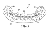
- stop members 39 are formed to facilitate subsequent positioning of the transfer apparatus relative to the patient's teeth during a bonding procedure.
- the stop members 39 may be made by placing curable material on the replica 20 or alternatively within the channel of the tray 30.
- the stop members 39 are located along the curved longitudinal axis of the tray channel and next to the bottom wall portion of the tray 30 that defines the channel.
- three spaced-apart stop members 39 are made by placing curable material across occlusal sections of the replica dental arch 20.
- One stop member 39 is formed near the center of the replica dental arch 20, while the other two stop members 39 are formed near the right end and left end respectively of the replica dental arch 20.
- a single stop member 39 may be provided that extends along a substantial majority of the curved longitudinal axis of the replica dental arch 20.
- two stop members 39 may be provided, each of which extends along a majority of the left quadrant and the right quadrant respectively of the replica dental arch 20 and follows the curved longitudinal axis of the arch.
- one or more stop members 39 may be provided along the lingual surfaces and/or the facial surfaces of the replica dental arch 20. Lingual and facial stop members may be particularly advantageous to ensuring proper fitting and placement of the transfer apparatus in instances when the patient's maloccluded teeth present diverging tooth angulations.
- the stop members 39 may be made from a variety of materials. Suitable materials include, for example, an orthodontic or dental adhesive, a dental restorative material, or a bite registration material. An example of a suitable bite registration material is "Imprint Bite" bite registration material from 3M Espe.
- the stop members 39 are made of a thermosetting material that, after hardening, does not substantially soften upon contact with heat.
- the stop members 39 transmit actinic radiation and retain their shape over extended periods of time.
- the tray 30 is placed over the replica dental arch 20 including the unhardened stop members 39.
- the tray 30 is pressed toward the replica arch 20 with sufficient force to deform the shape of the unhardened stop members 39 and bring the tray 30 to a desired position relative to the replica 20 as the stop members 39 are flattened.
- This desired position is somewhat adjacent the replica 20, but is sufficiently spaced from the replica 20 so that a quantity of matrix material may be received between the tray 30 and the replica 20 as described below.
- the stop members 39 are then allowed to harden. Once hardened, the stop members 39 have a gingival or tooth-facing surface that matches the occlusal surface of the facing occlusal section of the replica tooth or teeth 22.
- a matrix material is then applied, either to the replica 20 or to the channel of the tray 30.
- the matrix material may be applied to the replica 20 as it appears in Fig. 5 , using a syringe, brush or other technique.
- the matrix material may be preferable to invert the tray 30 such that the open side of the channel of the tray 30 is facing upwardly as shown in Fig. 6 . If the tray 30 is inverted, the tray 30 is not initially trimmed along the outermost distal sides (corresponding to the ends of the dental arch) so that the liquid matrix material is contained within the tray channel.
- the replica 20 is positioned in the tray 30 such that the matrix material 40 is received in the channel of the tray 30 and between the tray 30 and the replica 20.
- the matrix material 40 surrounds the appliance 34 and also extends along the labial and lingual surfaces of the replica tooth 22.
- the matrix material 40 extends along the bottom and side wall surfaces of the tray 30.
- the stop members 39 serve to properly position the tray 30 from the external surfaces of the replica teeth 22 as the matrix material 40 is received in the tray channel. The matrix material 40 is then allowed to harden.
- the matrix material 40 surrounds each appliance 34 and the entire replica arch 20 except in areas near the stop members 39, which remain in contact with the occlusal sections of the replica 20.
- the matrix material 40 and the stop members 39 chemically bond to each other as the matrix material 40 has hardened, so that the stop members 39 are not unintentionally detached during the subsequent steps.
- the matrix material 40 has a relatively low viscosity before hardening so that intimate contact between the matrix material 40 and each appliance 34 is assured.
- the matrix material 40 is able to substantially penetrate in various recesses, cavities and other structural features of each appliance 34 so that a secure connection between the appliance 34 and the matrix material 40 can be established.
- An example of a suitable matrix material having a relatively low viscosity is a silicone material such as "RTV615" silicone material from General Electric as mentioned above.
- the relatively low viscosity of this silicone matrix material also assures that the matrix material will assume a configuration that closely matches the shape of the adjacent surfaces of the replica teeth 22.
- the matrix material 40 may comprise a dental impression material or a bite registration material. Suitable materials include polyvinylsiloxane impression material, such as Memosil 2 brand vinyl polysiloxane material from Heraeus Kulzer Inc., or Peppermint Snap brand clear bite registration material from Discus Dental. If a light-curable adhesive is to be used for bonding the appliances 34 to the patient's teeth, the matrix material 40 is preferably optically clear and transmits actinic radiation without substantial absorption.
- the tray 30, together with the matrix material 40 and the appliances 34 are detached from the replica 20.
- the use of the release agent as mentioned above helps facilitate detaching of the appliances 34 from the corresponding replica teeth 22. Excess material of the tray 30 and excess matrix material 40 are then trimmed as desired as discarded.
- the resultant trimmed transfer apparatus 44 (comprising the tray 30, the matrix material 40, the stop members 39 and the appliances 34) is shown in cross-sectional view in Fig. 7 .
- the patient's teeth that are to receive appliances are isolated using cheek retractors, tongue guards, cotton rolls, dry angles and/or other articles as needed.
- the teeth are then thoroughly dried using pressurized air from an air syringe.
- Etching solution (such as 3M Unitek Transbond XT brand etching gel) is then dabbed onto the teeth in the general area that is to be covered by the appliances 34, taking care to prevent the etching solution from flowing into interproximal contacts or engaging the skin or gingiva.
- the solution is rinsed away from the teeth with a stream of water for fifteen seconds.
- the patient's teeth are then dried by the application of pressurized air from an air syringe (for example, for a time period of thirty seconds) and excess water is removed by suction. Care should also be undertaken to ensure that the saliva does not come in contact with the etched enamel surfaces. Cotton rolls and other absorbent devices are replaced as needed, again making sure that saliva does not contact the etched enamel. Air from the air syringe may then be applied to the teeth again to ensure that the teeth are thoroughly dried.
- a bonding adhesive is applied to the hardened adhesive 36 and/or the selected areas of the patient's teeth.
- the adhesive is a two-component adhesive as depicted in Fig. 7 .
- the first component 41 is a Transbond brand XT moisture insensitive primer
- the second component 43 is Transbond brand Plus self-etching primer, both from 3M Unitek.
- the first component 41 is applied to the hardened adhesive 36 and the second component 43 is applied to the area of the patient's tooth that is to receive the appliance 34.
- the patient's tooth is designated by the numeral 42.
- the tray 30 is then positioned over the corresponding teeth and seated, optionally with a swinging, hinge-type motion. Since the shape of the cavity of the matrix material 40 and the stop members 39 together match the shape of the underlying teeth, the appliances 34 are simultaneously seated against the underlying teeth 42 at precisely the same locations corresponding to the previous position of the appliances 34 on the replica 20.
- the tray 30 has a shape that is complemental to the patient's tooth structure, and has sufficient stiffness to press the appliances 34 against the teeth 42 as the adhesive cures without the application of external pressure.
- external pressure may also be applied to the occlusal, labial and buccal surfaces of the tray 30 until such time as the bonding adhesive has sufficiently hardened.
- finger pressure may be used to firmly press the appliances 34 against the enamel surfaces of the patient's teeth 42.
- Suitable two-component chemical curing adhesives include Sondhi brand Rapid-Set indirect bonding adhesive, Unite brand adhesive and Concise brand adhesive, all from 3M Unitek.
- Sondhi brand Rapid-Set indirect bonding adhesive Unite brand adhesive
- Concise brand adhesive all from 3M Unitek.
- a resin-modified glass ionomer cement may be employed.
- the tray 30 is carefully removed from the patient's dental arch.
- the tray 30 is first separated from the matrix material 40, which remains in place over the dental arch along with the appliances 34.
- the matrix material 40 is detached from the appliances 34.
- a hand instrument such as a scaler may be used to help hold each appliance 34 against the surface of the respective tooth 42 of the patient as the matrix material 40 is peeled away from the appliances 34.
- the use of a scaler to help avoid fracturing the fresh adhesive bond is optional.
- the tray 30 may be separated from the matrix material 40 before the bonding adhesive has hardened. This option is particularly useful when the bonding adhesive is a light-curable adhesive.
- an archwire is placed in the slots of the appliances 34 and ligated in place.
- Suitable ligation devices include tiny, elastic O-rings as well as sections of wire that are tied in a loop around the appliances 34.
- the appliances 34 may be self-ligating appliances that include a latch for releasably engaging the archwire such as those described in U.S. Patent no. 6,302,688 and PCT Publication No. WO02/089693 .
- the hardened adhesive 36 provides a contoured bonding surface for the base of the corresponding appliance 34.
- the configuration of this bonding surface closely matches the shape of the patient's tooth surface and consequently facilitates the subsequent bond (using the bonding adhesive components 41, 43) that is established between the appliance 34 and the tooth 42.
- the bonding surface reduces the likelihood that the appliance 34 will become unintentionally detached from the tooth during the course of treatment.
- the use of the spacer material 26 in combination with the stop members 39 in the method described above is a significant advantage in that an appropriate region for receiving matrix material 40 in the tray 30 is provided.
- the spacer material 26 and the stop members 39 can be shaped as needed to provide precisely the volume and configuration of region as may be desired.
- the spacer material 26 and the stop members 39 may help ensure that a uniform thickness of matrix material is subsequently provided around the substantial extent of the tooth 42 with the exception of the areas adjacent the appliance 34 and the occlusal section of the dental arch adjacent the stop members 39.
- the use of the spacer material 26 facilitates the use of a matrix material having a relatively low viscosity, such as a matrix material having a liquid consistency.
- the tray 30 is relatively stiff, and consequently maintains its shape during forming of the matrix material 40.
- the transfer apparatus 44 is constructed such that the tray 30 (other than the stop members 39) does not directly contact the patient's teeth or gingival tissue. Instead, only the matrix material 40 and the stop members 39 come into contact with the patient's teeth.
- the relatively soft matrix material 40 is flexible and can accommodate a limited amount of tooth movement.
- the teeth of the patient may have slightly shifted between the time that the impressions are taken and the time that the transfer apparatus 44 is fitted in the patient's oral cavity for bonding the appliances 34.
- the matrix material 40 has sufficient flexibility to comply with small shifts or adjustments in the patient's tooth positions, so that the appliances 34 are properly bonded to the intended, pre-determined locations on the patient's tooth.
- the matrix material 40 preferably has a viscosity before curing that is less than about 60,000 cp. More preferably, the matrix material 40 has a viscosity before curing that is less than about 25,000 cp. Most preferably, the matrix material 40 has a viscosity before curing that is less than about 8000 cp.
- the matrix material 40 has a Shore A hardness that is in the range of about 10 to about 80, more preferably in the range of about 30 to about 60 and most preferably in the range of about 40 to about 50.
- the stop members 39 are relatively inflexible and have a Shore A hardness that is greater than the Shore A hardness of the matrix material 40.
- the stop members 39 have a Shore A hardness that is greater than about 60 and more preferably is greater than about 90.
- the spacer material 26 enhances control over construction of the transfer apparatus, including the resultant shape of the tray 30 and the contained matrix material 40.
- the spacer material 26 enables the resultant thickness of the matrix material 40 to be relatively uniform and preferably relatively thin. This uniform thickness of relatively small dimension facilitates curing of a photocurable adhesive used to bond the appliances to the patient's teeth.
- the uniform thickness of matrix material 40 helps to ensure that the light-curable adhesive beneath each appliance 34 is sufficiently cured to the same extent from one appliance 34 to the next. In this manner, the user need not compensate for varying thicknesses of matrix material and the curing times associated with each quantity of adhesive need not vary from one appliance 34 to the next.
- FIG. 8 and 9 Another embodiment of the invention is illustrated in Figs. 8 and 9 . Except as described below, this embodiment is identical to the embodiment set out above in connection with Figs. 1-7 .
- a spacer material 26a is similar to the spacer material 26 except that the spacer material has one or more openings 29a that extend along the occlusal sections of the replica teeth 22.
- the spacer material 26a may have three openings 29a that are located (with respect to the replica 20) in approximately the same positions as the stop members 39 shown in Fig. 5 .
- An interconnecting web (not shown) of the spacer material 26a extends between adjacent openings 29a and over remaining regions of the occlusal sections of the replica teeth 22.
- the spacer material 26a also includes cavities (such as cavity 28a) that are similar to the cavities 28 described above.
- a tray 30a is formed over the spacer material 26a (including over the openings 29a) as shown in Fig. 9 .
- This forming process is essentially the same as the forming process described in connection with Fig. 4 , except that in this instance a portion of the tray material is drawn into the openings 29a and contacts the adjacent, occlusal sections of the replica teeth 22.
- Each of these portions that are drawn into the openings 29a provides a stop member 31a that, in use, functions in a manner similar to the stop members 39 set out above.
- the stop members 31a are integrally connected to a bottom wall portion of the tray 30a and together form a single, unitary body, the handling of separate components during assembly of the transfer apparatus is eliminated.
- a bonding composition may be applied to the base of each appliance 34 by the manufacturer and then packaged in a container for shipment to the practitioner, as described in published U.S. patent application no. 2005-0074716, April 7, 2005 , entitled "Apparatus for Indirect Bonding of Orthodontic Appliances and Method of Making the Same".
- the practitioner can simply remove the transfer apparatus from the container and immediately place the appliances on the patient's teeth.
- the bonding composition of at least one appliance 34 may differ from the bonding composition of at least one other appliance 34 in the transfer apparatus in terms of composition, properties or characteristics, as described in published U.S. patent application no. 2005-0133384, June 23, 2005 entitled “Packaged Orthodontic Assembly with Adhesive Precoated Appliances", such that the bonding composition can be tailored to enhance the bond between the particular selected appliance 34 and its intended tooth.
- the transfer apparatus may be used for bonding only a single appliance to a patient's tooth.
- a portion of the transfer apparatus described above may be used to bond a single appliance to a single tooth subsequent to the time that other appliances are bonded, such as in instances where access to the tooth is initially hindered by other teeth.
- a portion of the transfer apparatus described above may be used to re-bond an appliance that has unintentionally debonded from the tooth, or to bond a new appliance to a tooth to replace the original appliance.
Abstract
Description
- This invention relates to method and apparatus for bonding orthodontic appliances such as brackets to a patient's teeth. The present invention also relates to methods for indirect bonding of orthodontic appliances.
- Orthodontic treatment involves movement of malpositioned teeth to desired locations in the oral cavity. Orthodontic treatment can improve the patient's facial appearance, especially in instances where the teeth are noticeably crooked or where the jaws are out of alignment with each other. Orthodontic treatment can also enhance the function of the teeth by providing better occlusion during mastication.
- One common type of orthodontic treatment involves the use of tiny, slotted appliances known as brackets. The brackets are fixed to the patient's teeth and an archwire is placed in the slot of each bracket. The archwire forms a track to guide movement of teeth to desired locations.
- The ends of orthodontic archwires are often connected to small appliances known as buccal tubes that are, in turn, secured to the patient's molar teeth. In many instances, a set of brackets, buccal tubes and an archwire is provided for each of the patient's upper and lower dental arches. The brackets, buccal tubes and archwires are commonly referred to collectively as "braces".
- In many types of orthodontic techniques, the precise position of the appliances on the teeth is an important factor for helping to ensure that the teeth move to their intended final positions. For example, one common type of orthodontic treatment technique is known as the "straight-wire" technique, where the archwire lies in a horizontal plane at the conclusion of treatment. Consequently, if a bracket is attached to the tooth at a location that is too close to the occlusal or outer tip of the tooth, the orthodontist using a straight-wire technique will likely find that the tooth in its final position is unduly intruded. On the other hand, if the bracket is attached to the tooth at a location closer to the gingiva than is appropriate, it is likely that the final position of the tooth will be more extruded than desired.
- In general, orthodontic appliances that are adapted to be adhesively bonded to the patient's teeth are placed and connected to the teeth by either one of two techniques: a direct bonding technique, or an indirect bonding technique. In the direct bonding technique, the appliance and adhesive are grasped with a pair of tweezers or other hand instrument and placed by the practitioner on the surface of the tooth in an approximate desired location. Next, the appliance is shifted along the surface of the tooth as needed until the practitioner is satisfied with its position. Once the appliance is in its precise, intended location, the appliance is pressed firmly onto the tooth to seat the appliance in the adhesive. Excess adhesive in areas adjacent the base of the appliance is removed, and the adhesive is then allowed to cure and fix the appliance firmly in place.
- While the direct bonding technique described above is in widespread use and is considered satisfactory by many, there are shortcomings that are inherent with this technique. For example, access to surfaces of malposed teeth may be difficult. In some instances, and particularly in connection with posterior teeth, the practitioner may have difficulty seeing the precise position of the bracket relative to the tooth surface. Additionally, the appliance may be unintentionally dislodged from its intended location during the time that the excess adhesive is being removed adjacent the base of the appliance.
- Another problem associated with the direct bonding technique described above concerns the significant length of time needed to carry out the procedure of bonding each appliance to each individual tooth. Typically, the practitioner will attempt to ensure that each appliance is positioned in its precise, intended location before the adhesive is cured, and some amount of time may be necessary before the practitioner is satisfied with the location of each appliance. At the same time, however, the patient may experience discomfort during the procedure and have difficulty in remaining relatively motionless, especially if the patient is an adolescent. As can be appreciated, there are aspects of the direct bonding technique that can be considered a nuisance for both the practitioner and for the patient.
- Indirect bonding techniques avoid many of the problems noted above. In general, indirect bonding techniques known in the past have involved the use of a placement device or transfer apparatus having a shape that matches the configuration of at least part of the patient's dental arch. One type of placement device or transfer apparatus is often called a "transfer tray" and typically has a cavity for receiving a number of teeth simultaneously. A set of appliances such as brackets are releasably connected to the tray at certain, predetermined locations.
- Other types of transfer apparatus used in indirect bonding are often referred to as "jigs" and resemble a framework that contacts one or more teeth at certain locations. For example, a jig constructed for use in bonding a single appliance to a single tooth may have an arm that extends over and contacts an incisal section of the tooth. An appliance such as a bracket is releasably connected to the jig at a certain, predetermined location relative to the tooth.
- During the use of orthodontic transfer apparatus for indirect bonding, an adhesive is typically applied to the base of each appliance by the orthodontist or a staff member. The device is then placed over the patient's teeth and remains in place until such time as the adhesive hardens. Next, the apparatus is detached from the teeth as well as from the appliances, with the result that all of the appliances previously connected to the apparatus are now bonded to respective teeth at their intended, predetermined locations.
- In more detail, one method of indirect bonding of orthodontic appliances using the transfer tray described above includes the steps of taking an impression of each of the patient's dental arches and then making a replica plaster or "stone" model from each impression. Next, the appliances are bonded to the stone models at desired locations. Optionally, the bonding adhesive can be a chemical curing adhesive (such as Concise brand adhesive from 3M) or a light-curable adhesive (such as Transbond XT brand adhesive or Transbond LR brand adhesive from 3M). Optionally, the brackets may be adhesive precoated brackets such as those described in
U.S. Patent Nos. 5,015,180 ,5,172,809 ,5,354,199 and5,429,229 . - The transfer tray is then made by placing a matrix material over the model as well as over the appliances placed in the model. For example, a plastic sheet matrix material may be held by a frame and exposed to radiant heat. Once the plastic sheet material has softened, it is placed over the model and the appliances. Air in the space between the sheet material and the model is then evacuated, and the plastic sheet material assumes a configuration that precisely matches the shape of the replica teeth of the stone model and attached appliances.
- The plastic sheet matrix material is then allowed to cool and harden to form a tray. The tray and the appliances (which are embedded in an interior wall of the tray) are then detached from the stone model. If the cured adhesive that was used to bond the appliances to the stone model remains on the base of the appliances after detachment from the stone model, the adhesive serves as a "custom" base having a concave contour that precisely replicates the convex contour of the previous attachment location of the stone model, as well as the convex configuration of the intended mounting location of the appliances on the patient's teeth.
- Once the patient has returned to the practitioner's office, a quantity of adhesive is placed on the base of each appliance, and the tray with the embedded appliances is then placed over the matching portions of the patient's dental arch. Since the configuration of the interior of the tray closely matches the respective portions of the patient's dental arch, each appliance is ultimately positioned on the patient's teeth at precisely the same location that corresponds to the previous location of the same appliance on the stone model.
- Indirect bonding techniques offer a number of advantages over direct bonding techniques. For one thing, and as indicated above, it is possible to bond a plurality of appliances to a patient's dental arch simultaneously, thereby avoiding the need to bond each appliance in individual fashion. In addition, the transfer apparatus helps to locate the appliances in their proper, intended positions such that adjustment of each appliance on the surface of the tooth before bonding is avoided. The increased placement accuracy of the appliances that is often afforded by indirect bonding techniques helps ensure that the patient's teeth are moved to their proper, intended positions at the conclusion of treatment.
- In recent years, many improvements have been made in the field of indirect bonding. For example,
U.S. Patent No. 5,971,754 describes a two-component indirect bonding adhesive with a relatively fast curing time that reduces the length of time that the tray must be firmly held against the patient's teeth.U.S. Patent No. 6,123,544 describes a transfer tray that receives movable arms for placing appliances on the patient's teeth once the tray is positioned in the oral cavity. Published U.S. Patent Application entitled "METHOD AND APPARATUS FOR INDIRECT BONDING OF ORTHODONTIC APPLIANCES" (U.S. Publication No. 2004-0219471, published on November 4, 2004 ), describes among other things a transfer apparatus with an improved matrix material for releasably holding appliances in place. Published U.S. Patent Application entitled "APPARATUS FOR INDIRECT BONDING OF ORTHODONTIC APPLIANCES AND METHOD OF MAKING THE SAME" (U.S. 2005-0074716, April 7, 2005 ) describes among other things a transfer apparatus that includes at least one appliance having a base with a contour that is a replica of a contour of a portions of the patient's tooth structure, and a bonding composition on the base for bonding to the patient's tooth structure. - There is a continuing need in the art to improve the methods of making transfer apparatus. For example, it would be desirable to reduce the amount of time needed to make transfer apparatus. However, it is also important to ensure that any new methods of construction do not adversely affect the ultimate placement accuracy of the appliances on the patient's teeth during a bonding procedure, so that the teeth are moved to their proper, intended positions at the conclusion of the treatment program.
- The present invention is directed toward a method of constructing transfer apparatus for orthodontic indirect bonding, wherein a spacer material is applied to a replica of the patient's dentition. The spacer material has at least one cavity for receiving an orthodontic appliance, and remains on the replica while a tray is formed over the spacer material. The cavity is located in the spacer material at a certain, pre-selected position, with the result that the appliance is ultimately positioned in its proper, intended location with respect to the replica.
- In more detail, the present invention in one aspect concerns a method of making transfer apparatus for orthodontic indirect bonding comprising:
- providing a replica of a patient's dentition;
- applying a spacer material over the replica of the patient's dentition, wherein the spacer material has at least one cavity;
- placing an orthodontic appliance in a cavity of the spacer material in an orientation such that a base of the appliance is in contact with a replica tooth of the replica dentition; and
- forming a tray over the spacer material.
- In another aspect, the present invention concerns an assembly for making transfer apparatus for use in indirect bonding of orthodontic appliances. The assembly comprises:
- a dentition replica including a number of replica teeth;
- a spacer material extending over at least part of the replica including at least part of the replica teeth, the spacer material having a number of cavities each located next to one of the replica teeth;
- a set of orthodontic appliances each located in a respective one of the cavities; and
- a tray extending over the cavities and releasably connected to the spacer material.
- In yet another aspect, the present invention concerns a method of making transfer apparatus for orthodontic indirect bonding that comprises:
- providing a replica of a patient's dentition;
- obtaining a set of digital data representing the shape of the patient's dentition;
- making a spacer material using the digital data in a rapid prototyping process;
- applying the spacer material to the replica of the patient's dentition; and forming a tray over the spacer material.
- Further details of the invention are defined in the features of the claims.
- The following aspects are preferred embodiments of the invention:
- 1. A method of making transfer apparatus for orthodontic indirect bonding comprising:
- providing a replica of a patient's dentition;
applying a spacer material over the replica of the patient's dentition, wherein the spacer material has at least one cavity;
placing an orthodontic appliance in a cavity of the spacer material in an orientation such that a base of the appliance is in contact with a replica tooth of the replica dentition; and - forming a tray over the spacer material.
- providing a replica of a patient's dentition;
- 2.A method of making transfer apparatus for orthodontic indirect bonding according to aspect 1 and including the act of temporarily fixing the base of the appliance to the replica tooth of the replica.
- 3.A method of making transfer apparatus for orthodontic indirect bonding according to aspect 2 wherein the act of forming a tray over the spacer material includes the act of forming the tray over the spacer material after the base of the appliance is temporarily fixed to the replica tooth of the replica.
- 4.A method of making transfer apparatus for orthodontic indirect bonding according to aspect 1 and including the acts of:
- removing the tray from the spacer material;
detaching the spacer material from the replica; - directing a quantity of matrix material onto at least one of the tray and the replica; and
- placing the tray over the replica such that the matrix material is between the tray and the replica.
- removing the tray from the spacer material;
- 5.A method of making transfer apparatus for orthodontic indirect bonding according to aspect 4 wherein the act of directing a quantity of matrix material onto at least one of the tray and the replica includes the act of at least partially surrounding the orthodontic appliance with the matrix material.
- 6.A method of making transfer apparatus for orthodontic indirect bonding according to aspect 4 wherein the Shore A hardness of the matrix material is in the range of about 10 to about 80.
- 7.A method of making transfer apparatus for orthodontic indirect bonding according to aspect 4 wherein the Shore A hardness of the matrix material is in the range of about 30 to about 60.
- 8.A method of making transfer apparatus for orthodontic indirect bonding according to aspect 4 wherein the matrix material is a curable material and has a viscosity before curing of less than about 60,000 cp.
- 9.A method of making transfer apparatus for orthodontic indirect bonding according to aspect 4 wherein the matrix material is a curable material and has a viscosity before curing of less than about 25,000 cp.
- 10. A method of making transfer apparatus for orthodontic indirect bonding according to aspect 1 and including the act of moving the transfer apparatus into a patient's oral cavity in order to locate the orthodontic appliance adjacent one of the patient's teeth.
- 11. A method of making transfer apparatus for orthodontic indirect bonding according to aspect 1 wherein the spacer material includes a number of cavities, each adopted to receive a respective orthodontic appliance.
- 12. A method of making transfer apparatus for orthodontic indirect bonding according to aspect 1 and including the acts of obtaining digital data representing at least part of the configuration of the patient's dentition, and making the spacer material using the digital data.
- 13. A method of making transfer apparatus for orthodontic indirect bonding according to aspect 12 wherein the act of making the spacer material includes the act of using a rapid prototyping process.
- 14. A method of making transfer apparatus for orthodontic indirect bonding according to aspect 12 wherein the act of making the spacer material includes the act of using a stereolithography process.
- 15. A method of making transfer apparatus for orthodontic indirect bonding according to aspect 12 and including the act of using computer software to determine the location of the cavity in the spacer material.
- 16. A method of making transfer apparatus for orthodontic indirect bonding according to aspect 15 wherein the act of using computer software to determine the location of the cavity in the spacer material includes the act of relating the location of the cavity in the spacer material to the patient's dentition.
- 17. A method of making transfer apparatus for orthodontic indirect bonding according to aspect 1 wherein the cavity has a facial side that is closed.
- 18. A method of making transfer apparatus for orthodontic indirect bonding according to aspect 1 wherein the cavity has a facial side that is initially open.
- 19. A method of making transfer apparatus for orthodontic indirect bonding according to aspect 18 and including the act of closing the facial side of the cavity after the appliance has been placed in the cavity.
- 20. A method of making transfer apparatus for orthodontic indirect bonding according to aspect 1 wherein the spacer material has a cavity corresponding to each orthodontic appliance on the patient's dentition.
- 21. A method of making transfer apparatus for orthodontic indirect bonding according to aspect 1 wherein the act of forming the tray over the spacer material includes the act of softening tray material.
- 22. A method of making transfer apparatus for orthodontic indirect bonding according to aspect 1 wherein the act of forming the tray over the spacer material includes the act of using negative pressure to draw tray material into intimate contact with the spacer material.
- 23. A method of making transfer apparatus for orthodontic indirect bonding according to aspect 1 wherein the act of forming the tray over the spacer material includes the act of forming the tray while the appliance is in contact with the replica tooth.
- 24. An assembly for making transfer apparatus for use in indirect bonding of orthodontic appliances comprising:
- a dentition replica including a number of replica teeth;
a spacer material extending over at least part of the replica including at least part of the replica teeth, the spacer material having a number of cavities each located next to one of the replica teeth; - a set of orthodontic appliances each located in a respective one of the cavities; and
- a tray extending over the cavities and releasably connected to the spacer material.
- a dentition replica including a number of replica teeth;
- 25. An assembly for making transfer apparatus for use in indirect bonding of orthodontic appliances according to
aspect 24 wherein the orthodontic appliances are releasably affixed to the replica teeth. - 26. An assembly for making transfer apparatus for use in indirect bonding of orthodontic appliances according to
aspect 24 wherein the spacer material is deformable to release the appliances from the cavities. - 27. An assembly for making transfer apparatus for use in indirect bonding of orthodontic appliances according to
aspect 24 wherein the replica teeth each include a facial section, an occlusal section and a lingual section, and wherein the spacer material extends over the facial section of at least a majority of the replica teeth. - 28. An assembly for making transfer apparatus for use in indirect bonding of orthodontic appliances according to aspect 27 wherein the spacer material extends over the occlusal section of at least a majority of the replica teeth.
- 29. An assembly for making transfer apparatus for use in indirect bonding of orthodontic appliances according to
aspect 28 wherein the spacer material extends over at least part of the lingual section of at least a majority of the replica teeth. - 30. An assembly for making transfer apparatus for use in indirect bonding of orthodontic appliances according to
aspect 24 wherein the spacer material is selected from the group of thermoset materials, thermoset elastomer materials and composite materials. - 31. An assembly for making transfer apparatus for use in indirect bonding of orthodontic appliances according to
aspect 24 and including an adhesive for releasably fixing the spacer material to the dentition replica. - 32. An assembly for making transfer apparatus for use in indirect bonding of orthodontic appliances according to
aspect 24 wherein the dentition replica comprises a dentition replica of a patient undergoing orthodontic treatment. - 33. A method of making transfer apparatus for orthodontic indirect bonding comprising:
- providing a replica of a patient's dentition;
obtaining a set of digital data representing the shape of the patient's dentition; making a spacer material using the digital data in a rapid prototyping process; applying the spacer material to the replica of the patient's dentition; and - forming a tray over the spacer material.
- providing a replica of a patient's dentition;
- 34. A method of making transfer apparatus for orthodontic indirect bonding according to aspect 33 and including the act of providing at least one cavity in the spacer material to receive an orthodontic appliance.
- 35. A method of making transfer apparatus for orthodontic indirect bonding according to
aspect 34 and including the act of placing an orthodontic appliance in at least one cavity of the spacer material such that the appliance is in contact with the replica. - 36. A method of making transfer apparatus for orthodontic indirect bonding according to aspect 33 and including the acts of:
- removing the tray from the spacer material;
detaching the spacer material from the replica; - directing a quantity of matrix material onto at least one of the tray and the replica; and
- placing the tray over the replica such that the matrix material is between the tray and the replica.
- removing the tray from the spacer material;
- 37. A method of making transfer apparatus for orthodontic indirect bonding according to
aspect 36 and including the act of placing an orthodontic appliance next to the replica, and wherein the act of directing a quantity of matrix material onto at least one of the tray and the replica includes the act of at least partially surrounding the orthodontic appliance with the matrix material. - 38. A method of making transfer apparatus for orthodontic indirect bonding according to aspect 33 wherein the act of making a spacer material using the digital data in a rapid prototyping process includes the act of using at least one of a stereolithography process and a thermojet printing process.
-
-
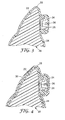
Fig. 1 is a top and front view showing a physical replica of one dental arch of an orthodontic patient, illustrating an example of a replica of a patient's tooth structure and adjacent gingival tissue as they might appear before the commencement of treatment; -
Fig. 2 is a view of the dental arch replica shown inFig. 1 , along with a set of orthodontic appliances and spacer material that have been applied to the replica; -
Fig. 3 is an enlarged side cross-sectional view of one of the replica teeth illustrated inFig. 2 along with the appliance and spacer material; -
Fig. 4 is a view somewhat similar toFig. 3 , additionally showing a tray that has been formed over the spacer material; -
Fig. 5 is a view of the tooth structure replica illustrated inFig. 1 after the spacer material and the tray have been detached from the replica, and additionally showing three stop members that have been placed along occlusal sections of the replica teeth; -
Fig. 6 is an enlarged side cross-sectional view of one of the replica teeth, one of the appliances, and one of the stop members depicted inFig. 5 , and additionally showing a quantity of matrix material that has been placed between the replica and the tray shown inFig. 4 after the replica and the tray have been inverted to make a transfer apparatus; -
Fig. 7 is an enlarged side cross-sectional view illustrating the act of applying the transfer apparatus to one of the patient's teeth; -
Fig. 8 is a view somewhat similar toFig. 3 but in accordance with another embodiment of the present invention; and -
Fig. 9 is a view somewhat similar toFig. 4 but in accordance with the embodiment illustrated inFig. 8 . - A method for indirect bonding of one or more orthodontic appliances in accordance with one aspect of the present invention is depicted in
Figs. 1-7 .Fig. 1 illustrates areplica 20 of a portion of a dental arch of an orthodontic patient. For exemplary purposes, thereplica 20 represents the patient's lower dental arch. However, a replica of a patient's upper dental arch may be provided as an addition to or as an alternative to the lower dental arch replica as shown. As a further option, thereplica 20 may represent only a portion of a dental arch, such as a quadrant of an arch or only one or two teeth of a dental arch. In the example illustrated, thereplica 20 includes a number ofreplica teeth 22, corresponding to each tooth of the patient's lower dental arch. - As one option, the
replica 20 is made by first taking an impression of the patient's lower dental arch, using care to avoid undue distortion. An alginate impression material may be used, such as "Palgat" Plus brand alginate impression material from 3M Espe. Alternatively, a hydrocolloid or vinyl polysiloxane impression material may be used, such as "Position Penta" brand vinyl polysiloxane impression material from 3M ESPE. - The model or
replica 20 is then made from the impression. Optionally, thereplica 20 is a "stone" model made from plaster of Paris, using care to avoid bubbles in the model. If small voids are present, the voids can be filled with a small, additional quantity of plaster of Paris. As an option, thereplica 20 includes only thereplica teeth 22 and sufficient replicagingival tissue 24 to hold thereplica teeth 22 together. - As an alternative, the
replica 20 may be made using digital data that is representative of the patient's teeth and adjacent gingival tissue. The digital data may be obtained by use of a hand-held intra-oral scanner or other device known in the art. As another option, the digital data may be obtained by scanning an impression or a stone model. Thereplica 20 may then be made from the digital data using, for example, a stereo lithographic printer. - The
replica 20 may also be made using digital data in conjunction with a milling process. For example, a CNC milling machine, similar to the CAD/CIM milling machines sold by Cerec Network of Buelach, Switzerland, may be used to mill replicas made of ceramic, composite or other materials. An intra-oral camera, similar to the cameras associated with the Cerec machines, may be used to obtain digital data representing the shape of the dental arches. Alternatively, a scanner may be used to scan an impression or a model of an impression to obtain the digital data. - Preferably, the
replica 20 is an accurate representation of the patient's oral structure. In particular, thereplica teeth 22 will have a configuration and orientation that are identical to the configuration and orientation of the corresponding teeth of the orthodontic patient. In addition, the replicagingival tissue 24 will have a shape that matches the shape of the corresponding portions of the gingival tissue of the patient. - A thin layer of a release agent is then applied to the
replica 20 and allowed to dry. An example of a suitable release agent is a water soluble polyvinyl alcohol, such as "PA0810" from PTM & W Company of Santa Fe Springs, California. - Next, and as shown in
Figs. 2 and3 , aspacer material 26 is applied to thereplica 20. Thespacer material 26 preferably comprises a custom-made material that is optionally formed using a rapid prototyping method. Examples of suitable rapid prototyping methods include stereolithography, thermojet printing and the like. Preferably, digital data representing the shape of a portion of the patient's dental arch is used in the rapid prototyping method to make thespacer material 26. - The
spacer material 26 includes a number of pockets orcavities 28, each of which has a shape adapted to complementally receive a correspondingorthodontic appliance 34. For example, if an orthodontic bracket is intended to be received in one of thecavities 28,such cavity 28 optionally has an occlusal wall portion, a mesial wall portion, a gingival wall portion, a distal wall portion and a facial wall portion that match the configuration of the occlusal side, the mesial side, the gingival side, the occlusal side and the facial side respectively of the bracket. As another option, the gingival wall portion may be omitted to facilitate subsequent removal of the transfer apparatus from the patient's dental arch. Preferably, thecavities 28 include small protrusions that extend into and are complementally received in an archwire slot, a vertical slot between tiewings, and/or other features of the appliance. Thecavities 28 are constructed slightly smaller than the correspondingappliance 34 in order to each firmly hold theorthodontic appliance 34 in place. However, thespacer material 26 is sufficiently flexible to enable theappliance 34 to be released from thecavity 28 when desired. - Each of the
cavities 28 is positioned in a location that corresponds to the subsequent desired location of anorthodontic appliance 34 on the dental arch. For instance, each of thecavities 28 may be positioned to place the center of theappliance 34 in a location corresponding to the facial axis point (or "FA" point) of thecorresponding replica tooth 22, although other locations are also possible. As will be described below, thespacer material 26 functions to subsequently provide clearance in the transfer apparatus for receiving theorthodontic appliances 34. - Preferably, the locations of the
cavities 28 and consequently the ultimate position of the placedappliance 34 are determined by computer software that has access to digital data representing a virtual model of thereplica 20. The software preferably includes subprograms suitable to analyze the existing malocclusion of the patient and selectproper appliances 34 for treatment of the particular malocclusion at hand. Once theappliances 34 are selected and the locations of thecavities 28 for receiving the appliances are determined, the software instructs automated apparatus (such as apparatus using the rapid prototyping method mentioned earlier) to make thespacer 26 in custom fashion. Optionally, the software enables the practitioner, patient or other observer to see on a monitor or other video output a virtual representation of the patient's teeth as they should appear at the conclusion of treatment using the selectedappliances 34 placed on certain locations of the teeth. - Preferably, the software includes subprograms for selecting
appliances 34, analyzing malocclusions and/or predicting tooth movement and final positions of the teeth. An example of software for choosingappliances 34 is described in publishedU.S. patent application 2003-0163291, August 28, 2003 , entitled "Selection of Orthodontic Brackets". Optionally, the software includes subprograms for making customorthodontic appliances 34 using, for example, a computer numerical control milling machine, instead of selectingappliances 34 from an existing set of appliances as mentioned above. As an additional option, an orthodontic archwire may be placed in the slots of theappliances 34 and ligated in place. This step serves to further reduce the patient's time that is subsequently spent in the chair. - Preferably, the
spacer material 26 extends over at least a majority of the facial surface area, the occlusal surface area and the lingual surface area of thereplica teeth 22. However, thespacer material 26 may be omitted from contacting certain surfaces of thereplica teeth 22 if desired, such as the lingual surface area of thereplica teeth 22. In the illustrated embodiment, thespacer material 26 extends over the replicagingival tissue 24 as well as the lingual tooth areas. - Preferably, the
spacer material 26 is provided as an integral unitary section of material, such that separate handling of the two or more sections of material is avoided. However, other constructions are also possible. For example, thespacer material 26 could comprise a number of discrete, ring-shaped sections of material that each receive a corresponding appliance, along with an initially separate preformed sheet of overlay material that is placed over each ring-shaped section of material once the ring-shaped sections are placed on thereplica teeth 22. - The
spacer material 26 can be any one of a number of materials such as a thermoset material. A suitable material is a silicone material, such as "RTV 615" from General Electric. Other suitable materials include, for example, materials used in rapid prototyping processes, such as thermoplastics (including nylons), thermoplastic elastomers and composites (e.g., glass-filled nylons). Examples of such materials include "Sinterstation HiQ Series SLS System" brand materials (including DuraForm brand PA polyamide nylon, DuraForm Brand GF glass-filled nylon, and Somos brand 201 materials), "Viper SLA" brand materials from 3D Systems (including Dreve Otoplatik Fototec brand SL materials and Accura brand SL materials), and "Thermojet" brand materials (including Thermojet brand 88 and Thermojet brand 2000 materials). Optionally, thespacer material 26 may be temporarily held in place on thereplica 20 by use of an adhesive, such as a pressure sensitive adhesive. Preferably, thespacer material 26 is preformed and has the shape of the underlying replica dental arch when thespacer material 26 is relaxed. Alternatively, thespacer material 26 is formed to match the shape of the replica dental arch when it is applied to the latter. Optionally, thespacer material 26 is coated with a layer of pressure sensitive adhesive on one side and initially connected to a sheet of release material until such time as it is needed for use. - An
orthodontic appliance 34 is received in eachcavity 28 of thespacer material 26. In the embodiment illustrated inFigs. 1-7 , theorthodontic appliance 34 is a bracket, although other appliances such as buccal tubes, lingual sheaths, buttons and bondable bite openers are also possible. Theappliances 34 may be placed in thecavities 28 either before or after thespacer material 26 is placed in contact with the replica dental arch. However, if theappliances 34 are placed in thecavities 28 after thespacer material 26 is applied to the replica dental arch, the facial sides of thecavities 28 are initially open and thespacer material 26 preferably includes an initially separate preformed sheet of overlay material that covers the facial sides of thecavities 28 and theappliances 34. - Before the
appliances 34 are placed over the replica dental arch, a quantity of acomposition 36 is placed between each appliance and thecorresponding replica tooth 22. Preferably, thecomposition 36 is a light-curable composition such as a light-curable adhesive, and the adhesive is coated across the base of eachappliance 34. Preferably, theappliances 34 are adhesive precoated appliances that have a layer of light-curable adhesive applied by the manufacturer to the base of eachappliance 34. Such adhesive coated appliances are described inU.S. Patent Nos. 5,015,180 ,5,172,809 ,5,354,199 and5,429,229 , all of which are assigned to the assignee of the present invention. Theappliances 34 may be made of any suitable material such as metal (e.g., stainless steel), ceramic (e.g., translucent polycrystalline alumina) or plastic (e.g., translucent polycarbonate). - If the
appliances 34 are not precoated with adhesive by the manufacturer, a coating ofcomposition 36 such as an orthodontic adhesive may be applied by the practitioner to the base of eachappliance 34. Suitable orthodontic adhesives include composites, compomers, glass ionomers and resin-modified glass ionomers. Examples of light-curable adhesives include Transbond XT brand or Transbond LR brand adhesives from 3M Unitek. Examples of chemical curing adhesives include Concise brand adhesive and Multi-Cure brand glass ionomer cement from 3M Unitek. - Next, the practitioner applies firm pressure to each
appliance 34 in order to ensure that eachappliance 34 is firmly seated on thecorresponding replica tooth 22. The practitioner may apply finger pressure directly to the facial side of theappliances 34. Alternatively, if the facial side of theappliances 34 is not covered by the spacer material, the practitioner may use a scaler or other hand instrument to apply force to the archwire slot of eachappliance 34. - Alternatively, the
appliances 34 may be placed on thereplica teeth 22 by means of robotic equipment. For example, the robotic equipment may include a gripping arm that is programmed to pick anappropriate appliance 34 from a set of appliances and place the selectedappliance 34 on theappropriate replica tooth 22. The robotic arm then proceeds to grasp anotherappliance 34 for placement on anotherreplica tooth 22. Finally, thespacer material 26 is placed over theappliances 34 and thereplica arch 20. - The adhesive is shown in
Figs. 3-4 and6-7 and is not necessarily drawn to scale. Initially, the adhesive 36 is only slightly hardened such that a tack cure is provided. In this manner, theappliances 34 will remain bonded to thereplica teeth 22 when thespacer material 26 is subsequently removed, and yet the adhesive flash that extrudes from the sides of the appliance base remains relatively soft and can be removed without undue effort. - Subsequently, a
tray 30 is formed over thespacer material 26 as illustrated inFig. 4 . Preferably, thetray 30 is shaped by vacuum forming a sheet of material over the sheet ofspacer material 26. A suitable material for thetray 30 is a sheet of polycarbonate such as Makrolon brand material from Bayer or Lexan brand polycarbonate from GE having a thickness of 0.06 inch. Other materials, such as polyethyleneterephthalate glycol ("PETG") may also be used. Heat is applied during the vacuum forming process in order to facilitate conformance of the sheet to the external configuration of thespacer material 26. - Once the
tray 30 has hardened, thetray 30 is detached from thespacer material 26. Thespacer material 26 is then detached from thereplica 20 and theappliances 34 and set aside or discarded. During detachment of thespacer material 26 from thereplica 20, theappliances 34 remain bonded to the replica teeth. - After the flash from excess adhesive 34 is removed from areas adjacent the base of the
appliances 34, the remaining adhesive is more fully cured. As one example, if theappliances 34 are made of metal or other opaque material and if a light-curable adhesive 36 is used, it is preferable to expose thereplica 20 to the curing light for a relatively long amount of time such as 3 to 5 minutes to ensure that the adhesive 36 has sufficiently hardened. As an alternative to light curing chambers , a hand-held curing unit may be used, such as Ortholux XT brand curing unit from 3M Unitek. - As an additional option, the
replica 20 including thereplica teeth 22 may be made from a material that transmits actinic radiation. Suitable materials include epoxy resins that are transparent or translucent when hardened. Preferably, the material is optically clear. An example of a suitable epoxy is E-CAST F-82 clear epoxy resin and No. 302 (or UCE-302) hardener, from United Resin Corporation. Other suitable materials include polyesters and urethanes. The use of transparent or translucent materials is advantageous in instances where theappliances 34 are made of opaque materials, since the actinic radiation can be transmitted through thereplica 20 for curing portions of the adhesive 36 that are located adjacent the middle of the appliance base. Actinic radiation can include wavelengths in the visible range, ultraviolet range, infrared range or any combination thereof, in accordance with the type of photoinitiator contained in the adhesive 36. - Excess portions of the
tray 30 are then trimmed as desired. Next, stopmembers 39 are formed to facilitate subsequent positioning of the transfer apparatus relative to the patient's teeth during a bonding procedure. Thestop members 39 may be made by placing curable material on thereplica 20 or alternatively within the channel of thetray 30. Preferably, once construction of thetransfer apparatus 20 has been completed, thestop members 39 are located along the curved longitudinal axis of the tray channel and next to the bottom wall portion of thetray 30 that defines the channel. - In the illustrated embodiment, three spaced-apart stop
members 39 are made by placing curable material across occlusal sections of the replicadental arch 20. Onestop member 39 is formed near the center of the replicadental arch 20, while the other twostop members 39 are formed near the right end and left end respectively of the replicadental arch 20. However, other constructions are possible. For example, asingle stop member 39 may be provided that extends along a substantial majority of the curved longitudinal axis of the replicadental arch 20. Alternatively, twostop members 39 may be provided, each of which extends along a majority of the left quadrant and the right quadrant respectively of the replicadental arch 20 and follows the curved longitudinal axis of the arch. Additionally, or as an alternative to occlusal stop members, one ormore stop members 39 may be provided along the lingual surfaces and/or the facial surfaces of the replicadental arch 20. Lingual and facial stop members may be particularly advantageous to ensuring proper fitting and placement of the transfer apparatus in instances when the patient's maloccluded teeth present diverging tooth angulations. - The
stop members 39 may be made from a variety of materials. Suitable materials include, for example, an orthodontic or dental adhesive, a dental restorative material, or a bite registration material. An example of a suitable bite registration material is "Imprint Bite" bite registration material from 3M Espe. Preferably, thestop members 39 are made of a thermosetting material that, after hardening, does not substantially soften upon contact with heat. Preferably, thestop members 39 transmit actinic radiation and retain their shape over extended periods of time. - Next, the
tray 30 is placed over the replicadental arch 20 including theunhardened stop members 39. Thetray 30 is pressed toward thereplica arch 20 with sufficient force to deform the shape of theunhardened stop members 39 and bring thetray 30 to a desired position relative to thereplica 20 as thestop members 39 are flattened. This desired position is somewhat adjacent thereplica 20, but is sufficiently spaced from thereplica 20 so that a quantity of matrix material may be received between thetray 30 and thereplica 20 as described below. Thestop members 39 are then allowed to harden. Once hardened, thestop members 39 have a gingival or tooth-facing surface that matches the occlusal surface of the facing occlusal section of the replica tooth orteeth 22. - A matrix material is then applied, either to the
replica 20 or to the channel of thetray 30. For example, if the matrix material is relatively viscous and resembles a semiliquid or gel, the matrix material may be applied to thereplica 20 as it appears inFig. 5 , using a syringe, brush or other technique. Alternatively, if the matrix material has a relatively low viscosity and resembles a liquid, it may be preferable to invert thetray 30 such that the open side of the channel of thetray 30 is facing upwardly as shown inFig. 6 . If thetray 30 is inverted, thetray 30 is not initially trimmed along the outermost distal sides (corresponding to the ends of the dental arch) so that the liquid matrix material is contained within the tray channel. - Subsequently, the
replica 20 is positioned in thetray 30 such that thematrix material 40 is received in the channel of thetray 30 and between thetray 30 and thereplica 20. As shown inFig. 6 , thematrix material 40 surrounds theappliance 34 and also extends along the labial and lingual surfaces of thereplica tooth 22. Moreover, thematrix material 40 extends along the bottom and side wall surfaces of thetray 30. Thestop members 39 serve to properly position thetray 30 from the external surfaces of thereplica teeth 22 as thematrix material 40 is received in the tray channel. Thematrix material 40 is then allowed to harden. - Preferably, the
matrix material 40 surrounds eachappliance 34 and theentire replica arch 20 except in areas near thestop members 39, which remain in contact with the occlusal sections of thereplica 20. Preferably, thematrix material 40 and thestop members 39 chemically bond to each other as thematrix material 40 has hardened, so that thestop members 39 are not unintentionally detached during the subsequent steps. - Preferably, the
matrix material 40 has a relatively low viscosity before hardening so that intimate contact between thematrix material 40 and eachappliance 34 is assured. In this manner, thematrix material 40 is able to substantially penetrate in various recesses, cavities and other structural features of eachappliance 34 so that a secure connection between theappliance 34 and thematrix material 40 can be established. An example of a suitable matrix material having a relatively low viscosity is a silicone material such as "RTV615" silicone material from General Electric as mentioned above. The relatively low viscosity of this silicone matrix material also assures that the matrix material will assume a configuration that closely matches the shape of the adjacent surfaces of thereplica teeth 22. - Alternatively, the
matrix material 40 may comprise a dental impression material or a bite registration material. Suitable materials include polyvinylsiloxane impression material, such as Memosil 2 brand vinyl polysiloxane material from Heraeus Kulzer Inc., or Peppermint Snap brand clear bite registration material from Discus Dental. If a light-curable adhesive is to be used for bonding theappliances 34 to the patient's teeth, thematrix material 40 is preferably optically clear and transmits actinic radiation without substantial absorption. - Once the
matrix material 40 has hardened, thetray 30, together with thematrix material 40 and theappliances 34, are detached from thereplica 20. The use of the release agent as mentioned above helps facilitate detaching of theappliances 34 from the correspondingreplica teeth 22. Excess material of thetray 30 andexcess matrix material 40 are then trimmed as desired as discarded. The resultant trimmed transfer apparatus 44 (comprising thetray 30, thematrix material 40, thestop members 39 and the appliances 34) is shown in cross-sectional view inFig. 7 . - Once the patient has returned to the office, the patient's teeth that are to receive appliances are isolated using cheek retractors, tongue guards, cotton rolls, dry angles and/or other articles as needed. The teeth are then thoroughly dried using pressurized air from an air syringe. Etching solution (such as 3M Unitek Transbond XT brand etching gel) is then dabbed onto the teeth in the general area that is to be covered by the
appliances 34, taking care to prevent the etching solution from flowing into interproximal contacts or engaging the skin or gingiva. - After the etching solution has remained on the selected tooth surfaces for a period of approximately thirty seconds, the solution is rinsed away from the teeth with a stream of water for fifteen seconds. The patient's teeth are then dried by the application of pressurized air from an air syringe (for example, for a time period of thirty seconds) and excess water is removed by suction. Care should also be undertaken to ensure that the saliva does not come in contact with the etched enamel surfaces. Cotton rolls and other absorbent devices are replaced as needed, again making sure that saliva does not contact the etched enamel. Air from the air syringe may then be applied to the teeth again to ensure that the teeth are thoroughly dried.
- Next, a bonding adhesive is applied to the
hardened adhesive 36 and/or the selected areas of the patient's teeth. Optionally, the adhesive is a two-component adhesive as depicted inFig. 7 . For example, thefirst component 41 is a Transbond brand XT moisture insensitive primer, and thesecond component 43 is Transbond brand Plus self-etching primer, both from 3M Unitek. Thefirst component 41 is applied to thehardened adhesive 36 and thesecond component 43 is applied to the area of the patient's tooth that is to receive theappliance 34. InFig. 7 , the patient's tooth is designated by the numeral 42. - After the
first component 41 has been applied to thehardened adhesive 36 and thesecond component 43 has been applied to the corresponding area of the patient'stooth 42, thetray 30 is then positioned over the corresponding teeth and seated, optionally with a swinging, hinge-type motion. Since the shape of the cavity of thematrix material 40 and thestop members 39 together match the shape of the underlying teeth, theappliances 34 are simultaneously seated against the underlyingteeth 42 at precisely the same locations corresponding to the previous position of theappliances 34 on thereplica 20. Preferably, thetray 30 has a shape that is complemental to the patient's tooth structure, and has sufficient stiffness to press theappliances 34 against theteeth 42 as the adhesive cures without the application of external pressure. However, as an option, external pressure may also be applied to the occlusal, labial and buccal surfaces of thetray 30 until such time as the bonding adhesive has sufficiently hardened. For example, finger pressure may be used to firmly press theappliances 34 against the enamel surfaces of the patient'steeth 42. - Other examples of suitable two-component chemical curing adhesives include Sondhi brand Rapid-Set indirect bonding adhesive, Unite brand adhesive and Concise brand adhesive, all from 3M Unitek. Alternatively, a resin-modified glass ionomer cement may be employed.
- Once the bonding adhesive has hardened, the
tray 30 is carefully removed from the patient's dental arch. Preferably, thetray 30 is first separated from thematrix material 40, which remains in place over the dental arch along with theappliances 34. Next, thematrix material 40 is detached from theappliances 34. Optionally, a hand instrument such as a scaler may be used to help hold eachappliance 34 against the surface of therespective tooth 42 of the patient as thematrix material 40 is peeled away from theappliances 34. However, in instances where a relatively soft matrix material is employed or otherwise readily releases from theappliances 34, the use of a scaler to help avoid fracturing the fresh adhesive bond is optional. - As another option, the
tray 30 may be separated from thematrix material 40 before the bonding adhesive has hardened. This option is particularly useful when the bonding adhesive is a light-curable adhesive. - Once the
matrix material 40 has been detached from theappliances 34, an archwire is placed in the slots of theappliances 34 and ligated in place. Suitable ligation devices include tiny, elastic O-rings as well as sections of wire that are tied in a loop around theappliances 34. As another option, theappliances 34 may be self-ligating appliances that include a latch for releasably engaging the archwire such as those described inU.S. Patent no. 6,302,688 andPCT Publication No. WO02/089693 - As can be appreciated, the
hardened adhesive 36 provides a contoured bonding surface for the base of the correspondingappliance 34. The configuration of this bonding surface closely matches the shape of the patient's tooth surface and consequently facilitates the subsequent bond (using the bondingadhesive components 41, 43) that is established between theappliance 34 and thetooth 42. The bonding surface reduces the likelihood that theappliance 34 will become unintentionally detached from the tooth during the course of treatment. - The use of the
spacer material 26 in combination with thestop members 39 in the method described above is a significant advantage in that an appropriate region for receivingmatrix material 40 in thetray 30 is provided. Thespacer material 26 and thestop members 39 can be shaped as needed to provide precisely the volume and configuration of region as may be desired. For example, thespacer material 26 and thestop members 39 may help ensure that a uniform thickness of matrix material is subsequently provided around the substantial extent of thetooth 42 with the exception of the areas adjacent theappliance 34 and the occlusal section of the dental arch adjacent thestop members 39. - Moreover, the use of the
spacer material 26 facilitates the use of a matrix material having a relatively low viscosity, such as a matrix material having a liquid consistency. Thetray 30 is relatively stiff, and consequently maintains its shape during forming of thematrix material 40. Thetransfer apparatus 44 is constructed such that the tray 30 (other than the stop members 39) does not directly contact the patient's teeth or gingival tissue. Instead, only thematrix material 40 and thestop members 39 come into contact with the patient's teeth. - Another advantage of the present invention is that the relatively
soft matrix material 40 is flexible and can accommodate a limited amount of tooth movement. For example, the teeth of the patient may have slightly shifted between the time that the impressions are taken and the time that thetransfer apparatus 44 is fitted in the patient's oral cavity for bonding theappliances 34. Thematrix material 40 has sufficient flexibility to comply with small shifts or adjustments in the patient's tooth positions, so that theappliances 34 are properly bonded to the intended, pre-determined locations on the patient's tooth. - The
matrix material 40 preferably has a viscosity before curing that is less than about 60,000 cp. More preferably, thematrix material 40 has a viscosity before curing that is less than about 25,000 cp. Most preferably, thematrix material 40 has a viscosity before curing that is less than about 8000 cp. Once hardened, thematrix material 40 has a Shore A hardness that is in the range of about 10 to about 80, more preferably in the range of about 30 to about 60 and most preferably in the range of about 40 to about 50. - The
stop members 39 are relatively inflexible and have a Shore A hardness that is greater than the Shore A hardness of thematrix material 40. Preferably, thestop members 39 have a Shore A hardness that is greater than about 60 and more preferably is greater than about 90. - The use of the
spacer material 26 enhances control over construction of the transfer apparatus, including the resultant shape of thetray 30 and the containedmatrix material 40. For instance, thespacer material 26 enables the resultant thickness of thematrix material 40 to be relatively uniform and preferably relatively thin. This uniform thickness of relatively small dimension facilitates curing of a photocurable adhesive used to bond the appliances to the patient's teeth. Specifically, when a light-curable adhesive is used to bond theappliances 34 to the patient's teeth, the uniform thickness ofmatrix material 40 helps to ensure that the light-curable adhesive beneath eachappliance 34 is sufficiently cured to the same extent from oneappliance 34 to the next. In this manner, the user need not compensate for varying thicknesses of matrix material and the curing times associated with each quantity of adhesive need not vary from oneappliance 34 to the next. - Another embodiment of the invention is illustrated in
Figs. 8 and 9 . Except as described below, this embodiment is identical to the embodiment set out above in connection withFigs. 1-7 . - In the embodiment illustrated in
Figs. 8 and 9 , aspacer material 26a is similar to thespacer material 26 except that the spacer material has one ormore openings 29a that extend along the occlusal sections of thereplica teeth 22. For example, thespacer material 26a may have threeopenings 29a that are located (with respect to the replica 20) in approximately the same positions as thestop members 39 shown inFig. 5 . An interconnecting web (not shown) of thespacer material 26a extends betweenadjacent openings 29a and over remaining regions of the occlusal sections of thereplica teeth 22. Thespacer material 26a also includes cavities (such ascavity 28a) that are similar to thecavities 28 described above. - Subsequently, a
tray 30a is formed over thespacer material 26a (including over theopenings 29a) as shown inFig. 9 . This forming process is essentially the same as the forming process described in connection withFig. 4 , except that in this instance a portion of the tray material is drawn into theopenings 29a and contacts the adjacent, occlusal sections of thereplica teeth 22. Each of these portions that are drawn into theopenings 29a provides astop member 31a that, in use, functions in a manner similar to thestop members 39 set out above. However, since thestop members 31a are integrally connected to a bottom wall portion of thetray 30a and together form a single, unitary body, the handling of separate components during assembly of the transfer apparatus is eliminated. - A variety of other embodiments are also possible and will be apparent to those skilled in the art. For example, a bonding composition may be applied to the base of each
appliance 34 by the manufacturer and then packaged in a container for shipment to the practitioner, as described in publishedU.S. patent application no. 2005-0074716, April 7, 2005 , entitled "Apparatus for Indirect Bonding of Orthodontic Appliances and Method of Making the Same". As a result, the practitioner can simply remove the transfer apparatus from the container and immediately place the appliances on the patient's teeth. Additionally, the bonding composition of at least oneappliance 34 may differ from the bonding composition of at least oneother appliance 34 in the transfer apparatus in terms of composition, properties or characteristics, as described in publishedU.S. patent application no. 2005-0133384, June 23, 2005 entitled "Packaged Orthodontic Assembly with Adhesive Precoated Appliances", such that the bonding composition can be tailored to enhance the bond between the particular selectedappliance 34 and its intended tooth. - Additionally, the transfer apparatus may be used for bonding only a single appliance to a patient's tooth. For example, a portion of the transfer apparatus described above may be used to bond a single appliance to a single tooth subsequent to the time that other appliances are bonded, such as in instances where access to the tooth is initially hindered by other teeth. As another example, a portion of the transfer apparatus described above may be used to re-bond an appliance that has unintentionally debonded from the tooth, or to bond a new appliance to a tooth to replace the original appliance.
- Moreover, a number of other variations, modifications and additions are also possible without departing from the spirit of the invention. Accordingly, the invention should not be deemed limited to the specific embodiments described above, but instead only by a fair scope of the claims that follow and their equivalents.
Claims (14)
- A method of making transfer apparatus for orthodontic indirect bonding comprising:obtaining a set of digital data representing a virtual model of the patient's dentition, the digital data including a shape of a patient's dental arch;determining a location for each of a plurality of orthodontic appliances on the dental arch;creating a virtual spacer comprising a plurality of cavities, wherein each cavity of the plurality of cavities has a shape adapted to complementally receive one corresponding orthodontic appliance of the plurality of orthodontic appliances and is positioned within the spacer in a location that corresponds to the determined location of the corresponding orthodontic appliance; andmaking a physical spacer including physical cavities using the digital data in a rapid prototyping process, wherein the physical spacer has the shape of the dental arch.
- The method of claim 1, wherein the physical spacer comprises an integral, unitary section of material.
- The method of claim 1, wherein the virtual model includes a plurality of replica teeth.
- The method of claim 3, wherein each replica tooth has a configuration and orientation that is identical to the configuration and orientation of the corresponding teeth of the orthodontic patient.
- The method of claim 3, wherein determining a location for each of a plurality of orthodontic appliances on the dental arch comprising locating an individual orthodontic appliance on each replica tooth of the plurality of replica teeth.
- The method of claim 3, wherein the virtual spacer is configured to extend over at least one of the facial surface area and the occlusal surface area of each replica tooth of the virtual model.
- The method of claim 1 and including the act of placing an orthodontic appliance in at least one cavity of the physical spacer.
- The method of claim 1 wherein the act of making a physical spacer material using the digital data in a rapid prototyping process includes the act of using at least one of a stereolithography process and a thermojet printing process.
- The method of claim 1 and further including the act of forming a tray over the physical spacer.
- The method of claim 1, wherein the patient's dentition represents a malocclusion, and wherein the method further comprises selecting the plurality of orthodontic appliances based on the malocclusion.
- The method of claim 1, wherein the physical cavities include small protrusions that extend into and are complementally received in features of the corresponding orthodontic appliance.
- The method of claim 1, wherein the physical cavities are smaller than the corresponding orthodontic appliances.
- The method of claim 1, and further comprising positioning each cavity of the plurality of cavities in a location within the virtual spacer that corresponds to the determined location of the corresponding orthodontic appliance.
- The method of any of the previous claims, wherein the physical spacer comprises a thermoset material.
Priority Applications (1)
| Application Number | Priority Date | Filing Date | Title |
|---|---|---|---|
| EP18157309.8A EP3360507A1 (en) | 2005-04-04 | 2006-03-28 | Assembly for making transfer apparatus |
Applications Claiming Priority (2)
| Application Number | Priority Date | Filing Date | Title |
|---|---|---|---|
| US11/098,317 US7556496B2 (en) | 2005-04-04 | 2005-04-04 | Method of making indirect bonding apparatus for orthodontic therapy |
| EP06739798.4A EP1909684B1 (en) | 2005-04-04 | 2006-03-28 | Method of making indirect bonding transfer apparatus for orthodontic therapy |
Related Parent Applications (1)
| Application Number | Title | Priority Date | Filing Date |
|---|---|---|---|
| EP06739798.4A Division EP1909684B1 (en) | 2005-04-04 | 2006-03-28 | Method of making indirect bonding transfer apparatus for orthodontic therapy |
Related Child Applications (1)
| Application Number | Title | Priority Date | Filing Date |
|---|---|---|---|
| EP18157309.8A Division EP3360507A1 (en) | 2005-04-04 | 2006-03-28 | Assembly for making transfer apparatus |
Publications (3)
| Publication Number | Publication Date |
|---|---|
| EP2845560A2 true EP2845560A2 (en) | 2015-03-11 |
| EP2845560A3 EP2845560A3 (en) | 2015-04-08 |
| EP2845560B1 EP2845560B1 (en) | 2018-02-28 |
Family
ID=36636214
Family Applications (3)
| Application Number | Title | Priority Date | Filing Date |
|---|---|---|---|
| EP18157309.8A Withdrawn EP3360507A1 (en) | 2005-04-04 | 2006-03-28 | Assembly for making transfer apparatus |
| EP06739798.4A Active EP1909684B1 (en) | 2005-04-04 | 2006-03-28 | Method of making indirect bonding transfer apparatus for orthodontic therapy |
| EP14187971.8A Not-in-force EP2845560B1 (en) | 2005-04-04 | 2006-03-28 | Method of making indirect bonding transfer apparatus for orthodontic therapy |
Family Applications Before (2)
| Application Number | Title | Priority Date | Filing Date |
|---|---|---|---|
| EP18157309.8A Withdrawn EP3360507A1 (en) | 2005-04-04 | 2006-03-28 | Assembly for making transfer apparatus |
| EP06739798.4A Active EP1909684B1 (en) | 2005-04-04 | 2006-03-28 | Method of making indirect bonding transfer apparatus for orthodontic therapy |
Country Status (3)
| Country | Link |
|---|---|
| US (1) | US7556496B2 (en) |
| EP (3) | EP3360507A1 (en) |
| WO (1) | WO2006107652A2 (en) |
Families Citing this family (38)
| Publication number | Priority date | Publication date | Assignee | Title |
|---|---|---|---|---|
| US8308478B2 (en) * | 2005-03-01 | 2012-11-13 | Dentsply International Inc. | Methods for indirect bonding of orthodontic appliances |
| SI2921131T1 (en) | 2005-06-30 | 2021-07-30 | Biomet 3I, Llc | Method for manufacturing dental implant components |
| US8257083B2 (en) | 2005-10-24 | 2012-09-04 | Biomet 3I, Llc | Methods for placing an implant analog in a physical model of the patient's mouth |
| US11219511B2 (en) | 2005-10-24 | 2022-01-11 | Biomet 3I, Llc | Methods for placing an implant analog in a physical model of the patient's mouth |
| US8021146B2 (en) * | 2006-06-07 | 2011-09-20 | 3M Innovative Properties Company | Apparatus and methods for controlling moisture during orthodontic indirect bonding procedures |
| US7364428B2 (en) | 2006-06-07 | 2008-04-29 | 3M Innovative Properties Company | Orthodontic indirect bonding tray with moisture control |
| US7473096B2 (en) | 2006-06-21 | 2009-01-06 | 3M Innovative Properties Company | Orthodontic adhesive dispensing assembly |
| US7726968B2 (en) * | 2007-03-22 | 2010-06-01 | 3M Innovative Properties Company | Methods and assemblies for making an orthodontic bonding tray using rapid prototyping |
| US7845938B2 (en) * | 2007-03-22 | 2010-12-07 | 3M Innovative Properties Company | Indirect bonding trays for orthodontic treatment and methods for making the same |
| US8439671B2 (en) * | 2007-03-22 | 2013-05-14 | 3M Innovative Properties Company | Methods and apparatus for bonding orthodontic appliances using photocurable adhesive material |
| US8206153B2 (en) | 2007-05-18 | 2012-06-26 | Biomet 3I, Inc. | Method for selecting implant components |
| EP2060240A3 (en) | 2007-11-16 | 2009-08-12 | Biomet 3i, LLC | Components for use with a surgical guide for dental implant placement |
| US9339352B2 (en) * | 2007-12-13 | 2016-05-17 | 3M Innovative Properties Company | Orthodontic article having partially hardened composition and related method |
| WO2009085752A2 (en) | 2007-12-21 | 2009-07-09 | 3M Innovative Properties Company | Orthodontic treatment monitoring based on reduced images |
| JP2011517612A (en) | 2008-04-15 | 2011-06-16 | バイオメット・3アイ・エルエルシー | Method for generating accurate bone and soft tissue digital dental models |
| WO2009146195A1 (en) | 2008-04-16 | 2009-12-03 | Biomet 3I, Llc | Method for pre-operative visualization of instrumentation used with a surgical guide for dental implant placement |
| DK2462893T3 (en) | 2010-12-07 | 2014-06-30 | Biomet 3I Llc | Universal scanning part for use on dental implant and dental implant analogs |
| EP2688508A1 (en) | 2011-03-24 | 2014-01-29 | 3M Innovative Properties Company | Dental adhesive comprising a coated polymeric component |
| ES2747818T3 (en) | 2011-05-16 | 2020-03-11 | Biomet 3I Llc | Temporal abutment with combination of scanning characteristics and provisionalization characteristics |
| US9089382B2 (en) | 2012-01-23 | 2015-07-28 | Biomet 3I, Llc | Method and apparatus for recording spatial gingival soft tissue relationship to implant placement within alveolar bone for immediate-implant placement |
| US9452032B2 (en) | 2012-01-23 | 2016-09-27 | Biomet 3I, Llc | Soft tissue preservation temporary (shell) immediate-implant abutment with biological active surface |
| US10813729B2 (en) | 2012-09-14 | 2020-10-27 | Biomet 3I, Llc | Temporary dental prosthesis for use in developing final dental prosthesis |
| US9427291B2 (en) | 2012-10-30 | 2016-08-30 | University Of Southern California | Orthodontic appliance with snap fitted, non-sliding archwire |
| US8926328B2 (en) | 2012-12-27 | 2015-01-06 | Biomet 3I, Llc | Jigs for placing dental implant analogs in models and methods of doing the same |
| WO2015094700A1 (en) | 2013-12-20 | 2015-06-25 | Biomet 3I, Llc | Dental system for developing custom prostheses through scanning of coded members |
| US9439737B2 (en) | 2014-06-11 | 2016-09-13 | Roberto J. Carrillo Gonzalez | Orthodontic indirect bonding tray including stabilization features |
| US9700390B2 (en) | 2014-08-22 | 2017-07-11 | Biomet 3I, Llc | Soft-tissue preservation arrangement and method |
| EP3267936A4 (en) | 2015-03-09 | 2018-12-26 | Stephen J. Chu | Gingival ovate pontic and methods of using the same |
| CN109069229B (en) | 2015-12-06 | 2022-07-08 | 布瑞斯技术有限公司 | Tooth repositioning system and method |
| US10828133B2 (en) | 2016-12-02 | 2020-11-10 | Swift Health Systems Inc. | Indirect orthodontic bonding systems and methods for bracket placement |
| US11612458B1 (en) | 2017-03-31 | 2023-03-28 | Swift Health Systems Inc. | Method of tongue preconditioning in preparation for lingual orthodontic treatment |
| US10315353B1 (en) | 2018-11-13 | 2019-06-11 | SmileDirectClub LLC | Systems and methods for thermoforming dental aligners |
| US11007042B2 (en) | 2019-02-06 | 2021-05-18 | Sdc U.S. Smilepay Spv | Systems and methods for marking models for dental aligner fabrication |
| US10482192B1 (en) | 2019-02-12 | 2019-11-19 | SmileDirectClub LLC | Systems and methods for selecting and marking a location on a dental aligner |
| US20200345455A1 (en) | 2019-05-02 | 2020-11-05 | Brius Technologies, Inc. | Dental appliances and associated methods of manufacturing |
| US20220287804A1 (en) * | 2021-03-12 | 2022-09-15 | Swift Health Systems Inc. | Indirect orthodontic bonding systems and methods |
| US11504212B2 (en) | 2021-03-25 | 2022-11-22 | Brius Technologies, Inc. | Orthodontic treatment and associated devices, systems, and methods |
| US20220338960A1 (en) * | 2021-04-26 | 2022-10-27 | Brian C. Reising | Orthodontic appliance and method of forming and applying same |
Citations (12)
| Publication number | Priority date | Publication date | Assignee | Title |
|---|---|---|---|---|
| US5015180A (en) | 1989-03-01 | 1991-05-14 | Minnesota Mining And Manufacturing Company | Dental article containing light-curable paste |
| US5172809A (en) | 1989-05-10 | 1992-12-22 | Minnesota Mining And Manufacturing Company | Packaging curable materials |
| US5354199A (en) | 1991-08-02 | 1994-10-11 | Minnesota Mining And Manufacturing Company | Adhesive for packaged orthodontic appliance |
| US5429229A (en) | 1991-08-02 | 1995-07-04 | Minnesota Mining And Manufacturing Company | Packaged dental article |
| US5971754A (en) | 1998-07-30 | 1999-10-26 | Sondhi; Anoop | Indirect bonding method and adhesive for orthodontic treatment |
| US6123544A (en) | 1998-12-18 | 2000-09-26 | 3M Innovative Properties Company | Method and apparatus for precise bond placement of orthodontic appliances |
| US6302688B1 (en) | 1999-09-27 | 2001-10-16 | 3M Innovative Properties Company | Orthodontic appliance with self-releasing latch |
| WO2002089693A2 (en) | 2001-05-03 | 2002-11-14 | 3M Innovative Properties Company | Method and instrument for releasing an orthodontic archwire from an orthodontic appliance |
| US20030163291A1 (en) | 2002-02-22 | 2003-08-28 | 3M Innovative Properties Company | Selection of orthodontic brackets |
| US20040219471A1 (en) | 2003-05-02 | 2004-11-04 | Cleary James D. | Method and apparatus for indirect bonding of orthodontic appliances |
| US20050074716A1 (en) | 2003-10-03 | 2005-04-07 | 3M Innovative Properties Company | Apparatus for indirect bonding of orthodontic appliances and method of making the same |
| US20050133384A1 (en) | 2003-12-19 | 2005-06-23 | 3M Innovative Properties Company | Packaged orthodontic assembly with adhesive precoated appliances |
Family Cites Families (14)
| Publication number | Priority date | Publication date | Assignee | Title |
|---|---|---|---|---|
| US4360341A (en) | 1981-03-16 | 1982-11-23 | Dellinger Eugene L | Orthodontic method for treating malocclusion |
| US4501554A (en) | 1983-07-25 | 1985-02-26 | Hickham John H | Two tray indirect bonding system for labial and lingual brackets |
| US4551096A (en) | 1983-12-19 | 1985-11-05 | Dellinger Eugene L | Orthodontic apparatus and method for treating malocclusion |
| US4657508A (en) | 1983-12-19 | 1987-04-14 | Dellinger Eugene L | Orthodontic apparatus and method for treating malocclusion |
| US5863198A (en) | 1996-09-23 | 1999-01-26 | Doyle; Walter A. | Orthodontic bracket placement jig |
| US6705863B2 (en) | 1997-06-20 | 2004-03-16 | Align Technology, Inc. | Attachment devices and methods for a dental appliance |
| JP3118213B2 (en) | 1997-09-26 | 2000-12-18 | 俊明 広 | Bracket mounting method for orthodontic appliances |
| US6648640B2 (en) * | 1999-11-30 | 2003-11-18 | Ora Metrix, Inc. | Interactive orthodontic care system based on intra-oral scanning of teeth |
| US6554613B1 (en) * | 2000-04-19 | 2003-04-29 | Ora Metrix, Inc. | Method and apparatus for generating an orthodontic template that assists in placement of orthodontic apparatus |
| AU2607301A (en) | 1999-12-29 | 2001-07-09 | Ormco Corporation | Custom orthodontic appliance forming method and apparatus |
| EP1276433B1 (en) | 2000-04-19 | 2013-08-14 | OraMetrix, Inc. | Method for making a template for placement of orthodontic apparatus |
| US6607382B1 (en) | 2000-09-21 | 2003-08-19 | Align Technology, Inc. | Methods and systems for concurrent tooth repositioning and substance delivery |
| US20040166462A1 (en) * | 2003-02-26 | 2004-08-26 | Align Technology, Inc. | Systems and methods for fabricating a dental template |
| US7188421B2 (en) | 2003-05-02 | 2007-03-13 | 3M Innovative Properties Company | Orthodontic appliances having a contoured bonding surface |
-
2005
- 2005-04-04 US US11/098,317 patent/US7556496B2/en active Active
-
2006
- 2006-03-28 EP EP18157309.8A patent/EP3360507A1/en not_active Withdrawn
- 2006-03-28 WO PCT/US2006/011233 patent/WO2006107652A2/en active Application Filing
- 2006-03-28 EP EP06739798.4A patent/EP1909684B1/en active Active
- 2006-03-28 EP EP14187971.8A patent/EP2845560B1/en not_active Not-in-force
Patent Citations (12)
| Publication number | Priority date | Publication date | Assignee | Title |
|---|---|---|---|---|
| US5015180A (en) | 1989-03-01 | 1991-05-14 | Minnesota Mining And Manufacturing Company | Dental article containing light-curable paste |
| US5172809A (en) | 1989-05-10 | 1992-12-22 | Minnesota Mining And Manufacturing Company | Packaging curable materials |
| US5354199A (en) | 1991-08-02 | 1994-10-11 | Minnesota Mining And Manufacturing Company | Adhesive for packaged orthodontic appliance |
| US5429229A (en) | 1991-08-02 | 1995-07-04 | Minnesota Mining And Manufacturing Company | Packaged dental article |
| US5971754A (en) | 1998-07-30 | 1999-10-26 | Sondhi; Anoop | Indirect bonding method and adhesive for orthodontic treatment |
| US6123544A (en) | 1998-12-18 | 2000-09-26 | 3M Innovative Properties Company | Method and apparatus for precise bond placement of orthodontic appliances |
| US6302688B1 (en) | 1999-09-27 | 2001-10-16 | 3M Innovative Properties Company | Orthodontic appliance with self-releasing latch |
| WO2002089693A2 (en) | 2001-05-03 | 2002-11-14 | 3M Innovative Properties Company | Method and instrument for releasing an orthodontic archwire from an orthodontic appliance |
| US20030163291A1 (en) | 2002-02-22 | 2003-08-28 | 3M Innovative Properties Company | Selection of orthodontic brackets |
| US20040219471A1 (en) | 2003-05-02 | 2004-11-04 | Cleary James D. | Method and apparatus for indirect bonding of orthodontic appliances |
| US20050074716A1 (en) | 2003-10-03 | 2005-04-07 | 3M Innovative Properties Company | Apparatus for indirect bonding of orthodontic appliances and method of making the same |
| US20050133384A1 (en) | 2003-12-19 | 2005-06-23 | 3M Innovative Properties Company | Packaged orthodontic assembly with adhesive precoated appliances |
Also Published As
| Publication number | Publication date |
|---|---|
| US20060223031A1 (en) | 2006-10-05 |
| WO2006107652A3 (en) | 2007-03-01 |
| EP2845560B1 (en) | 2018-02-28 |
| EP1909684B1 (en) | 2014-10-08 |
| EP2845560A3 (en) | 2015-04-08 |
| EP3360507A1 (en) | 2018-08-15 |
| US7556496B2 (en) | 2009-07-07 |
| WO2006107652A2 (en) | 2006-10-12 |
| EP1909684A2 (en) | 2008-04-16 |
Similar Documents
| Publication | Publication Date | Title |
|---|---|---|
| EP1909684B1 (en) | Method of making indirect bonding transfer apparatus for orthodontic therapy | |
| EP1865878B1 (en) | Orthodontic indirect bonding apparatus with positioning stop members | |
| US7762815B2 (en) | Method of making an indirect bonding tray for orthodontic treatment | |
| EP1620032B1 (en) | Method of making an orthodontic transfer apparatus | |
| EP1620031B1 (en) | Orthodontic appliances having a contoured bonding surface | |
| US7137812B2 (en) | Apparatus for indirect bonding of orthodontic appliances and method of making the same | |
| EP2124806B1 (en) | Methods and assemblies for making an orthodontic bonding tray using rapid prototyping |
Legal Events
| Date | Code | Title | Description |
|---|---|---|---|
| PUAL | Search report despatched |
Free format text: ORIGINAL CODE: 0009013 |
|
| 17P | Request for examination filed |
Effective date: 20141007 |
|
| AC | Divisional application: reference to earlier application |
Ref document number: 1909684 Country of ref document: EP Kind code of ref document: P |
|
| AK | Designated contracting states |
Kind code of ref document: A2 Designated state(s): AT BE BG CH CY CZ DE DK EE ES FI FR GB GR HU IE IS IT LI LT LU LV MC NL PL PT RO SE SI SK TR |
|
| PUAI | Public reference made under article 153(3) epc to a published international application that has entered the european phase |
Free format text: ORIGINAL CODE: 0009012 |
|
| AK | Designated contracting states |
Kind code of ref document: A3 Designated state(s): AT BE BG CH CY CZ DE DK EE ES FI FR GB GR HU IE IS IT LI LT LU LV MC NL PL PT RO SE SI SK TR |
|
| RIC1 | Information provided on ipc code assigned before grant |
Ipc: A61C 7/14 20060101AFI20150303BHEP |
|
| R17P | Request for examination filed (corrected) |
Effective date: 20151006 |
|
| RBV | Designated contracting states (corrected) |
Designated state(s): AT BE BG CH CY CZ DE DK EE ES FI FR GB GR HU IE IS IT LI LT LU LV MC NL PL PT RO SE SI SK TR |
|
| STAA | Information on the status of an ep patent application or granted ep patent |
Free format text: STATUS: EXAMINATION IS IN PROGRESS |
|
| 17Q | First examination report despatched |
Effective date: 20170707 |
|
| GRAP | Despatch of communication of intention to grant a patent |
Free format text: ORIGINAL CODE: EPIDOSNIGR1 |
|
| STAA | Information on the status of an ep patent application or granted ep patent |
Free format text: STATUS: GRANT OF PATENT IS INTENDED |
|
| INTG | Intention to grant announced |
Effective date: 20170918 |
|
| GRAS | Grant fee paid |
Free format text: ORIGINAL CODE: EPIDOSNIGR3 |
|
| GRAA | (expected) grant |
Free format text: ORIGINAL CODE: 0009210 |
|
| STAA | Information on the status of an ep patent application or granted ep patent |
Free format text: STATUS: THE PATENT HAS BEEN GRANTED |
|
| REG | Reference to a national code |
Ref country code: FR Ref legal event code: PLFP Year of fee payment: 13 |
|
| AC | Divisional application: reference to earlier application |
Ref document number: 1909684 Country of ref document: EP Kind code of ref document: P |
|
| AK | Designated contracting states |
Kind code of ref document: B1 Designated state(s): AT BE BG CH CY CZ DE DK EE ES FI FR GB GR HU IE IS IT LI LT LU LV MC NL PL PT RO SE SI SK TR |
|
| REG | Reference to a national code |
Ref country code: GB Ref legal event code: FG4D Ref country code: CH Ref legal event code: EP |
|
| REG | Reference to a national code |
Ref country code: AT Ref legal event code: REF Ref document number: 973293 Country of ref document: AT Kind code of ref document: T Effective date: 20180315 |
|
| REG | Reference to a national code |
Ref country code: IE Ref legal event code: FG4D |
|
| REG | Reference to a national code |
Ref country code: DE Ref legal event code: R096 Ref document number: 602006054840 Country of ref document: DE |
|
| REG | Reference to a national code |
Ref country code: NL Ref legal event code: MP Effective date: 20180228 |
|
| REG | Reference to a national code |
Ref country code: LT Ref legal event code: MG4D |
|
| REG | Reference to a national code |
Ref country code: AT Ref legal event code: MK05 Ref document number: 973293 Country of ref document: AT Kind code of ref document: T Effective date: 20180228 |
|
| PG25 | Lapsed in a contracting state [announced via postgrant information from national office to epo] |
Ref country code: LT Free format text: LAPSE BECAUSE OF FAILURE TO SUBMIT A TRANSLATION OF THE DESCRIPTION OR TO PAY THE FEE WITHIN THE PRESCRIBED TIME-LIMIT Effective date: 20180228 Ref country code: FI Free format text: LAPSE BECAUSE OF FAILURE TO SUBMIT A TRANSLATION OF THE DESCRIPTION OR TO PAY THE FEE WITHIN THE PRESCRIBED TIME-LIMIT Effective date: 20180228 Ref country code: NL Free format text: LAPSE BECAUSE OF FAILURE TO SUBMIT A TRANSLATION OF THE DESCRIPTION OR TO PAY THE FEE WITHIN THE PRESCRIBED TIME-LIMIT Effective date: 20180228 Ref country code: CY Free format text: LAPSE BECAUSE OF FAILURE TO SUBMIT A TRANSLATION OF THE DESCRIPTION OR TO PAY THE FEE WITHIN THE PRESCRIBED TIME-LIMIT Effective date: 20180228 Ref country code: ES Free format text: LAPSE BECAUSE OF FAILURE TO SUBMIT A TRANSLATION OF THE DESCRIPTION OR TO PAY THE FEE WITHIN THE PRESCRIBED TIME-LIMIT Effective date: 20180228 |
|
| PG25 | Lapsed in a contracting state [announced via postgrant information from national office to epo] |
Ref country code: BG Free format text: LAPSE BECAUSE OF FAILURE TO SUBMIT A TRANSLATION OF THE DESCRIPTION OR TO PAY THE FEE WITHIN THE PRESCRIBED TIME-LIMIT Effective date: 20180528 Ref country code: AT Free format text: LAPSE BECAUSE OF FAILURE TO SUBMIT A TRANSLATION OF THE DESCRIPTION OR TO PAY THE FEE WITHIN THE PRESCRIBED TIME-LIMIT Effective date: 20180228 Ref country code: LV Free format text: LAPSE BECAUSE OF FAILURE TO SUBMIT A TRANSLATION OF THE DESCRIPTION OR TO PAY THE FEE WITHIN THE PRESCRIBED TIME-LIMIT Effective date: 20180228 Ref country code: SE Free format text: LAPSE BECAUSE OF FAILURE TO SUBMIT A TRANSLATION OF THE DESCRIPTION OR TO PAY THE FEE WITHIN THE PRESCRIBED TIME-LIMIT Effective date: 20180228 Ref country code: GR Free format text: LAPSE BECAUSE OF FAILURE TO SUBMIT A TRANSLATION OF THE DESCRIPTION OR TO PAY THE FEE WITHIN THE PRESCRIBED TIME-LIMIT Effective date: 20180529 |
|
| PG25 | Lapsed in a contracting state [announced via postgrant information from national office to epo] |
Ref country code: PL Free format text: LAPSE BECAUSE OF FAILURE TO SUBMIT A TRANSLATION OF THE DESCRIPTION OR TO PAY THE FEE WITHIN THE PRESCRIBED TIME-LIMIT Effective date: 20180228 Ref country code: RO Free format text: LAPSE BECAUSE OF FAILURE TO SUBMIT A TRANSLATION OF THE DESCRIPTION OR TO PAY THE FEE WITHIN THE PRESCRIBED TIME-LIMIT Effective date: 20180228 Ref country code: IT Free format text: LAPSE BECAUSE OF FAILURE TO SUBMIT A TRANSLATION OF THE DESCRIPTION OR TO PAY THE FEE WITHIN THE PRESCRIBED TIME-LIMIT Effective date: 20180228 Ref country code: EE Free format text: LAPSE BECAUSE OF FAILURE TO SUBMIT A TRANSLATION OF THE DESCRIPTION OR TO PAY THE FEE WITHIN THE PRESCRIBED TIME-LIMIT Effective date: 20180228 |
|
| REG | Reference to a national code |
Ref country code: CH Ref legal event code: PL |
|
| REG | Reference to a national code |
Ref country code: DE Ref legal event code: R097 Ref document number: 602006054840 Country of ref document: DE |
|
| PG25 | Lapsed in a contracting state [announced via postgrant information from national office to epo] |
Ref country code: CZ Free format text: LAPSE BECAUSE OF FAILURE TO SUBMIT A TRANSLATION OF THE DESCRIPTION OR TO PAY THE FEE WITHIN THE PRESCRIBED TIME-LIMIT Effective date: 20180228 Ref country code: SK Free format text: LAPSE BECAUSE OF FAILURE TO SUBMIT A TRANSLATION OF THE DESCRIPTION OR TO PAY THE FEE WITHIN THE PRESCRIBED TIME-LIMIT Effective date: 20180228 Ref country code: DK Free format text: LAPSE BECAUSE OF FAILURE TO SUBMIT A TRANSLATION OF THE DESCRIPTION OR TO PAY THE FEE WITHIN THE PRESCRIBED TIME-LIMIT Effective date: 20180228 Ref country code: MC Free format text: LAPSE BECAUSE OF FAILURE TO SUBMIT A TRANSLATION OF THE DESCRIPTION OR TO PAY THE FEE WITHIN THE PRESCRIBED TIME-LIMIT Effective date: 20180228 |
|
| REG | Reference to a national code |
Ref country code: BE Ref legal event code: MM Effective date: 20180331 |
|
| REG | Reference to a national code |
Ref country code: IE Ref legal event code: MM4A |
|
| PG25 | Lapsed in a contracting state [announced via postgrant information from national office to epo] |
Ref country code: LU Free format text: LAPSE BECAUSE OF NON-PAYMENT OF DUE FEES Effective date: 20180328 |
|
| PLBE | No opposition filed within time limit |
Free format text: ORIGINAL CODE: 0009261 |
|
| STAA | Information on the status of an ep patent application or granted ep patent |
Free format text: STATUS: NO OPPOSITION FILED WITHIN TIME LIMIT |
|
| PG25 | Lapsed in a contracting state [announced via postgrant information from national office to epo] |
Ref country code: IE Free format text: LAPSE BECAUSE OF NON-PAYMENT OF DUE FEES Effective date: 20180328 |
|
| 26N | No opposition filed |
Effective date: 20181129 |
|
| PG25 | Lapsed in a contracting state [announced via postgrant information from national office to epo] |
Ref country code: SI Free format text: LAPSE BECAUSE OF FAILURE TO SUBMIT A TRANSLATION OF THE DESCRIPTION OR TO PAY THE FEE WITHIN THE PRESCRIBED TIME-LIMIT Effective date: 20180228 Ref country code: LI Free format text: LAPSE BECAUSE OF NON-PAYMENT OF DUE FEES Effective date: 20180331 Ref country code: CH Free format text: LAPSE BECAUSE OF NON-PAYMENT OF DUE FEES Effective date: 20180331 Ref country code: BE Free format text: LAPSE BECAUSE OF NON-PAYMENT OF DUE FEES Effective date: 20180331 |
|
| PG25 | Lapsed in a contracting state [announced via postgrant information from national office to epo] |
Ref country code: TR Free format text: LAPSE BECAUSE OF FAILURE TO SUBMIT A TRANSLATION OF THE DESCRIPTION OR TO PAY THE FEE WITHIN THE PRESCRIBED TIME-LIMIT Effective date: 20180228 |
|
| PG25 | Lapsed in a contracting state [announced via postgrant information from national office to epo] |
Ref country code: PT Free format text: LAPSE BECAUSE OF FAILURE TO SUBMIT A TRANSLATION OF THE DESCRIPTION OR TO PAY THE FEE WITHIN THE PRESCRIBED TIME-LIMIT Effective date: 20180228 |
|
| PG25 | Lapsed in a contracting state [announced via postgrant information from national office to epo] |
Ref country code: HU Free format text: LAPSE BECAUSE OF FAILURE TO SUBMIT A TRANSLATION OF THE DESCRIPTION OR TO PAY THE FEE WITHIN THE PRESCRIBED TIME-LIMIT; INVALID AB INITIO Effective date: 20060328 |
|
| PG25 | Lapsed in a contracting state [announced via postgrant information from national office to epo] |
Ref country code: IS Free format text: LAPSE BECAUSE OF FAILURE TO SUBMIT A TRANSLATION OF THE DESCRIPTION OR TO PAY THE FEE WITHIN THE PRESCRIBED TIME-LIMIT Effective date: 20180628 |
|
| PGFP | Annual fee paid to national office [announced via postgrant information from national office to epo] |
Ref country code: FR Payment date: 20210210 Year of fee payment: 16 |
|
| PGFP | Annual fee paid to national office [announced via postgrant information from national office to epo] |
Ref country code: DE Payment date: 20210316 Year of fee payment: 16 Ref country code: GB Payment date: 20210317 Year of fee payment: 16 |
|
| REG | Reference to a national code |
Ref country code: DE Ref legal event code: R119 Ref document number: 602006054840 Country of ref document: DE |
|
| GBPC | Gb: european patent ceased through non-payment of renewal fee |
Effective date: 20220328 |
|
| PG25 | Lapsed in a contracting state [announced via postgrant information from national office to epo] |
Ref country code: GB Free format text: LAPSE BECAUSE OF NON-PAYMENT OF DUE FEES Effective date: 20220328 Ref country code: FR Free format text: LAPSE BECAUSE OF NON-PAYMENT OF DUE FEES Effective date: 20220331 Ref country code: DE Free format text: LAPSE BECAUSE OF NON-PAYMENT OF DUE FEES Effective date: 20221001 |