EP2799158A1 - Matrix and countermatrix type bending machine for right-hand and left-hand bending an elongated piece - Google Patents
Matrix and countermatrix type bending machine for right-hand and left-hand bending an elongated piece Download PDFInfo
- Publication number
- EP2799158A1 EP2799158A1 EP20140425014 EP14425014A EP2799158A1 EP 2799158 A1 EP2799158 A1 EP 2799158A1 EP 20140425014 EP20140425014 EP 20140425014 EP 14425014 A EP14425014 A EP 14425014A EP 2799158 A1 EP2799158 A1 EP 2799158A1
- Authority
- EP
- European Patent Office
- Prior art keywords
- matrix
- countermatrix
- bending
- hand
- turret
- Prior art date
- Legal status (The legal status is an assumption and is not a legal conclusion. Google has not performed a legal analysis and makes no representation as to the accuracy of the status listed.)
- Granted
Links
Images


Classifications
-
- B—PERFORMING OPERATIONS; TRANSPORTING
- B21—MECHANICAL METAL-WORKING WITHOUT ESSENTIALLY REMOVING MATERIAL; PUNCHING METAL
- B21D—WORKING OR PROCESSING OF SHEET METAL OR METAL TUBES, RODS OR PROFILES WITHOUT ESSENTIALLY REMOVING MATERIAL; PUNCHING METAL
- B21D7/00—Bending rods, profiles, or tubes
- B21D7/04—Bending rods, profiles, or tubes over a movably-arranged forming menber
-
- B—PERFORMING OPERATIONS; TRANSPORTING
- B21—MECHANICAL METAL-WORKING WITHOUT ESSENTIALLY REMOVING MATERIAL; PUNCHING METAL
- B21D—WORKING OR PROCESSING OF SHEET METAL OR METAL TUBES, RODS OR PROFILES WITHOUT ESSENTIALLY REMOVING MATERIAL; PUNCHING METAL
- B21D7/00—Bending rods, profiles, or tubes
- B21D7/02—Bending rods, profiles, or tubes over a stationary forming member; by use of a swinging forming member or abutment
- B21D7/024—Bending rods, profiles, or tubes over a stationary forming member; by use of a swinging forming member or abutment by a swinging forming member
Definitions
- the present invention relates to a matrix and countermatrix type bending machine for right-hand and left-hand bending an elongated piece.
- Bending machines that are able to right-hand and left-hand bend elongated workpieces such as pipes are already present on the market.
- a bending machine by BLM S.p.A., Cantù, Italy, owner of U.S. Patent 6,434,993 can be cited among the others.
- Said patent discloses a bending machine having a bed with body and head portions, a pair of longitudinal guides on the body portion, a pair of transverse guides on the head portion, a body carriage for holding the workpiece and being mounted on the longitudinal guides, a head carriage mounted on the transverse guides, a workpiece bending assembly mounted on the head carriage and including an elongated shaft, a pair of bending dies at opposite end regions of the shaft, and a pair of bending arms each operative for bending the workpiece against a respective bending die, and a drive for turning the bending assembly about a turning axis parallel to the longitudinal axis to position a selected one of the bending dies against the workpiece to be bent, the turning drive being mounted movable along the transverse axis with the head carriage.
- the machine according to the above-mentioned patent which allows, among other, any desired both right- and left-hand bending operation, is very complex.
- the present invention aims instead to achieve a matrix and countermatrix type bending machine.
- a roller-shaped matrix being provided with a partial circumferential groove that is interrupted at its two ends, is driven by the shaft of a motor, and a countermatrix is carried by a countermatrix support member pivoted on a turret mounted on a slide which is adapted to engage the countermatrix with the matrix.
- a bending in one direction and in the opposite one can be performed by turning upside down the matrix and the countermatrix. This operation is easy when matrix and countermatrix are of small size, and it becomes hard and difficult if they are of large dimensions and then heavy.
- a main purpose of the present invention is to provide a matrix and countermatrix type bending machine by which an operator can change the direction of curvature, without turning upside down the matrix and the countermatrix.
- Another object of the present invention is to provide a matrix and countermatrix type bending machine by which an operator can select and perform the curvature in one direction, and proceed with ease in the opposite direction by discharging the piece to be bent and recharging it on the same bending machine.
- Still another object of the present invention is to provide a matrix and countermatrix type bending machine by which an operator can select and perform the curvature in one direction, and proceed with ease to the curvature in the opposite direction even without discharging the piece to be bent, by virtue of a suitable choice of retaining means and the countermatrix supporting turret.
- a matrix and countermatrix type bending machine in which at least one retaining means for retaining a piece to be bent is provided on the matrix, and a double countermatrix, for right- and left-hand bending respectively is provided.
- US-3,921,424 discloses a portable pipe bending comprising two matrices together in a single piece, each being equipped with a pipe retaining means.
- the pipe retaining means is hooks of different size provided at their end with corresponding grooves for retaining a pipe having a first diameter and a second diameter respectively.
- the matrix needs to be turned upside down and the pipe to be attached to its retaining means.
- the operation for bending each pipe of different diameter occurs by clockwise rotating the matrix, and the discharge of the pipe is achieved by counterclockwise rotating the matrix.
- the countermatrices consist of a pair of rollers mounted on a single pivot shaft adapted to be suitably positioned depending on the diameter of the pipe to be bent.
- US-4,546,632 discloses a portable electric bender able to receive pipes of various sizes in a cone-shaped rotatable matrix.
- the matrix has a pair of diametrically opposite matrix portions, and each matrix portion has a plurality of curvature grooves equipped with retaining elements for retaining a pipe of different diameter.
- US-5,499,521 discloses a bender provided with a matrix having a plurality of concave grooves in its outer surface.
- the matrix is provided, in a diametrically symmetrical position, with a space adapted to receive a different retaining means depending on the pipe to be retained.
- a pair of rollers mounted on a frame in a swinging way act as a countermatrix.
- the technical task underlying the present invention is to propose a matrix and countermatrix type bending machine for right- and left-hand bending an elongated piece, as described in the main claim and in the claims dependent on it.
- An embodiment of the invention, including a variant, is described in the following detailed description, as defined in the appended dependent claims and illustrated in the accompanying drawings in which:
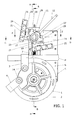
- Figure 1 shows a top plan view of the bending machine according to the present invention in an initial phase of the bending operation.
- the bending machine is of the matrix and countermatrix type. It comprises a roller-shaped matrix 1 provided with a partial circumferential groove 2, best shown in Figure 2 that is a side view being partially sectioned along the lines B-B in the top view of Figure 1 .
- the partial circumferential groove 2 is interrupted at its two ends, where respective retaining means 3, 4 is provided.
- Such retaining means 3, 4 has substantially a U-shape, the sides of the U-shape being joined at free ends thereof by a pivot 34 passing through the matrix 1.
- the matrix 1 is driven by a shaft 0 of a motor not shown in the figures.
- a casing 5 of the same bending machine is partially shown only in its upper part 6.
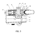
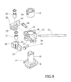
- Made on the upper part 6 of the casing 5 is a guide 7 suitable for sliding a slide 8 better shown in the side views of Figures 3 and 5 , which are partially cross-sectioned according to the lines F-F and H-H in Figure 1 , as well as in Figure 9 which is an exploded perspective view of a countermatrix support member.
- the slide 8 advances by means of a screw/nut screw coupling that is actuated by a handwheel 9 as shown in Figures 1 , 2 , 3 , 6 , 7 , and 8 , Figures 1 , 6 being top plan views of the bending machine in Figure 1 in initial and final moments of a counterclockwise bending operation, i.e. to left-hand, and Figures 7 and 8 in initial and final moments in a clockwise bending operation, i.e. to right-hand.
- the slide 8 extends upwards in a columnar element 10 best shown in Figures 2 , 3 , 5 , and 9 .
- Concentrically sleeve mounted to the columnar element 10 is a turret 11, that can rotate on the slide 8 if it is operated by a rod 12 connected to the turret 11.
- the turret 11, as shown in Figure 4 has at the bottom a pair of abutment elements 13 cooperating with a similar pair of abutment elements 14 formed on the slide 8. In this way, the turret 11 can rotate in a given arc of rotation on the slide 8.
- the turret 11 is locked on the top in order to prevent its slippage from the columnar element 10 by an abutment ring 15 arranged for a diametrical pin passing through the hole 16, as shown in particular in Figures 3 and 9 .
- the turret 11 has a pair of arms 17, 18 ( Figures 3 , 2 , 9 ) on each of which a countermatrix support member 19, 20 is pivotally mounted, each arm 17, 18 being connected to the respective countermatrix support member 19, 20 by means of a pin denoted as 21 and 22 respectively ( Figures 3 , 2 and 9 ).
- the countermatrix support members 19, 20 have an elongated shape.
- Each countermatrix support member 19, 20 has a protuberance 23 provided with a through hole for receiving the pins 21, 22, and a narrower portion 24 adapted to be connected to a countermatrix 25 and 26, respectively, to support it.
- the countermatrix support members 19, 20 being pivoted on the turret 11 are rotatable in an arc limited by a respective counteracting adjustable element 27, 28 that is threadedly coupled with related bored protrusions 29, 30 of the turret 11.
- Shown in Figure 1 is an elongated piece P to be bent that is inserted in the groove 2 of the matrix 1 and retained by retaining means 3 in the matrix 1 itself.
- the elongated piece P is ready to be counterclockwise bent, i.e. to left hand.
- the turret 11 is rotated to right hand by the rod 12 fully shown in Figure 1 , and a lower abutment element 13 thereof engages a corresponding abutment element 14 of the slide 8 ( Figure 4 ).
- the counteracting adjustable element 27 that limits the arc of rotation of the countermatrix support member 19, is in general completely screwed in the bored protrusion 29 ( Figure 1 ).
- the slide 8 is approached to the matrix 1 by the handwheel 9 ( Figure 1 ).
- the countermatrix 25 is brought in contact with the elongated piece P.
- the bending machine begins to bend to left hand ( Figure 6 ).
- the countermatrix 25 is initially moved away from the matrix 1, by simply rotating the shaft 0 in a direction opposite to the bending direction, by a sufficient angle, for example 10 degrees or less. Later, the countermatrix 25 is completely separated from the elongated piece P by rotating the turret 11 by the lever 12. At this point, by further rotating the shaft 0 to right hand, the matrix 1 is rotated in order to obtain the separation of the bent elongated piece P from the matrix 1.
- the elongated piece P to be bent is inserted in the groove 2 of the matrix 1 and retained in the retaining means of the matrix 1 itself.
- the elongated piece P is ready to be clockwise bent, i.e. to right hand.
- the turret 11 is rotated by the rod 12 fully to left hand, and its lower abutment element is counterclockwise rotated to engage the corresponding abutment element of the slide.
- the description of the adjustment of the counteracting adjustable element 28 is not repeated, being similar to that previously described.
- the slide 8 is approached to the matrix 1 by the handwheel 9 ( Figure 7 ).
- the countermatrix 26 is brought in contact with the elongated piece P.
- the bending machine begins to bend to right hand ( Figure 8 ).
- the countermatrix 26 is moved away from the matrix 1, by simply rotating the shaft 0 in a direction opposite to the bending direction, by a sufficient angle, for example 10 degrees or less, as already described for bending the elongated piece P to left hand.
- the countermatrix 26 is completely separated from the elongated P by rotating the turret 11 by the lever 12.
- the matrix 1 is rotated in order to obtain the separation of the bent elongated piece P from the matrix 1.
- Both right- and left-hand bending operations can be performed while maintaining the same position of the slide 8, and by rotating the turret 11 in the respective positions determined by the double pair of abutment elements 13 and 14.
- the matrix 1 remains mounted to the shaft 0 that is rotated to its initial positions shown in Figures 1 and 7 .
- the bending machine according to the invention allows the bending direction of an elongated piece P to be reversed simply and quickly, without the necessity of a removal of the matrix or any modification of the bending machine.
- Figure 10 is a top plan view of a variant of the matrix indicated as 31, which is different from that shown in the bending machine of the previous figures 1 to 9 .
- the rest of the bending machine is not represented as it is identical to that represented in those figures.
- an elongated element P is engaged to the matrix 31 at the beginning of a counterclockwise bending phase, i.e. to left hand.
- the matrix 31 has only one retaining means 32 for locking the elongated piece P in the vicinity of each of the two ends of the partial circumferential groove 2 of the matrix 1.
- the retaining means 32 is U-shaped, as best seen in Figure 11 , which is an exploded perspective view of the variant of matrix in Figure 10 .
- the retaining means 32 has sides 35, 36 that are provided in the vicinity of their free ends of through holes 37, 37, through which a pivot 33 can be inserted.
- the matrix 31 is provided with a hole 38 having an axis y1 parallel to the axis y of the shaft 0 of the motor.
- the axis yl of the hole 38 in the matrix 31 is equidistant between the two ends of the partial circumferential groove 2 of the matrix 31, which are indicated as 39, 40 in Figure 11 .
- the retaining means 32 is able to retain the elongated piece P for both counterclockwise bending the elongated piece P, as shown in Figure 10 , and clockwise bending it as shown in Figures 12.a-12.g , which are a plurality of top plan views of the variant of matrix in Figure 10 in successive phases of clockwise bending an elongated piece, i.e. to right-hand.
- Figures 12.a-12.g clearly show that a matrix 31 being provided with only one retaining means 32 of the elongated piece P allows its curvature by an angle greater than 180 degrees with an easy extraction of the elongated piece P at the end of the operation.
- Figure 12.a a view similar to that of Figure 10 is shown in Figure 12.a , but for clockwise bending.
- a first bending phase is shown in Figure 12.b , and, as shown in Figure 12.c , a curvature of more than 180 degrees is obtained.
- the retaining means 32 is extracted from the matrix 31; in Figure 12.e-12.g the bent elongated piece P is separated from the groove, turned upside down and removed from the matrix 31. This series of steps is valid also for the matrix having two retaining means, as previous described and illustrated in Figures 1 to 9 .
- the matrix 31 as a variant of the matrix 1 is more economic in its manufacture and has a smaller number of pieces with respect to matrix 1.
Abstract
Description
- The present invention relates to a matrix and countermatrix type bending machine for right-hand and left-hand bending an elongated piece.
- Bending machines that are able to right-hand and left-hand bend elongated workpieces such as pipes are already present on the market. A bending machine by BLM S.p.A., Cantù, Italy, owner of
U.S. Patent 6,434,993 , can be cited among the others. Said patent discloses a bending machine having a bed with body and head portions, a pair of longitudinal guides on the body portion, a pair of transverse guides on the head portion, a body carriage for holding the workpiece and being mounted on the longitudinal guides, a head carriage mounted on the transverse guides, a workpiece bending assembly mounted on the head carriage and including an elongated shaft, a pair of bending dies at opposite end regions of the shaft, and a pair of bending arms each operative for bending the workpiece against a respective bending die, and a drive for turning the bending assembly about a turning axis parallel to the longitudinal axis to position a selected one of the bending dies against the workpiece to be bent, the turning drive being mounted movable along the transverse axis with the head carriage. The machine according to the above-mentioned patent, which allows, among other, any desired both right- and left-hand bending operation, is very complex. - There are also bending machines simpler than that mentioned above which allow right and left curves to be made. Examples of such machines are described in
US-2,455,138 ,EP- 0 168 331 andUS-8,220,304 . These bending machines are of the type having a fixed matrix and a bend arm rotating around the fixed matrix. - The present invention aims instead to achieve a matrix and countermatrix type bending machine. Therein, a roller-shaped matrix being provided with a partial circumferential groove that is interrupted at its two ends, is driven by the shaft of a motor, and a countermatrix is carried by a countermatrix support member pivoted on a turret mounted on a slide which is adapted to engage the countermatrix with the matrix. In this type of bending machine, a bending in one direction and in the opposite one can be performed by turning upside down the matrix and the countermatrix. This operation is easy when matrix and countermatrix are of small size, and it becomes hard and difficult if they are of large dimensions and then heavy.
- A main purpose of the present invention is to provide a matrix and countermatrix type bending machine by which an operator can change the direction of curvature, without turning upside down the matrix and the countermatrix.
- Another object of the present invention is to provide a matrix and countermatrix type bending machine by which an operator can select and perform the curvature in one direction, and proceed with ease in the opposite direction by discharging the piece to be bent and recharging it on the same bending machine.
- Still another object of the present invention is to provide a matrix and countermatrix type bending machine by which an operator can select and perform the curvature in one direction, and proceed with ease to the curvature in the opposite direction even without discharging the piece to be bent, by virtue of a suitable choice of retaining means and the countermatrix supporting turret.
- These objects are achieved by a matrix and countermatrix type bending machine in which at least one retaining means for retaining a piece to be bent is provided on the matrix, and a double countermatrix, for right- and left-hand bending respectively is provided.
- Although matrix and countermatrix type bending machines equipped with a pair of pipe retaining means on the matrix already exist, they only serve to bend pipes of different diameter. See for example
US-3,921,424 ,US-4,546,632 andUS-5,499,521 .US-3,921,424 discloses a portable pipe bending comprising two matrices together in a single piece, each being equipped with a pipe retaining means. The pipe retaining means is hooks of different size provided at their end with corresponding grooves for retaining a pipe having a first diameter and a second diameter respectively. In order to change a pipe of a second diameter after having bent a pipe of a first diameter, the matrix needs to be turned upside down and the pipe to be attached to its retaining means. The operation for bending each pipe of different diameter occurs by clockwise rotating the matrix, and the discharge of the pipe is achieved by counterclockwise rotating the matrix. The countermatrices consist of a pair of rollers mounted on a single pivot shaft adapted to be suitably positioned depending on the diameter of the pipe to be bent. -
US-4,546,632 discloses a portable electric bender able to receive pipes of various sizes in a cone-shaped rotatable matrix. The matrix has a pair of diametrically opposite matrix portions, and each matrix portion has a plurality of curvature grooves equipped with retaining elements for retaining a pipe of different diameter. There is a similar assembly of rollers acting as a countermatrix. -
US-5,499,521 discloses a bender provided with a matrix having a plurality of concave grooves in its outer surface. The matrix is provided, in a diametrically symmetrical position, with a space adapted to receive a different retaining means depending on the pipe to be retained. A pair of rollers mounted on a frame in a swinging way act as a countermatrix. - Shortly, all the above mentioned three benders are intended to bend only in one direction, namely to right hand, pipes of different diameter and, in the case of
US-4,546,632 , also according to curves of different radius. - In this context, the technical task underlying the present invention is to propose a matrix and countermatrix type bending machine for right- and left-hand bending an elongated piece, as described in the main claim and in the claims dependent on it. An embodiment of the invention, including a variant, is described in the following detailed description, as defined in the appended dependent claims and illustrated in the accompanying drawings in which:
-
Figure 1 is a top plan view of the bending machine according to the present invention in an initial phase of the counterclockwise bending operation, i.e. to left-hand; -
Figure 2 is an enlarged side view of the bending machine shown inFigure 1 , a partial cross-section of the same being made along lines B-B; -
Figure 3 is an enlarged side view of the bending machine shown inFigure 1 , a partial cross-section of the same being made along lines F-F; -
Figure 4 is an enlarged view of the bending machine shown inFigure 2 , a partial cross-section of the same being made along lines G-G; -
Figure 5 is an enlarged side view of the bending machine shown inFigure 1 , a partial cross-section of the same being made along lines H-H; -
Figure 6 is a top plan view of the bending machine inFigure 1 in a final moment of a counter-clockwise bending operation, i.e. to left-hand; -
Figures 7 and8 are top plan views of the bending machine inFigure 1 in initial and final moments of a clockwise bending operation, i.e. to right-hand; -
Figure 9 is an exploded perspective view of a countermatrix support member of the bending machine according to the present invention; -
Figure 10 is a top plan view of a variant of the matrix with respect to that shown in the bending machine of the previous figures, in which an elongate piece at the beginning of a counterclockwise bending phase, i.e. to left-hand, is engaged; -
Figure 11 is an exploded perspective view of the variant of the matrix inFigure 10 ; and -
Figures 12.a-12.g are a plurality of top plan views of the variant of the matrix inFigure 10 in successive clockwise bending phases, i.e. to left-hand, of an elongated piece. - First, reference is made to
Figure 1 , which shows a top plan view of the bending machine according to the present invention in an initial phase of the bending operation. As above mentioned, the bending machine is of the matrix and countermatrix type. It comprises a roller-shaped matrix 1 provided with a partialcircumferential groove 2, best shown inFigure 2 that is a side view being partially sectioned along the lines B-B in the top view ofFigure 1 . The partialcircumferential groove 2 is interrupted at its two ends, where respective retaining means 3, 4 is provided. Such retaining means 3, 4, as known, has substantially a U-shape, the sides of the U-shape being joined at free ends thereof by apivot 34 passing through thematrix 1. Thematrix 1 is driven by ashaft 0 of a motor not shown in the figures. Acasing 5 of the same bending machine is partially shown only in itsupper part 6. Made on theupper part 6 of thecasing 5 is aguide 7 suitable for sliding aslide 8 better shown in the side views ofFigures 3 and5 , which are partially cross-sectioned according to the lines F-F and H-H inFigure 1 , as well as inFigure 9 which is an exploded perspective view of a countermatrix support member. - The
slide 8 advances by means of a screw/nut screw coupling that is actuated by ahandwheel 9 as shown inFigures 1 ,2 ,3 ,6 ,7 , and8 ,Figures 1 ,6 being top plan views of the bending machine inFigure 1 in initial and final moments of a counterclockwise bending operation, i.e. to left-hand, andFigures 7 and8 in initial and final moments in a clockwise bending operation, i.e. to right-hand. - The
slide 8 extends upwards in acolumnar element 10 best shown inFigures 2 ,3 ,5 , and9 . Concentrically sleeve mounted to thecolumnar element 10 is aturret 11, that can rotate on theslide 8 if it is operated by arod 12 connected to theturret 11. Theturret 11, as shown inFigure 4 , has at the bottom a pair ofabutment elements 13 cooperating with a similar pair ofabutment elements 14 formed on theslide 8. In this way, theturret 11 can rotate in a given arc of rotation on theslide 8. Theturret 11 is locked on the top in order to prevent its slippage from thecolumnar element 10 by anabutment ring 15 arranged for a diametrical pin passing through thehole 16, as shown in particular inFigures 3 and9 . Theturret 11 has a pair ofarms 17, 18 (Figures 3 ,2 ,9 ) on each of which acountermatrix support member arm countermatrix support member Figures 3 ,2 and9 ). The countermatrix supportmembers countermatrix support member protuberance 23 provided with a through hole for receiving thepins 21, 22, and anarrower portion 24 adapted to be connected to acountermatrix - The
countermatrix support members turret 11 are rotatable in an arc limited by a respective counteractingadjustable element bored protrusions turret 11. Shown inFigure 1 is an elongated piece P to be bent that is inserted in thegroove 2 of thematrix 1 and retained byretaining means 3 in thematrix 1 itself. - The elongated piece P is ready to be counterclockwise bent, i.e. to left hand. The
turret 11 is rotated to right hand by therod 12 fully shown inFigure 1 , and alower abutment element 13 thereof engages acorresponding abutment element 14 of the slide 8 (Figure 4 ). The counteractingadjustable element 27 that limits the arc of rotation of thecountermatrix support member 19, is in general completely screwed in the bored protrusion 29 (Figure 1 ). Theslide 8 is approached to thematrix 1 by the handwheel 9 (Figure 1 ). Then, thecountermatrix 25 is brought in contact with the elongated piece P. The bending machine begins to bend to left hand (Figure 6 ). After a 20 degrees bending angle, one can observe that thecountermatrix support member 19 is rotated by a given angle (not shown inFigure 6 ). At this point, the counteracting adjustable element is moved until it touches thecountermatrix support member 19. Also this operation is not shown in the drawings. - Once completed the curve to the left hand, the
countermatrix 25 is initially moved away from thematrix 1, by simply rotating theshaft 0 in a direction opposite to the bending direction, by a sufficient angle, for example 10 degrees or less. Later, thecountermatrix 25 is completely separated from the elongated piece P by rotating theturret 11 by thelever 12. At this point, by further rotating theshaft 0 to right hand, thematrix 1 is rotated in order to obtain the separation of the bent elongated piece P from thematrix 1. - In order to achieve a curve to right hand in the elongated piece P, as shown in
Figure 7 , the elongated piece P to be bent is inserted in thegroove 2 of thematrix 1 and retained in the retaining means of thematrix 1 itself. - The elongated piece P is ready to be clockwise bent, i.e. to right hand. The
turret 11 is rotated by therod 12 fully to left hand, and its lower abutment element is counterclockwise rotated to engage the corresponding abutment element of the slide. Now, the description of the adjustment of the counteractingadjustable element 28 is not repeated, being similar to that previously described. - The
slide 8 is approached to thematrix 1 by the handwheel 9 (Figure 7 ). Thecountermatrix 26 is brought in contact with the elongated piece P. The bending machine begins to bend to right hand (Figure 8 ). Once completed the curve to right hand, thecountermatrix 26 is moved away from thematrix 1, by simply rotating theshaft 0 in a direction opposite to the bending direction, by a sufficient angle, for example 10 degrees or less, as already described for bending the elongated piece P to left hand. Later, thecountermatrix 26 is completely separated from the elongated P by rotating theturret 11 by thelever 12. At this point, by further rotating theshaft 0 to left hand, thematrix 1 is rotated in order to obtain the separation of the bent elongated piece P from thematrix 1. - Both right- and left-hand bending operations can be performed while maintaining the same position of the
slide 8, and by rotating theturret 11 in the respective positions determined by the double pair ofabutment elements matrix 1 remains mounted to theshaft 0 that is rotated to its initial positions shown inFigures 1 and7 . - From foregoing it is clear that the bending machine according to the invention allows the bending direction of an elongated piece P to be reversed simply and quickly, without the necessity of a removal of the matrix or any modification of the bending machine.
- Reference is made now to
Figure 10 , which is a top plan view of a variant of the matrix indicated as 31, which is different from that shown in the bending machine of the previousfigures 1 to 9 . The rest of the bending machine is not represented as it is identical to that represented in those figures. - As shown in
figure 10 , an elongated element P is engaged to thematrix 31 at the beginning of a counterclockwise bending phase, i.e. to left hand. - The
matrix 31 has only one retaining means 32 for locking the elongated piece P in the vicinity of each of the two ends of the partialcircumferential groove 2 of thematrix 1. The retaining means 32 is U-shaped, as best seen inFigure 11 , which is an exploded perspective view of the variant of matrix inFigure 10 . - The retaining means 32 has
sides holes pivot 33 can be inserted. Thematrix 31 is provided with ahole 38 having an axis y1 parallel to the axis y of theshaft 0 of the motor. The axis yl of thehole 38 in thematrix 31 is equidistant between the two ends of the partialcircumferential groove 2 of thematrix 31, which are indicated as 39, 40 inFigure 11 . - If the
pivot 33 is inserted coaxially in thefirst hole 37 on theside 35 of the retaining means 32, in thehole 38 of thematrix 31 and in the second hole on theside 36 of the retaining means 32, the retaining means 32 is able to retain the elongated piece P for both counterclockwise bending the elongated piece P, as shown inFigure 10 , and clockwise bending it as shown inFigures 12.a-12.g , which are a plurality of top plan views of the variant of matrix inFigure 10 in successive phases of clockwise bending an elongated piece, i.e. to right-hand. -
Figures 12.a-12.g clearly show that amatrix 31 being provided with only one retaining means 32 of the elongated piece P allows its curvature by an angle greater than 180 degrees with an easy extraction of the elongated piece P at the end of the operation. - In particular, a view similar to that of
Figure 10 is shown inFigure 12.a , but for clockwise bending. A first bending phase is shown inFigure 12.b , and, as shown inFigure 12.c , a curvature of more than 180 degrees is obtained. As shown inFigure 12.d , the retaining means 32 is extracted from thematrix 31; inFigure 12.e-12.g the bent elongated piece P is separated from the groove, turned upside down and removed from thematrix 31. This series of steps is valid also for the matrix having two retaining means, as previous described and illustrated inFigures 1 to 9 . - The
matrix 31 as a variant of thematrix 1 is more economic in its manufacture and has a smaller number of pieces with respect tomatrix 1.
Claims (6)
- A matrix and countermatrix type bending machine for right-hand and left-hand bending an elongated piece (P), comprising a roller-shaped matrix (1; 31) provided with a partial circumferential groove (2) that is interrupted at its two ends, the matrix (1; 31) being driven by the shaft (0) of a motor, and a first countermatrix (25) carried by a first countermatrix support member (19) pivoted on a turret (11) mounted on a slide (8) which is operated to move the countermatrix (25) with the respect to the matrix (1; 31), the first countermatrix support member (19) and the turret (11) having axes parallel to each other, characterised in that the matrix (1; 31) has an elongated piece retaining means (3, 4; 32), and a second countermatrix (26) is carried by a second countermatrix support member (20) pivoted on the turret (11) along an axis parallel to the axis of the turret (11), which, in turn, is rotatably mounted by a lever (12) for a given arc of rotation about its axis perpendicular to the slide (8), the first or the second countermatrix (25, 26) being selectable to cooperate with the matrix (1; 31) in bending said elongated piece (P) depending on the required curvature to the right hand or the left hand of the same.
- The bending machine according to claim 1, wherein the first and second countermatrix support members (19, 20) are pivoted on the turret (11) by means of pins (21, 22) that are circumferentially spaced about 90 degrees from each other, and said given arc of rotation of the turret (11) on the slide (8) is also about 90 degrees.
- The bending machine according to claim 2, wherein the first and second countermatrix support members (19, 20) both being pivoted on the turret (11) are rotatable in an arc of rotation limited by a respective adjustable counteracting element (27, 28) that is connected to the turret (11) with a threaded coupling.
- The bending machine according to claim 2, wherein said given arc of rotation of the turret (11) on the slide (8) is limited by means of a double pair of cooperating abutment elements (13, 14) formed on the slide (8) and on a lower part of the turret (11), respectively, the first pair of abutment elements (13, 14) serving for left-hand bending and the second pair of abutment elements (13, 14) serving for right-hand bending.
- The bending machine according to claim 1, wherein the matrix (1) has an elongated piece retaining means (3, 4) at each of said two ends of its partial circumferential groove (2), each elongated piece retaining means (3, 4) being U-shaped, with sides of its U-shape being joined at the free ends thereof by a pivot (34) passing through the matrix (1).
- The bending machine according to claim 1, wherein the matrix (31) has only one elongated piece retaining means (32) adapted to lock the elongated piece (P) near the one or the other end of its partial circumferential groove (2), said elongated piece retaining means (32) being U-shaped, with sides (35, 36) of its U-shape being joined at the free ends thereof by a pivot (33) passing through both said sides (35, 36) and said matrix (31) in concentrical holes (37, 37, 38) having axis (y1) parallel to the axis (y) of the shaft (0) of the motor and equi-spaced between said ends of the partial circumferential groove (2) of said matrix (31).
Priority Applications (9)
| Application Number | Priority Date | Filing Date | Title |
|---|---|---|---|
| PL14425014T PL2799158T3 (en) | 2013-05-02 | 2014-02-13 | Matrix and countermatrix type bending machine for right-hand and left-hand bending an elongated piece |
| CA2850846A CA2850846C (en) | 2013-05-02 | 2014-04-28 | Die and counter-die type bending machine for right-hand and left-hand bending an elongated piece |
| RU2014117617/02A RU2569616C1 (en) | 2013-05-02 | 2014-04-29 | Bending machine with mould and male mould for right-side and left-side bending of extended detail |
| MX2014005230A MX357439B (en) | 2013-05-02 | 2014-04-30 | Matrix and countermatrix type bending machine for right-hand and left-hand bending an elongated piece. |
| BR102014010400A BR102014010400A2 (en) | 2013-05-02 | 2014-04-30 | mold-type folding machine and counter-mold to bend an elongated piece to the right and left |
| US14/267,047 US9878361B2 (en) | 2013-05-02 | 2014-05-01 | Die and counter-die type bending machine for right-hand and left-hand bending an elongated piece |
| JP2014094499A JP5889952B2 (en) | 2013-05-02 | 2014-05-01 | Die and counter die type bending machine for bending elongated pieces clockwise and counterclockwise |
| KR1020140053266A KR101636684B1 (en) | 2013-05-02 | 2014-05-02 | Die and counter-die type bending machine for right-hand and left-hand bending an elongated piece |
| CN201410246716.XA CN104289566B (en) | 2013-05-02 | 2014-05-04 | For adding the bending machine of opposition mould type to the mould of right and left curved elongated workpiece |
Applications Claiming Priority (1)
| Application Number | Priority Date | Filing Date | Title |
|---|---|---|---|
| IT000259A ITRM20130259A1 (en) | 2013-05-02 | 2013-05-02 | BENDING MACHINE OF THE MATRIX AND COUNTERMATCHING TYPE TO TURN RIGHT AND LEFT A PIECE STRETCHED |
Publications (2)
| Publication Number | Publication Date |
|---|---|
| EP2799158A1 true EP2799158A1 (en) | 2014-11-05 |
| EP2799158B1 EP2799158B1 (en) | 2015-09-30 |
Family
ID=48579360
Family Applications (1)
| Application Number | Title | Priority Date | Filing Date |
|---|---|---|---|
| EP14425014.9A Active EP2799158B1 (en) | 2013-05-02 | 2014-02-13 | Matrix and countermatrix type bending machine for right-hand and left-hand bending an elongated piece |
Country Status (13)
| Country | Link |
|---|---|
| US (1) | US9878361B2 (en) |
| EP (1) | EP2799158B1 (en) |
| JP (1) | JP5889952B2 (en) |
| KR (1) | KR101636684B1 (en) |
| CN (1) | CN104289566B (en) |
| BR (1) | BR102014010400A2 (en) |
| CA (1) | CA2850846C (en) |
| ES (1) | ES2561167T3 (en) |
| IT (1) | ITRM20130259A1 (en) |
| MX (1) | MX357439B (en) |
| PL (1) | PL2799158T3 (en) |
| PT (1) | PT2799158E (en) |
| RU (1) | RU2569616C1 (en) |
Cited By (4)
| Publication number | Priority date | Publication date | Assignee | Title |
|---|---|---|---|---|
| WO2016157022A1 (en) * | 2015-04-02 | 2016-10-06 | Massaro Libero Angelo | Multipurpose machine for bending metal tubes, both small and large |
| ITUB20153370A1 (en) * | 2015-09-03 | 2017-03-03 | C B C S R L | PERFECT SLEDGE FOR A BENDING DEVICE FOR LENGTHED TUBULAR ELEMENTS |
| ITUA20161931A1 (en) * | 2016-03-23 | 2017-09-23 | Crippa Spa | Device for the bending of a filiform material |
| WO2020100048A1 (en) * | 2018-11-16 | 2020-05-22 | Cml International S.P.A. | Machine for bending an elongated workpiece without wrinkling |
Families Citing this family (9)
| Publication number | Priority date | Publication date | Assignee | Title |
|---|---|---|---|---|
| CN106493258A (en) * | 2016-11-08 | 2017-03-15 | 周朝敬 | A kind of angle bending apparatus and its using method for cable |
| DE102017117979A1 (en) | 2017-08-08 | 2019-02-14 | Wafios Aktiengesellschaft | Bending machine for bending rod-shaped or tubular workpieces |
| CN107913927A (en) * | 2017-09-18 | 2018-04-17 | 浙江长兴和良智能装备有限公司 | A kind of bending machine |
| US11484929B2 (en) * | 2017-12-11 | 2022-11-01 | Cml International S.P.A. | Hydraulically operated rotary pipe bending machine |
| CN109500288B (en) * | 2018-12-27 | 2024-02-13 | 上海建工五建集团有限公司 | Portable steel bar bending tool and use method thereof |
| CN112742923B (en) * | 2020-12-21 | 2023-04-18 | 河南质量工程职业学院 | Pipe bending device for building construction and using method thereof |
| CN113619087B (en) * | 2021-07-07 | 2023-09-29 | 岳阳高澜节能装备制造有限公司 | Pipeline bending device capable of preventing port from deforming |
| CN113523043B (en) * | 2021-07-20 | 2022-12-02 | 中国建筑第八工程局有限公司 | Workpiece bending apparatus and workpiece bending method |
| CN114425576A (en) * | 2021-12-24 | 2022-05-03 | 安徽扬天金塑新能源装备有限公司 | Multidirectional bending pipe bending device |
Citations (8)
| Publication number | Priority date | Publication date | Assignee | Title |
|---|---|---|---|---|
| US2455138A (en) | 1946-08-16 | 1948-11-30 | George C H Perkins | Pivoted bender with reversible clamp and former |
| US3921424A (en) | 1974-09-18 | 1975-11-25 | Greenlee Bros & Co | Portable electric driven conduit bender |
| US4546632A (en) | 1982-04-14 | 1985-10-15 | Applied Power Inc. | Portable conduit bending apparatus |
| EP0168331A2 (en) | 1984-07-10 | 1986-01-15 | Eaton Leonard Picot S.A. | Machine for bending of tubes, bars or profiles |
| EP0445081A2 (en) * | 1990-03-02 | 1991-09-04 | C.M.L. COSTRUZIONI MECCANICHE LIRI S.r.l. | Pipe bending machine with cantilevered bending head, with interchangeable multifunction tool, and being programmable by means of a computerized unit |
| US5499521A (en) | 1994-03-08 | 1996-03-19 | Crawford Fitting Company | Tube bender apparatus |
| US6434993B1 (en) | 2001-01-30 | 2002-08-20 | Blm S.P.A. | Bending machine for bending threadlike material such as tubes, rods profiles or metal wire |
| US8220304B2 (en) | 2005-10-28 | 2012-07-17 | Numalliance | Machine for cambering, forming, folding or bending bars, wires or extruded shapes |
Family Cites Families (24)
| Publication number | Priority date | Publication date | Assignee | Title |
|---|---|---|---|---|
| GB311720A (en) * | 1928-02-15 | 1929-05-15 | James Ernest Jackson | Improvements in pipe-bending machines |
| US1919839A (en) * | 1930-03-02 | 1933-07-25 | Hilgers Franz | Pipe-bending machine |
| US2171907A (en) * | 1936-08-05 | 1939-09-05 | Imp Brass Mfg Co | Tube bender |
| US3236082A (en) * | 1961-07-24 | 1966-02-22 | Crawford Fitting Co | Tube bending tools |
| US3448602A (en) * | 1965-10-24 | 1969-06-10 | Parker Hannifin Corp | Hand held tube bender |
| DE2626202C2 (en) * | 1976-06-11 | 1992-10-29 | Rigobert Dipl.-Ing. 5000 Köln Schwarze | Tube bending machine |
| JPS6480836A (en) * | 1987-09-24 | 1989-03-27 | Kaneko Agricult Machinery | Moisture measuring instrument for sample grain |
| JPH02263521A (en) * | 1989-04-05 | 1990-10-26 | Hitachi Ltd | Pipe bender |
| DE4106230A1 (en) * | 1991-02-25 | 1992-08-27 | Hans Werner Klieme | Bending hollow metal sections - using machine with grooves in bending roller and support bar to match section contour |
| DE9316052U1 (en) * | 1993-10-21 | 1994-01-13 | Schwarze Rigobert | Pipe bending machine |
| IT1294256B1 (en) * | 1997-08-29 | 1999-03-24 | Cml Costr Mecc Liri Srl | UNIVERSAL BENDING MACHINE WITH FIXED AND VARIABLE RAYS |
| JPH11138215A (en) * | 1997-11-06 | 1999-05-25 | Yamamoto Suiatsu Kogyosho:Kk | Pipe bender |
| JP4592843B2 (en) * | 1999-08-23 | 2010-12-08 | 株式会社オプトン | Bending device |
| JP2004314222A (en) * | 2003-04-15 | 2004-11-11 | Imao Corporation:Kk | Clamping device |
| ITRM20040402A1 (en) * | 2004-08-05 | 2004-11-05 | Cml Int Spa | VICE FOR LOCKING AN ELONGATED ELEMENT TO BE CURVED ON A BENDING MACHINE MATRIX. |
| TWI273935B (en) * | 2005-01-25 | 2007-02-21 | Cml Int Spa | Bending device for bending machine |
| ITRM20050035A1 (en) * | 2005-01-25 | 2006-07-26 | Cml Int Spa | BENDING HEAD FOR BENDING MACHINE. |
| ATE397501T1 (en) * | 2005-03-08 | 2008-06-15 | Wafios Ag | BENDING DEVICE FOR BAR AND TUBE-SHAPED WORKPIECES AND Wrinkle Smoothing Arrangement |
| US7100414B1 (en) * | 2005-09-16 | 2006-09-05 | Mckay Acquisition, Inc. | Adjustable cam assembly for mounting a pressure die to a pipe bending machine |
| US7380430B1 (en) * | 2007-03-16 | 2008-06-03 | Christopher J. Rusch | Rotary draw tube bender |
| ITRM20070483A1 (en) * | 2007-09-17 | 2009-03-18 | Cml Int Spa | CURVATURI MACHINE WITH ANIMA HAVING A CARRYING STRUCTURE PARTICULARLY RESISTANT TO LOAVORATION STRESSES |
| IT1391476B1 (en) * | 2008-10-28 | 2011-12-23 | Cml Int Spa | CURVATURI MACHINE WITH PERFECT TRANSMISSION OF THE MOTORCYCLE TO THE MATRIX |
| ATE528082T1 (en) * | 2009-01-16 | 2011-10-15 | Wafios Ag | ROTARY PULL BENDING TOOL WITH ECCENTRIC CLAMP |
| CN102601183A (en) * | 2012-03-19 | 2012-07-25 | 昆山长运电子工业有限公司 | Multi-angle multi-diameter workpiece bending device |
-
2013
- 2013-05-02 IT IT000259A patent/ITRM20130259A1/en unknown
-
2014
- 2014-02-13 EP EP14425014.9A patent/EP2799158B1/en active Active
- 2014-02-13 PT PT144250149T patent/PT2799158E/en unknown
- 2014-02-13 ES ES14425014.9T patent/ES2561167T3/en active Active
- 2014-02-13 PL PL14425014T patent/PL2799158T3/en unknown
- 2014-04-28 CA CA2850846A patent/CA2850846C/en active Active
- 2014-04-29 RU RU2014117617/02A patent/RU2569616C1/en active IP Right Revival
- 2014-04-30 BR BR102014010400A patent/BR102014010400A2/en not_active Application Discontinuation
- 2014-04-30 MX MX2014005230A patent/MX357439B/en active IP Right Grant
- 2014-05-01 JP JP2014094499A patent/JP5889952B2/en active Active
- 2014-05-01 US US14/267,047 patent/US9878361B2/en active Active - Reinstated
- 2014-05-02 KR KR1020140053266A patent/KR101636684B1/en active IP Right Grant
- 2014-05-04 CN CN201410246716.XA patent/CN104289566B/en active Active
Patent Citations (8)
| Publication number | Priority date | Publication date | Assignee | Title |
|---|---|---|---|---|
| US2455138A (en) | 1946-08-16 | 1948-11-30 | George C H Perkins | Pivoted bender with reversible clamp and former |
| US3921424A (en) | 1974-09-18 | 1975-11-25 | Greenlee Bros & Co | Portable electric driven conduit bender |
| US4546632A (en) | 1982-04-14 | 1985-10-15 | Applied Power Inc. | Portable conduit bending apparatus |
| EP0168331A2 (en) | 1984-07-10 | 1986-01-15 | Eaton Leonard Picot S.A. | Machine for bending of tubes, bars or profiles |
| EP0445081A2 (en) * | 1990-03-02 | 1991-09-04 | C.M.L. COSTRUZIONI MECCANICHE LIRI S.r.l. | Pipe bending machine with cantilevered bending head, with interchangeable multifunction tool, and being programmable by means of a computerized unit |
| US5499521A (en) | 1994-03-08 | 1996-03-19 | Crawford Fitting Company | Tube bender apparatus |
| US6434993B1 (en) | 2001-01-30 | 2002-08-20 | Blm S.P.A. | Bending machine for bending threadlike material such as tubes, rods profiles or metal wire |
| US8220304B2 (en) | 2005-10-28 | 2012-07-17 | Numalliance | Machine for cambering, forming, folding or bending bars, wires or extruded shapes |
Cited By (8)
| Publication number | Priority date | Publication date | Assignee | Title |
|---|---|---|---|---|
| WO2016157022A1 (en) * | 2015-04-02 | 2016-10-06 | Massaro Libero Angelo | Multipurpose machine for bending metal tubes, both small and large |
| US20180078984A1 (en) * | 2015-04-02 | 2018-03-22 | Libero Angelo MASSARO | Multipurpose machine for bending metal tubes, both small and large |
| ITUB20153370A1 (en) * | 2015-09-03 | 2017-03-03 | C B C S R L | PERFECT SLEDGE FOR A BENDING DEVICE FOR LENGTHED TUBULAR ELEMENTS |
| EP3141311A1 (en) * | 2015-09-03 | 2017-03-15 | C.B.C. S.r.l. | Enhanced slide for a bending machine for elongated tubular elements |
| ITUA20161931A1 (en) * | 2016-03-23 | 2017-09-23 | Crippa Spa | Device for the bending of a filiform material |
| EP3228397A1 (en) * | 2016-03-23 | 2017-10-11 | Crippa S.P.A. | Device for bending a thread-like material |
| WO2020100048A1 (en) * | 2018-11-16 | 2020-05-22 | Cml International S.P.A. | Machine for bending an elongated workpiece without wrinkling |
| US11745244B2 (en) | 2018-11-16 | 2023-09-05 | Cml International S.P.A. | Machine for bending an elongated workpiece without wrinkling |
Also Published As
| Publication number | Publication date |
|---|---|
| JP2014223673A (en) | 2014-12-04 |
| CN104289566A (en) | 2015-01-21 |
| JP5889952B2 (en) | 2016-03-22 |
| US20140326033A1 (en) | 2014-11-06 |
| US9878361B2 (en) | 2018-01-30 |
| ITRM20130259A1 (en) | 2014-11-03 |
| BR102014010400A2 (en) | 2015-12-29 |
| CN104289566B (en) | 2016-09-07 |
| CA2850846A1 (en) | 2014-11-02 |
| KR20140131282A (en) | 2014-11-12 |
| MX357439B (en) | 2018-07-10 |
| RU2014117617A (en) | 2015-11-10 |
| RU2569616C1 (en) | 2015-11-27 |
| KR101636684B1 (en) | 2016-07-07 |
| PT2799158E (en) | 2016-01-27 |
| EP2799158B1 (en) | 2015-09-30 |
| CA2850846C (en) | 2018-06-12 |
| PL2799158T3 (en) | 2016-08-31 |
| MX2014005230A (en) | 2015-04-29 |
| ES2561167T3 (en) | 2016-02-24 |
Similar Documents
| Publication | Publication Date | Title |
|---|---|---|
| EP2799158B1 (en) | Matrix and countermatrix type bending machine for right-hand and left-hand bending an elongated piece | |
| US3040800A (en) | Tube flaring tool | |
| EP3177414B1 (en) | Bending head, especially for an automatic bending machine | |
| CN208083266U (en) | A kind of bend punching die of reinforcing bar | |
| US10189069B1 (en) | Portable tube bender | |
| EP3315331B1 (en) | Tyre changing machine | |
| EP3315251B1 (en) | Electrospindle for automatic tool changing and machining center with automatic tool changing device | |
| EP2977324B1 (en) | Dispensing apparatus, method of dispensing, capping apparatus and method of capping | |
| KR101895320B1 (en) | pipe bending machine | |
| JP6159452B2 (en) | Wire bending machine | |
| WO2015033255A1 (en) | Positioner for tubes | |
| RU2670593C2 (en) | Inward flanging assembly | |
| EP2014382A1 (en) | Tube bending machine | |
| JP5894136B2 (en) | Processing unit and processing equipment | |
| EP1579930B1 (en) | Bending device for bars | |
| US2569544A (en) | Portable bending machine | |
| JP2008036675A (en) | Bending apparatus | |
| EP2982455A1 (en) | Apparatus and method for bending tubular components | |
| CN106111752A (en) | A kind of can the straight plate of bending and the device of steel pipe | |
| CN104999401A (en) | Spiral and rapid ratchet wrench | |
| CN107671206B (en) | Reinforcement bar strengthener | |
| CN207642191U (en) | A kind of hydraulic steel bar bender | |
| CN210966500U (en) | Bending device of bending machine | |
| CN102513412B (en) | Broach straightening device | |
| JP6682359B2 (en) | Wire bending equipment |
Legal Events
| Date | Code | Title | Description |
|---|---|---|---|
| PUAI | Public reference made under article 153(3) epc to a published international application that has entered the european phase |
Free format text: ORIGINAL CODE: 0009012 |
|
| 17P | Request for examination filed |
Effective date: 20140213 |
|
| AK | Designated contracting states |
Kind code of ref document: A1 Designated state(s): AL AT BE BG CH CY CZ DE DK EE ES FI FR GB GR HR HU IE IS IT LI LT LU LV MC MK MT NL NO PL PT RO RS SE SI SK SM TR |
|
| AX | Request for extension of the european patent |
Extension state: BA ME |
|
| R17P | Request for examination filed (corrected) |
Effective date: 20141009 |
|
| RBV | Designated contracting states (corrected) |
Designated state(s): AL AT BE BG CH CY CZ DE DK EE ES FI FR GB GR HR HU IE IS IT LI LT LU LV MC MK MT NL NO PL PT RO RS SE SI SK SM TR |
|
| GRAP | Despatch of communication of intention to grant a patent |
Free format text: ORIGINAL CODE: EPIDOSNIGR1 |
|
| RIC1 | Information provided on ipc code assigned before grant |
Ipc: B21D 7/024 20060101AFI20150409BHEP |
|
| INTG | Intention to grant announced |
Effective date: 20150424 |
|
| GRAS | Grant fee paid |
Free format text: ORIGINAL CODE: EPIDOSNIGR3 |
|
| GRAA | (expected) grant |
Free format text: ORIGINAL CODE: 0009210 |
|
| AK | Designated contracting states |
Kind code of ref document: B1 Designated state(s): AL AT BE BG CH CY CZ DE DK EE ES FI FR GB GR HR HU IE IS IT LI LT LU LV MC MK MT NL NO PL PT RO RS SE SI SK SM TR |
|
| REG | Reference to a national code |
Ref country code: CH Ref legal event code: EP Ref country code: GB Ref legal event code: FG4D |
|
| REG | Reference to a national code |
Ref country code: AT Ref legal event code: REF Ref document number: 752086 Country of ref document: AT Kind code of ref document: T Effective date: 20151015 |
|
| REG | Reference to a national code |
Ref country code: IE Ref legal event code: FG4D |
|
| REG | Reference to a national code |
Ref country code: DE Ref legal event code: R096 Ref document number: 602014000289 Country of ref document: DE |
|
| REG | Reference to a national code |
Ref country code: PT Ref legal event code: SC4A Free format text: AVAILABILITY OF NATIONAL TRANSLATION Effective date: 20151228 |
|
| PG25 | Lapsed in a contracting state [announced via postgrant information from national office to epo] |
Ref country code: GR Free format text: LAPSE BECAUSE OF FAILURE TO SUBMIT A TRANSLATION OF THE DESCRIPTION OR TO PAY THE FEE WITHIN THE PRESCRIBED TIME-LIMIT Effective date: 20151231 Ref country code: LT Free format text: LAPSE BECAUSE OF FAILURE TO SUBMIT A TRANSLATION OF THE DESCRIPTION OR TO PAY THE FEE WITHIN THE PRESCRIBED TIME-LIMIT Effective date: 20150930 Ref country code: FI Free format text: LAPSE BECAUSE OF FAILURE TO SUBMIT A TRANSLATION OF THE DESCRIPTION OR TO PAY THE FEE WITHIN THE PRESCRIBED TIME-LIMIT Effective date: 20150930 Ref country code: NO Free format text: LAPSE BECAUSE OF FAILURE TO SUBMIT A TRANSLATION OF THE DESCRIPTION OR TO PAY THE FEE WITHIN THE PRESCRIBED TIME-LIMIT Effective date: 20151230 Ref country code: LV Free format text: LAPSE BECAUSE OF FAILURE TO SUBMIT A TRANSLATION OF THE DESCRIPTION OR TO PAY THE FEE WITHIN THE PRESCRIBED TIME-LIMIT Effective date: 20150930 |
|
| REG | Reference to a national code |
Ref country code: NL Ref legal event code: MP Effective date: 20150930 |
|
| REG | Reference to a national code |
Ref country code: LT Ref legal event code: MG4D |
|
| REG | Reference to a national code |
Ref country code: AT Ref legal event code: MK05 Ref document number: 752086 Country of ref document: AT Kind code of ref document: T Effective date: 20150930 |
|
| REG | Reference to a national code |
Ref country code: ES Ref legal event code: FG2A Ref document number: 2561167 Country of ref document: ES Kind code of ref document: T3 Effective date: 20160224 |
|
| PG25 | Lapsed in a contracting state [announced via postgrant information from national office to epo] |
Ref country code: RS Free format text: LAPSE BECAUSE OF FAILURE TO SUBMIT A TRANSLATION OF THE DESCRIPTION OR TO PAY THE FEE WITHIN THE PRESCRIBED TIME-LIMIT Effective date: 20150930 Ref country code: HR Free format text: LAPSE BECAUSE OF FAILURE TO SUBMIT A TRANSLATION OF THE DESCRIPTION OR TO PAY THE FEE WITHIN THE PRESCRIBED TIME-LIMIT Effective date: 20150930 Ref country code: SE Free format text: LAPSE BECAUSE OF FAILURE TO SUBMIT A TRANSLATION OF THE DESCRIPTION OR TO PAY THE FEE WITHIN THE PRESCRIBED TIME-LIMIT Effective date: 20150930 |
|
| REG | Reference to a national code |
Ref country code: FR Ref legal event code: PLFP Year of fee payment: 3 |
|
| PG25 | Lapsed in a contracting state [announced via postgrant information from national office to epo] |
Ref country code: EE Free format text: LAPSE BECAUSE OF FAILURE TO SUBMIT A TRANSLATION OF THE DESCRIPTION OR TO PAY THE FEE WITHIN THE PRESCRIBED TIME-LIMIT Effective date: 20150930 Ref country code: IS Free format text: LAPSE BECAUSE OF FAILURE TO SUBMIT A TRANSLATION OF THE DESCRIPTION OR TO PAY THE FEE WITHIN THE PRESCRIBED TIME-LIMIT Effective date: 20160130 Ref country code: IT Free format text: LAPSE BECAUSE OF FAILURE TO SUBMIT A TRANSLATION OF THE DESCRIPTION OR TO PAY THE FEE WITHIN THE PRESCRIBED TIME-LIMIT Effective date: 20150930 Ref country code: CZ Free format text: LAPSE BECAUSE OF FAILURE TO SUBMIT A TRANSLATION OF THE DESCRIPTION OR TO PAY THE FEE WITHIN THE PRESCRIBED TIME-LIMIT Effective date: 20150930 Ref country code: NL Free format text: LAPSE BECAUSE OF FAILURE TO SUBMIT A TRANSLATION OF THE DESCRIPTION OR TO PAY THE FEE WITHIN THE PRESCRIBED TIME-LIMIT Effective date: 20150930 Ref country code: SK Free format text: LAPSE BECAUSE OF FAILURE TO SUBMIT A TRANSLATION OF THE DESCRIPTION OR TO PAY THE FEE WITHIN THE PRESCRIBED TIME-LIMIT Effective date: 20150930 |
|
| PG25 | Lapsed in a contracting state [announced via postgrant information from national office to epo] |
Ref country code: AT Free format text: LAPSE BECAUSE OF FAILURE TO SUBMIT A TRANSLATION OF THE DESCRIPTION OR TO PAY THE FEE WITHIN THE PRESCRIBED TIME-LIMIT Effective date: 20150930 Ref country code: BE Free format text: LAPSE BECAUSE OF NON-PAYMENT OF DUE FEES Effective date: 20160229 Ref country code: RO Free format text: LAPSE BECAUSE OF FAILURE TO SUBMIT A TRANSLATION OF THE DESCRIPTION OR TO PAY THE FEE WITHIN THE PRESCRIBED TIME-LIMIT Effective date: 20150930 |
|
| REG | Reference to a national code |
Ref country code: DE Ref legal event code: R097 Ref document number: 602014000289 Country of ref document: DE |
|
| PLBE | No opposition filed within time limit |
Free format text: ORIGINAL CODE: 0009261 |
|
| STAA | Information on the status of an ep patent application or granted ep patent |
Free format text: STATUS: NO OPPOSITION FILED WITHIN TIME LIMIT |
|
| PG25 | Lapsed in a contracting state [announced via postgrant information from national office to epo] |
Ref country code: DK Free format text: LAPSE BECAUSE OF FAILURE TO SUBMIT A TRANSLATION OF THE DESCRIPTION OR TO PAY THE FEE WITHIN THE PRESCRIBED TIME-LIMIT Effective date: 20150930 |
|
| REG | Reference to a national code |
Ref country code: DE Ref legal event code: R119 Ref document number: 602014000289 Country of ref document: DE |
|
| REG | Reference to a national code |
Ref country code: DE Ref legal event code: R073 Ref document number: 602014000289 Country of ref document: DE |
|
| 26N | No opposition filed |
Effective date: 20160701 |
|
| PG25 | Lapsed in a contracting state [announced via postgrant information from national office to epo] |
Ref country code: LU Free format text: LAPSE BECAUSE OF FAILURE TO SUBMIT A TRANSLATION OF THE DESCRIPTION OR TO PAY THE FEE WITHIN THE PRESCRIBED TIME-LIMIT Effective date: 20160213 Ref country code: MC Free format text: LAPSE BECAUSE OF FAILURE TO SUBMIT A TRANSLATION OF THE DESCRIPTION OR TO PAY THE FEE WITHIN THE PRESCRIBED TIME-LIMIT Effective date: 20150930 |
|
| PG25 | Lapsed in a contracting state [announced via postgrant information from national office to epo] |
Ref country code: SI Free format text: LAPSE BECAUSE OF FAILURE TO SUBMIT A TRANSLATION OF THE DESCRIPTION OR TO PAY THE FEE WITHIN THE PRESCRIBED TIME-LIMIT Effective date: 20150930 |
|
| REG | Reference to a national code |
Ref country code: IE Ref legal event code: MM4A |
|
| PG25 | Lapsed in a contracting state [announced via postgrant information from national office to epo] |
Ref country code: BE Free format text: LAPSE BECAUSE OF FAILURE TO SUBMIT A TRANSLATION OF THE DESCRIPTION OR TO PAY THE FEE WITHIN THE PRESCRIBED TIME-LIMIT Effective date: 20150930 |
|
| PG25 | Lapsed in a contracting state [announced via postgrant information from national office to epo] |
Ref country code: IE Free format text: LAPSE BECAUSE OF NON-PAYMENT OF DUE FEES Effective date: 20160213 Ref country code: DE Free format text: LAPSE BECAUSE OF NON-PAYMENT OF DUE FEES Effective date: 20160901 |
|
| PG25 | Lapsed in a contracting state [announced via postgrant information from national office to epo] |
Ref country code: PT Free format text: LAPSE BECAUSE OF NON-PAYMENT OF DUE FEES Effective date: 20161114 |
|
| REG | Reference to a national code |
Ref country code: FR Ref legal event code: PLFP Year of fee payment: 4 |
|
| REG | Reference to a national code |
Ref country code: DE Ref legal event code: R124 Ref document number: 602014000289 Country of ref document: DE |
|
| PG25 | Lapsed in a contracting state [announced via postgrant information from national office to epo] |
Ref country code: MT Free format text: LAPSE BECAUSE OF FAILURE TO SUBMIT A TRANSLATION OF THE DESCRIPTION OR TO PAY THE FEE WITHIN THE PRESCRIBED TIME-LIMIT Effective date: 20150930 |
|
| REG | Reference to a national code |
Ref country code: CH Ref legal event code: PL |
|
| PG25 | Lapsed in a contracting state [announced via postgrant information from national office to epo] |
Ref country code: LI Free format text: LAPSE BECAUSE OF NON-PAYMENT OF DUE FEES Effective date: 20170228 Ref country code: CH Free format text: LAPSE BECAUSE OF NON-PAYMENT OF DUE FEES Effective date: 20170228 |
|
| PG25 | Lapsed in a contracting state [announced via postgrant information from national office to epo] |
Ref country code: SM Free format text: LAPSE BECAUSE OF FAILURE TO SUBMIT A TRANSLATION OF THE DESCRIPTION OR TO PAY THE FEE WITHIN THE PRESCRIBED TIME-LIMIT Effective date: 20150930 Ref country code: HU Free format text: LAPSE BECAUSE OF FAILURE TO SUBMIT A TRANSLATION OF THE DESCRIPTION OR TO PAY THE FEE WITHIN THE PRESCRIBED TIME-LIMIT; INVALID AB INITIO Effective date: 20140213 |
|
| PG25 | Lapsed in a contracting state [announced via postgrant information from national office to epo] |
Ref country code: MK Free format text: LAPSE BECAUSE OF FAILURE TO SUBMIT A TRANSLATION OF THE DESCRIPTION OR TO PAY THE FEE WITHIN THE PRESCRIBED TIME-LIMIT Effective date: 20150930 Ref country code: MT Free format text: LAPSE BECAUSE OF FAILURE TO SUBMIT A TRANSLATION OF THE DESCRIPTION OR TO PAY THE FEE WITHIN THE PRESCRIBED TIME-LIMIT Effective date: 20160229 Ref country code: CY Free format text: LAPSE BECAUSE OF FAILURE TO SUBMIT A TRANSLATION OF THE DESCRIPTION OR TO PAY THE FEE WITHIN THE PRESCRIBED TIME-LIMIT Effective date: 20150930 |
|
| REG | Reference to a national code |
Ref country code: FR Ref legal event code: PLFP Year of fee payment: 5 |
|
| PG25 | Lapsed in a contracting state [announced via postgrant information from national office to epo] |
Ref country code: BG Free format text: LAPSE BECAUSE OF FAILURE TO SUBMIT A TRANSLATION OF THE DESCRIPTION OR TO PAY THE FEE WITHIN THE PRESCRIBED TIME-LIMIT Effective date: 20150930 |
|
| PG25 | Lapsed in a contracting state [announced via postgrant information from national office to epo] |
Ref country code: AL Free format text: LAPSE BECAUSE OF FAILURE TO SUBMIT A TRANSLATION OF THE DESCRIPTION OR TO PAY THE FEE WITHIN THE PRESCRIBED TIME-LIMIT Effective date: 20150930 |
|
| PGFP | Annual fee paid to national office [announced via postgrant information from national office to epo] |
Ref country code: TR Payment date: 20190213 Year of fee payment: 6 |
|
| PGFP | Annual fee paid to national office [announced via postgrant information from national office to epo] |
Ref country code: PL Payment date: 20210215 Year of fee payment: 8 |
|
| PG25 | Lapsed in a contracting state [announced via postgrant information from national office to epo] |
Ref country code: TR Free format text: LAPSE BECAUSE OF NON-PAYMENT OF DUE FEES Effective date: 20200213 |
|
| PGFP | Annual fee paid to national office [announced via postgrant information from national office to epo] |
Ref country code: FR Payment date: 20230227 Year of fee payment: 10 |
|
| PGFP | Annual fee paid to national office [announced via postgrant information from national office to epo] |
Ref country code: PT Payment date: 20230301 Year of fee payment: 10 Ref country code: GB Payment date: 20230331 Year of fee payment: 10 |
|
| PGFP | Annual fee paid to national office [announced via postgrant information from national office to epo] |
Ref country code: ES Payment date: 20230503 Year of fee payment: 10 |