EP2745801A1 - Method for producing a dental restoration part, and dental oven - Google Patents
Method for producing a dental restoration part, and dental oven Download PDFInfo
- Publication number
- EP2745801A1 EP2745801A1 EP12197844.9A EP12197844A EP2745801A1 EP 2745801 A1 EP2745801 A1 EP 2745801A1 EP 12197844 A EP12197844 A EP 12197844A EP 2745801 A1 EP2745801 A1 EP 2745801A1
- Authority
- EP
- European Patent Office
- Prior art keywords
- layer
- dental restoration
- dental
- restoration part
- image
- Prior art date
- Legal status (The legal status is an assumption and is not a legal conclusion. Google has not performed a legal analysis and makes no representation as to the accuracy of the status listed.)
- Granted
Links
- 238000004519 manufacturing process Methods 0.000 title claims abstract description 12
- 238000000034 method Methods 0.000 claims abstract description 25
- 238000003860 storage Methods 0.000 claims description 8
- 238000006116 polymerization reaction Methods 0.000 claims description 6
- 230000000379 polymerizing effect Effects 0.000 claims description 3
- 238000001514 detection method Methods 0.000 claims description 2
- 239000011521 glass Substances 0.000 claims description 2
- 238000010304 firing Methods 0.000 claims 3
- 238000003825 pressing Methods 0.000 claims 2
- 238000012790 confirmation Methods 0.000 claims 1
- 239000005548 dental material Substances 0.000 claims 1
- 238000005286 illumination Methods 0.000 claims 1
- 238000001454 recorded image Methods 0.000 claims 1
- 239000000463 material Substances 0.000 description 7
- 238000010276 construction Methods 0.000 description 2
- 210000003298 dental enamel Anatomy 0.000 description 2
- 230000015572 biosynthetic process Effects 0.000 description 1
- 239000000919 ceramic Substances 0.000 description 1
- 239000002131 composite material Substances 0.000 description 1
- 238000012937 correction Methods 0.000 description 1
- 210000004268 dentin Anatomy 0.000 description 1
- 238000011161 development Methods 0.000 description 1
- 230000018109 developmental process Effects 0.000 description 1
- 230000002349 favourable effect Effects 0.000 description 1
- 238000010191 image analysis Methods 0.000 description 1
- 230000003993 interaction Effects 0.000 description 1
- 239000007937 lozenge Substances 0.000 description 1
- 230000003287 optical effect Effects 0.000 description 1
- 238000002360 preparation method Methods 0.000 description 1
- 238000010186 staining Methods 0.000 description 1
- 230000007704 transition Effects 0.000 description 1
- 230000000007 visual effect Effects 0.000 description 1
Images
Classifications
-
- A—HUMAN NECESSITIES
- A61—MEDICAL OR VETERINARY SCIENCE; HYGIENE
- A61C—DENTISTRY; APPARATUS OR METHODS FOR ORAL OR DENTAL HYGIENE
- A61C13/00—Dental prostheses; Making same
- A61C13/0003—Making bridge-work, inlays, implants or the like
- A61C13/0004—Computer-assisted sizing or machining of dental prostheses
-
- A—HUMAN NECESSITIES
- A61—MEDICAL OR VETERINARY SCIENCE; HYGIENE
- A61C—DENTISTRY; APPARATUS OR METHODS FOR ORAL OR DENTAL HYGIENE
- A61C13/00—Dental prostheses; Making same
- A61C13/0003—Making bridge-work, inlays, implants or the like
- A61C13/0006—Production methods
- A61C13/0019—Production methods using three dimensional printing
-
- A—HUMAN NECESSITIES
- A61—MEDICAL OR VETERINARY SCIENCE; HYGIENE
- A61C—DENTISTRY; APPARATUS OR METHODS FOR ORAL OR DENTAL HYGIENE
- A61C13/00—Dental prostheses; Making same
- A61C13/08—Artificial teeth; Making same
- A61C13/082—Cosmetic aspects, e.g. inlays; Determination of the colour
-
- A—HUMAN NECESSITIES
- A61—MEDICAL OR VETERINARY SCIENCE; HYGIENE
- A61C—DENTISTRY; APPARATUS OR METHODS FOR ORAL OR DENTAL HYGIENE
- A61C13/00—Dental prostheses; Making same
- A61C13/08—Artificial teeth; Making same
- A61C13/09—Composite teeth, e.g. front and back section; Multilayer teeth
-
- A—HUMAN NECESSITIES
- A61—MEDICAL OR VETERINARY SCIENCE; HYGIENE
- A61C—DENTISTRY; APPARATUS OR METHODS FOR ORAL OR DENTAL HYGIENE
- A61C13/00—Dental prostheses; Making same
- A61C13/20—Methods or devices for soldering, casting, moulding or melting
-
- F—MECHANICAL ENGINEERING; LIGHTING; HEATING; WEAPONS; BLASTING
- F27—FURNACES; KILNS; OVENS; RETORTS
- F27B—FURNACES, KILNS, OVENS, OR RETORTS IN GENERAL; OPEN SINTERING OR LIKE APPARATUS
- F27B17/00—Furnaces of a kind not covered by any preceding group
- F27B17/02—Furnaces of a kind not covered by any preceding group specially designed for laboratory use
- F27B17/025—Furnaces of a kind not covered by any preceding group specially designed for laboratory use for dental workpieces
-
- F—MECHANICAL ENGINEERING; LIGHTING; HEATING; WEAPONS; BLASTING
- F27—FURNACES; KILNS; OVENS; RETORTS
- F27D—DETAILS OR ACCESSORIES OF FURNACES, KILNS, OVENS, OR RETORTS, IN SO FAR AS THEY ARE OF KINDS OCCURRING IN MORE THAN ONE KIND OF FURNACE
- F27D19/00—Arrangements of controlling devices
-
- F—MECHANICAL ENGINEERING; LIGHTING; HEATING; WEAPONS; BLASTING
- F27—FURNACES; KILNS; OVENS; RETORTS
- F27D—DETAILS OR ACCESSORIES OF FURNACES, KILNS, OVENS, OR RETORTS, IN SO FAR AS THEY ARE OF KINDS OCCURRING IN MORE THAN ONE KIND OF FURNACE
- F27D19/00—Arrangements of controlling devices
- F27D2019/0028—Regulation
-
- G—PHYSICS
- G16—INFORMATION AND COMMUNICATION TECHNOLOGY [ICT] SPECIALLY ADAPTED FOR SPECIFIC APPLICATION FIELDS
- G16H—HEALTHCARE INFORMATICS, i.e. INFORMATION AND COMMUNICATION TECHNOLOGY [ICT] SPECIALLY ADAPTED FOR THE HANDLING OR PROCESSING OF MEDICAL OR HEALTHCARE DATA
- G16H20/00—ICT specially adapted for therapies or health-improving plans, e.g. for handling prescriptions, for steering therapy or for monitoring patient compliance
- G16H20/40—ICT specially adapted for therapies or health-improving plans, e.g. for handling prescriptions, for steering therapy or for monitoring patient compliance relating to mechanical, radiation or invasive therapies, e.g. surgery, laser therapy, dialysis or acupuncture
Definitions
- the invention relates to a method for producing a dental restoration part, according to the preamble of claim 1, and to a dental oven, according to the preamble of claim 15.
- the invention has for its object to provide a method for producing a dental restoration part according to the preamble of claim 1 and a dental furnace for the production of such a dental restoration part, according to the preamble of claim 15, which allow improved quality of the dental restoration parts produced.
- the production of a dental restoration part is made articulated:
- the outer contour of the dental restoration part to be produced is determined by three-dimensional detection of the adjacent teeth, for example via 3D cameras.
- the substructure is also defined in three dimensions, and stored in a memory device. It should be understood that the storage device may previously store a plurality of possible substructure data that is "suitable" for the dental restoration part to be produced, while the three-dimensional surface image of the dental restoration part is different from case to case.
- a suitable substructure can now be selected.
- the differential space ie the three-dimensional structure between the substructure and the outer contour to be produced, is then divided into layers which are to be applied.
- the preparation of the dental restoration part is now carried out so that during production, the half-product, so the dental restoration part before its completion, is visually detected, via an image pickup device.
- the image recording device can then detect at least one layer, and this layer is displayed in an advantageous embodiment also via a display device.
- the capture This takes place at least with regard to the layer thickness of the layer and the color of the layer on the image pickup device practically automatically.
- the detected layer is compared with the desired image data at least with respect to the layer thickness, and an error signal is generated if the layer applied does not correspond to the predetermined layer in terms of layer thickness and / or color and / or other parameters according to the image data.
- the image data consist insofar of three-dimensional data to be produced outer contour of the Zahnrestaurationsteüs, but also from three-dimensional transition data, ie data regarding the layer to be produced, based on the substructure or the difference between the substructure and the outer contour.
- the error signal is generated when the deviation between the predetermined layer data according to the image data and the values detected by the image pickup device exceeds a threshold value. If the deviation is less than the threshold value, the layer thickness or another parameter of the subsequent layer is adapted without further ado.
- this is done so that, if the layer thickness, which is applied to the substructure at one point 5% greater than predetermined, the subsequent layer is adjusted accordingly in their layer thickness, ie the corresponding 5% measure at this point is made thinner.
- the construction of a dental restoration part can be substantially improved and, in particular, made more independent of the skill and experience of the assigned dental technician.
- the dental technician automatically gets hints when creating the dental restoration part, for example on a display device, that certain parameters are not completely correct at certain points, and automatically hints are displayed as to how to correct the corresponding deviations in the next layer to be applied.
- a tracking device which is the image recording device when receiving the dental restoration part during its formation so that the three-dimensionally detected surface of the relevant layer is always in the focus of the image recording device.
- the display on the display device for displaying the applied layer can be done in any manner, preferably in the form of lines or envelopes as well as numerical values.
- a data glasses or a head mounted display is provided as a display device, which then immediately displays the corrections for the next applied layers or the next layer to be applied in the sense of a mixed reality in the captured by the three-dimensional camera image.
- the method according to the invention can be used both in ceramic or composite dental restoration parts, but also in dental restoration parts to be polymerized, and it is favorable that the method according to the invention can be carried out iteratively, so that the same steps from one layer to the next can be carried out with the same equipment Layer are feasible.
- Both in the dental oven and during polymerization typically occurs a shrinkage of the applied dental restoration material. This can preferably be compensated for, either by applying the current layer to a certain degree of excess, or by taking an excess for the next layer in order to compensate for the shrinkage.
- the deviation can be detected either automatically by image analysis, or alternatively by visual assessment.
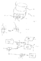
- the in Fig. 1 shown dental furnace 10 has in the illustrated embodiment, a furnace hood 12 and a furnace base 14, on which the furnace hood 12 is pivotally mounted in a conventional manner.
- the furnace base 14 carries at its front in the illustration according to Fig. 1 a display device 16.
- the display device 16 is used according to the invention, wherein in the illustrated operating state in the left area, a substructure 18 of a dental restoration is shown drawn through, and a tooth applied thereto as a dental restoration 20 in dashed form.
- This indication basically shows the dental technician the way in which layers according to the invention he has to build the substructure 18 in order to reach the tooth 22.
- Fig. 2 is shown in a schematic manner, the tooth Z 20, dashed in this case with its outer contour.
- the substructure 18 is again shown by a solid line.
- both representations are present in three-dimensional form, that is, as an envelope in space, the data of the substructure being stored in a storage device 24 in the manner of a database in order to simplify the structure of the layers in detail.
- a first layer whose contours 26 in Fig. 1 are shown schematically, applied to the substructure 18.
- the layer thickness of the layer with the outline 26 is determined in advance in a suitable manner, for example by calculating the spatial difference between the substructure 18 and the outer contour 20 of the tooth. It is understood that it is preferred that each layer has substantially the same layer thickness, if only to be able to realize a uniform through-curing rapidly in the polymerization. For example, if the application of three layers corresponding Fig. 2 is required to achieve the desired layer thickness and thus the outer contour 20, the layer thickness of the first layer 26 is set to about one third of the total layer thickness.
- the actually achieved layer thickness and its three-dimensional outer contour is inventively determined by an image pickup device 30 which is in the form of a three-dimensional camera, or even a camera which is pivotable in all spatial axes and from which a three-dimensional image can be obtained.
- a comparison device 34 is provided, which of course also in electronic form can be realized by software and makes as it were a target / actual comparison.
- the comparison results in a large difference between the target and the actual.
- control device 36 does not specify the processing step to fill this difference, as it were, in one go. Rather, the control device generates on a monitor 38 a target image for the first layer to be generated, which is generated by the control device based on a target / actual comparison and a corresponding subdivision into an integer value, for example 3, or else 8 becomes.
- the desired image displayed on the monitor 38 differs only a little from the actual image of the substructure 18 in the first process step, to which the camera is directed for the comparison between desired and actual.
- the number of layers can be freely selected by the dental technician, with specifications being made by the control device 36 with regard to the selected material and the layer thicknesses to be achieved. For example, if the material to be polymerized is specified for a maximum layer thickness of 1 mm, and a molar must be realized with a total layer thickness of 4 mm, all values from 1 to 3 are disabled for user input, so that only a layer number of 4 to z. B. 10 is adjustable.
- the setting and interaction with the user can be realized via the display device 16, which is then designed as a touch screen, or in a conventional manner via separate control buttons, for example, right and left of the display device 16 in Fig. 1 , or a corresponding indication in the case of using a polymerization.
- the application of the desired layer is preferably via a CAD / CAM system, as is known Fig. 3 can be seen, which is controlled by the control device 36.
- the image acquisition device 30 is directed as above three-dimensional image pickup device on the half product of the dental restoration part, so that the progress of the application is controlled permanently, or at least at regularly recurring times.
- the laying of the next layer, its layer thickness, its color and similar parameters then takes place in the next step in the control device 36.
- This is the target / actual comparison of the comparison device 34 before, and the control device 36 generates a deviation from the target of the originally planned layer construction. For example, if it turns out that the previous layer is too thin at one point - for example, after polymerizing - by 5%, the subsequent layer is made stronger at that point by 5%, so that compensation takes place.
- the layer thickness or the induced errors Apart from the combination of the layer thickness or the induced errors but there is also a compensation of other parameters, sowei this is technically possible. For example, if one layer is realized with too transparent or too little dark material, compared to the originally planned layer structure, the next layer can be realized with a more opaque or darker material without the aesthetic overall appearance being substantially changed. This is especially true for the lower layers.
- the controlled layer production also takes place for the further layers.
- at least two layers are provided, but it is also possible to use a plurality of layers such as ten layers.
- the layers known per se can be realized as layers, or also sub-layers of the layers known per se.
- the layers known per se include the opaquer layer, the dentin layer and the enamel layer (tooth enamel layer), which can each be subdivided individually or as a whole into sublayers.
Abstract
Description
Die Erfindung betrifft ein Verfahren zur Herstellung eines Dentalrestaurationsteils, gemäß dem Oberbegriff von Anspruch 1, sowie einen Dentalofen, gemäß dem Oberbegriff von Anspruch 15.The invention relates to a method for producing a dental restoration part, according to the preamble of claim 1, and to a dental oven, according to the preamble of claim 15.
Es ist seit längerem bekannt, dass die Qualität erzeugter Dentalrestaurationsteile davon abhängt, wie das herzustellende Dentalrestaurationsteil mit den Nachbarzähnen harmoniert. Dies gilt sowohl hinsichtlich der Form als auch der Farbe, aber auch beispielsweise des Farbverlaufs und der Transluszenz.It has long been known that the quality of dental restoration parts produced depends on how the dental restoration part to be produced harmonises with the neighboring teeth. This applies both with regard to the shape and the color, but also, for example, the color gradient and the translucency.
Um ein möglichst naturgetreues und harmonisches Erscheinungsbild des Dentalrestaurationsteils zu erzeugen, ist es bekannt geworden, mittels einer Kamera die Nachbarzähne aufzunehmen und das Erscheinungsbild des Dentalrestaurationsteils in Abhängigkeit hiervon zu erzeugen. Hierbei besteht der Nachteil, dass eine 2D-Kamera nur flächig arbeitet, so dass lediglich die Farbvarianz der Nachbarzähne bei dem Dentalrestaurationsteil abbildbar ist, nicht aber beispielsweise die Transluszenz.In order to produce a lifelike and harmonious appearance of the dental restoration part, it has become known to take the neighboring teeth by means of a camera and to produce the appearance of the dental restoration part in dependence thereon. Here, there is the disadvantage that a 2D camera works only flat, so that only the color variance of the adjacent teeth in the dental restoration part can be imaged, but not, for example, the translucency.
Ferner ist es bekannt geworden, ein Dentalrestaurationsteil mittels CAD/CAM-Verfahren basierend auf den gewonnenen Daten zu erzeugen. Ein Beispiel hierfür lässt sich der
Sämtliche bekannten Verfahren sind bereits seit längerem vorgeschlagen oder veröffentlicht, aber das erreichte Ergebnis hängt stark von der Erfahrung und dem Können des mit der Herstellung des Dentalrestaurationsteils beauftragten Zahntechnikers ab.All known methods have been proposed or published for a long time, but the result obtained depends strongly on the experience and ability of the dental technician responsible for producing the dental restoration part.
Demgegenüber liegt der Erfindung die Aufgabe zugrunde, ein Verfahren zur Herstellung eines Dentalrestaurationsteils gemäß dem Oberbegriff von Anspruch 1 bzw. einen Dentalofen für die Herstellung eines derartigen Dentalrestaurationsteils, gemäß dem Oberbegriff von Anspruch 15 zu schaffen, die eine verbesserte Qualität der erzeugten Dentalrestaurationsteile ermöglichen.In contrast, the invention has for its object to provide a method for producing a dental restoration part according to the preamble of claim 1 and a dental furnace for the production of such a dental restoration part, according to the preamble of claim 15, which allow improved quality of the dental restoration parts produced.
Diese Aufgabe wird erfindungsgemäß durch Anspruch 1 gelöst. Vorteilhafte Weiterbildungen ergeben sich aus den Unteransprüchen.This object is achieved by claim 1. Advantageous developments emerge from the subclaims.
Erfindungsgemäß wird die Herstellung eines Dentalrestaurationsteils gegliedert vorgenommen: Die äußere Kontur des herzustellenden Dentalrestaurationsteils wird durch dreidimensionale Erfassung der Nachbarzähne, beispielsweise über 3D-Kameras, festgelegt. Ferner wird - ebenfalls dreidimensional - der Unterbau festgelegt, und in einer Speichervorrichtung abgespeichert. Hierbei versteht es sich, dass die Speichervorrichtung vorab eine Vielzahl von möglichen Unterbaudaten abspeichern kann, die "passend" zu dem herzustellenden Dentalrestaurationsteil sind, während das dreidimensionale Oberflächenbild des Dentalrestaurationsteils von Fall zu Fall unterschiedlich ist.According to the invention, the production of a dental restoration part is made articulated: The outer contour of the dental restoration part to be produced is determined by three-dimensional detection of the adjacent teeth, for example via 3D cameras. Furthermore, the substructure is also defined in three dimensions, and stored in a memory device. It should be understood that the storage device may previously store a plurality of possible substructure data that is "suitable" for the dental restoration part to be produced, while the three-dimensional surface image of the dental restoration part is different from case to case.
Vorteilhafterweise lässt sich nun basierend auf den dreidimensionalen Oberflächendaten, die der herzustellenden Außenkontur des Dentalrestaurationsteils entsprechen, ein passender Unterbau auswählen.Advantageously, based on the three-dimensional surface data corresponding to the outer contour of the dental restoration part to be produced, a suitable substructure can now be selected.
Nachdem der Unterbau von der Außenkontur überall deutlich beabstandet ist, ist dessen optische Wirkung im Vergleich mit dem Dentalrestaurationsteil im Übrigen am geringsten.After the substructure is clearly spaced from the outer contour everywhere, its optical effect is otherwise the least in comparison with the dental restoration part.
Erfindungsgemäß wird nun der Differenzraum, also das dreidimensionale Gebilde zwischen dem Unterbau und der herzustellenden Außenkontur, in Schichten aufgeteilt, die aufzubringen sind.According to the invention, the differential space, ie the three-dimensional structure between the substructure and the outer contour to be produced, is then divided into layers which are to be applied.
Die Herstellung des Dentalrestaurationsteils wird nun so vorgenommen, dass während der Herstellung das Halbprodukt, also das Dentalrestaurationsteil vor seiner Fertigstellung, visuell erfasst wird, und zwar über eine Bildaufnahmevorrichtung. Die Bildaufnahmevorrichtung kann dann mindestens eine Schicht erfassen, und diese Schicht wird in vorteilhafter Ausgestaltung auch über eine Anzeigevorrichtung angezeigt. Die Erfassung erfolgt hierbei mindestens hinsichtlich der Schichtdicke der Schicht und der Farbe der Schicht über die Bildaufnahmevorrichtung praktisch automatisch.The preparation of the dental restoration part is now carried out so that during production, the half-product, so the dental restoration part before its completion, is visually detected, via an image pickup device. The image recording device can then detect at least one layer, and this layer is displayed in an advantageous embodiment also via a display device. The capture This takes place at least with regard to the layer thickness of the layer and the color of the layer on the image pickup device practically automatically.
Erfindungsgemäß wird nun die erfasste Schicht mindestens hinsichtlich der Schichtdicke mit den Soll-Bilddaten verglichen, und es wird ein Fehlersignal erzeugt, wenn die aufgebrachte Schicht hinsichtlich Schichtdicke und/oder Farbe und/oder anderer Parameter nicht der vorgegebenen Schicht gemäß den Bilddaten entspricht. Die Bilddaten bestehen insofern aus dreidimensionalen Daten zur herzustellenden Außenkontur des Dentalrestaurationsteüs, aber auch aus dreidimensionalen Übergangsdaten, also Daten hinsichtlich der herzustellenden Schicht, basierend auf dem Unterbau bzw. der Differenz zwischen dem Unterbau und der Außenkontur.According to the invention, the detected layer is compared with the desired image data at least with respect to the layer thickness, and an error signal is generated if the layer applied does not correspond to the predetermined layer in terms of layer thickness and / or color and / or other parameters according to the image data. The image data consist insofar of three-dimensional data to be produced outer contour of the Zahnrestaurationsteüs, but also from three-dimensional transition data, ie data regarding the layer to be produced, based on the substructure or the difference between the substructure and the outer contour.
Das Fehlersignal wird dann erzeugt, wenn die Abweichung zwischen dem vorgegebenen Schichtdaten gemäß den Bilddaten und der von der Bildaufnahmevorrichtung erfassten Werte einen Schwellwert übersteigt. Wenn die Abweichung geringer als der Schwellwert ist, wird kurzerhand die Schichtdicke oder ein sonstiger Parameter der nachfolgenden Schicht entsprechend angepasst.The error signal is generated when the deviation between the predetermined layer data according to the image data and the values detected by the image pickup device exceeds a threshold value. If the deviation is less than the threshold value, the layer thickness or another parameter of the subsequent layer is adapted without further ado.
Beispielhaft wird dies so vorgenommen, dass, wenn die Schichtdicke, die auf dem Unterbau aufgetragen ist, an einer Stelle 5 % größer als vorgegeben ist, die nachfolgende Schicht in ihrer Schichtdicke entsprechend angepasst wird, also um das den 5 % entsprechende Maß an dieser Stelle dünner hergestellt wird.By way of example, this is done so that, if the layer thickness, which is applied to the substructure at one point 5% greater than predetermined, the subsequent layer is adjusted accordingly in their layer thickness, ie the corresponding 5% measure at this point is made thinner.
Überraschend lassen sich mit der erfindungsgemäßen Schichtdickenregelung oder Schichtparameterregelung der Aufbau eines Dentalrestaurationsteils wesentlich verbessern und insbesondere unabhängiger von dem Geschick und der Erfahrung des beauftragten Zahntechnikers machen. Der Zahntechniker bekommt automatisch bei der Erstellung des Dentalrestaurationsteils Hinweise, beispielsweise auf einer Anzeigevorrichtung, dass bestimmte Parameter an bestimmten Stellen nicht ganz korrekt sind, und es werden automatisch Hinweise eingeblendet, wie die entsprechenden Abweichungen bei der nächsten aufzubringenden Schicht zu korrigieren sind.Surprisingly, with the layer thickness control or layer parameter regulation according to the invention, the construction of a dental restoration part can be substantially improved and, in particular, made more independent of the skill and experience of the assigned dental technician. The dental technician automatically gets hints when creating the dental restoration part, for example on a display device, that certain parameters are not completely correct at certain points, and automatically hints are displayed as to how to correct the corresponding deviations in the next layer to be applied.
Dies gilt gleichermaßen für Farbfehler, die ebenfalls bei den unteren Schichten in gewissem Maße ausgeglichen bzw. kompensiert werden können, indem hinsichtlich der Farbe dann bei der nächstfolgenden Schicht gegengesteuert wird.This also applies to color errors, which can also be compensated for to some extent in the lower layers, by then being counteracted with respect to the color in the next following layer.
In vorteilhafter Ausgestaltung ist eine Nachführeinrichtung vorgesehen, die die Bildaufnahmevorrichtung bei der Aufnahme des Dentalrestaurationsteils während seiner Entstehung nachführt, so dass stets die dreidimensional erfasste Oberfläche der betreffenden Schicht im Fokus der Bildaufnahmevorrichtung liegt.In an advantageous embodiment, a tracking device is provided, which is the image recording device when receiving the dental restoration part during its formation so that the three-dimensionally detected surface of the relevant layer is always in the focus of the image recording device.
Die Anzeige auf der Anzeigevorrichtung zur Darstellung der aufgebrachten Schicht kann in beliebiger Art und Weise erfolgen, bevorzugt sowohl in Form von Linien oder Hüllkurven als auch über numerische Werte.The display on the display device for displaying the applied layer can be done in any manner, preferably in the form of lines or envelopes as well as numerical values.
In weiterer vorteilhafter Ausgestaltung ist eine Datenbrille oder ein head mounted display als Anzeigevorrichtung vorgesehen, die dann gleich die Korrekturen für die nächsten aufzubringenden Schichten oder die nächste aufzubringende Schicht im Sinne einer gemischten Realität in das von der dreidimensionalen Kamera aufgenommene Bild einblendet.In a further advantageous embodiment, a data glasses or a head mounted display is provided as a display device, which then immediately displays the corrections for the next applied layers or the next layer to be applied in the sense of a mixed reality in the captured by the three-dimensional camera image.
Das erfindungsgemäße Verfahren lässt sich sowohl bei keramischen oder Komposit-Dentalrestaurationsteilen, aber auch bei zu polymerisierenden Dentalrestaurationsteilen einsetzen, und es ist günstig, dass das erfindungsgemäße Verfahren iterativ realisierbar ist, so dass mit der gleichen Ausrüstung von Schicht zu Schicht die gleichen Schritte bis zur letzten Schicht realisierbar sind.The method according to the invention can be used both in ceramic or composite dental restoration parts, but also in dental restoration parts to be polymerized, and it is favorable that the method according to the invention can be carried out iteratively, so that the same steps from one layer to the next can be carried out with the same equipment Layer are feasible.
Sowohl im Dentalofen als auch beim Polymerisieren erfolgt typischerweise eine Schrumpfung des aufgebrachten Dentalrestaurationsmaterials. Dies lässt sich bevorzugt je kompensieren, und zwar entweder, indem die aktuelle Schicht in einem gewissen Übermaß aufgetragen wird, oder indem für die nächste Schicht ein Übermaß einkalkuliert wird, um die Schrumpfung zu kompensieren.Both in the dental oven and during polymerization typically occurs a shrinkage of the applied dental restoration material. This can preferably be compensated for, either by applying the current layer to a certain degree of excess, or by taking an excess for the next layer in order to compensate for the shrinkage.
Es versteht sich, dass das Aufbringen der Schichten gerade beim Einsatz von zu polymerisierenden Materialien auch je abwechselnd mit Polymerisationsschritten erfolgen kann, so dass das Schrumpfungsergebnis durch die erfindungsgemäße Bildaufnahmevorrichtung kompensierbar ist.It is self-evident that the application of the layers, even when using materials to be polymerized, can also take place alternately with polymerization steps, so that the shrinkage result can be compensated by the image recording device according to the invention.
Bei Realisierung des Dentalrestaurationsteils als in einem Dentalofen zu brennendes Dentalrestaurationsteil lässt sich auch eine Programmsteuerung des Ofens basierend auf dem Vergleichsergebnis des Vergleichs zwischen dem aufgenommenen Bild des herzustellenden Dentalrestaurationsteils und den Bilddaten vornehmen, die vorab in dem Dentalofen oder getrennt von diesem abgespeichert sind, insbesondere in einer Speichervorrichtung, die eine Datenbank aufweist, und es lässt sich auch eine Sicherheitsfunktion einbauen, die ein Einschalten des Ofens verhindert, wenn die Divergenz zwischen dem aufgenommenen Bild der Bildaufnahmevorrichtung und dem abgespeicherten Bild ein vorgegebenes Maß übersteigt.When realizing the dental restoration part as a dental restoration part to be burned in a dental furnace, program control of the furnace based on the comparison result of the comparison between the captured image of the dental restoration part to be manufactured and the image data stored in advance in the dental furnace or separately therefrom, in particular in FIG a memory device having a database, and it is also possible to incorporate a safety function that prevents the oven from turning on when the divergence between the captured image of the image capture device and the stored image exceeds a predetermined amount.
Hierbei lässt sich die Abweichung entweder automatisch durch Bildauswertung erfassen, oder hilfsweise auch durch visuelle Beurteilung.Here, the deviation can be detected either automatically by image analysis, or alternatively by visual assessment.
Es ist auch möglich, die beiden Bilder elektronisch übereinander zu legen und über eine Differenzeinfärbung die Unterschiede deutlich zu machen, um dem Benutzer Hinweise hinsichtlich der Abweichungen zu geben und eine entsprechende Beurteilung hinsichtlich der weiteren, zu erbringenden Schritte zu erlauben.It is also possible to superimpose the two images electronically and to make the differences clear by means of a differential staining in order to give the user information about the deviations and to allow a corresponding assessment with regard to the further steps to be performed.
Weitere Vorteile, Einzelheiten und Merkmale ergeben sich aus der nachfolgenden Beschreibung eines Ausführungsbeispiels der Erfindung anhand der Zeichnung.Further advantages, details and features will become apparent from the following description of an embodiment of the invention with reference to the drawing.
Es zeigen:
- Fig. 1
- eine schematische Ansicht eines erfindungsgemäßen Dentalofens, zur beispielhaften Ausführung eines erfindungsgemäßen Verfahrens;
- Fig. 2
- eine schematische Darstellung einer erfindungsgemäßen Bildaufnahmevorrichtung mit dem partiell hergestellten Dentalrestaurationsteil; und
- Fig. 3
- eine schematisch dargestellte Funktion des erfindungsgemäßen Verfahrens.
- Fig. 1
- a schematic view of a dental oven according to the invention, for exemplary embodiment of a method according to the invention;
- Fig. 2
- a schematic representation of an image pickup device according to the invention with the partially prepared dental restoration part; and
- Fig. 3
- a schematically illustrated function of the method according to the invention.
Der in
Das Ofenunterteil 14 trägt an seiner Vorderseite in der Darstellung gemäß
Demgegenüber ist in dem rechten Bereich der Anzeigevorrichtung 16 ein Zahn 22 dargestellt, dessen Bild aus einer Bildaufnahmevorrichtung gewonnen ist, wobei die Nachbarzähne des herzustellenden Zahns 20 dargestellt sind.On the other hand, in the right-hand area of the
Diese Anzeige weist dem Zahntechniker dem Grunde nach den Weg, in welchen erfindungsgemäßen Schichten er den Unterbau 18 aufbauen muss, um zu dem Zahn 22 zu gelangen.This indication basically shows the dental technician the way in which layers according to the invention he has to build the
Während hier das erfindungsgemäße Verfahren anhand eines Dentalofens dargestellt ist, versteht es sich, dass in gleicher Weise die Erfindung auch die Herstellung eines Dentalrestaurationsteils mittels eines Polymerisationsgeräts erlaubt.While here the method according to the invention is illustrated with reference to a dental oven, it is understood that in the same way the invention also permits the production of a dental restoration part by means of a polymerization device.
In
Dies kann in beliebiger geeigneter Weise erfolgen, beispielsweise auch über eines der bekannten Rapid-Prototyping-Verfahren, wobei die Schichtdicke sich dann aus der Anzahl und Anordnung der aufgebrachten Voxel ergibt.This can be done in any suitable manner, for example via one of the known rapid prototyping methods, the layer thickness then resulting from the number and arrangement of the applied voxels.
Die Schichtdicke der Schicht mit dem Umriss 26 wird in geeigneter Weise vorab festgelegt, beispielsweise durch Berechnung der räumlichen Differenz zwischen dem Unterbau 18 und der Außenkontur 20 des Zahns. Es versteht sich, dass es bevorzugt ist, dass jede Schicht im Wesentlichen die gleiche Schichtstärke aufweist, allein schon, um bei der Polymerisation eine gleichmäßige Durchhärtung rasch realisieren zu können. Wenn beispielsweise die Aufbringung von drei Schichten entsprechend
Die tatsächlich erzielte Schichtstärke und deren dreidimensionale Außenkontur wird erfindungsgemäß durch eine Bildaufnahmevorrichtung 30 ermittelt, die in Form einer dreidimensionalen Kamera ausgebildet ist, oder aber auch einer Kamera, die in alle Raumachsen verschwenkbar ist und aus der ein dreidimensionales Bild gewinnbar ist.The actually achieved layer thickness and its three-dimensional outer contour is inventively determined by an
Aus
Die entsprechenden Bilddaten werden elektronisch ausgewertet und aufbereitet, so dass ein dreidimensionaler Vergleich möglich ist. Hierzu ist gemäß
Im ersten Schritt ergibt sich aus dem Vergleich ein großer Unterscheid zwischen Soll- und Ist.In the first step, the comparison results in a large difference between the target and the actual.
Mit der Steuervorrichtung 36 wird jedoch nicht der Bearbeitungsschritt vorgegeben, diesen Unterschied gleichsam in einem Zuge auszufüllen. Vielmehr erzeugt die Steuervorrichtung auf einem Monitor 38 ein Soll-Bild für die erste zu erzeugende Schicht, die von der Steuervorrichtung basierend auf einem Soll-/Ist-Vergleich und einer entsprechenden Unterteilung in einen ganzzahligen Wert, beispielsweise 3, oder aber auch 8, erzeugt wird.However, the
Dementsprechend unterscheidet sich bei einer gewählten Schichtanzahl von 8 das auf dem Monitor 38 dargestellte Soll-Bild nur um weniges von dem Ist-Bild des Unterbaus 18 in dem ersten Verfahrensschritt, auf welchen die Kamera für den Abgleich zwischen Soll- und Ist gerichtet wird.Accordingly, with a selected number of layers of 8, the desired image displayed on the
Die Anzahl der Schichten lässt sich vom Zahntechniker frei wählen, wobei hinsichtlich des gewählten Materials und der demit zu erreichenden Schichtstärken Vorgaben von der Steuervorrichtung 36 gemacht werden. Wenn das zu polymerisierende Material beispielsweise für eine maximale Schichtstärke von 1 mm spezifiziert ist, und ein Molar muss mit einer Gesamtschichtstärke von 4mm realisiert werden, werden für die Eingabe durch den Benutzer alle Werte von 1 bis 3 gesperrt, so dass lediglich eine Schichtenanzahl von 4 bis z. B. 10 einstellbar ist.The number of layers can be freely selected by the dental technician, with specifications being made by the
Die Einstellung und Interaktion mit dem Benutzer kann hierbei über die Anzeigevorrichtung 16 realisiert sein, die dann als Touchscreen ausgebildet ist, oder aber in an sich bekannter Weise über separate Bedientasten, beispielsweise rechts und links der Anzeigevorrichtung 16 in
Nachdem die Schichtdicke, aber auch die Materialwahl, der Farbton und die Farbvarianz, aber auch weitere chromatische Parameter, einschließlich der Transparenz, vorgegeben sind, erfolgt die Aufbringung der erwünschten Schicht bevorzugt über ein CAD/CAM-System, wie es aus
Es versteht sich, dass es anstelle dessen auch möglich ist, die Schicht nach der Vorgabe der Steuervorrichtung manuell aufzubringen.It is understood that instead of this it is also possible to apply the layer manually according to the specification of the control device.
Während des Aufbringens, aber spätestens beim Beenden der Aufbringung der betreffenden Schicht, ist die Bildaufnahmevorrichtung 30 wie vorstehend dargelegt als dreidimensionale Bildaufnahmevorrichtung auf das Halbprodukt des Dentalrestaurationsteils gerichtet, so dass permanent, oder zumindest in regelmäßig wiederkehrenden Zeitpunkten, der Fortschritt der Aufbringung kontrolliert wird.During the application, but no later than the completion of the application of the respective layer, the
In diesem nächsten Schritt wird dann in einem Soll-Ist-Vergleich ein Vergleich mit der aus der Steuervorrichtung 36 abgezweigten Vorgabe gemacht, wozu die Verbindungslinie 40 in
Die Legung der nächsten Schicht, deren Schichtstärke, deren Farbe und ähnlicher Parameter erfolgt dann im nächsten Schritt wiederum in der Steuervorrichtung 36. Dieser liegt der Soll-/Ist-Vergleich der Vergleichsvorrichtung 34 vor, und die Steuervorrichtung 36 erzeugt hieraus eine Abweichung vom Soll des ursprünglich geplanten Schichtaufbaus. Wenn sich beispielsweise herausstellt, dass die vorige Schicht an einer Stelle - beispielsweise nach dem Polymerisieren - um 5 % zu dünn ist, wird die nachfolgende Schicht an dieser Stelle um 5 % stärker gemacht, so dass insofern eine Kompensation erfolgt.The laying of the next layer, its layer thickness, its color and similar parameters then takes place in the next step in the
Abgesehen von der Kombination der Schichtstärke bzw. der dort induzierten Fehler erfolgt aber auch eine Kompensation weiterer Parameter, sowei dies technisch möglich ist. Wenn beispielsweise eine Schicht mit einem zu transparenten oder zu wenig dunklem Material realisiert ist, gegenüber dem ursprünglich geplanten Schichtaufbau, kann die nächste Schicht mit einem opakeren bzw. dunklerem Material realisiert werden, ohne dass das ästhetische Gesamterscheinungsbild wesentlich verändert ist. Dies gilt in besonderem Maße für die unteren Schichten.Apart from the combination of the layer thickness or the induced errors but there is also a compensation of other parameters, sowei this is technically possible. For example, if one layer is realized with too transparent or too little dark material, compared to the originally planned layer structure, the next layer can be realized with a more opaque or darker material without the aesthetic overall appearance being substantially changed. This is especially true for the lower layers.
In gleicher Weise wie hier bei der ersten und zweiten Schicht beschrieben, erfolgt die geregelte Schichterzeugung auch für die weiteren Schichten. Erfindungsgemäß sin mindestens zwei Schichten vorgesehen, es ist jedoch auch möglich, eine Vielzahl von Schichten wie beispielsweise zehn Schichten einzusetzen.In the same way as described here in the first and second layer, the controlled layer production also takes place for the further layers. According to the invention at least two layers are provided, but it is also possible to use a plurality of layers such as ten layers.
Während hier Kamera und Monitor, aber auch die Anzeigevorrichtung 16 gemäß
Es versteht sich, dass als Schichten die an sich bekannten Schichten realisiert werden können, oder aber auch Sub-Schichten der an sich bekannten Schichten. Zu den an sich bekannten Schichten gehört die Opakerschicht, die Dentinschicht und die Enamelschicht (Zahnschmelzschicht), die je einzeln oder insgesamt in Subschichten unterteilbar sind.It is understood that the layers known per se can be realized as layers, or also sub-layers of the layers known per se. The layers known per se include the opaquer layer, the dentin layer and the enamel layer (tooth enamel layer), which can each be subdivided individually or as a whole into sublayers.
Claims (16)
dass die erfasste Schicht mindestens hinsichtlich der Schichtdicke mit den Bilddaten (32) verglichen wird,
dass ein Fehlersignal erzeugt wird, wenn die aufgebrachte Schicht hinsichtlich ihrer Schichtdicke und/oder Farbe und/oder der anderen Parameter nicht der vorgegebenen Schicht gemäß den Bilddaten (32) entspricht.Method for producing a dental restoration part, and dental oven, in which the dental restoration part is produced on a substructure by applying at least two layers, output data, in particular three-dimensional data of the substructure, being stored in a storage device, and image data, in particular three-dimensional data for the outer contour of the to be produced Dental restoration parts and the applied layers of the dental restoration part, fixed and in particular stored, characterized in that the dental restoration part at least partially during its production in the image pick-up area of an image pickup device (30), and that before the completion of the dental restoration part (20) and after applying at least one layer this is detected at least with regard to its layer thickness and / or color, in particular via a display device (16) is displayed,
that the detected layer is compared with the image data (32) at least with respect to the layer thickness,
an error signal is generated if the layer applied does not correspond to the predetermined layer in terms of its layer thickness and / or color and / or the other parameters in accordance with the image data (32).
Priority Applications (5)
| Application Number | Priority Date | Filing Date | Title |
|---|---|---|---|
| ES12197844.9T ES2669545T3 (en) | 2012-12-18 | 2012-12-18 | Procedure for making a dental restoration piece, as well as a dental oven |
| EP12197844.9A EP2745801B1 (en) | 2012-12-18 | 2012-12-18 | Method for producing a dental restoration part, and dental oven |
| PCT/EP2013/072287 WO2014095134A1 (en) | 2012-12-18 | 2013-10-24 | Method for producing a dental restoration part, and dental furnace |
| CN201380066046.7A CN104883996B (en) | 2012-12-18 | 2013-10-24 | Manufacture the method and dental stove of Dental Erosion part |
| US14/367,962 US9579171B2 (en) | 2012-12-18 | 2013-10-24 | Process for manufacturing a dental restoration part and a dental furnace for manufacturing the same |
Applications Claiming Priority (1)
| Application Number | Priority Date | Filing Date | Title |
|---|---|---|---|
| EP12197844.9A EP2745801B1 (en) | 2012-12-18 | 2012-12-18 | Method for producing a dental restoration part, and dental oven |
Publications (2)
| Publication Number | Publication Date |
|---|---|
| EP2745801A1 true EP2745801A1 (en) | 2014-06-25 |
| EP2745801B1 EP2745801B1 (en) | 2018-02-21 |
Family
ID=47552779
Family Applications (1)
| Application Number | Title | Priority Date | Filing Date |
|---|---|---|---|
| EP12197844.9A Not-in-force EP2745801B1 (en) | 2012-12-18 | 2012-12-18 | Method for producing a dental restoration part, and dental oven |
Country Status (5)
| Country | Link |
|---|---|
| US (1) | US9579171B2 (en) |
| EP (1) | EP2745801B1 (en) |
| CN (1) | CN104883996B (en) |
| ES (1) | ES2669545T3 (en) |
| WO (1) | WO2014095134A1 (en) |
Cited By (1)
| Publication number | Priority date | Publication date | Assignee | Title |
|---|---|---|---|---|
| CN106361455A (en) * | 2016-10-13 | 2017-02-01 | 成都优材科技有限公司 | 3D printing forming method for metal dental restoration |
Families Citing this family (7)
| Publication number | Priority date | Publication date | Assignee | Title |
|---|---|---|---|---|
| US10771697B2 (en) * | 2016-09-06 | 2020-09-08 | Apple Inc. | Still image stabilization/optical image stabilization synchronization in multi-camera image capture |
| US10660728B2 (en) * | 2016-10-20 | 2020-05-26 | Baliram Maraj | Systems and methods for dental treatment utilizing mixed reality and deep learning |
| CN110870797A (en) * | 2018-08-31 | 2020-03-10 | 柳州市佛冠齿科数字化研发有限公司 | Porcelain tooth comparison device |
| US10315353B1 (en) | 2018-11-13 | 2019-06-11 | SmileDirectClub LLC | Systems and methods for thermoforming dental aligners |
| US11007042B2 (en) | 2019-02-06 | 2021-05-18 | Sdc U.S. Smilepay Spv | Systems and methods for marking models for dental aligner fabrication |
| US10482192B1 (en) | 2019-02-12 | 2019-11-19 | SmileDirectClub LLC | Systems and methods for selecting and marking a location on a dental aligner |
| TWI710357B (en) * | 2020-01-17 | 2020-11-21 | 東昕精密科技股份有限公司 | AR dental prosthesis manufacturing guidance system and its application method |
Citations (6)
| Publication number | Priority date | Publication date | Assignee | Title |
|---|---|---|---|---|
| WO2000008415A1 (en) * | 1998-08-05 | 2000-02-17 | Cadent Ltd. | Imaging a three-dimensional structure by confocal focussing an array of light beams |
| DE10113753A1 (en) | 2001-03-21 | 2002-09-26 | Dentsply Detrey Gmbh | Process data transmission method uses stationary transmitter and cooperating mobile receivers for transmission of data over large distance |
| EP1561433A1 (en) * | 2004-02-09 | 2005-08-10 | Cadent Limited | Method and system for manufacturing a dental prosthesis |
| DE102004002724B4 (en) | 2004-01-19 | 2006-06-14 | Ivoclar Vivadent Ag | Kiln and method for operating a kiln for the dental field |
| EP2550928A1 (en) * | 2011-07-25 | 2013-01-30 | Ivoclar Vivadent AG | Dental oven with a drying sensor |
| EP2551621A1 (en) * | 2011-07-25 | 2013-01-30 | Ivoclar Vivadent AG | Muffle switch |
Family Cites Families (2)
| Publication number | Priority date | Publication date | Assignee | Title |
|---|---|---|---|---|
| US5121334A (en) * | 1989-06-08 | 1992-06-09 | Regents Of The University Of Minnesota | Method and apparatus for automated machining of objects of complex and unique geometry |
| DE102007053071A1 (en) * | 2007-11-07 | 2009-05-14 | Ivoclar Vivadent Ag | kiln |
-
2012
- 2012-12-18 EP EP12197844.9A patent/EP2745801B1/en not_active Not-in-force
- 2012-12-18 ES ES12197844.9T patent/ES2669545T3/en active Active
-
2013
- 2013-10-24 WO PCT/EP2013/072287 patent/WO2014095134A1/en active Application Filing
- 2013-10-24 CN CN201380066046.7A patent/CN104883996B/en not_active Expired - Fee Related
- 2013-10-24 US US14/367,962 patent/US9579171B2/en active Active
Patent Citations (6)
| Publication number | Priority date | Publication date | Assignee | Title |
|---|---|---|---|---|
| WO2000008415A1 (en) * | 1998-08-05 | 2000-02-17 | Cadent Ltd. | Imaging a three-dimensional structure by confocal focussing an array of light beams |
| DE10113753A1 (en) | 2001-03-21 | 2002-09-26 | Dentsply Detrey Gmbh | Process data transmission method uses stationary transmitter and cooperating mobile receivers for transmission of data over large distance |
| DE102004002724B4 (en) | 2004-01-19 | 2006-06-14 | Ivoclar Vivadent Ag | Kiln and method for operating a kiln for the dental field |
| EP1561433A1 (en) * | 2004-02-09 | 2005-08-10 | Cadent Limited | Method and system for manufacturing a dental prosthesis |
| EP2550928A1 (en) * | 2011-07-25 | 2013-01-30 | Ivoclar Vivadent AG | Dental oven with a drying sensor |
| EP2551621A1 (en) * | 2011-07-25 | 2013-01-30 | Ivoclar Vivadent AG | Muffle switch |
Cited By (1)
| Publication number | Priority date | Publication date | Assignee | Title |
|---|---|---|---|---|
| CN106361455A (en) * | 2016-10-13 | 2017-02-01 | 成都优材科技有限公司 | 3D printing forming method for metal dental restoration |
Also Published As
| Publication number | Publication date |
|---|---|
| US9579171B2 (en) | 2017-02-28 |
| ES2669545T3 (en) | 2018-05-28 |
| US20150238288A1 (en) | 2015-08-27 |
| CN104883996B (en) | 2017-08-08 |
| WO2014095134A1 (en) | 2014-06-26 |
| EP2745801B1 (en) | 2018-02-21 |
| CN104883996A (en) | 2015-09-02 |
Similar Documents
| Publication | Publication Date | Title |
|---|---|---|
| EP2745801B1 (en) | Method for producing a dental restoration part, and dental oven | |
| EP2486892B1 (en) | Method for manufacturing a dental restoration part and CAD/CAM device | |
| EP1782752B1 (en) | Method and device for producing dentures | |
| EP1614396A1 (en) | Method of producing dental prostheses | |
| EP1903979B1 (en) | Method and device for producing dental prosthesis elements | |
| EP2672461A1 (en) | Method for continuing recordings to detect three-dimensional geometries of objects | |
| EP0913130A2 (en) | Method and device for manufacturing a dental prosthesis | |
| EP1555499B1 (en) | Kiln as well as method for operating a kiln for dentistry | |
| WO2018162671A1 (en) | Method for defining the colour of a material of a dental restoration | |
| EP1155663A2 (en) | Colour definition device as well as a method for determining and defining the colours for teeth and dental restorations | |
| EP3111882B1 (en) | Method for producing an individually manufactured dental replacement structure | |
| EP3984493B1 (en) | Method for producing a dental restoration | |
| DE102007002143A1 (en) | Method for modeling or producing a denture restoration, computer readable medium and computer | |
| EP3636218A1 (en) | Method for producing a dental prosthetic | |
| EP1865880B1 (en) | Method for producing metallic dental restoration elements | |
| EP2965710A1 (en) | Individualised negative forms | |
| WO2009026943A1 (en) | Production of a dental prosthesis | |
| EP3043741B1 (en) | Method for producing a dental prosthesis | |
| AT512985B1 (en) | Process for producing a dental prosthesis | |
| DE102016213243A1 (en) | Method for planning and manufacturing a tooth replacement part |
Legal Events
| Date | Code | Title | Description |
|---|---|---|---|
| PUAI | Public reference made under article 153(3) epc to a published international application that has entered the european phase |
Free format text: ORIGINAL CODE: 0009012 |
|
| 17P | Request for examination filed |
Effective date: 20121218 |
|
| AK | Designated contracting states |
Kind code of ref document: A1 Designated state(s): AL AT BE BG CH CY CZ DE DK EE ES FI FR GB GR HR HU IE IS IT LI LT LU LV MC MK MT NL NO PL PT RO RS SE SI SK SM TR |
|
| AX | Request for extension of the european patent |
Extension state: BA ME |
|
| R17P | Request for examination filed (corrected) |
Effective date: 20140625 |
|
| RBV | Designated contracting states (corrected) |
Designated state(s): AL AT BE BG CH CY CZ DE DK EE ES FI FR GB GR HR HU IE IS IT LI LT LU LV MC MK MT NL NO PL PT RO RS SE SI SK SM TR |
|
| 17Q | First examination report despatched |
Effective date: 20160215 |
|
| GRAP | Despatch of communication of intention to grant a patent |
Free format text: ORIGINAL CODE: EPIDOSNIGR1 |
|
| INTG | Intention to grant announced |
Effective date: 20170922 |
|
| GRAS | Grant fee paid |
Free format text: ORIGINAL CODE: EPIDOSNIGR3 |
|
| GRAA | (expected) grant |
Free format text: ORIGINAL CODE: 0009210 |
|
| AK | Designated contracting states |
Kind code of ref document: B1 Designated state(s): AL AT BE BG CH CY CZ DE DK EE ES FI FR GB GR HR HU IE IS IT LI LT LU LV MC MK MT NL NO PL PT RO RS SE SI SK SM TR |
|
| REG | Reference to a national code |
Ref country code: GB Ref legal event code: FG4D Free format text: NOT ENGLISH |
|
| REG | Reference to a national code |
Ref country code: CH Ref legal event code: EP |
|
| REG | Reference to a national code |
Ref country code: AT Ref legal event code: REF Ref document number: 970868 Country of ref document: AT Kind code of ref document: T Effective date: 20180315 |
|
| REG | Reference to a national code |
Ref country code: IE Ref legal event code: FG4D Free format text: LANGUAGE OF EP DOCUMENT: GERMAN |
|
| REG | Reference to a national code |
Ref country code: DE Ref legal event code: R096 Ref document number: 502012012182 Country of ref document: DE |
|
| REG | Reference to a national code |
Ref country code: CH Ref legal event code: NV Representative=s name: KELLER AND PARTNER PATENTANWAELTE AG, CH |
|
| REG | Reference to a national code |
Ref country code: ES Ref legal event code: FG2A Ref document number: 2669545 Country of ref document: ES Kind code of ref document: T3 Effective date: 20180528 |
|
| REG | Reference to a national code |
Ref country code: SE Ref legal event code: TRGR |
|
| REG | Reference to a national code |
Ref country code: NL Ref legal event code: MP Effective date: 20180221 |
|
| REG | Reference to a national code |
Ref country code: LT Ref legal event code: MG4D |
|
| PG25 | Lapsed in a contracting state [announced via postgrant information from national office to epo] |
Ref country code: NO Free format text: LAPSE BECAUSE OF FAILURE TO SUBMIT A TRANSLATION OF THE DESCRIPTION OR TO PAY THE FEE WITHIN THE PRESCRIBED TIME-LIMIT Effective date: 20180521 Ref country code: CY Free format text: LAPSE BECAUSE OF FAILURE TO SUBMIT A TRANSLATION OF THE DESCRIPTION OR TO PAY THE FEE WITHIN THE PRESCRIBED TIME-LIMIT Effective date: 20180221 Ref country code: FI Free format text: LAPSE BECAUSE OF FAILURE TO SUBMIT A TRANSLATION OF THE DESCRIPTION OR TO PAY THE FEE WITHIN THE PRESCRIBED TIME-LIMIT Effective date: 20180221 Ref country code: NL Free format text: LAPSE BECAUSE OF FAILURE TO SUBMIT A TRANSLATION OF THE DESCRIPTION OR TO PAY THE FEE WITHIN THE PRESCRIBED TIME-LIMIT Effective date: 20180221 Ref country code: LT Free format text: LAPSE BECAUSE OF FAILURE TO SUBMIT A TRANSLATION OF THE DESCRIPTION OR TO PAY THE FEE WITHIN THE PRESCRIBED TIME-LIMIT Effective date: 20180221 Ref country code: HR Free format text: LAPSE BECAUSE OF FAILURE TO SUBMIT A TRANSLATION OF THE DESCRIPTION OR TO PAY THE FEE WITHIN THE PRESCRIBED TIME-LIMIT Effective date: 20180221 |
|
| PG25 | Lapsed in a contracting state [announced via postgrant information from national office to epo] |
Ref country code: BG Free format text: LAPSE BECAUSE OF FAILURE TO SUBMIT A TRANSLATION OF THE DESCRIPTION OR TO PAY THE FEE WITHIN THE PRESCRIBED TIME-LIMIT Effective date: 20180521 Ref country code: GR Free format text: LAPSE BECAUSE OF FAILURE TO SUBMIT A TRANSLATION OF THE DESCRIPTION OR TO PAY THE FEE WITHIN THE PRESCRIBED TIME-LIMIT Effective date: 20180522 Ref country code: RS Free format text: LAPSE BECAUSE OF FAILURE TO SUBMIT A TRANSLATION OF THE DESCRIPTION OR TO PAY THE FEE WITHIN THE PRESCRIBED TIME-LIMIT Effective date: 20180221 Ref country code: LV Free format text: LAPSE BECAUSE OF FAILURE TO SUBMIT A TRANSLATION OF THE DESCRIPTION OR TO PAY THE FEE WITHIN THE PRESCRIBED TIME-LIMIT Effective date: 20180221 |
|
| PG25 | Lapsed in a contracting state [announced via postgrant information from national office to epo] |
Ref country code: MT Free format text: LAPSE BECAUSE OF FAILURE TO SUBMIT A TRANSLATION OF THE DESCRIPTION OR TO PAY THE FEE WITHIN THE PRESCRIBED TIME-LIMIT Effective date: 20180221 |
|
| PG25 | Lapsed in a contracting state [announced via postgrant information from national office to epo] |
Ref country code: PL Free format text: LAPSE BECAUSE OF FAILURE TO SUBMIT A TRANSLATION OF THE DESCRIPTION OR TO PAY THE FEE WITHIN THE PRESCRIBED TIME-LIMIT Effective date: 20180221 Ref country code: EE Free format text: LAPSE BECAUSE OF FAILURE TO SUBMIT A TRANSLATION OF THE DESCRIPTION OR TO PAY THE FEE WITHIN THE PRESCRIBED TIME-LIMIT Effective date: 20180221 Ref country code: RO Free format text: LAPSE BECAUSE OF FAILURE TO SUBMIT A TRANSLATION OF THE DESCRIPTION OR TO PAY THE FEE WITHIN THE PRESCRIBED TIME-LIMIT Effective date: 20180221 Ref country code: AL Free format text: LAPSE BECAUSE OF FAILURE TO SUBMIT A TRANSLATION OF THE DESCRIPTION OR TO PAY THE FEE WITHIN THE PRESCRIBED TIME-LIMIT Effective date: 20180221 |
|
| REG | Reference to a national code |
Ref country code: FR Ref legal event code: PLFP Year of fee payment: 7 |
|
| REG | Reference to a national code |
Ref country code: DE Ref legal event code: R097 Ref document number: 502012012182 Country of ref document: DE |
|
| PG25 | Lapsed in a contracting state [announced via postgrant information from national office to epo] |
Ref country code: DK Free format text: LAPSE BECAUSE OF FAILURE TO SUBMIT A TRANSLATION OF THE DESCRIPTION OR TO PAY THE FEE WITHIN THE PRESCRIBED TIME-LIMIT Effective date: 20180221 Ref country code: SK Free format text: LAPSE BECAUSE OF FAILURE TO SUBMIT A TRANSLATION OF THE DESCRIPTION OR TO PAY THE FEE WITHIN THE PRESCRIBED TIME-LIMIT Effective date: 20180221 Ref country code: SM Free format text: LAPSE BECAUSE OF FAILURE TO SUBMIT A TRANSLATION OF THE DESCRIPTION OR TO PAY THE FEE WITHIN THE PRESCRIBED TIME-LIMIT Effective date: 20180221 Ref country code: CZ Free format text: LAPSE BECAUSE OF FAILURE TO SUBMIT A TRANSLATION OF THE DESCRIPTION OR TO PAY THE FEE WITHIN THE PRESCRIBED TIME-LIMIT Effective date: 20180221 |
|
| PLBE | No opposition filed within time limit |
Free format text: ORIGINAL CODE: 0009261 |
|
| STAA | Information on the status of an ep patent application or granted ep patent |
Free format text: STATUS: NO OPPOSITION FILED WITHIN TIME LIMIT |
|
| 26N | No opposition filed |
Effective date: 20181122 |
|
| PG25 | Lapsed in a contracting state [announced via postgrant information from national office to epo] |
Ref country code: SI Free format text: LAPSE BECAUSE OF FAILURE TO SUBMIT A TRANSLATION OF THE DESCRIPTION OR TO PAY THE FEE WITHIN THE PRESCRIBED TIME-LIMIT Effective date: 20180221 |
|
| PG25 | Lapsed in a contracting state [announced via postgrant information from national office to epo] |
Ref country code: LU Free format text: LAPSE BECAUSE OF NON-PAYMENT OF DUE FEES Effective date: 20181218 Ref country code: MC Free format text: LAPSE BECAUSE OF FAILURE TO SUBMIT A TRANSLATION OF THE DESCRIPTION OR TO PAY THE FEE WITHIN THE PRESCRIBED TIME-LIMIT Effective date: 20180221 |
|
| REG | Reference to a national code |
Ref country code: IE Ref legal event code: MM4A |
|
| REG | Reference to a national code |
Ref country code: BE Ref legal event code: MM Effective date: 20181231 |
|
| PG25 | Lapsed in a contracting state [announced via postgrant information from national office to epo] |
Ref country code: IE Free format text: LAPSE BECAUSE OF NON-PAYMENT OF DUE FEES Effective date: 20181218 |
|
| PG25 | Lapsed in a contracting state [announced via postgrant information from national office to epo] |
Ref country code: BE Free format text: LAPSE BECAUSE OF NON-PAYMENT OF DUE FEES Effective date: 20181231 |
|
| PG25 | Lapsed in a contracting state [announced via postgrant information from national office to epo] |
Ref country code: TR Free format text: LAPSE BECAUSE OF FAILURE TO SUBMIT A TRANSLATION OF THE DESCRIPTION OR TO PAY THE FEE WITHIN THE PRESCRIBED TIME-LIMIT Effective date: 20180221 |
|
| PG25 | Lapsed in a contracting state [announced via postgrant information from national office to epo] |
Ref country code: PT Free format text: LAPSE BECAUSE OF FAILURE TO SUBMIT A TRANSLATION OF THE DESCRIPTION OR TO PAY THE FEE WITHIN THE PRESCRIBED TIME-LIMIT Effective date: 20180221 |
|
| PG25 | Lapsed in a contracting state [announced via postgrant information from national office to epo] |
Ref country code: MK Free format text: LAPSE BECAUSE OF NON-PAYMENT OF DUE FEES Effective date: 20180221 Ref country code: HU Free format text: LAPSE BECAUSE OF FAILURE TO SUBMIT A TRANSLATION OF THE DESCRIPTION OR TO PAY THE FEE WITHIN THE PRESCRIBED TIME-LIMIT; INVALID AB INITIO Effective date: 20121218 |
|
| PG25 | Lapsed in a contracting state [announced via postgrant information from national office to epo] |
Ref country code: IS Free format text: LAPSE BECAUSE OF FAILURE TO SUBMIT A TRANSLATION OF THE DESCRIPTION OR TO PAY THE FEE WITHIN THE PRESCRIBED TIME-LIMIT Effective date: 20180621 |
|
| REG | Reference to a national code |
Ref country code: CH Ref legal event code: PFA Owner name: IVOCLAR VIVADENT AG, LI Free format text: FORMER OWNER: IVOCLAR VIVADENT AG, LI |
|
| PGFP | Annual fee paid to national office [announced via postgrant information from national office to epo] |
Ref country code: DE Payment date: 20201019 Year of fee payment: 9 Ref country code: FR Payment date: 20201014 Year of fee payment: 9 Ref country code: CH Payment date: 20201105 Year of fee payment: 9 Ref country code: GB Payment date: 20201014 Year of fee payment: 9 Ref country code: SE Payment date: 20201008 Year of fee payment: 9 Ref country code: IT Payment date: 20201008 Year of fee payment: 9 Ref country code: AT Payment date: 20201016 Year of fee payment: 9 |
|
| PGFP | Annual fee paid to national office [announced via postgrant information from national office to epo] |
Ref country code: ES Payment date: 20210107 Year of fee payment: 9 |
|
| REG | Reference to a national code |
Ref country code: DE Ref legal event code: R119 Ref document number: 502012012182 Country of ref document: DE |
|
| REG | Reference to a national code |
Ref country code: CH Ref legal event code: PL |
|
| REG | Reference to a national code |
Ref country code: SE Ref legal event code: EUG |
|
| REG | Reference to a national code |
Ref country code: AT Ref legal event code: MM01 Ref document number: 970868 Country of ref document: AT Kind code of ref document: T Effective date: 20211218 |
|
| GBPC | Gb: european patent ceased through non-payment of renewal fee |
Effective date: 20211218 |
|
| PG25 | Lapsed in a contracting state [announced via postgrant information from national office to epo] |
Ref country code: SE Free format text: LAPSE BECAUSE OF NON-PAYMENT OF DUE FEES Effective date: 20211219 Ref country code: GB Free format text: LAPSE BECAUSE OF NON-PAYMENT OF DUE FEES Effective date: 20211218 Ref country code: DE Free format text: LAPSE BECAUSE OF NON-PAYMENT OF DUE FEES Effective date: 20220701 Ref country code: AT Free format text: LAPSE BECAUSE OF NON-PAYMENT OF DUE FEES Effective date: 20211218 |
|
| PG25 | Lapsed in a contracting state [announced via postgrant information from national office to epo] |
Ref country code: FR Free format text: LAPSE BECAUSE OF NON-PAYMENT OF DUE FEES Effective date: 20211231 |
|
| PG25 | Lapsed in a contracting state [announced via postgrant information from national office to epo] |
Ref country code: LI Free format text: LAPSE BECAUSE OF NON-PAYMENT OF DUE FEES Effective date: 20211231 Ref country code: CH Free format text: LAPSE BECAUSE OF NON-PAYMENT OF DUE FEES Effective date: 20211231 |
|
| PG25 | Lapsed in a contracting state [announced via postgrant information from national office to epo] |
Ref country code: IT Free format text: LAPSE BECAUSE OF NON-PAYMENT OF DUE FEES Effective date: 20211218 |
|
| REG | Reference to a national code |
Ref country code: ES Ref legal event code: FD2A Effective date: 20230307 |
|
| PG25 | Lapsed in a contracting state [announced via postgrant information from national office to epo] |
Ref country code: ES Free format text: LAPSE BECAUSE OF NON-PAYMENT OF DUE FEES Effective date: 20211219 |