EP2742906A1 - Method and system for creating a dental prosthesis - Google Patents
Method and system for creating a dental prosthesis Download PDFInfo
- Publication number
- EP2742906A1 EP2742906A1 EP12197441.4A EP12197441A EP2742906A1 EP 2742906 A1 EP2742906 A1 EP 2742906A1 EP 12197441 A EP12197441 A EP 12197441A EP 2742906 A1 EP2742906 A1 EP 2742906A1
- Authority
- EP
- European Patent Office
- Prior art keywords
- digital
- base
- standard
- data processing
- processing device
- Prior art date
- Legal status (The legal status is an assumption and is not a legal conclusion. Google has not performed a legal analysis and makes no representation as to the accuracy of the status listed.)
- Granted
Links
- 238000000034 method Methods 0.000 title claims abstract description 36
- 239000004033 plastic Substances 0.000 claims abstract description 56
- 229920003023 plastic Polymers 0.000 claims abstract description 56
- 239000000463 material Substances 0.000 claims abstract description 46
- 238000012545 processing Methods 0.000 claims description 78
- 210000001847 jaw Anatomy 0.000 claims description 27
- 208000002925 dental caries Diseases 0.000 claims description 26
- 238000004519 manufacturing process Methods 0.000 claims description 19
- 239000005557 antagonist Substances 0.000 claims description 17
- 210000002050 maxilla Anatomy 0.000 claims description 13
- 238000013461 design Methods 0.000 claims description 12
- 239000000853 adhesive Substances 0.000 claims description 11
- 230000001070 adhesive effect Effects 0.000 claims description 11
- 230000007704 transition Effects 0.000 claims description 11
- 239000005548 dental material Substances 0.000 claims description 10
- 238000003801 milling Methods 0.000 claims description 10
- 230000010354 integration Effects 0.000 claims description 8
- 238000004364 calculation method Methods 0.000 claims description 7
- 210000002455 dental arch Anatomy 0.000 claims description 7
- 238000001514 detection method Methods 0.000 claims description 7
- 125000006850 spacer group Chemical group 0.000 claims description 7
- 230000006870 function Effects 0.000 claims description 5
- 210000004195 gingiva Anatomy 0.000 claims description 5
- 210000003254 palate Anatomy 0.000 claims description 5
- 235000008331 Pinus X rigitaeda Nutrition 0.000 claims description 2
- 235000011613 Pinus brutia Nutrition 0.000 claims description 2
- 241000018646 Pinus brutia Species 0.000 claims description 2
- 210000003298 dental enamel Anatomy 0.000 claims 1
- 238000005266 casting Methods 0.000 abstract 1
- 238000012546 transfer Methods 0.000 description 8
- 0 CCCCCC(C)CCC(*)CCCC1=*(CCCCCCCC2)C(C3C4*5)C3C1C(CC*)C4C5C21C(CCCCC)C(C)CCCCCC1 Chemical compound CCCCCC(C)CCC(*)CCCC1=*(CCCCCCCC2)C(C3C4*5)C3C1C(CC*)C4C5C21C(CCCCC)C(C)CCCCCC1 0.000 description 6
- 230000008569 process Effects 0.000 description 5
- 238000012937 correction Methods 0.000 description 2
- 210000004373 mandible Anatomy 0.000 description 2
- 238000000465 moulding Methods 0.000 description 2
- 230000004962 physiological condition Effects 0.000 description 2
- 238000003860 storage Methods 0.000 description 2
- 241000894006 Bacteria Species 0.000 description 1
- MCMNRKCIXSYSNV-UHFFFAOYSA-N ZrO2 Inorganic materials O=[Zr]=O MCMNRKCIXSYSNV-UHFFFAOYSA-N 0.000 description 1
- 239000000654 additive Substances 0.000 description 1
- 230000001195 anabolic effect Effects 0.000 description 1
- 210000003484 anatomy Anatomy 0.000 description 1
- 230000000844 anti-bacterial effect Effects 0.000 description 1
- 230000001055 chewing effect Effects 0.000 description 1
- 239000002131 composite material Substances 0.000 description 1
- 238000010276 construction Methods 0.000 description 1
- 239000011351 dental ceramic Substances 0.000 description 1
- 230000001419 dependent effect Effects 0.000 description 1
- WVMPCBWWBLZKPD-UHFFFAOYSA-N dilithium oxido-[oxido(oxo)silyl]oxy-oxosilane Chemical compound [Li+].[Li+].[O-][Si](=O)O[Si]([O-])=O WVMPCBWWBLZKPD-UHFFFAOYSA-N 0.000 description 1
- 238000006073 displacement reaction Methods 0.000 description 1
- 238000005516 engineering process Methods 0.000 description 1
- 230000003628 erosive effect Effects 0.000 description 1
- 238000000227 grinding Methods 0.000 description 1
- 238000003780 insertion Methods 0.000 description 1
- 230000037431 insertion Effects 0.000 description 1
- 230000002452 interceptive effect Effects 0.000 description 1
- 238000005304 joining Methods 0.000 description 1
- 230000007246 mechanism Effects 0.000 description 1
- 238000005457 optimization Methods 0.000 description 1
- RVTZCBVAJQQJTK-UHFFFAOYSA-N oxygen(2-);zirconium(4+) Chemical compound [O-2].[O-2].[Zr+4] RVTZCBVAJQQJTK-UHFFFAOYSA-N 0.000 description 1
- 230000035515 penetration Effects 0.000 description 1
- 239000011505 plaster Substances 0.000 description 1
- 238000005498 polishing Methods 0.000 description 1
- 229920003229 poly(methyl methacrylate) Polymers 0.000 description 1
- 239000004926 polymethyl methacrylate Substances 0.000 description 1
- 230000009467 reduction Effects 0.000 description 1
- 238000007493 shaping process Methods 0.000 description 1
- 238000004904 shortening Methods 0.000 description 1
- 210000003625 skull Anatomy 0.000 description 1
Images


Classifications
-
- A—HUMAN NECESSITIES
- A61—MEDICAL OR VETERINARY SCIENCE; HYGIENE
- A61C—DENTISTRY; APPARATUS OR METHODS FOR ORAL OR DENTAL HYGIENE
- A61C13/00—Dental prostheses; Making same
- A61C13/10—Fastening of artificial teeth to denture palates or the like
-
- A—HUMAN NECESSITIES
- A61—MEDICAL OR VETERINARY SCIENCE; HYGIENE
- A61C—DENTISTRY; APPARATUS OR METHODS FOR ORAL OR DENTAL HYGIENE
- A61C13/00—Dental prostheses; Making same
-
- A—HUMAN NECESSITIES
- A61—MEDICAL OR VETERINARY SCIENCE; HYGIENE
- A61C—DENTISTRY; APPARATUS OR METHODS FOR ORAL OR DENTAL HYGIENE
- A61C13/00—Dental prostheses; Making same
- A61C13/0003—Making bridge-work, inlays, implants or the like
- A61C13/0004—Computer-assisted sizing or machining of dental prostheses
-
- A—HUMAN NECESSITIES
- A61—MEDICAL OR VETERINARY SCIENCE; HYGIENE
- A61C—DENTISTRY; APPARATUS OR METHODS FOR ORAL OR DENTAL HYGIENE
- A61C13/00—Dental prostheses; Making same
- A61C13/0003—Making bridge-work, inlays, implants or the like
- A61C13/0006—Production methods
-
- A—HUMAN NECESSITIES
- A61—MEDICAL OR VETERINARY SCIENCE; HYGIENE
- A61C—DENTISTRY; APPARATUS OR METHODS FOR ORAL OR DENTAL HYGIENE
- A61C13/00—Dental prostheses; Making same
- A61C13/01—Palates or other bases or supports for the artificial teeth; Making same
-
- A—HUMAN NECESSITIES
- A61—MEDICAL OR VETERINARY SCIENCE; HYGIENE
- A61C—DENTISTRY; APPARATUS OR METHODS FOR ORAL OR DENTAL HYGIENE
- A61C13/00—Dental prostheses; Making same
- A61C13/08—Artificial teeth; Making same
- A61C13/081—Making teeth by casting or moulding
-
- A—HUMAN NECESSITIES
- A61—MEDICAL OR VETERINARY SCIENCE; HYGIENE
- A61C—DENTISTRY; APPARATUS OR METHODS FOR ORAL OR DENTAL HYGIENE
- A61C13/00—Dental prostheses; Making same
- A61C13/08—Artificial teeth; Making same
- A61C13/097—Artificial teeth; Making same characterised by occlusal profiles, i.e. chewing contact surfaces
-
- A—HUMAN NECESSITIES
- A61—MEDICAL OR VETERINARY SCIENCE; HYGIENE
- A61C—DENTISTRY; APPARATUS OR METHODS FOR ORAL OR DENTAL HYGIENE
- A61C13/00—Dental prostheses; Making same
- A61C13/10—Fastening of artificial teeth to denture palates or the like
- A61C13/1003—Fastening of artificial teeth to denture palates or the like by embedding in base material
- A61C13/1006—Fastening of artificial teeth to denture palates or the like by embedding in base material characterised by a tooth shape which improves retention
-
- A—HUMAN NECESSITIES
- A61—MEDICAL OR VETERINARY SCIENCE; HYGIENE
- A61C—DENTISTRY; APPARATUS OR METHODS FOR ORAL OR DENTAL HYGIENE
- A61C13/00—Dental prostheses; Making same
- A61C13/10—Fastening of artificial teeth to denture palates or the like
- A61C13/1003—Fastening of artificial teeth to denture palates or the like by embedding in base material
- A61C13/1013—Arch forms
- A61C13/1016—Methods or apparatus for mounting, holding or positioning a set of teeth
-
- A—HUMAN NECESSITIES
- A61—MEDICAL OR VETERINARY SCIENCE; HYGIENE
- A61C—DENTISTRY; APPARATUS OR METHODS FOR ORAL OR DENTAL HYGIENE
- A61C13/00—Dental prostheses; Making same
- A61C13/12—Tools for fastening artificial teeth; Holders, clamps, or stands for artificial teeth
-
- A—HUMAN NECESSITIES
- A61—MEDICAL OR VETERINARY SCIENCE; HYGIENE
- A61C—DENTISTRY; APPARATUS OR METHODS FOR ORAL OR DENTAL HYGIENE
- A61C19/00—Dental auxiliary appliances
- A61C19/04—Measuring instruments specially adapted for dentistry
- A61C19/045—Measuring instruments specially adapted for dentistry for recording mandibular movement, e.g. face bows
-
- A—HUMAN NECESSITIES
- A61—MEDICAL OR VETERINARY SCIENCE; HYGIENE
- A61C—DENTISTRY; APPARATUS OR METHODS FOR ORAL OR DENTAL HYGIENE
- A61C19/00—Dental auxiliary appliances
- A61C19/04—Measuring instruments specially adapted for dentistry
- A61C19/05—Measuring instruments specially adapted for dentistry for determining occlusion
-
- Y—GENERAL TAGGING OF NEW TECHNOLOGICAL DEVELOPMENTS; GENERAL TAGGING OF CROSS-SECTIONAL TECHNOLOGIES SPANNING OVER SEVERAL SECTIONS OF THE IPC; TECHNICAL SUBJECTS COVERED BY FORMER USPC CROSS-REFERENCE ART COLLECTIONS [XRACs] AND DIGESTS
- Y10—TECHNICAL SUBJECTS COVERED BY FORMER USPC
- Y10T—TECHNICAL SUBJECTS COVERED BY FORMER US CLASSIFICATION
- Y10T29/00—Metal working
- Y10T29/49—Method of mechanical manufacture
- Y10T29/49567—Dental appliance making
Definitions
- the invention relates to a method for constructing a dental prosthesis, in which the forms of upper and lower jaw base are taken up with plastic material with standard impression trays or with individualized impression trays, based on a previous detection of the forms with standard trays or by recording the forms by digital scanning and or photographing detection individually adapted to the jaw of the patent, when recording the maxillary and mandibular base shapes, detects and digitally locates the occlusal plane with an occlusionoma by aligning parallel to the bipupillary line and Camper's plane relative to the maxillary and mandibular bases is stored, the shapes of the upper and lower jaw bases accommodated in the plastic material are digitized and stored in a data processing device as a digital prosthesis model, the maxillary and mandibular prostheses ba according to the digital prosthesis model from dental materials by ablative or constructive procedures are created.
- the invention further relates to a system for constructing a dental total prosthesis, with
- Standard impression trays or individualized impression trays for accommodating the upper and lower jaw base molds with plastic material, the individualized impression trays being individually adapted to the jaw of the patent based on previous detection of the forms with standard trays or by capturing the forms by digital scanning and / or photographic detection have been produced, an occlusionoma for detecting the position of the occlusal plane by aligning it in parallel to the bipupillary line and the camper's plane in accommodating the maxillary and mandibular base shapes and a memory for storing the digitized position of the occlusal plane relative to the maxillary and mandibular base; a scanning device for detecting and digitizing the shapes of the upper jaw and lower jaw base accommodated in the plastic material, a data processing device for storing the digitized forms of maxilla and mandibular base as a digital prosthesis model, a production device for creating the upper jaw and lower jaw prosthesis bases in accordance with the digital prosthesis model of dental materials under the control of the data processing device by
- a method according to the preamble of claim 1 is made WO 2012/061652 A2 known.
- individualized impression trays are here referred to those which were obtained on the basis of a previous detection of the shapes of upper jaw and lower jaw and are thus already adapted to the specific anatomy of the patient individually.
- various anatomical data of the patient may be recorded, for example, the location of the occlusal plane relative to maxilla and mandibular base may be determined and stored.
- templates of an anterior arch are used whose position to the impression trays is marked by applying to the impression tray. The position of the anterior arch template is digitized in the digital scanning of the recorded in the plastic material upper jaw and lower jaw base and so incorporated into the digital prosthesis model.
- a set of upper or lower standard anterior archs is available, wherein the set contains standard anterior dental archs with different anterior tooth sizes and anterior tooth shapes.
- their shape data is stored, representing a three-dimensional spatial description of the teeth of the anterior arch.
- the shapes of the maxillary and mandibular bases received in the plastic material with the anterior arch attached thereto are digitized and stored in registered bite position by scanning.
- the anterior arch shape data associated with the selected standard anterior arch is then retrieved.
- These are now spatially positioned in the digital prosthesis model in such a way that the smallest possible deviation from the position of the actual scanned arch attached to the impression tray results.
- the positioning of the imported anterior arch form data of the selected standard anterior arch is varied by displacement and pivoting until a minimum deviation from the scanned anterior arch is achieved.
- the method may be performed, for example, by a dentist or dental technician who makes the impressions and who makes the impression trays in registered bite position with the maxillary and mandibular base forms and the anterior arch secured thereto in the plastic material.
- the impression trays with the recorded forms and the anterior cusps attached thereto can then be transferred to a dental laboratory, where this form is digitized and stored by scanning to form a starting point for the digital prosthesis model.
- the digital prosthesis model can then be automatically completed in the data processing device by retrieving form data for standard anterior teeth and molar teeth and also be successively improved by the user interactive inputs and other shapes.
- the final digital prosthesis model thus obtained can then be used, for example, in a CAM method for milling the denture bases made of plastic blocks.
- the data processing device may be configured to retrieve from the database a standard antagonist standard anterior arch suitable for the selected standard anterior or mandibular arch in the form of digital antagonist standard anterior arch shape data and the data associated therewith To position the jaw base in the digital prosthesis model in such a way that an optimal position is achieved for the selected standard anterior arch, the shape data of which has already been obtained have been integrated from the database into the digital prosthesis model.
- one or more molar rows matching the anterior arch are automatically offered for selection by the data processing device after integration of the standard anterior mold data and optionally antagonist standard anterior mold data with the digitized data of the associated mandibular base and selected by the user
- This descriptive digital molar row shape data is retrieved from the database and fitted with the digitized pine base data subsequent to the already integrated standard anterior arch shape data into the digital prosthesis model.
- the data processing device generates a graphical representation of the digital prosthesis model and displays it on a screen for display.
- the data processing device provides program functions with which the digital prosthesis model can be manipulated by acting on the graphical representation.
- a digital wax gauge is provided as a program feature to shape the design of the gum and prosthetic base surfaces with the digital wax gauge in the digital prosthesis model plot and incorporate the designs so made into the digital prosthetic model.
- the data processing device provides a plurality of predetermined surface textures for selection, which can be transferred to desired areas of the surfaces of the digital prosthesis model after selection.
- At least one gingival parameter is requested for specification by the data processing device.
- gingival parameters gingival setting of the toothed tooth lengths (ie, the depth with which the tooth base extends into the cavity into the prosthesis base), minimum wall thickness of the maxillary and mandibular base (ie, a minimum thickness that defines the denture base at any point), surface texture parameters of the palate surface and geometric parameters of the transition region from prosthetic surface to tooth (ie, the inner wall of the cavity does not have to transition at a sharp edge into the prosthesis base surface adjacent to it, but the transition region may be rounded); these entered gingival geometry parameters are incorporated into the digital prosthesis model.
- the data processing device interrogates at least one tooth cavity parameter for specification, including the width of the bonding gap between the inner wall of the dental cavity and the inserted tooth base, and the location and number of spacers on the inner wall of the dental cavity with which the tooth base is positioned in the tooth cavity be held to ensure everywhere a bonding gap in the desired width between inner walls of the tooth cavity and tooth base;
- the specified tooth cavity parameters are adopted for all dental cavities in the digital prosthesis model.
- the remaining wall thickness of the prosthesis base under the cavity would fall below a predetermined minimum wall thickness
- the plastic tooth is shortened in a milling device under the control of the data processing device to the stored reduced length of the plastic tooth.
- the data processing device provides a selection menu for artificial teeth made of different types of material, in which a material selection from dental materials is possible for each tooth position.
- Possible dental materials are PMMA, composite, zirconium dioxide, lithium disilicate, and dental ceramics.
- the selected material type is then stored in the digital prosthesis model in the data processing device.
- an occlusionoma which has an inner bite bow and an outer arch attached thereto via joints.
- the inner bow is inserted between the standard impression trays or the customized impression trays.
- the occlusionoma can be attached to the upper and / or lower impression tray via an interface.
- the outer arch is adjusted by pivoting the joints parallel to the Camper's plane and the bipupillary line. The resulting deviations of the parallelism of the inner bite sheet from the aligned outer sheet are read from a scale at the joints and stored.
- the invention further provides a system for constructing a dental total prosthesis, with
- Standard impression trays or individualized impression trays for holding the upper and lower jaw base molds with plastic material, the individualized impression trays based on a previous registration of the molds with standard mold spoons or by detecting the molds by digital scanning and / or photographic recording individually adapted to the jaw of the patent, an occlusionoma for detecting the position of the occlusal plane by aligning it in parallel with the bipupillary line and the camper's plane in accommodating the maxillary and mandibular base shapes and a memory for storing the digitized location of the occlusal plane relative to the maxillary and mandibular base; a scanning device for detecting and digitizing the shapes of the upper jaw and lower jaw base accommodated in the plastic material, a data processing device for storing the digitized forms of maxilla and mandibular base as a digital prosthesis model, a production device for producing the upper jaw and lower jaw prosthesis bases in accordance with the digital prosthesis model from dental materials under the control of the data processing device by
- the data processing device is set up to retrieve a matching antagonist standard anterior arch in the form of digital antagonist anterior arch form data for the selected standard anterior or mandibular anterior arch from the database and into the digital model of the associated jaw base in the digital prosthesis model so as to achieve an optimal fit with the selected standard anterior arch.
- the data processing device is adapted to characterize one or more in the database as appropriate to the selected standard anterior arch To offer molar rows to choose from. After selecting the retrieved corresponding digital molar row form data from the database, these are fitted into the digital prosthesis model matching the already integrated standard anterior arch form data.
- the latter has a graphic display and the data processing device is set up to display a graphical representation of the digital prosthesis model on the display.
- the data processing device provides a digital wax gauge as a program function to allow a user to design the gum and prosthetic base surfaces with the digital wax gauge in the digital prosthesis model graphic display.
- the gum and prosthetic base surface designs inserted in the user's digital wax gauge graphical display are incorporated into the digital prosthetic model by the data processing device.
- the data processing device is set up to provide a plurality of predefined surface textures for selection and to make these transferable to user-selected areas of the surfaces of the digital prosthesis model and to incorporate these into the digital prosthesis model.
- the data processing device is adapted to interrogate at least one gingival parameter for specification, including at least one of the following parameters: gingival version of the tooth length of the teeth, minimum wall thickness of the upper and lower jaw, surface texture of the palate surface, and geometry parameter of the Transition region of denture base body to the tooth, wherein the data processing device is adapted to take entered gingival parameters in the digital prosthesis model.
- the data processing device is adapted to interrogate at least one dental cavity parameter for specification by the user, wherein the width of the adhesive gap between inner wall of the dental cavity and inserted dental base and location and number of spacers on the inner wall of the dental cavity are defined for the dental cavity parameters Positioning of the tooth base of the inserted tooth with a uniformly wide adhesive gap belong, and to adopt the specified Zahnkavticiansparameter for all dental cavities in the digital prosthesis model.
- the data processing device is adapted to determine when calculating the cavities for prefabricated plastic teeth, if the remaining wall thickness of the prosthesis base under the cavity would fall below a predetermined minimum wall thickness, and if so, to which length the plastic tooth to in order to maintain the predetermined minimum wall thickness under the cavity, to adapt the cavity to the reduced length of the plastic tooth and to store it in the digital prosthesis model.
- the data processing device can then use this data to control a milling device in such a way that the prefabricated plastic tooth is shortened to the stored reduced length of the plastic tooth.
- the data processing device is further configured to provide a selection menu for artificial teeth made of different materials, in which a material selection of dental material is possible for each tooth position, wherein the data processing device is further adapted to take into account the selected material type in the calculation of the cavities in the prosthesis base bodies.
- the occlusionoma has an inner bite arch and an outer arch attached thereto via hinges which is to be aligned parallel to the Camper's plane and parallel to the bipupillary line, followed by the resulting deviation of the parallelism of the inner bite arch from the aligned outer arch Scales on the joints is readable.
- FIG. 1 Fig. 3 is a plan view of standard impression trays 2, 4 with which plastic and plastic molds contained therein have received the upper and lower jaw base shapes.
- Fig. 2 It is shown how a first orientation of the upper jaw to the lower jaw was performed with a Centric-Tray 6 (device for the determination of intervestibular relation).
- Fig. 4 schematically shows how in the data processing device, the forms of upper jaw and lower jaw base are positioned by means of the position determination carried out in a virtual articulator, ie in the virtual articulator, the chewing movements are simulated after positioning with the digital prosthesis model.
- the individualized impression trays 12, 14, made in the present example by an abrasive milling process from a blank.
- the manufactured individualized impression trays are in Fig. 5 in which also produced pins 11, 13 and receiving recesses 15, 16 for receiving registration elements can be seen.
- Fig. 7 are plan views of the manufactured individualized impression trays 12 and 14 with attached registration elements 18 and 20 shown.
- Fig. 8 It shows how plastic material is filled into an individualized impression tray.
- the detailed forms of maxilla and mandibular base are recorded with the individualized impression trays 12, 14 and plastic thereon.
- the occlusionoma 22 has an internal bite sheet 24, which is introduced between the individualized impression trays 12, 14 during the last-mentioned molding process.
- the inner bite bow 24 is connected to an outer arch 26 via joints that allow the outer arch 26 to bring parallel to the Camper's plane with firmly located inner bite bow 24 and align the outer arch 26 parallel to the bipupillary line.
- the relative position of the inner bite sheet 24 with aligned outer arc 26 can then be measured by the adjustment of the joints, to which each joint is provided with a scale 30 indicating the adjustment made, and thus the positional parameters of the inner bite sheet 24 relative to that at the Camperschen level aligned and parallel to the bipupillary aligned outer arc 26 indicates.
- the read position parameters are stored and stored as parameters of the occlusal plane.
- a standard anterior arch 40 suitable for the patient is selected from a set of upper or lower standard anterior archs.
- the selected standard anterior arch 40 is attached to the associated individualized impression tray 12 positioned according to the given physiological conditions and secured with a means for securing to the impression tray 12.
- the attachment means may be, for example, a wax block, photohardening material cured after final positioning, or an adjustable mechanism which is inserted into a dedicated receptacle on the individualized impression tray.
- the standard anterior arch contains six adjacent front teeth; In principle, standard anterior teeth can be used with a different number of anterior teeth.
- the set of standard anterior arch may contain anterior arch with different anterior tooth sizes (small-medium) and different anterior arch sizes (far-mid).
- each standard anterior arch may include six anterior teeth.
- Fig. 11 is shown how the jaw relation determination by means of a Stützregistrats the exact vertical and horizontal position is determined from upper jaw to lower jaw.
- This position of the two individualized impression trays is fixed by a suitable material in the patient's mouth.
- the two associated impression trays, with the forms of the maxillary and mandibular base accommodated in the plastic material and with the standard anterior arch attached to one of the impression trays, are connected to a scanning device 8, such as, for example, in connected, registered bite position Fig. 3 shown to provide a starting point for the digital prosthesis model by scanning the form and their digitized storage.
- the digitized forms of maxillary and mandibular base are in the determined jaw relation in the virtual articulator, as in Fig. 10 shown in the data processing device positioned median.
- the deviating values must be entered into the data processing device.
- the position of the occlusal plane adapts to the specifications.
- a data set with standard digital anterior arch shape data for the selected standard anterior arch is now retrieved by the data processing device from a database.
- This digital model of the selected standard anterior arch is then integrated into the digital prosthesis model so that the position of the retrieved digital model from standard anterior arch form data relative to the digitized jaw base data matches the position of the scanned data of the standard tray attached to the impression tray as well as possible.
- Anterior arch in the digital prosthesis model fits. This is in Fig. 12 indicated that the digital model 41 of the selected standard anterior arch relative to the digitized upper jaw base 114 shown in different positions, these positions are varied until the best possible match to the scanned data of the standard physical anterior arch 40 to the upper jaw base is reached. Once the optimal positioning of the digital model of the selected standard anterior arch is achieved, this digital model 41 becomes the selected standard anterior arch integrated into the digital prosthesis model in the correct relative position to the upper jaw base 114.
- the data processing is then further adapted to retrieve from the database of digital models for the standard anterior archs an antagonist standard anterior arch that matches the selected standard anterior arch. If multiple antagonist anterior arches in the database are declared as being fit for the selected standard anterior arch, they are displayed for selection by the computing device. Subsequently, the digital model data of the selected antagonist standard anterior arch 42 is merged with the digitized data of the digital prosthetic model of the associated jawbase so that an optimal location / position with the digital standard selected previously and integrated in the digital prosthesis model of the selected standard anterior arch 41 is achieved. This is in Fig. 13 where a suitable standard antagonist anterior arch has been integrated into the mandible of the digital prosthesis model, after Fig. 12 the positioning of the digital model of the selected standard maxillary anterior arch 41 has already taken place.
- FIG. 15 Figure 4 is a schematic top plan view of the mandibular base 112 of the digital prosthesis.
- the standard digital anterior arch shape data 42 is already integrated.
- the data processing device is set up to retrieve one or more molars 44, if present, from the already integrated standard anterior arch in the database as suitably declared molar teeth 44. In the presence of several possible molar teeth these are offered to the user by the data processing device for selection.
- the digital model data of the selected molar row is taken from the database and fitted into the jaw base data of the digital prosthesis, taking into account the already determined according to their location occlusal plane.
- FIG. 14 shows a lateral contact point of the molar row to the anterior arch, wherein in each case only the last located at the contact point tooth of the molar row and the anterior arch is shown.
- the data processing device is set up to recognize and store functional interference contacts in the occlusion and the occlusion movement. Interference contacts can later be removed by the user by means of grinding technology.
- Fig. 17 is shown by the data processing device, a graphical representation of the digital prosthesis model according to the specifications of the jaw base data and the tooth setup as in Fig. 17 shown above.
- the data processing device also provides a so-called "digital wax meter" as a program function.
- a user in the graphical representation of the shape of the gum can make by the digital wax knife in the graph creates the desired design.
- the desired design of the gum 116 is in Fig. 17 shown in the lower illustration. The design of the gum thus generated by the user is taken over into the digital prosthesis model.
- the data processing device provides a plurality of predefined surface textures for selection, which the user selects and transmits to selected regions of the surfaces of the digital prosthesis model can, after which these are taken over into the digital prosthesis model.
- the cavity widens slightly at the upper edge. This creates a slightly widened edge around the tooth base in the transition area to the denture base surface, this extended transition area being filled with adhesive when the artificial teeth are glued.
- antibacterial additives in the adhesives improved protection against penetration or seizure of bacteria in the transition region of the tooth base and tooth cavity of the prosthesis base can be provided.
- the user queries dental cavity parameters for specification by the data processing device.
- These include positioning, number and size of spacers 124 in a cavity 120, as in FIG Fig. 18 shown.
- These spacers 124 on the inner walls of the cavity 120 ensure that the tooth base 142 of an artificial tooth 140 inserted into the cavity 120 is held securely positioned in the cavity 120, while at the same time defining a defined gap between the outer surface of the dental base 142 and the inner wall of the cavity 120 remains, so that a defined space for receiving adhesive is provided.
- the width of the adhesive strip may also belong to the tooth cavity parameters to be specified.
- the specified tooth cavity parameters are then adopted for all dental cavities in the digital prosthesis model.
- the data processing device stores a shortened length for the artificial tooth provided for this cavity by the predetermined minimum wall thickness below the cavity receive.
- the shortened length of the ready-made plastic tooth is then used to control an automated milling device, in which the prefabricated plastic tooth is inserted and shortened to the shortened length. This process is schematic in Fig. 20 shown.
- the data processing device controls a CAD / CAM-controlled production machine, for example a milling machine, in accordance with this digital prosthesis model, in which the constructed prosthesis base body is eroded using a block made of gum-colored plastic material is made, with in Fig. 19 the processing of the prosthesis body is shown with an automatically controlled milling machine.
- the production of the prosthesis base body can also be carried out in an anabolic method.
- the prosthetic teeth are glued into the cavities of the manufactured prosthesis base body by means of a joining medium, as in Fig. 21 shown.
- a correct positioning is necessary.
- Each tooth or group of teeth must be individually and manually checked for the correct fit in the cavity and then glued.
- a transfer template is to be used, which can additionally be used as a transfer instrument when bonding the individual teeth and / or row of teeth.
- This transfer template is a negative mold of the tooth group made with a CAD / CAM manufacturing machine. This ensures safe and correct positioning.
- the teeth and / or groups of teeth are positioned in the template and transferred during bonding in the cavities of the prosthesis base body. The final polish is done classically on a polishing unit.
- the prosthesis base body must be smoothed and free of burrs, the edges of the denture should be round and not sharp-edged.
- Fig. 22 illustrates the functional and aesthetic control of the finished partial denture in the patient's mouth.
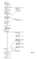
- FIG. 32 shows a flowchart with steps that can be applied when using the system according to the invention.
- the steps are up to here based on the FIGS. 1 to 22 listed procedure, wherein numbers are given to the blocks of the sequence steps, which illustrate the numbers of these steps FIGS. 1 to 22 in the previous description of the figures.
- the steps 23 to 30 listed in the right-hand branches are optionally additional or alternatively possible steps within the process that can be carried out in the illustrated process steps. These steps 23 to 30 will be described below with reference to these steps FIGS. 23 to 30 described.
- Fig. 23 shows the prepared situation models. Their production takes place as standard with dental plaster of class 3.
- FIG. 24 The models of upper jaw and lower jaw base are shown in the articulator. Positioning with the Centric Tray allows positioning of the maxilla and mandible.
- a receptacle / interface for the registration joint for skull / joint-related assignment of the upper and lower jaw base is a receptacle / interface for the registration joint for skull / joint-related assignment of the upper and lower jaw base.
- the registration element itself can be exchanged.
- Fig. 27 shows a transfer sheet system. If the transfer sheet system is aligned with the patient, the locking screws are fixed to the registration joint.
- Fig. 28 shows the situation when setting on the patient.
- the individual position of the registration joint is digitized by scanning.
- the position of upper and lower jaw base patients can be individually reproduced in the virtual articulator.
- Fig. 29 It is shown how in a CAD / CAM-controlled production machine from a block of the constructed Einprobeanalysis is made in the erosive process. The denture teeth are then glued provisionally in the cavities.
- the entire try-in prosthesis (denture base body including denture teeth) can be manufactured in one piece.
- the permanent dental prosthesis or another Einprobe body can be made.
- the gingiva parameters defined in the data processing device are automatically taken into account during production of the prosthetic teeth. Subsequent reduction of the tooth length is not necessary with this method.
Landscapes
- Health & Medical Sciences (AREA)
- Oral & Maxillofacial Surgery (AREA)
- Life Sciences & Earth Sciences (AREA)
- Veterinary Medicine (AREA)
- Epidemiology (AREA)
- Animal Behavior & Ethology (AREA)
- General Health & Medical Sciences (AREA)
- Public Health (AREA)
- Dentistry (AREA)
- Engineering & Computer Science (AREA)
- Manufacturing & Machinery (AREA)
- Biomedical Technology (AREA)
- Biophysics (AREA)
- Dental Prosthetics (AREA)
- Dental Tools And Instruments Or Auxiliary Dental Instruments (AREA)
- Wind Motors (AREA)
Abstract
Description
Die Erfindung betrifft ein Verfahren zum Aufbau einer Dentalprothese, bei dem die Formen von Oberkiefer- und Unterkieferbasis mit plastischem Material mit Standardabformlöffeln oder mit individualisierten Abformlöffeln aufgenommen werden, die auf Grundlage einer vorhergehenden Erfassung der Formen mit Standardformlöffeln oder durch Erfassung der Formen durch digitales Scannen und/oder fototechnische Erfassung individuell an den Kiefer des Patenten angepasst hergestellt worden sind, bei der Aufnahme der Formen von Oberkiefer- und Unterkieferbasis die Lage der Okklusionsebene mit einem Okklusionom durch Ausrichten parallel zur Bipupillarlinie und zur Camperschen Ebene relativ zu Oberkiefer- und Unterkieferbasis erfasst und digital gespeichert wird, die Formen der in dem plastischen Material aufgenommenen Oberkiefer- und Unterkieferbasis digitalisiert und in einer Datenverarbeitungseinrichtung als digitales Prothesenmodell gespeichert werden, die Oberkiefer- und Unterkiefer-Prothesenbasen nach Maßgabe des digitalen Prothesenmodells aus Dentalmaterialien durch abtragende oder aufbauende Verfahren erstellt werden.The invention relates to a method for constructing a dental prosthesis, in which the forms of upper and lower jaw base are taken up with plastic material with standard impression trays or with individualized impression trays, based on a previous detection of the forms with standard trays or by recording the forms by digital scanning and or photographing detection individually adapted to the jaw of the patent, when recording the maxillary and mandibular base shapes, detects and digitally locates the occlusal plane with an occlusionoma by aligning parallel to the bipupillary line and Camper's plane relative to the maxillary and mandibular bases is stored, the shapes of the upper and lower jaw bases accommodated in the plastic material are digitized and stored in a data processing device as a digital prosthesis model, the maxillary and mandibular prostheses ba according to the digital prosthesis model from dental materials by ablative or constructive procedures are created.
Die Erfindung betrifft ferner ein System zum Aufbau einer Dentaltotalprothese, mitThe invention further relates to a system for constructing a dental total prosthesis, with
Standardabformlöffeln oder individualisierten Abformlöffeln zum Aufnehmen der Formen von Oberkiefer- und Unterkieferbasis mit plastischem Material, wobei die individualisierten Abformlöffeln auf Grundlage einer vorhergehenden Erfassung der Formen mit Standardformlöffeln oder durch Erfassung der Formen durch digitales Scannen und/oder fototechnische Erfassung individuell an den Kiefer des Patenten angepasst hergestellt worden sind,
einem Okklusionom zum Erfassen der Lage der Okklusionsebene durch Ausrichten parallel zur Bipupillarlinie und zur Camperschen Ebene bei der Aufnahme der Formen von Oberkiefer- und Unterkieferbasis und einem Speicher zur Speicherung der digitalisierten Lage der Okklusionsebene relativ zur von Oberkiefer- und Unterkieferbasis,
einer Abtastungseinrichtung zum Erfassen und Digitalisieren der Formen der in dem plastischen Material aufgenommenen Oberkiefer- und Unterkieferbasis,
einer Datenverarbeitungseinrichtung zum Speichern der digitalisierten Formen von Oberkiefer- und Unterkieferbasis als digitales Prothesenmodell,
einem Fertigungsgerät zum Erstellen die Oberkiefer- und Unterkiefer-Prothesenbasen nach Maßgabe des digitalen Prothesenmodells aus Dentalmaterialien unter Steuerung der Datenverarbeitungseinrichtung durch abtragende oder aufbauende Verfahren.Standard impression trays or individualized impression trays for accommodating the upper and lower jaw base molds with plastic material, the individualized impression trays being individually adapted to the jaw of the patent based on previous detection of the forms with standard trays or by capturing the forms by digital scanning and / or photographic detection have been produced,
an occlusionoma for detecting the position of the occlusal plane by aligning it in parallel to the bipupillary line and the camper's plane in accommodating the maxillary and mandibular base shapes and a memory for storing the digitized position of the occlusal plane relative to the maxillary and mandibular base;
a scanning device for detecting and digitizing the shapes of the upper jaw and lower jaw base accommodated in the plastic material,
a data processing device for storing the digitized forms of maxilla and mandibular base as a digital prosthesis model,
a production device for creating the upper jaw and lower jaw prosthesis bases in accordance with the digital prosthesis model of dental materials under the control of the data processing device by ablating or constructive methods.
Ein frühes Verfahren und System in dieser Richtung ist zum Beispiel aus dem Artikel "
Ein Verfahren nach dem Oberbegriff von Patentanspruch 1 ist aus
Es ist Aufgabe der vorliegenden Erfindung, ein verbessertes Verfahren und ein verbessertes System zum Aufbau einer Dentalprothese anzugeben, bei dem ein digitales Prothesenmodell mit verbesserter Positionierung der Zahnaufstellung erzeugt werden kann. Ferner soll eine zielsicherere Auswahl eines optimalen Frontzahnbogens für die Prothese ermöglicht werden.It is an object of the present invention to provide an improved method and an improved system for constructing a dental prosthesis, in which a digital prosthesis model with improved positioning of the tooth set-up can be produced. Furthermore, a more targeted selection of an optimal anterior arch for the prosthesis should be made possible.
Zur Lösung dieser Aufgabe dient das Verfahren mit den Merkmalen des Patentanspruchs 1 und das System mit den Merkmalen des Patentanspruchs 11. Vorteilhafte Ausführungsformen sind in den Unteransprüchen angegeben.To achieve this object, the method with the features of claim 1 and the system with the features of
Bei dem erfindungsgemäßen Verfahren steht ein Satz von oberen oder unteren Standard-Frontzahnbögen zur Verfügung, wobei in dem Satz Standard-Frontzahnbögen mit verschiedenen Frontzahngrößen und Frontzahnformen enthalten sind. In einer Datenbank sind für jeden Frontzahnbogen aus dem bereitgestellten Satz von Standard-Frontzahnbögen deren Formdaten gespeichert, die eine dreidimensionale räumliche Beschreibung der Zähne des Frontzahnbogens darstellen. Beim Aufnehmen der Formen von Ober- und Unterkieferbasis mit plastischem Material in den Abformlöffeln wird ein Frontzahnbogen aus dem bereitgestellten Satz von Standard-Frontzahnbögen ausgewählt, der am besten zu der Situation im Kiefer des Patienten passt. Dieser ausgewählte Standard-Frontzahnbogen wird dann an dem Abformlöffel positioniert, so dass er die gewünschte Stellung im Kiefer erhält und in dieser Position an dem Abformlöffel befestigt. Zur Bildung eines Ausgangspunktes für das digitale Prothesenmodell werden die Formen der in dem plastischen Material aufgenommenen Oberkiefer- und Unterkieferbasis mit dem daran befestigten Frontzahnbogen in registrierter Bissstellung durch Scannen digitalisiert und gespeichert. Aus der Datenbank mit den Frontzahnbogen-Formdaten des Satzes von Standard-Frontzahnbögen werden dann die Frontzahnbogen-Formdaten abgerufen, die zu dem ausgewählten Standard-Frontzahnbogen gehören. Diese werden nun in dem digitalen Prothesenmodell räumlich so positioniert, dass sich eine möglichst geringe Abweichung zur Position des tatsächlich eingescannten, an dem Abformlöffel befestigten ausgewählten Frontzahnbogens ergibt. Mit anderen Worten wird in dem digitalen räumlichen Modell der Prothese die Positionierung der importierten Frontzahnbogen-Formdaten des ausgewählten Standard-Frontzahnbogens durch Verschieben und Verschwenken so lange variiert, bis eine minimale Abweichung gegenüber dem eingescannten Frontzahnbogen erreicht ist.In the method according to the invention, a set of upper or lower standard anterior archs is available, wherein the set contains standard anterior dental archs with different anterior tooth sizes and anterior tooth shapes. In a database For each anterior arch, from the set of standard anterior dental archs provided, their shape data is stored, representing a three-dimensional spatial description of the teeth of the anterior arch. When picking up the upper and lower jaw base molds with plastic material in the impression trays, an anterior arch is selected from the provided set of standard anterior archs that best fits the patient's jaw situation. This selected standard anterior arch is then positioned on the impression tray so that it receives the desired position in the jaw and secured in position on the impression tray. To form a starting point for the digital prosthesis model, the shapes of the maxillary and mandibular bases received in the plastic material with the anterior arch attached thereto are digitized and stored in registered bite position by scanning. From the anterior arch form data database of the set of standard anterior archs, the anterior arch shape data associated with the selected standard anterior arch is then retrieved. These are now spatially positioned in the digital prosthesis model in such a way that the smallest possible deviation from the position of the actual scanned arch attached to the impression tray results. In other words, in the digital spatial model of the prosthesis, the positioning of the imported anterior arch form data of the selected standard anterior arch is varied by displacement and pivoting until a minimum deviation from the scanned anterior arch is achieved.
Auf diese Weise ist es dem Zahntechniker oder Zahnarzt möglich, beim Abformen der Formen von Oberkiefer- und Unterkieferbasis aus einem vorliegenden Satz von Standard-Frontzahnbögen verschiedene auszuprobieren und einen am besten geeigneten auszuwählen. Dieser wird dann in seiner gewünschten Position an dem Abformlöffel befestigt, so dass seine spätere Position in dem digitalen Prothesenmodell festgelegt werden kann. Durch den Import der Standard-Frontzahnbogen-Formdaten des ausgewählten Standard-Frontzahnbogens aus der Datenbank wird eine höhere Genauigkeit des digitalen Prothesenmodells ermöglicht.In this way, it is possible for the dental technician or dentist to try out different ones of a given set of standard anterior archs and to select one that is most suitable when molding the shapes of maxillary and mandibular base. This is then fastened in its desired position on the impression tray, so that its later Position can be set in the digital prosthesis model. By importing the standard anterior arch form data of the selected standard anterior arch from the database, a higher accuracy of the digital prosthesis model is enabled.
Das Verfahren kann zum Beispiel von einem Zahnarzt oder Zahntechniker ausgeführt werden, der die Abformungen vornimmt und der die Abformlöffel mit den in dem plastischen Material aufgenommenen Formen von Oberkiefer- und Unterkieferbasis und dem daran befestigten Frontzahnbogen in registrierter Bissstellung herstellt. Die Abformlöffel mit den aufgenommenen Formen und den daram befestigten Frontzahnbögen können dann in ein Zahnlabor gebracht werden, wo diese Form durch Scannen digitalisiert und gespeichert wird, um einen Ausgangspunkt für das digitale Prothesenmodell zu bilden. In dem Zahnlabor kann das digitale Prothesenmodell dann automatisch in der Datenverarbeitungseinrichtung durch Abruf von Formdaten für Standard-Frontzahnbögen und Backenzahnreihen komplettiert und auch interaktiv von dem Benutzer durch Eingaben und weiteren Formgebungen sukzessive verbessert werden. Das so erhaltene endgültige digitale Prothesenmodell kann dann zum Beispiel in einem CAM-Verfahren zum Fräsen der Prothesenbasen aus Kunststoffblöcken verwendet werden.The method may be performed, for example, by a dentist or dental technician who makes the impressions and who makes the impression trays in registered bite position with the maxillary and mandibular base forms and the anterior arch secured thereto in the plastic material. The impression trays with the recorded forms and the anterior cusps attached thereto can then be transferred to a dental laboratory, where this form is digitized and stored by scanning to form a starting point for the digital prosthesis model. In the dental laboratory, the digital prosthesis model can then be automatically completed in the data processing device by retrieving form data for standard anterior teeth and molar teeth and also be successively improved by the user interactive inputs and other shapes. The final digital prosthesis model thus obtained can then be used, for example, in a CAM method for milling the denture bases made of plastic blocks.
In einer bevorzugten Ausführungsform kann die Datenverarbeitungseinrichtung dazu eingerichtet sein, aus der Datenbank einen zu dem ausgewählten Standard-Frontzahnbogen für Ober- oder Unterkiefer passenden Antagonisten-Standard-Frontzahnbogen in Form von digitalen Antagonisten-Standard-Frontzahnbogen-Formdaten abzurufen und mit den Daten der zugehörigen Kieferbasis in dem digitalen Prothesenmodell so zu positionieren, dass eine optimale Lage zu dem ausgewählten Standard-Frontzahnbogen erzielt wird, dessen Formdaten bereits zuvor aus der Datenbank in das digitale Prothesenmodell integriert worden sind.In a preferred embodiment, the data processing device may be configured to retrieve from the database a standard antagonist standard anterior arch suitable for the selected standard anterior or mandibular arch in the form of digital antagonist standard anterior arch shape data and the data associated therewith To position the jaw base in the digital prosthesis model in such a way that an optimal position is achieved for the selected standard anterior arch, the shape data of which has already been obtained have been integrated from the database into the digital prosthesis model.
In einer weiteren bevorzugten Ausführungsform werden von der Datenverarbeitungseinrichtung nach Integration der Standard-Frontzahn-Formdaten und gegebenenfalls Antagonisten-Standard-Frontzahn-Formdaten mit den digitalisierten Daten der zugehörigen Kieferbasis automatisch eine oder mehrere zu dem Frontzahnbogen passende Backenzahnreihen zur Auswahl angeboten und nach Auswahl durch den Benutzer diese beschreibende digitale Backenzahnreihen-Formdaten aus der Datenbank abgerufen und mit den digitalisierten Kiefernbasisdaten im Anschluss passend zu den bereits integrierten Standard-Frontzahnbogen-Formdaten in das digitale Prothesenmodell eingepasst wird.In a further preferred embodiment, one or more molar rows matching the anterior arch are automatically offered for selection by the data processing device after integration of the standard anterior mold data and optionally antagonist standard anterior mold data with the digitized data of the associated mandibular base and selected by the user This descriptive digital molar row shape data is retrieved from the database and fitted with the digitized pine base data subsequent to the already integrated standard anterior arch shape data into the digital prosthesis model.
In einer bevorzugten Ausführungsform erzeugt die Datenverarbeitungseinrichtung eine graphische Darstellung des digitalen Prothesenmodells und bringt diese auf einem Bildschirm zur Anzeige. Die Datenverarbeitungseinrichtung stellt Programmfunktionen bereit, mit denen das digitale Prothesenmodell durch Einwirken auf die graphische Darstellung manipuliert werden kann. Insbesondere wird ein digitales Wachsmesser als Programmfunktion bereitgestellt, um das Design des Zahnfleisches und der Prothesenbasenoberflächen mit dem digitalen Wachsmesser in der graphischen Darstellung des digitalen Prothesenmodells zu gestalten und die so vorgenommenen Gestaltungen in das digitale Prothesenmodell zu übernehmen.In a preferred embodiment, the data processing device generates a graphical representation of the digital prosthesis model and displays it on a screen for display. The data processing device provides program functions with which the digital prosthesis model can be manipulated by acting on the graphical representation. In particular, a digital wax gauge is provided as a program feature to shape the design of the gum and prosthetic base surfaces with the digital wax gauge in the digital prosthesis model plot and incorporate the designs so made into the digital prosthetic model.
In einer bevorzugten Ausführungsform stellt die Datenverarbeitungseinrichtung eine Mehrzahl von vorgegebenen Oberflächentexturen zur Auswahl bereit, die nach Auswahl auf gewünschte Bereiche der Oberflächen des digitalen Prothesenmodells übertragbar sind.In a preferred embodiment, the data processing device provides a plurality of predetermined surface textures for selection, which can be transferred to desired areas of the surfaces of the digital prosthesis model after selection.
In einer bevorzugten Ausführungsform wird von der Datenverarbeitungseinrichtung wenigstens ein Gingiva-Parameter zur Spezifizierung abgefragt. Darunter ist wenigstens einer der folgenden Gingiva-Parameter: gingivale Fassung der Zahnlängen der aufgestellten Zähne (d.h. die Tiefe, mit der die Zahnbasis in die Kavität in die Prothesenbasis hineinreicht), Mindestwandstärke von Oberkiefer- und Unterkieferbasis (d.h. eine minimale Dicke, die die Prothesenbasis an jedem Punkt haben muss), Oberflächentexturparameter der Gaumenoberfläche und Geometrieparameter des Übergangsbereichs von Prothesenoberfläche zum Zahn (d.h. die Innenwand der Kavität muss nicht in einer scharfen Kante in die oben anschließende Prothesenbasenoberfläche übergehen, sondern der Übergangsbereich kann abgerundet sein); diese eingegebenen Gingiva-Geometrieparameter werden in das digitale Prothesenmodell übernommen.In a preferred embodiment, at least one gingival parameter is requested for specification by the data processing device. Among these is at least one of the following gingival parameters: gingival setting of the toothed tooth lengths (ie, the depth with which the tooth base extends into the cavity into the prosthesis base), minimum wall thickness of the maxillary and mandibular base (ie, a minimum thickness that defines the denture base at any point), surface texture parameters of the palate surface and geometric parameters of the transition region from prosthetic surface to tooth (ie, the inner wall of the cavity does not have to transition at a sharp edge into the prosthesis base surface adjacent to it, but the transition region may be rounded); these entered gingival geometry parameters are incorporated into the digital prosthesis model.
In einer bevorzugten Ausführungsform werden von der Datenverarbeitungseinrichtung wenigstens ein Zahnkavitätsparameter zur Spezifizierung abgefragt, wozu die Bereite des Klebespaltes zwischen Innenwand der Zahnkavität und der eingeführten Zahnbasis und Ort und Anzahl von Abstandshaltern an der Innenwand der Zahnkavität gehören, mit denen die Zahnbasis definiert positioniert in der Zahnkavität gehalten werden, um überall einen Klebespalt in gewünschter Breite zwischen Innenwänden der Zahnkavität und Zahnbasis zu gewährleisten; die spezifizierten Zahnkavitätsparameter werden für alle Zahnkavitäten in das digitale Prothesenmodell übernommen.In a preferred embodiment, the data processing device interrogates at least one tooth cavity parameter for specification, including the width of the bonding gap between the inner wall of the dental cavity and the inserted tooth base, and the location and number of spacers on the inner wall of the dental cavity with which the tooth base is positioned in the tooth cavity be held to ensure everywhere a bonding gap in the desired width between inner walls of the tooth cavity and tooth base; The specified tooth cavity parameters are adopted for all dental cavities in the digital prosthesis model.
In einer bevorzugten Ausführungsform wird in der Datenverarbeitungseinrichtung, wenn bei der Berechnung der Kavitäten für konfektionierte Kunststoffzähne festgestellt wird, dass die verbleibende Wandstärke der Prothesenbasis unter der Kavität eine vorgegebene Mindestwandstärke unterschreiten würde, berechnet und gespeichert, auf welche Länge der Kunststoffzahn zu reduzieren ist, um die vorgegebene Mindestwandstärke unter der Kavität zu erhalten. Die Kavität wird dann an die reduzierte Länge des Kunststoffzahns angepasst in dem digitalen Prothesenmodell gespeichert. Ferner wird der Kunststoffzahn in einer Fräseinrichtung unter Steuerung der Datenverarbeitungseinrichtung auf die gespeicherte reduzierte Länge des Kunststoffzahns verkürzt.In a preferred embodiment, if it is determined in the calculation of the cavities for prefabricated plastic teeth, that the remaining wall thickness of the prosthesis base under the cavity would fall below a predetermined minimum wall thickness, then calculated and stored in the data processing device to which length the plastic tooth is to be reduced the predetermined minimum wall thickness below to get the cavity. The cavity is then stored adapted to the reduced length of the plastic tooth in the digital prosthesis model. Furthermore, the plastic tooth is shortened in a milling device under the control of the data processing device to the stored reduced length of the plastic tooth.
In einer bevorzugten Ausführungsform stellt die Datenverarbeitungseinrichtung ein Auswahlmenü für künstliche Zähne aus unterschiedlichen Materialtypen bereit, in dem für jede Zahnposition eine Materialauswahl aus Dentalmaterialien möglich ist. Mögliche Dentalmaterialien sind PMMA, Komposit, Zirkoniumdioxid, Lithiumdisilikat, und Dentalkeramik. In der Datenverarbeitungseinrichtung wird dann der ausgewählte Materialtyp in dem digitalen Prothesenmodell gespeichert.In a preferred embodiment, the data processing device provides a selection menu for artificial teeth made of different types of material, in which a material selection from dental materials is possible for each tooth position. Possible dental materials are PMMA, composite, zirconium dioxide, lithium disilicate, and dental ceramics. The selected material type is then stored in the digital prosthesis model in the data processing device.
In einer bevorzugten Ausführungsform wird zur Bestimmung der Lage der Okklusionsebene ein Okklusionom verwendet, das einen inneren Bissbogen und einen über Gelenke daran angebrachten äußeren Bogen aufweist. Der innere Bogen wird zwischen die Standardabformlöffel oder die individualisierten Abformlöffel eingeführt. Wahlweise kann das Okklusionom über eine Schnittstelle an dem oberen und/unteren Abformlöffel befestigt werden. Dann wird der äußere Bogen durch Verschwenken der Gelenke parallel zur Camperschen Ebene und zur Bipupillarlinie eingestellt. Die sich ergebenden Abweichungen der Parallelität des inneren Bissbogens zu dem ausgerichteten äußeren Bogen werden an einer Skala an den Gelenken abgelesen und gespeichert.In a preferred embodiment, to determine the position of the occlusal plane, an occlusionoma is used which has an inner bite bow and an outer arch attached thereto via joints. The inner bow is inserted between the standard impression trays or the customized impression trays. Optionally, the occlusionoma can be attached to the upper and / or lower impression tray via an interface. Then the outer arch is adjusted by pivoting the joints parallel to the Camper's plane and the bipupillary line. The resulting deviations of the parallelism of the inner bite sheet from the aligned outer sheet are read from a scale at the joints and stored.
Die Erfindung schafft ferner ein System zum Aufbau einer Dentaltotalprothese, mitThe invention further provides a system for constructing a dental total prosthesis, with
Standardabformlöffeln oder individualisierten Abformlöffeln zum Aufnehmen der Formen von Oberkiefer- und Unterkieferbasis mit plastischem Material, wobei die individualisierten Abformlöffeln auf Grundlage einer vorhergehenden Erfassung der Formen mit Standardformlöffeln oder durch Erfassung der Formen durch digitales Scannen und/oder fototechnische Erfassung individuell an den Kiefer des Patenten angepasst hergestellt worden sind,
einem Okklusionom zum Erfassen der Lage der Okklusionsebene durch Ausrichten parallel zur Bipupillarlinie und zur Camperschen Ebene bei der Aufnahme der Formen von Oberkiefer- und Unterkieferbasis und einem Speicher zur Speicherung der digitalisierten Lage der Okklusionsebene relativ zur Oberkiefer- und Unterkieferbasis,
einer Abtastungseinrichtung zum Erfassen und Digitalisieren der Formen der in dem plastischen Material aufgenommenen Oberkiefer- und Unterkieferbasis,
einer Datenverarbeitungseinrichtung zum Speichern der digitalisierten Formen von Oberkiefer- und Unterkieferbasis als digitales Prothesenmodell,
einem Fertigungsgerät zum Erstellen der Oberkiefer- und Unterkiefer-Prothesenbasen nach Maßgabe des digitalen Prothesenmodells aus Dentalmaterialien unter Steuerung der Datenverarbeitungseinrichtung durch abtragende oder aufbauende Verfahren,
dadurch gekennzeichnet, dass
ein Satz von oberen oder unteren Standard-Frontzahnbögen zur Auswahl und Mittel zum Befestigen eines ausgewählten Standard-Frontzahnbogens in der gewünschten Position an dem Abformlöffel mit dem darin in dem plastischen Material abgeformten Ober- oder Unterkieferboden vorhanden sind,
die Abtastungseinrichtung dazu eingerichtet ist, zur Bildung eines Ausgangspunkts für das digitale Prothesenmodell die Formen der in dem plastischen Material aufgenommenen Oberkiefer- und Unterkieferbasis mit dem daran befestigtem Frontzahnbogen in registrierter Bissstellung durch Scannen zu digitalisieren und zu speichern,
die Datenverarbeitungseinrichtung dazu eingerichtet ist, aus einer Datenbank, die digitale Standard-Frontzahnbogen-Formdaten für alle Standard-Frontzahnbögen enthält, die den ausgewählten Standard-Frontzahnbogen beschreibenden Standard-Frontzahnbogen-Formdaten abzurufen und mit den Daten der zugehörigen Kieferbasis in dem digitalen Prothesenmodell so zu integrieren, dass die Position der digitalen Standard-Frontzahnbogen-Formdaten relativ zu den digitalisierten Kieferbasisdaten möglichst gut mit der Position des an dem Abformlöffel befestigen Standard-Frontzahnbogens relativ zu der abgeformten Kieferbasis übereinstimmt.Standard impression trays or individualized impression trays for holding the upper and lower jaw base molds with plastic material, the individualized impression trays based on a previous registration of the molds with standard mold spoons or by detecting the molds by digital scanning and / or photographic recording individually adapted to the jaw of the patent,
an occlusionoma for detecting the position of the occlusal plane by aligning it in parallel with the bipupillary line and the camper's plane in accommodating the maxillary and mandibular base shapes and a memory for storing the digitized location of the occlusal plane relative to the maxillary and mandibular base;
a scanning device for detecting and digitizing the shapes of the upper jaw and lower jaw base accommodated in the plastic material,
a data processing device for storing the digitized forms of maxilla and mandibular base as a digital prosthesis model,
a production device for producing the upper jaw and lower jaw prosthesis bases in accordance with the digital prosthesis model from dental materials under the control of the data processing device by ablative or constructive methods,
characterized in that
a set of upper or lower standard anterior archs for selection and means for securing a selected standard anterior arch in the desired position on the impression tray with the upper or lower jaw formed therein in the plastic material;
the scanning device is adapted to digitize and store the shapes of the maxillary and mandibular bases received in the plastic material with the anterior arch attached thereto in registered bite by scanning to form a starting point for the digital prosthesis model,
the data processing device is adapted to retrieve from a database containing standard digital anterior arch shape data for all standard anterior teeth, the standard anterior arch shape data describing the selected standard anterior arch and to associate with the data of the associated jaw base in the digital prosthesis model integrate that position of the standard digital anterior arch shape data relative to the digitized jaw base data as closely as possible to the position of the standard anterior dental arch attached to the impression tray relative to the molded jaw base.
In einer bevorzugten Ausführungsform des Systems ist die Datenverarbeitungseinrichtung dazu eingerichtet, für den ausgewählten Standard-Frontzahnbogen für Ober- oder Unterkiefer aus der Datenbank einen dazu passenden Antagonisten-Standard-Frontzahnbogen in Form von digitalen Antagonisten-Frontzahnbogen-Formdaten abzurufen und in das digitale Modell der zugehörigen Kieferbasis in dem digitalen Prothesenmodell so einzuführen, dass eine optimale Passung mit dem ausgewählten Standard-Frontzahnbogen erzielt wird.In a preferred embodiment of the system, the data processing device is set up to retrieve a matching antagonist standard anterior arch in the form of digital antagonist anterior arch form data for the selected standard anterior or mandibular anterior arch from the database and into the digital model of the associated jaw base in the digital prosthesis model so as to achieve an optimal fit with the selected standard anterior arch.
In einer bevorzugten Ausführungsform des Systems ist die Datenverarbeitungseinrichtung dazu eingerichtet, nach Integration der Standard-Frontzahnbogen-Formdaten und gegebenenfalls der Antagonisten-Standard-Frontzahnbogen-Formdaten in das digitale Prothesenmodell eine oder mehrere in der Datenbank als zu dem ausgewählten Standard-Frontzahnbogen passend charakterisierte Backenzahnreihen zur Auswahl anzubieten. Nach Auswahl der abgerufenen entsprechenden digitalen Backenzahnreihen-Formdaten aus der Datenbank werden diese in das digitale Prothesenmodell passend zu den bereits integrierten Standard-Frontzahnbogen-Formdaten eingepasst.In a preferred embodiment of the system, after integration of the standard anterior arch form data and optionally the antagonist standard anterior arch form data into the digital prosthesis model, the data processing device is adapted to characterize one or more in the database as appropriate to the selected standard anterior arch To offer molar rows to choose from. After selecting the retrieved corresponding digital molar row form data from the database, these are fitted into the digital prosthesis model matching the already integrated standard anterior arch form data.
In einer bevorzugten Ausführungsform des Systems weist dieses eine graphische Anzeige auf und ist die Datenverarbeitungseinrichtung dazu eingerichtet, eine graphische Darstellung des digitalen Prothesenmodells auf der Anzeige anzuzeigen. Von der Datenverarbeitungseinrichtung wird ein digitales Wachsmesser als Programmfunktion bereitgestellt, um einem Benutzer das Design des Zahnfleisches und der Prothesenbasenoberflächen mit dem digitalen Wachsmesser in der graphischen Anzeige des digitalen Prothesenmodells zu ermöglichen. Die in der graphischen Anzeige mit dem digitalen Wachsmesser vom Benutzer eingefügten Gestaltungen des Zahnfleisches und der Prothesenbasenoberflächen werden von der Datenverarbeitungseinrichtung in das digitale Prothesenmodell übernommen. In einer bevorzugten Ausführungsform des Systems ist die Datenverarbeitungseinrichtung dazu eingerichtet, mehrere vorgegebene Oberflächentexturen zur Auswahl bereitzustellen und diese nach Auswahl durch den Benutzer auf von dem Benutzer ausgewählte Bereiche der Oberflächen des digitalen Prothesenmodells übertragbar zu machen und diese in das digitale Prothesenmodell zu übernehmen.In a preferred embodiment of the system, the latter has a graphic display and the data processing device is set up to display a graphical representation of the digital prosthesis model on the display. The data processing device provides a digital wax gauge as a program function to allow a user to design the gum and prosthetic base surfaces with the digital wax gauge in the digital prosthesis model graphic display. The gum and prosthetic base surface designs inserted in the user's digital wax gauge graphical display are incorporated into the digital prosthetic model by the data processing device. In a preferred embodiment of the system, the data processing device is set up to provide a plurality of predefined surface textures for selection and to make these transferable to user-selected areas of the surfaces of the digital prosthesis model and to incorporate these into the digital prosthesis model.
In einer bevorzugten Ausführungsform des Systems ist die Datenverarbeitungseinrichtung dazu eingerichtet, wenigstens einen Gingiva-Parameter zur Spezifizierung abzufragen, wozu wenigstens einer der folgenden Parameter gehört: Gingivale Fassung der Zahnlängen der aufgestellten Zähne, Mindestwandstärke von Ober- und Unterkieferbasis, Oberflächentexturparameter der Gaumenoberfläche und Geometrieparameter des Übergangsbereichs von Prothesenbasiskörper zum Zahn, wobei die Datenverarbeitungseinrichtung dazu eingerichtet ist, eingegebene Gingiva-Parameter in das digitale Prothesenmodell zu übernehmen.In a preferred embodiment of the system, the data processing device is adapted to interrogate at least one gingival parameter for specification, including at least one of the following parameters: gingival version of the tooth length of the teeth, minimum wall thickness of the upper and lower jaw, surface texture of the palate surface, and geometry parameter of the Transition region of denture base body to the tooth, wherein the data processing device is adapted to take entered gingival parameters in the digital prosthesis model.
In einer bevorzugten Ausführungsform des Systems ist die Datenverarbeitungseinrichtung dazu eingerichtet, wenigstens einen Zahnkavitätsparameter zur Spezifizierung durch den Benutzer abzufragen, wobei zu den Zahnkavitätsparametern die Breite des Klebespaltes zwischen Innenwand der Zahnkavität und eingeführter Zahnbasis und Ort und Anzahl von Abstandshaltern an der Innenwand der Zahnkavität zur definierten Positionierung der Zahnbasis des eingeführten Zahns mit einem gleichmäßig breiten Klebespalt gehören, und die spezifizierten Zahnkavitätsparameter für alle Zahnkavitäten in das digitale Prothesenmodell zu übernehmen.In a preferred embodiment of the system, the data processing device is adapted to interrogate at least one dental cavity parameter for specification by the user, wherein the width of the adhesive gap between inner wall of the dental cavity and inserted dental base and location and number of spacers on the inner wall of the dental cavity are defined for the dental cavity parameters Positioning of the tooth base of the inserted tooth with a uniformly wide adhesive gap belong, and to adopt the specified Zahnkavitätsparameter for all dental cavities in the digital prosthesis model.
In einer bevorzugten Ausführungsform des Systems ist die Datenverarbeitungseinrichtung dazu eingerichtet, bei der Berechnung der Kavitäten für konfektionierte Kunststoffzähne festzustellen, ob die verbleibende Wandstärke der Prothesenbasis unter der Kavität eine vorgegebene Mindestwandstärke unterschreiten würde, und wenn ja, zu speichern, auf welche Länge der Kunststoffzahn zu reduzieren ist, um die vorgegebene Mindestwandstärke unter der Kavität einzuhalten, die Kavität an die reduzierte Länge des Kunststoffzahns anzupassen und in dem digitalen Prothesenmodell abzuspeichern. Anschließend kann die Datenverarbeitungseinrichtung mit diesen Daten eine Fräseinrichtung so steuern, dass der konfektionierte Kunststoffzahn auf die gespeicherte reduzierte Länge des Kunststoffzahns verkürzt wird.In a preferred embodiment of the system, the data processing device is adapted to determine when calculating the cavities for prefabricated plastic teeth, if the remaining wall thickness of the prosthesis base under the cavity would fall below a predetermined minimum wall thickness, and if so, to which length the plastic tooth to in order to maintain the predetermined minimum wall thickness under the cavity, to adapt the cavity to the reduced length of the plastic tooth and to store it in the digital prosthesis model. The data processing device can then use this data to control a milling device in such a way that the prefabricated plastic tooth is shortened to the stored reduced length of the plastic tooth.
In einer bevorzugten Ausführungsform des Systems ist die Datenverarbeitungseinrichtung weiter dazu eingerichtet, ein Auswahlmenü für künstliche Zähne aus unterschiedlichen Materialien bereitzustellen, in dem für jede Zahnposition eine Materialauswahl aus Dentalmaterial möglich ist, wobei die Datenverarbeitungseinrichtung weiter dazu eingerichtet ist, den ausgewählten Materialtyp bei der Berechnung der Kavitäten in den Prothesenbasiskörpern zu berücksichtigen.In a preferred embodiment of the system, the data processing device is further configured to provide a selection menu for artificial teeth made of different materials, in which a material selection of dental material is possible for each tooth position, wherein the data processing device is further adapted to take into account the selected material type in the calculation of the cavities in the prosthesis base bodies.
In einer bevorzugten Ausführungsform des Systems weist das Okklusionom einen inneren Bissbogen und einen über Gelenke daran angebrachten äußeren Bogen auf, der parallel zur Camperschen Ebene und parallel zur Bipupillarlinie auszurichten ist, wonach die sich ergebene Abweichung der Parallelität des inneren Bissbogens gegenüber dem ausgerichteten äußeren Bogen an Skalen an den Gelenken ablesbar ist.In a preferred embodiment of the system, the occlusionoma has an inner bite arch and an outer arch attached thereto via hinges which is to be aligned parallel to the Camper's plane and parallel to the bipupillary line, followed by the resulting deviation of the parallelism of the inner bite arch from the aligned outer arch Scales on the joints is readable.
Die Erfindung wird im Folgenden anhand eines Ausführungsbeispiels in den Figuren beschrieben, in denen:
-
Fig. 1 eine Draufsicht auf Standardabformlöffel für Oberkiefer- und Unterkieferbasis mit plastischem Material darin zeigt, -
Fig. 2 eine perspektivische Ansicht eines Centric Tray für eine Lagebestimmung von Oberkiefer und Unterkiefer zeigt, -
Fig. 3 eine Abtasteinrichtung zum Scannen der abgeformten Formen von Oberkiefer- und Unterkieferbasis zeigt, -
Fig. 4 die Formen von Oberkiefer- und Unterkieferbasis in einem virtuellen Artikulator zeigt, -
Fig. 5 perspektivische Ansichten der auf Basis der eingescannten Daten der aufgenommenen Formen von Oberkiefer- und Unterkieferbasis hergestellten individualisierten Abformlöffel zeigen, -
Fig. 6 eine perspektivische Ansicht eines individualisierten Abformlöffels bei dessen Herstellung in einer CAD/CAMgesteuerten Maschine auf Basis der eingescannten Daten der Formen von Oberkiefer- und Unterkieferbasis zeigt, -
Fig. 7 Draufsichten auf die fertig gestellten individualisierten Abformlöffel zeigt, -
Fig. 8 eine Ansicht eines individualisierten Abformlöffels beim Befüllen mit plastischem Material zeigt, -
Fig. 9a ) - c) perspektivische Ansichten eines Okklusionoms, des Okklusionoms bei der Bestimmung der Okklusionsebene und eine Detailansicht des Okklusionoms mit einer Skala zur Anzeige von Daten zur Lage der Okklusionsebene zeigen, -
Fig. 10 eine perspektivische Ansicht eines individualisierten Abformlöffels für den Oberkiefer bei der Zufügung eines ausgewählten Standard-Formzahnbogens zeigt, -
Fig. 11 eine Ansicht der individualisierten Abformlöffel nach der Kieferrelationsbestimmung mittels Stützregistrat zeigt, -
Fig. 12 eine Darstellung des digitalen Prothesenmodells bei der Integration der aus einer Datenbank abgerufenen Standard-Frontzahnbogenformdaten des ausgewählten Standard-Frontzahnbogens zeigt, -
Fig. 13 eine Darstellung des digitalen Prothesenmodells der Unterkieferbasis von oben zeigt, -
Fig. 14 eine perspektivische Detailansicht des digitalen Prothesenmodells bei der Integration von aus der Datenbank abgerufenen Backenzahnreihen in das digitale Prothesenmodell zeigt, -
Fig. 15 eine Draufsicht auf den Unterkiefer des digitalen Prothesenmodells bei der Einfügung von Backenzahnreihen zeigt, -
Fig. 16 eine perspektivische Darstellung des digitalen Prothesenmodells mit integrierten Zahnformdaten sämtlicher Zähne bei der Funktionskontrolle der Positionierung mit einem digitalen Artikulator zeigt, -
Fig. 17 perspektivische Darstellungen des digitalen Prothesenmodells beim Modellieren des Zahnfleisches mittels eines digitalen Wachsmessers zeigt, -
Fig. 18 eine Querschnittsansicht aus dem digitalen Prothesenmodell im Bereich einer Zahnkavität der Unterkieferbasis zeigt, -
Fig. 19 eine perspektivische Ansicht einer in der Fertigung befindlichen Kieferprothesenbasis mit einem auf Basis des digitalen Prothesenmodells gesteuerten CAD/CAM-Fertigungsgerät zeigt, -
Fig. 20 eine schematische Ansicht von konfektionierten Kunststoffzähnen bei der automatisch gesteuerten basalen Anpassung/Einkürzung zeigt, -
Fig. 21 perspektivische Ansichten beim Einsetzen von Prothesenzähnen in die Prothesenbasis zeigt, -
Fig. 22 eine perspektivische Ansicht der eingesetzten Dentalprothese bei der funktionellen und ästhetischen Kontrolle zeigt, -
Fig. 23 eine Draufsicht auf mit Dentalgips hergestellte Situationsmodelle von Oberkiefer- und Unterkieferbasis zeigt, -
Fig. 24 eine perspektivische Darstellung der Modelle von Oberkiefer- und Unterkieferbasis eingesetzt in einen Artikulator zeigt, -
Fig. 25 eine perspektivische Ansicht der Modelle im Artikulator nach Herstellung individualisierter Abformlöffel zeigt, -
Fig. 26 perspektivische Ansichten der hergestellten individualisierten Abformlöffel mit Schnittstelle zur Aufnahme des Transferbogensystems zeigt, -
Fig.27 eine perspektivische Ansicht eines Transferbogensystems zur Ausrichtung am Patienten zeigt; -
Fig. 28 eine perspektivische Ansicht des positionierten Transferbogensystems am Patienten zeigt, -
Fig. 29 eine perspektivische Ansicht bei der Herstellung des konstruierten Einprobekörpers in einem CAD/CAM-gesteuerten Fertigungsgerät aus einem Block zeigt, -
Fig. 30 eine perspektivische Darstellung des CAD/CAMgesteuerten Fertigungsgerätes bei der Fertigung der Prothesenzähne auf Grundlage der Daten aus dem digitalen Prothesenmodell zeigt, -
Fig. 31 eine perspektivische Darstellung der aus einem Block herausgearbeiteten Prothesenzähne zeigt und -
Fig. 32 eine perspektivische Darstellung von hergestellten Prothesenzähnen auf Basis des digitalen Prothesenmodells zeigt.
-
Fig. 1 a top view of standard impression tray for maxilla and mandibular base with plastic material therein shows -
Fig. 2 shows a perspective view of a centric tray for an orientation of upper jaw and lower jaw, -
Fig. 3 a scanning device for scanning the molded forms of maxilla and mandibular base, -
Fig. 4 shows the shapes of maxilla and mandibular base in a virtual articulator, -
Fig. 5 show perspective views of the individualized impression trays made on the basis of the scanned data of the recorded forms of maxilla and mandibular base, -
Fig. 6 a perspective view of an individualized impression tray when it is manufactured in a CAD / CAM controlled Machine based on the scanned data of the maxillary and mandibular base forms, -
Fig. 7 Showing top views of the finished individualized impression trays, -
Fig. 8 shows a view of an individualized impression tray when filled with plastic material, -
Fig. 9a c) show perspective views of an occlusionoma, the occlusion site in the determination of the occlusal plane and a detail view of the occlusionoma with a scale for displaying data on the position of the occlusal plane, -
Fig. 10 shows a perspective view of an individualized impression tray for the maxilla with the addition of a selected standard form of dental arch, -
Fig. 11 shows a view of the individualized impression trays according to the jaw relation determination by means of support registration, -
Fig. 12 Figure 12 shows a representation of the digital prosthesis model in the integration of the standard anterior arch form data retrieved from a database of the selected standard anterior arch, -
Fig. 13 shows a representation of the digital prosthesis model of the lower jaw base from above, -
Fig. 14 shows a perspective detailed view of the digital prosthesis model in the integration of molar rows retrieved from the database into the digital prosthesis model, -
Fig. 15 shows a plan view of the lower jaw of the digital prosthesis model in the insertion of molar teeth, -
Fig. 16 shows a perspective view of the digital prosthesis model with integrated tooth form data of all teeth in the functional check of positioning with a digital articulator, -
Fig. 17 shows perspective views of the digital prosthesis model when modeling the gums by means of a digital wax knife, -
Fig. 18 shows a cross-sectional view of the digital prosthesis model in the region of a tooth cavity of the lower jaw base, -
Fig. 19 3 shows a perspective view of a manufactured denture base with a CAD / CAM production device controlled on the basis of the digital prosthesis model, -
Fig. 20 a schematic view of prefabricated plastic teeth in the automatically controlled basal fitting / shortening shows -
Fig. 21 shows perspective views when inserting denture teeth into the denture base, -
Fig. 22 shows a perspective view of the dental prosthesis used in the functional and aesthetic control, -
Fig. 23 shows a plan view of denture-made situation models of maxilla and mandibular base, -
Fig. 24 shows a perspective view of the models of maxillary and mandibular base inserted into an articulator, -
Fig. 25 shows a perspective view of the models in the articulator after making individualized impression trays, -
Fig. 26 shows perspective views of the manufactured individualized impression trays with interface for receiving the transfer sheet system, -
Fig.27 shows a perspective view of a transfer sheet system for alignment with the patient; -
Fig. 28 shows a perspective view of the positioned transfer sheet system on the patient, -
Fig. 29 shows a perspective view in the manufacture of the constructed sample body in a CAD / CAM-controlled production unit from a block, -
Fig. 30 shows a perspective view of the CAD / CAM-controlled production device in the manufacture of denture teeth based on the data from the digital prosthesis model, -
Fig. 31 a perspective view of the worked out of a block denture teeth and shows -
Fig. 32 a perspective view of manufactured prosthetic teeth based on the digital prosthesis model shows.
Im Folgenden wird zunächst die Herstellung einer Dentalprothese mit einem erfindungsgemäßen Verfahren und System beschrieben, in denen individualisierte Abformlöffel zum Einsatz kommen.The production of a dental prosthesis with a method and system according to the invention will first be described below. in which individualized impression trays are used.
In
Diese aufgenommenen Formen von Oberkiefer- und Unterkieferbasis werden in einem in
In
Auf Grundlage des so zunächst gewonnenen digitalen Prothesenmodells werden, wie in
In
In
In
Der Satz von Standard-Frontzahnbögen kann zum Beispiel Frontzahnbögen mit unterschiedlichen Frontzahngrößen (klein-mittelgroß) und unterschiedlichen Frontzahnbogengrößen (weit-mitteleng) enthalten. Jeder Standard-Frontzahnbogen kann zum Beispiel sechs Frontzähne umfassen.For example, the set of standard anterior arch may contain anterior arch with different anterior tooth sizes (small-medium) and different anterior arch sizes (far-mid). For example, each standard anterior arch may include six anterior teeth.
In
Falls bei der Lagebestimmung der Okklusionsebene Abweichungen von der Nullposition der Skala registriert wurden, sind die abweichenden Werte in die Datenverarbeitungseinrichtung einzugeben. Die Position der Okklusionsebene passt sich entsprechend den Vorgaben an.If deviations from the zero position of the scale have been registered during the position determination of the occlusal plane, the deviating values must be entered into the data processing device. The position of the occlusal plane adapts to the specifications.
Der weitere Aufbau und die Verfeinerung des digitalen Prothesenmodells findet nun an der Datenverarbeitungseinrichtung statt, die eine Anzeige des räumlichen digitalen Prothesenmodells wie schematisch in
Zu dem physisch ausgewählten Standard-Frontzahnbogen, dessen Identifizierung in die Datenverarbeitungseinrichtung eingegeben ist, wird nun von der Datenverarbeitungseinrichtung aus einer Datenbank ein Datensatz mit digitalen Standard-Frontzahnbogen-Formdaten für den ausgewählten Standard-Frontzahnbogen abgerufen. Dieses digitale Modell des ausgewählten Standard-Frontzahnbogens wird dann in das digitale Prothesenmodell so integriert, dass die Position des abgerufenen digitalen Modells aus Standard-Frontzahnbogen-Formdaten relativ zu den digitalisierten Kieferbasisdaten möglichst gut zu der Position der eingescannten Daten des an dem Abformlöffel befestigten Standard-Frontzahnbogens in dem digitalen Prothesenmodell passt. Dies ist in
Die Datenverarbeitung ist dann weiter dazu eingerichtet, aus der Datenbank mit den digitalen Modellen für die Standard-Frontzahnbögen einen Antagonisten-Standard-Frontzahnbogen abzurufen, der zu dem ausgewählten Standard-Frontzahnbogen passt. Falls mehrere Antagonisten-Frontzahnbögen in der Datenbank als potentiell zu dem ausgewählten Standard-Frontzahnbogen passend deklariert sind, werden diese von der Datenverarbeitungseinrichtung zur Auswahl angezeigt. Anschließend werden die digitalen Modelldaten des ausgewählten Antagonisten-Standard-Frontzahnbogens 42 mit den digitalisierten Daten des digitalen Prothesenmodells der zugehörigen Kieferbasis so zusammengeführt, dass eine optimale Lage/Position mit dem bereits zuvor ausgewählten und in das digitale Prothesenmodell integrierten digitalen Daten des ausgewählten Standard-Frontzahnbogens 41 erzielt wird. Dies ist in
In
So werden aufeinanderfolgend die Zahndaten aller Zähne in ihrer Position in die digitale Prothese eingepasst. Eine Funktionskontrolle der Positionierung erfolgt mit dem digitalen Artikulator. Die Datenverarbeitungseinrichtung ist dazu eingerichtet, dabei funktionelle Störkontakte in der Okklusion sowie der Okklusionsbewegung zu erkennen und zu speichern. Störkontakte können später vom Anwender schleiftechnisch entfernt werden.Thus, successively the tooth data of all teeth are fitted in their position in the digital prosthesis. A functional check of the positioning is done with the digital articulator. The data processing device is set up to recognize and store functional interference contacts in the occlusion and the occlusion movement. Interference contacts can later be removed by the user by means of grinding technology.
Wie in
Ferner wird von der Datenverarbeitungseinrichtung eine Mehrzahl von vorgegebenen Oberflächentexturen zur Auswahl bereitgestellt, die der Anwender auswählen und auf ausgewählte Bereiche der Oberflächen des digitalen Prothesenmodells übertragen kann, wonach diese in das digitale Prothesenmodell übernommen werden.Furthermore, the data processing device provides a plurality of predefined surface textures for selection, which the user selects and transmits to selected regions of the surfaces of the digital prosthesis model can, after which these are taken over into the digital prosthesis model.
Zur weiteren Gestaltung der Gingiva werden von der Datenverarbeitungseinrichtung dem Anwender eine Anzahl von Gingiva-Parametern zur Spezifizierung angeboten. Dazu gehören:
- 1. gingivale Fassung der Zahnlängen der aufgestellten Zähne, d.h. die Tiefe der Kavität in der Kieferbasis, die die Zahnbasis aufnimmt,
- 2. Mindestwandstärke von Oberkiefer- und Unterkieferbasis, d.h. die minimale Stärke der unter einer Kavität verbleibenden Wanddicke der Basis,
- 3. Oberflächentexturparameter der Gaumenoberfläche, und
- 4. Geometrieparameter des Übergangsbereichs von Prothesenbasiskörper zum Zahn in der Kavität. Mit den letzteren Geometrieparametern kann der Anwender den Übergangsbereich von der Prothesenbasisoberfläche zu einer Kavität gestalten, zum Beispiel eine Abrundung vorsehen.
- 1. gingival version of the tooth lengths of the set-up teeth, ie the depth of the cavity in the jaw base, which accommodates the tooth base,
- 2. Minimum wall thickness of upper and lower jaw base, ie the minimum thickness of the wall thickness of the base remaining under a cavity,
- 3. Surface texture parameters of the palate surface, and
- 4. Geometry parameters of the transition region of denture base body to the tooth in the cavity. With the latter geometry parameters, the user can design the transition region from the denture base surface to a cavity, for example, provide a rounding.
Durch eine Abrundung oder Abschrägung am oberen Rand weitet sich die Kavität am oberen Rand leicht auf. Dadurch entsteht ein leicht erweiterter Rand um die Zahnbasis im Übergangsbereich zur Prothesenbasisoberfläche, wobei dieser erweiterte Übergangsbereich beim Einkleben der Kunstzähne mit Klebstoff gefüllt wird. Bei Verwendung von antibakteriellen Zusätzen in den Klebstoffen kann so ein verbesserter Schutz gegen Eindringen oder Festsetzen von Bakterien im Übergangsbereich von Zahnbasis und Zahnkavität der Prothesenbasis gesorgt werden.By rounding off or beveling at the upper edge, the cavity widens slightly at the upper edge. This creates a slightly widened edge around the tooth base in the transition area to the denture base surface, this extended transition area being filled with adhesive when the artificial teeth are glued. By using antibacterial additives in the adhesives, improved protection against penetration or seizure of bacteria in the transition region of the tooth base and tooth cavity of the prosthesis base can be provided.
Eine Berücksichtigung und Einhaltung einer Mindestwandstärke von Oberkiefer- und Unterkieferbasis im Bereich der Kavitäten ist notwendig, um eine minimale Festigkeit des Prothesenbasiskörpers auch im Bereich der Kavitäten sicherzustellen.Consideration and compliance with a minimum wall thickness of upper and lower jawbase in the area of the cavities is necessary to ensure a minimum strength of the denture base body in the area of the cavities.
Ferner werden von der Datenverarbeitungseinrichtung vom Anwender Zahnkavitätsparameter zur Spezifizierung abgefragt. Dazu gehören Positionierung, Anzahl und Größe von Abstandshaltern 124 in einer Kavität 120, wie in
Wenn in der Datenverarbeitungseinrichtung bei der Berechnung der Kavitäten festgestellt wird, dass die verbleibende Wandstärke der Prothesenbasis unter der Kavität die vorgegebene Mindestwandstärke unterschreiten würde, speichert die Datenverarbeitungseinrichtung für den für diese Kavität vorgesehenen Kunstzahn eine so verkürzte Länge, um die vorgegebene Mindestwandstärke unter der Kavität zu erhalten. Im Fall von der Verwendung von konfektionierten Kunststoffzähnen wird die zu kürzende Länge des konfektionieren Kunststoffzahns dann zur Steuerung eines automatisierten Fräsgerätes benutzt, in das der konfektionierte Kunststoffzahn eingesetzt und auf die verkürzte Länge eingekürzt wird. Dieser Vorgang ist schematisch in
Nachdem alle Daten und Parameter in dem digitalen Prothesenmodell spezifiziert und festgelegt sind, steuert die Datenverarbeitungseinrichtung nach Maßgabe dieses digitalen Prothesenmodells eine CAD/CAM-gesteuerte Fertigungsmaschine, zum Beispiel eine Fräsmaschine, in der aus einem Block bestehend aus zahnfleischfarbenem Kunststoffmaterial der konstruierte Prothesenbasiskörper im abtragenden Verfahren hergesellt wird, wobei in
Anschließend werden die Prothesenzähne in die Kavitäten der gefertigten Prothesenbasiskörper mittels eines Fügemediums eingeklebt, wie in
Um die Kunstzähne dauerhaft in den Kavitäten zu verkleben, ist eine korrekte Positionierung notwendig. Dabei ist jeder Zahn oder jede Zahngruppe einzeln und manuell auf die korrekte Passung in der Kavität zu kontrollieren und anschließend einzukleben. Als Kontrollinstrument ist eine Transferschablone zu verwenden, die zusätzlich beim Verkleben der Einzelzähne und/oder Zahnreihe als Übertragungsinstrument verwendet werden kann. Diese Transferschablone ist eine mit einer CAD/CAM-Fertigungsmaschine hergestellte Negativform der Zahngruppe. So ist eine sichere und korrekte Positionierung gewährleistet. Die Zähne und/oder Zahngruppen werden in der Schablone positioniert und beim Verkleben in die Kavitäten des Prothesenbasiskörpers übertragen. Die abschließende Politur erfolgt klassisch an einer Poliereinheit. Die Prothesenbasiskörper müssen geglättet und frei von Graten sein, die Prothesenränder sind rund und keinesfalls scharfkantig auszuarbeiten.In order to bond the artificial teeth permanently in the cavities, a correct positioning is necessary. Each tooth or group of teeth must be individually and manually checked for the correct fit in the cavity and then glued. As a control instrument, a transfer template is to be used, which can additionally be used as a transfer instrument when bonding the individual teeth and / or row of teeth. This transfer template is a negative mold of the tooth group made with a CAD / CAM manufacturing machine. This ensures safe and correct positioning. The teeth and / or groups of teeth are positioned in the template and transferred during bonding in the cavities of the prosthesis base body. The final polish is done classically on a polishing unit. The prosthesis base body must be smoothed and free of burrs, the edges of the denture should be round and not sharp-edged.
Wie in
Wie in
Wie in
Die individuelle Position des Registriergelenks wird durch Scannen digitalisiert. So kann die Lageposition von Ober- und Unterkieferbasis Patienten individuell im virtuellen Artikulator wiedergegeben werden.The individual position of the registration joint is digitized by scanning. Thus, the position of upper and lower jaw base patients can be individually reproduced in the virtual articulator.
In
Alternativ kann die gesamte Einprobe-Prothese (Prothesenbasiskörper inklusive Prothesenzähne) in einem Stück gefertigt werden.Alternatively, the entire try-in prosthesis (denture base body including denture teeth) can be manufactured in one piece.
Die funktionelle und ästhetische Kontrolle der Einprobe-Prothese erfolgt im Patientenmund.The functional and aesthetic control of the try-in prosthesis takes place in the patient's mouth.
Nach der Einprobe erfolgt gegebenenfalls eine Korrektur der Zahnposition/-lage und gegebenenfalls erneutes Digitalisieren in der Abtasteinrichtung und Speicherung der geänderten Situation in der Datenverarbeitungseinrichtung.After the try-in, a correction of the tooth position / position and, if appropriate, renewed digitization in the scanning device and storage of the changed situation in the data processing device is optionally carried out.
Nach der Korrektur kann die permanente Dentalprothese oder ein weiterer Einprobekörper gefertigt werden.After the correction, the permanent dental prosthesis or another Einprobe body can be made.
In einer von der Datenverarbeitungseinrichtung gesteuerten CAD/CAM-Fertigungsmaschine erfolgt die Fertigung der Kunstzähne nach Maßgabe des digitalen Prothesenmodells im abtragenden oder aufbauenden Verfahren, wobei in
Die in der Datenverarbeitungseinrichtung definierten Gingiva-Parameter werden bei der Fertigung der Prothesenzähne automatisch berücksichtigt. Eine nachträgliche Reduzierung der Zahnlänge ist bei diesem Verfahren nicht notwendig.The gingiva parameters defined in the data processing device are automatically taken into account during production of the prosthetic teeth. Subsequent reduction of the tooth length is not necessary with this method.
- 2, 42, 4
- StandardabformlöffelStandardabformlöffel
- 66
- Centric TrayCentric tray
- 88th
- Abtasteinrichtungscanning
- 1010
- Virtueller ArtikulatorVirtual articulator
- 12, 1412, 14
- Individualisierter AbformlöffelIndividualized impression tray
- 11, 1311, 13
- Zapfen zum Aufstecken von RegistrierelementenPins for attaching registration elements
- 15, 1615, 16
- Aufnahmen zum Einstecken von RegistrierelementenRecordings for inserting registration elements
- 18, 2018, 20
- RegistrierelementeRegistration members
- 2222
- OkklusionomOkklusionom
- 2424
- Innerer BissbogenInner bite bow
- 2626
- Äußerer BogenOuter bow
- 2828
- Gelenke des OkklusionomsJoints of the occlusionoma
- 3030
- Skala des OkklusionomsScale of the occlusionoma
- 4040
- Standard-FrontzahnbogenStandard front arch
- 4141
- Digitale Standard-Frontzahnbogen-FormdatenStandard digital anterior arch shape data
- 4242
- Digitale Antagonisten-Standard-Frontzahnbogen-FormdatenDigital antagonist standard anterior arch form data
- 4444
- Digitale Backenzahnreihen-FormdatenDigital molar row shape data
- 112112
- Unterkieferbasis im digitalen ProthesenmodellLower jaw base in the digital prosthesis model
- 114114
- Oberkieferbasis im digitalen ProthesenmodellUpper jaw base in the digital prosthesis model
- 116116
- Zahnfleisch im digitalen ProthesenmodellGums in the digital prosthesis model
- 120120
- Kavitätcavity
- 124124
- Abstandshalterspacer
- 140140
- Kunstzahnartificial tooth
- 142142
- Zahnbasistooth base
Claims (20)
die Formen von Oberkiefer- und Unterkieferbasis mit plastischem Material mit Standardabformlöffeln (2, 4) oder mit individualisierten Abformlöffeln (12, 14) aufgenommen werden, die auf Grundlage einer vorhergehenden Erfassung der Formen mit Standardformlöffeln oder durch Erfassung der Formen durch digitales Scannen und/oder fototechnische Erfassung individuell an den Kiefer des Patienten angepasst hergestellt worden sind,
bei der Aufnahme der Formen von Oberkiefer- und Unterkieferbasis die Lage der Okklusionsebene mit einem Okklusionom (22) durch Ausrichten parallel zur Bipupillarlinie und zur Camperschen Ebene relativ zu Oberkiefer- und Unterkieferbasis erfasst und digital gespeichert wird,
die Formen der in dem plastischen Material aufgenommenen Oberkiefer- und Unterkieferbasis digitalisiert und in einer Datenverarbeitungseinrichtung als digitales Prothesenmodell gespeichert werden,
die Oberkiefer- und Unterkiefer-Prothesenbasen nach Maßgabe des digitalen Prothesenmodells aus Dentalmaterialien durch abtragende oder aufbauende Verfahren erstellt werden,
dadurch gekennzeichnet, dass
beim Aufnehmen der Formen von Ober- und Unterkieferbasis mit plastischem Material aus einem bereitgehaltenen Satz von oberen oder unteren Standard-Frontzahnbögen (40) ein passender ausgewählt und in der gewünschten Position an dem Abformlöffel mit dem darin in dem plastischen Material abgeformten Ober- oder Unterkieferboden befestigt wird,
zur Bildung eines Ausgangspunkts für das digitale Prothesenmodell die Formen der in dem plastischen Material aufgenommenen Oberkiefer- und Unterkieferbasis mit dem daran befestigten Standard-Frontzahnbogen in registrierter Bissstellung durch Scannen digitalisiert und gespeichert werden,
aus einer Datenbank, die digitale Frontzahnbogen-Formdaten (41) für alle Standard-Frontzahnbögen und weitere Zahnbögen enthält, die den ausgewählten Standard-Frontzahnbogen (40) beschreibenden Standard-Frontzahnbogen-Formdaten abgerufen und mit den Daten der zugehörigen Kieferbasis in dem digitalen Prothesenmodell so integriert werden, dass die Position der digitalen Standard-Frontzahnbogen-Formdaten relativ zu den digitalisierten Kieferbasisdaten möglichst gut mit der Position des an dem Abformlöffel befestigen Standard-Frontzahnbogens relativ zu der abgeformten Kieferbasis übereinstimmt.Method of constructing a dental total prosthesis, in which
the maxillary and mandibular base molds are accommodated with plastic material with standard impression trays (2, 4) or with individualized impression trays (12, 14) based on previous detection of the molds with standard trays or by digital scanning and / or recording Photographic acquisition individually tailored to the patient's jaw,
in taking up the maxillary and mandibular base forms, the position of the occlusal plane with an occlusionoma (22) is detected and stored digitally by aligning parallel to the bipupillary line and Camper's plane relative to the maxillary and mandibular base,
the forms of the maxillary and mandibular base accommodated in the plastic material are digitized and stored in a data processing device as a digital prosthesis model,
the maxillary and mandibular prosthesis bases are created from dental materials by ablative or constructive procedures according to the digital prosthesis model,
characterized in that
in picking up the shapes of upper and lower jaw bases with plastic material from a set of standard upper or lower anterior archs (40), a suitable one selected and in the desired position the impression tray is fastened with the upper or lower jaw bottom molded therein in the plastic material,
to form a starting point for the digital prosthesis model, digitize and store the shapes of the maxillary and mandibular bases accommodated in the plastic material with the standard anterior arch attached thereto in registered bite position,
from a database containing digital anterior arch form data (41) for all standard anterior dental arches and other dental arches, retrieving the standard anterior arch form data describing the selected standard anterior arch (40) and using the data of the associated jaw base in the digital prosthetic model integrated so that the position of the standard digital anterior arch form data relative to the digitized jaw base data matches as well as possible the position of the standard anterior arch attached to the impression tray relative to the molded jaw base.
Standardabformlöffeln (2, 4) oder individualisierten Abformlöffeln (12, 14) zum Aufnehmen der Formen von Oberkiefer- und Unterkieferbasis mit plastischem Material, wobei die individualisierten Abformlöffeln auf Grundlage einer vorhergehenden Erfassung der Formen mit Standardformlöffeln oder durch Erfassung der Formen durch digitales Scannen und/oder fototechnische Erfassung individuell an den Kiefer des Patenten angepasst hergestellt worden sind,
einem Okklusionom (22) zum Erfassen der Lage der Okklusionsebene durch Ausrichten parallel zur Bipupillarlinie und zur Camperschen Ebene bei der Aufnahme der Formen von Oberkiefer- und Unterkieferbasis und einem Speicher zur Speicherung der digitalisierten Lage der Okklusionsebene relativ zur Oberkiefer- und Unterkieferbasis,
einer Abtastungseinrichtung (8) zum Erfassen und Digitalisieren der Formen der in dem plastischen Material aufgenommenen Oberkiefer- und Unterkieferbasis,
einer Datenverarbeitungseinrichtung zum Speichern der digitalisierten Formen von Oberkiefer- und Unterkieferbasis als digitales Prothesenmodell,
einem Fertigungsgerät zum Erstellen der Oberkiefer- und Unterkiefer-Prothesenbasen nach Maßgabe des digitalen Prothesenmodells aus Dentalmaterialien unter Steuerung der Datenverarbeitungseinrichtung durch abtragende oder aufbauende Verfahren,
dadurch gekennzeichnet, dass
ein Satz von oberen oder unteren Standard-Frontzahnbögen (40) zur Auswahl und Mittel zum Befestigen eines ausgewählten Standard-Frontzahnbogens in der gewünschten Position an dem Abformlöffel mit dem darin in dem plastischen Material abgeformten Ober- oder Unterkieferboden vorhanden sind,
die Abtastungseinrichtung dazu eingerichtet ist, zur Bildung eines Ausgangspunkts für das digitale Prothesenmodell die Formen der in dem plastischen Material aufgenommenen Oberkiefer- und Unterkieferbasis mit dem daran befestigtem Standard-Frontzahnbogen (40) in registrierter Bissstellung durch Scannen zu digitalisieren und zu speichern,
die Datenverarbeitungseinrichtung dazu eingerichtet ist, aus einer Datenbank, die digitale Standard-Frontzahnbogen-Formdaten (41) für alle Standard-Frontzahnbögen enthält, die den ausgewählten Standard-Frontzahnbogen beschreibenden Standard-Frontzahnbogen-Formdaten abzurufen und mit den Daten der zugehörigen Kieferbasis in dem digitalen Prothesenmodell so zu integrieren, dass die Position der digitalen Standard-Frontzahnbogen-Formdaten relativ zu den digitalisierten Kieferbasisdaten möglichst gut mit der eingescannten digitalisierten Position des an dem Abformlöffel befestigen Standard-Frontzahnbogens relativ zu der abgeformten Kieferbasis übereinstimmt.System for constructing a dental total prosthesis, with
Standard impression trays (2, 4) or individualized impression trays (12, 14) for accommodating the upper and lower jaw base molds with plastic material, the individualized impression trays being based on previous detection of the molds with standard trays or by digital scanning of the forms and / or or photographic recording have been produced individually adapted to the jaw of the patent,
an occlusionoma (22) for sensing the position of the occlusal plane by aligning it in parallel with the bipupillary line and the camper's plane in accommodating the maxillary and mandibular base shapes and a memory storing the digitized location of the occlusal plane relative to the maxillary and mandibular base;
a scanning device (8) for detecting and digitizing the shapes of the upper jaw and lower jaw base accommodated in the plastic material,
a data processing device for storing the digitized forms of maxilla and mandibular base as a digital prosthesis model,
a production device for producing the upper jaw and lower jaw prosthesis bases in accordance with the digital prosthesis model from dental materials under the control of the data processing device by ablative or constructive methods,
characterized in that
a set of upper or lower standard anterior archs (40) for selection and means for securing a selected standard anterior arch in the desired position on the impression tray with the upper or lower jaw formed therein in the plastic material;
the scanning device is adapted to form a starting point for the digital prosthesis model, the shapes of the recorded in the plastic material upper jaw and lower jaw base with the attached thereto Digitize and store standard anterior arch (40) in registered bite by scanning
the data processing device is adapted to retrieve from a database containing standard digital anterior arch shape data (41) for all standard anterior teeth, the standard anterior arch shape data describing the selected standard anterior arch, and the corresponding jaw base data in the digital image To integrate the prosthesis model so that the position of the standard digital anterior arch form data relative to the digitized maxillary base data matches as best as possible with the scanned digitized position of the standard anterior arch attached to the impression tray relative to the molded jaw base.
Priority Applications (29)
| Application Number | Priority Date | Filing Date | Title |
|---|---|---|---|
| DK12197441.4T DK2742906T3 (en) | 2012-12-17 | 2012-12-17 | A method and system for the construction of a dental prosthesis. |
| EP12197441.4A EP2742906B8 (en) | 2012-12-17 | 2012-12-17 | Method and system for creating a dental prosthesis |
| ES12197441.4T ES2588707T3 (en) | 2012-12-17 | 2012-12-17 | Procedure and system for the construction of a dental prosthesis |
| EP13189179.8A EP2742907B1 (en) | 2012-12-17 | 2013-10-17 | Prosthesis and method for manufacturing a prosthesis |
| ES13189179.8T ES2660238T3 (en) | 2012-12-17 | 2013-10-17 | Prosthesis and procedure for the manufacture of a prosthesis |
| PCT/EP2013/074768 WO2014095269A1 (en) | 2012-12-17 | 2013-11-26 | Method and system for constructing a dental prosthesis |
| US14/652,622 US10292794B2 (en) | 2012-12-17 | 2013-11-26 | Method and system for the construction of a dental prosthesis |
| US14/365,138 US10182893B2 (en) | 2012-12-17 | 2013-12-17 | Denture and method of producing a denture |
| PCT/EP2013/076895 WO2014095857A1 (en) | 2012-12-17 | 2013-12-17 | Occlusion determination device |
| CN201380065733.7A CN104902844B (en) | 2012-12-17 | 2013-12-17 | Prosthesis and method for producing a prosthesis |
| BR112015006890A BR112015006890A2 (en) | 2012-12-17 | 2013-12-17 | occlusion determination device |
| JP2015547070A JP6096317B2 (en) | 2012-12-17 | 2013-12-17 | Articulator |
| CA2894761A CA2894761C (en) | 2012-12-17 | 2013-12-17 | Denture as well as method of producing a denture |
| PCT/EP2013/076888 WO2014095852A1 (en) | 2012-12-17 | 2013-12-17 | Prosthesis and method for producing a prosthesis |
| US14/435,572 US10016261B2 (en) | 2012-12-17 | 2013-12-17 | Occlusion determination device |
| CA2885346A CA2885346A1 (en) | 2012-12-17 | 2013-12-17 | Occlusion determination device |
| CN201380063375.6A CN104837440B (en) | 2012-12-17 | 2013-12-17 | It is engaged tester |
| EP13808008.0A EP2931174B1 (en) | 2012-12-17 | 2013-12-17 | Occlusion determination device |
| DK14184493.6T DK2862539T3 (en) | 2012-12-17 | 2014-09-11 | Dental transfer template |
| EP14184495.1A EP2862540B1 (en) | 2012-12-17 | 2014-09-11 | Dental positioning device |
| EP14184493.6A EP2862539B1 (en) | 2012-12-17 | 2014-09-11 | Dental positioning device |
| EP19153351.2A EP3510968A1 (en) | 2012-12-17 | 2014-09-11 | Dental transfer template |
| ES14184493T ES2806253T3 (en) | 2012-12-17 | 2014-09-11 | Dental transfer template |
| JP2016523324A JP6325096B2 (en) | 2012-12-17 | 2014-10-16 | Dental transfer template |
| CA2923707A CA2923707A1 (en) | 2012-12-17 | 2014-10-16 | Dental transfer template |
| HK16101789.5A HK1213758A1 (en) | 2012-12-17 | 2016-02-18 | Prosthesis and method for producing a prosthesis |
| HK16112280.6A HK1223808A1 (en) | 2012-12-17 | 2016-10-25 | Dental transfer template |
| US16/210,396 US10842600B2 (en) | 2012-12-17 | 2018-12-05 | Denture as well as method of producing a denture |
| US16/385,573 US20190239988A1 (en) | 2012-12-17 | 2019-04-16 | System for the Construction of a Dental Prosthesis |
Applications Claiming Priority (1)
| Application Number | Priority Date | Filing Date | Title |
|---|---|---|---|
| EP12197441.4A EP2742906B8 (en) | 2012-12-17 | 2012-12-17 | Method and system for creating a dental prosthesis |
Publications (3)
| Publication Number | Publication Date |
|---|---|
| EP2742906A1 true EP2742906A1 (en) | 2014-06-18 |
| EP2742906B1 EP2742906B1 (en) | 2016-07-06 |
| EP2742906B8 EP2742906B8 (en) | 2016-08-24 |
Family
ID=47552756
Family Applications (6)
| Application Number | Title | Priority Date | Filing Date |
|---|---|---|---|
| EP12197441.4A Active EP2742906B8 (en) | 2012-12-17 | 2012-12-17 | Method and system for creating a dental prosthesis |
| EP13189179.8A Active EP2742907B1 (en) | 2012-12-17 | 2013-10-17 | Prosthesis and method for manufacturing a prosthesis |
| EP13808008.0A Active EP2931174B1 (en) | 2012-12-17 | 2013-12-17 | Occlusion determination device |
| EP14184493.6A Active EP2862539B1 (en) | 2012-12-17 | 2014-09-11 | Dental positioning device |
| EP19153351.2A Withdrawn EP3510968A1 (en) | 2012-12-17 | 2014-09-11 | Dental transfer template |
| EP14184495.1A Not-in-force EP2862540B1 (en) | 2012-12-17 | 2014-09-11 | Dental positioning device |
Family Applications After (5)
| Application Number | Title | Priority Date | Filing Date |
|---|---|---|---|
| EP13189179.8A Active EP2742907B1 (en) | 2012-12-17 | 2013-10-17 | Prosthesis and method for manufacturing a prosthesis |
| EP13808008.0A Active EP2931174B1 (en) | 2012-12-17 | 2013-12-17 | Occlusion determination device |
| EP14184493.6A Active EP2862539B1 (en) | 2012-12-17 | 2014-09-11 | Dental positioning device |
| EP19153351.2A Withdrawn EP3510968A1 (en) | 2012-12-17 | 2014-09-11 | Dental transfer template |
| EP14184495.1A Not-in-force EP2862540B1 (en) | 2012-12-17 | 2014-09-11 | Dental positioning device |
Country Status (10)
| Country | Link |
|---|---|
| US (5) | US10292794B2 (en) |
| EP (6) | EP2742906B8 (en) |
| JP (2) | JP6096317B2 (en) |
| CN (2) | CN104902844B (en) |
| BR (1) | BR112015006890A2 (en) |
| CA (3) | CA2894761C (en) |
| DK (2) | DK2742906T3 (en) |
| ES (3) | ES2588707T3 (en) |
| HK (2) | HK1213758A1 (en) |
| WO (3) | WO2014095269A1 (en) |
Cited By (22)
| Publication number | Priority date | Publication date | Assignee | Title |
|---|---|---|---|---|
| US20150257853A1 (en) | 2009-02-02 | 2015-09-17 | Viax Dental Technologies, LLC | Dentist tool |
| WO2016005287A1 (en) * | 2014-07-09 | 2016-01-14 | Heraeus Kulzer Gmbh | Method for producing a dental prosthesis |
| DE102014118231B3 (en) * | 2014-12-09 | 2016-05-12 | Heraeus Kulzer Gmbh | Method for producing a dental prosthesis with a template |
| AT516747B1 (en) * | 2015-02-26 | 2016-08-15 | Steger Heinrich | Method for producing a dental prosthesis |
| CN106535817A (en) * | 2014-07-18 | 2017-03-22 | 贺利氏古萨有限公司 | Dental prosthesis for determining abrasion facets |
| DE102017108592A1 (en) | 2017-04-21 | 2018-10-25 | Heraeus Kulzer Gmbh | Method for producing a dental prosthesis with parallel roots of the denture teeth |
| US10144100B2 (en) | 2009-02-02 | 2018-12-04 | Viax Dental Technologies, LLC | Method of preparation for restoring tooth structure |
| CN109069240A (en) * | 2016-04-28 | 2018-12-21 | 斯特劳曼控股公司 | System and method for manufacturing dental apparatus |
| DE102017113814A1 (en) | 2017-06-22 | 2018-12-27 | Kulzer Gmbh | Method for producing a dental prosthesis with defined adhesive gap |
| DE102018101664A1 (en) | 2018-01-25 | 2019-07-25 | Kulzer Gmbh | Method for producing a dental prosthesis |
| DE102018101663A1 (en) | 2018-01-25 | 2019-07-25 | Kulzer Gmbh | Method for producing a dental prosthesis |
| US10426572B2 (en) | 2011-05-26 | 2019-10-01 | Viax Dental Technologies Llc | Dental tool and guidance devices |
| CN110720998A (en) * | 2018-07-16 | 2020-01-24 | 伊沃克拉尔维瓦登特股份公司 | False tooth |
| WO2020057872A1 (en) | 2018-09-21 | 2020-03-26 | Kulzer Gmbh | Preliminary product for producing prosthetic teeth, and method for producing and processing said preliminary product |
| US11007035B2 (en) | 2017-03-16 | 2021-05-18 | Viax Dental Technologies Llc | System for preparing teeth for the placement of veneers |
| EP3845197A1 (en) | 2020-01-03 | 2021-07-07 | Kulzer GmbH | Method for producing a guide rail for machining prosthetic teeth |
| US11117085B2 (en) | 2005-11-09 | 2021-09-14 | Donaldson Company, Inc. | Seal arrangement for filter element; filter element assembly; and, methods |
| WO2022043201A1 (en) | 2020-08-25 | 2022-03-03 | Kulzer Gmbh | Method and device for shortening prosthetic teeth for dental prostheses |
| US11278387B2 (en) * | 2019-02-21 | 2022-03-22 | Image Instruments Gmbh | Occlusion control system and method for occlusion control |
| US11331609B2 (en) | 2011-10-26 | 2022-05-17 | Donaldson Company, Inc. | Assemblies; components and filter features thereof; and, methods of use and assembly |
| DE102021112178A1 (en) | 2021-05-10 | 2022-11-10 | Kulzer Gmbh | Method and device for manufacturing a dental prosthesis |
| WO2023143838A1 (en) | 2022-01-28 | 2023-08-03 | Kulzer Gmbh | Milling blank and method for producing a shaped dental product |
Families Citing this family (33)
| Publication number | Priority date | Publication date | Assignee | Title |
|---|---|---|---|---|
| EP2742906B8 (en) * | 2012-12-17 | 2016-08-24 | Ivoclar Vivadent AG | Method and system for creating a dental prosthesis |
| EP3073955B1 (en) * | 2013-11-26 | 2020-10-07 | Vita Zahnfabrik H. Rauter GmbH & Co. KG | Artificial tooth and method for producing a prosthesis base |
| DE102014105189B4 (en) | 2014-04-11 | 2016-10-13 | Heraeus Kulzer Gmbh | Preformed denture base blank |
| DE102014105190B4 (en) * | 2014-04-11 | 2022-02-17 | Kulzer Gmbh | Process for processing prefabricated denture teeth |
| WO2016025455A1 (en) * | 2014-08-12 | 2016-02-18 | University Of Pittsburgh - Of The Commonwealth System Of Higher Education | Dental abutment screw extractor |
| DK3185813T3 (en) * | 2014-08-29 | 2020-03-23 | Carestream Dental Tech Topco Ltd | Approach to dental virtual model basis |
| WO2016041937A1 (en) * | 2014-09-15 | 2016-03-24 | 3Shape A/S | Method for manufacturing a denture |
| DE102014117252A1 (en) * | 2014-11-25 | 2016-05-25 | Merz Dental Gmbh | Bite tool, bite tool set and a suitable method for bite registration |
| DE102015100080B3 (en) * | 2015-01-07 | 2016-05-12 | Heraeus Kulzer Gmbh | Method for producing a dental prosthesis |
| USD803407S1 (en) * | 2015-01-23 | 2017-11-21 | Ivoclar Vivadent Ag | Denture plate |
| DE102015121180B4 (en) | 2015-12-04 | 2017-07-20 | Heraeus Kulzer Gmbh | Device and method for holding prosthetic teeth |
| CN109561949B (en) * | 2016-08-10 | 2021-06-29 | 伊沃克拉尔维瓦登特股份公司 | Method for producing a dental prosthesis or a partial dental prosthesis |
| DE102016114825A1 (en) * | 2016-08-10 | 2018-02-15 | Ivoclar Vivadent Ag | Method for producing a prosthesis or partial denture |
| FI20166026L (en) * | 2016-12-23 | 2018-06-24 | Planmeca Oy | Tracking pieces for tracking a motion of a jaw |
| EP3925570A1 (en) * | 2017-02-28 | 2021-12-22 | Mitsui Chemicals, Inc. | Artificial tooth |
| CN106859798B (en) * | 2017-03-04 | 2019-02-26 | 翁文彬 | Common path of insertion visualizer in mouthful |
| CN106667613B (en) * | 2017-03-04 | 2018-05-15 | 河南科技大学第一附属医院 | Common path of insertion visualizer in a kind of mouth of the anti-skidding nose support of band |
| CN106667616B (en) * | 2017-03-04 | 2018-06-29 | 安道英 | Common path of insertion visualizer in mouth with anti-skidding nose support |
| US9987111B1 (en) | 2017-05-04 | 2018-06-05 | King Saud University | Occlusal canting identifying tool |
| US20190167394A1 (en) | 2017-12-01 | 2019-06-06 | Kulzer Gmbh | Tooth cutting guide or tooth ridge lap guide and method of manufacturing the same |
| KR102117417B1 (en) * | 2018-12-18 | 2020-06-09 | 주식회사 피엔유에드 | Prefabricated bar for occlusal plane taking |
| DE102019201115A1 (en) * | 2019-01-29 | 2020-07-30 | Merz Dental Gmbh | Digital tooth row database |
| US11660173B2 (en) * | 2019-02-15 | 2023-05-30 | Dentsply Sirona Inc. | Denture base and dental prosthesis |
| GB2581491B (en) * | 2019-02-18 | 2023-02-22 | Davis Schottlander & Davis Ltd | Prosthetic tooth |
| KR102156605B1 (en) * | 2019-02-26 | 2020-09-23 | 주식회사 덴솔프라임 | Making method of denture using jig |
| FI20195182A1 (en) * | 2019-03-12 | 2020-09-13 | Planmeca Oy | Generation of transformation matrices associated with upper and lower dental arches |
| WO2020210336A1 (en) * | 2019-04-08 | 2020-10-15 | Dimarino James | Impression model system and components |
| US20210178639A1 (en) * | 2019-12-11 | 2021-06-17 | Align Technology, Inc. | Attachments for handling and tracking fabricated custom objects |
| CN111449779A (en) * | 2020-04-11 | 2020-07-28 | 深圳市家鸿口腔医疗股份有限公司 | Abutment method for adjacent surfaces of dental crowns |
| CN112618074B (en) * | 2020-12-30 | 2022-04-26 | 吴瑛 | Semi-finished complete denture based on preformed dentition structure and rapid manufacturing method of complete denture |
| KR102270281B1 (en) * | 2021-01-27 | 2021-06-25 | 안상현 | Auxiliary device for nose plastic surgery |
| WO2022203128A1 (en) * | 2021-03-26 | 2022-09-29 | 주식회사 디오 | Method for manufacturing digital dental prosthesis |
| US11813133B1 (en) * | 2023-04-13 | 2023-11-14 | King Saud University | Tool for measuring inclination of maxillary incisors |
Citations (3)
| Publication number | Priority date | Publication date | Assignee | Title |
|---|---|---|---|---|
| US4345900A (en) * | 1972-04-06 | 1982-08-24 | Katz Harry S | Denture means and method |
| WO2012061655A2 (en) * | 2010-11-03 | 2012-05-10 | Global Dental Science | System and process for optimization of dentures |
| WO2012061652A2 (en) | 2010-11-03 | 2012-05-10 | Global Dental Science | Systems and process for forming anatomical features in dentures |
Family Cites Families (39)
| Publication number | Priority date | Publication date | Assignee | Title |
|---|---|---|---|---|
| US1303223A (en) * | 1919-05-06 | Process oe making artificial dentures and occluding-eorm for the same | ||
| US1052806A (en) * | 1912-11-13 | 1913-02-11 | William W Evans | Dental instrument. |
| US2720025A (en) * | 1954-05-17 | 1955-10-11 | James S Miller | Assembly of artificial teeth |
| US3094778A (en) * | 1959-10-02 | 1963-06-25 | Mailland Claude Fran Hippolyte | Artificial denture |
| US3200497A (en) * | 1962-05-21 | 1965-08-17 | Prosthetics Res Inc | Method of reproducing dental relationships on an articulator |
| CA897464A (en) | 1967-02-08 | 1972-04-11 | O. Bergersen Earl | Orthodontic appliance and method of using same |
| JPS5648244Y2 (en) * | 1978-03-17 | 1981-11-11 | ||
| JPS54137294A (en) | 1978-04-17 | 1979-10-24 | Seiko Epson Corp | Liquid crystal display unit |
| IT7953039V0 (en) | 1979-03-06 | 1979-03-06 | Major Prod Dentari Spa | DEVICE TO FACILITATE THE POSITIONING AND ASSEMBLY OF POSTERIOR TEETH ON DENTAL PROSTHESES |
| JPS568048A (en) | 1979-06-29 | 1981-01-27 | Sumiya Hobo | Dental face bow |
| JPS58157711A (en) * | 1982-03-12 | 1983-09-19 | Kuraray Co Ltd | Liniment for protecting tooth plane |
| US4583947A (en) * | 1983-03-17 | 1986-04-22 | Hazco Development Inc. | Custom dentures and method of making same |
| US4470815A (en) * | 1983-03-17 | 1984-09-11 | Hazco Development, Inc. | Method of making custom dentures |
| FR2548532B1 (en) | 1983-07-06 | 1986-03-14 | Vitrich Alain | DOUBLE TRANSFER FACIAL ARC |
| DE3715106A1 (en) * | 1987-05-06 | 1988-11-17 | Martin Scheidler | Device for accommodation of artificial teeth |
| JP2600226B2 (en) * | 1987-12-14 | 1997-04-16 | 株式会社総合歯科医療研究所 | How to make a denture |
| US5020993A (en) | 1990-01-02 | 1991-06-04 | Levandoski Ronald R | Dental articulator |
| ES2067242T3 (en) * | 1990-08-08 | 1995-03-16 | Michael Heinz Polz | MAXILLARY ARTICULATOR. |
| JPH09253103A (en) * | 1996-03-27 | 1997-09-30 | Technol Res Assoc Of Medical & Welfare Apparatus | Design method for prosthetic appliance |
| DE19702840C1 (en) * | 1997-01-27 | 1998-07-09 | Dietmar Amann | Face bow for determining upper jaw axle relation |
| US6152731A (en) | 1997-09-22 | 2000-11-28 | 3M Innovative Properties Company | Methods for use in dental articulation |
| US9084653B2 (en) * | 1998-01-14 | 2015-07-21 | Cadent, Ltd. | Methods for use in dental articulation |
| JP2003520620A (en) * | 1999-03-31 | 2003-07-08 | ロレンツォ バッティストゥッタ | Instrument used to record the position of the dental arch relative to the condylar axis in the oral cavity and reproduce it in the workplace, especially in the field of dental medicine or dental technicians |
| JP2003038528A (en) * | 2001-08-02 | 2003-02-12 | Hitachi Metals Ltd | Dental coping having cavity part equipped with keeper and production method thereof |
| CN108837255B (en) | 2003-06-20 | 2020-12-22 | 瑞思迈私人有限公司 | Breathable gas device with humidifier |
| DE102004033248A1 (en) * | 2004-07-08 | 2006-02-16 | Sirona Dental Systems Gmbh | Process for producing a dental dental prosthesis |
| DE202006006286U1 (en) | 2006-04-19 | 2007-08-30 | Merz Dental Gmbh | Machinable blank for dentures |
| ITTO20070622A1 (en) | 2007-09-03 | 2009-03-04 | Major Prod Dentari Spa | POSITIONER OF ARTIFICIAL TEETH |
| JP4964740B2 (en) * | 2007-10-31 | 2012-07-04 | 小野塚 二郎 | Wax denture manufacturing method |
| AU2009217329A1 (en) * | 2008-02-22 | 2009-08-27 | Glaxosmithkline Llc | Systems and methods for providing customized dentures |
| WO2010058822A1 (en) * | 2008-11-20 | 2010-05-27 | 国立大学法人東京医科歯科大学 | Plate denture and process for producing same |
| DK2400919T3 (en) * | 2009-02-25 | 2014-07-07 | 3Shape As | SYSTEM AND PROCEDURE FOR DESIGNING A PIN BUILDING |
| US8226407B2 (en) | 2009-06-24 | 2012-07-24 | Kosmo Technologies, Llc | Mandibular manipulator |
| US9173724B2 (en) * | 2010-06-25 | 2015-11-03 | Kabushiki Kaisha Shofu | Occlusal adjustment system |
| CN201734795U (en) * | 2010-08-10 | 2011-02-09 | 上海上远义齿有限公司 | Hidden denture |
| US20120276502A1 (en) * | 2011-04-29 | 2012-11-01 | Geodigm Corporation | Design and manufacture of dentures |
| DE102011101678A1 (en) * | 2011-05-16 | 2012-11-22 | Amann Girrbach Ag | Denture tooth carrier |
| WO2013186315A2 (en) * | 2012-06-15 | 2013-12-19 | Vita Zahnfabrik H. Rauter Gmbh & Co. Kg | Method for preparing a partial or full dental prothesis |
| EP2742906B8 (en) * | 2012-12-17 | 2016-08-24 | Ivoclar Vivadent AG | Method and system for creating a dental prosthesis |
-
2012
- 2012-12-17 EP EP12197441.4A patent/EP2742906B8/en active Active
- 2012-12-17 DK DK12197441.4T patent/DK2742906T3/en active
- 2012-12-17 ES ES12197441.4T patent/ES2588707T3/en active Active
-
2013
- 2013-10-17 ES ES13189179.8T patent/ES2660238T3/en active Active
- 2013-10-17 EP EP13189179.8A patent/EP2742907B1/en active Active
- 2013-11-26 WO PCT/EP2013/074768 patent/WO2014095269A1/en active Application Filing
- 2013-11-26 US US14/652,622 patent/US10292794B2/en active Active
- 2013-12-17 BR BR112015006890A patent/BR112015006890A2/en not_active IP Right Cessation
- 2013-12-17 US US14/365,138 patent/US10182893B2/en active Active
- 2013-12-17 CN CN201380065733.7A patent/CN104902844B/en active Active
- 2013-12-17 CA CA2894761A patent/CA2894761C/en active Active
- 2013-12-17 CN CN201380063375.6A patent/CN104837440B/en active Active
- 2013-12-17 WO PCT/EP2013/076888 patent/WO2014095852A1/en active Application Filing
- 2013-12-17 JP JP2015547070A patent/JP6096317B2/en active Active
- 2013-12-17 EP EP13808008.0A patent/EP2931174B1/en active Active
- 2013-12-17 CA CA2885346A patent/CA2885346A1/en not_active Abandoned
- 2013-12-17 US US14/435,572 patent/US10016261B2/en active Active
- 2013-12-17 WO PCT/EP2013/076895 patent/WO2014095857A1/en active Application Filing
-
2014
- 2014-09-11 EP EP14184493.6A patent/EP2862539B1/en active Active
- 2014-09-11 EP EP19153351.2A patent/EP3510968A1/en not_active Withdrawn
- 2014-09-11 EP EP14184495.1A patent/EP2862540B1/en not_active Not-in-force
- 2014-09-11 DK DK14184493.6T patent/DK2862539T3/en active
- 2014-09-11 ES ES14184493T patent/ES2806253T3/en active Active
- 2014-10-16 CA CA2923707A patent/CA2923707A1/en not_active Abandoned
- 2014-10-16 JP JP2016523324A patent/JP6325096B2/en active Active
-
2016
- 2016-02-18 HK HK16101789.5A patent/HK1213758A1/en not_active IP Right Cessation
- 2016-10-25 HK HK16112280.6A patent/HK1223808A1/en unknown
-
2018
- 2018-12-05 US US16/210,396 patent/US10842600B2/en active Active
-
2019
- 2019-04-16 US US16/385,573 patent/US20190239988A1/en not_active Abandoned
Patent Citations (3)
| Publication number | Priority date | Publication date | Assignee | Title |
|---|---|---|---|---|
| US4345900A (en) * | 1972-04-06 | 1982-08-24 | Katz Harry S | Denture means and method |
| WO2012061655A2 (en) * | 2010-11-03 | 2012-05-10 | Global Dental Science | System and process for optimization of dentures |
| WO2012061652A2 (en) | 2010-11-03 | 2012-05-10 | Global Dental Science | Systems and process for forming anatomical features in dentures |
Non-Patent Citations (1)
| Title |
|---|
| WOLFGANG BECKER: "CAD und CAM - Möglichkeiten der Optimierung in der Totalprothetik", ZWEI TEILEN IN QUINTESSENZ ZAHNTECHNIK, vol. 17, 1991, pages 397 - 404 |
Cited By (49)
| Publication number | Priority date | Publication date | Assignee | Title |
|---|---|---|---|---|
| US11117085B2 (en) | 2005-11-09 | 2021-09-14 | Donaldson Company, Inc. | Seal arrangement for filter element; filter element assembly; and, methods |
| US11253961B2 (en) | 2009-02-02 | 2022-02-22 | Viax Dental Technologies Llc | Method for restoring a tooth |
| US10441382B2 (en) | 2009-02-02 | 2019-10-15 | Viax Dental Technologies, LLC | Dentist tool |
| US11813127B2 (en) | 2009-02-02 | 2023-11-14 | Viax Dental Technologies Llc | Tooth restoration system |
| US11865653B2 (en) | 2009-02-02 | 2024-01-09 | Viax Dental Technologies Llc | Method for producing a dentist tool |
| US10144100B2 (en) | 2009-02-02 | 2018-12-04 | Viax Dental Technologies, LLC | Method of preparation for restoring tooth structure |
| US20150257853A1 (en) | 2009-02-02 | 2015-09-17 | Viax Dental Technologies, LLC | Dentist tool |
| US11925517B2 (en) | 2011-05-26 | 2024-03-12 | Viax Dental Technologies Llc | Dental tool and guidance devices |
| US10426572B2 (en) | 2011-05-26 | 2019-10-01 | Viax Dental Technologies Llc | Dental tool and guidance devices |
| US11033356B2 (en) | 2011-05-26 | 2021-06-15 | Cyrus Tahmasebi | Dental tool and guidance devices |
| US11331609B2 (en) | 2011-10-26 | 2022-05-17 | Donaldson Company, Inc. | Assemblies; components and filter features thereof; and, methods of use and assembly |
| CN106470636A (en) * | 2014-07-09 | 2017-03-01 | 贺利氏古萨有限公司 | Artificial tooth manufacture method |
| WO2016005287A1 (en) * | 2014-07-09 | 2016-01-14 | Heraeus Kulzer Gmbh | Method for producing a dental prosthesis |
| JP2017524448A (en) * | 2014-07-09 | 2017-08-31 | ヘレーウス クルツァー ゲゼルシャフト ミット ベシュレンクテル ハフツングHeraeus Kulzer GmbH | Method for manufacturing dental prosthesis |
| US10258441B2 (en) | 2014-07-09 | 2019-04-16 | Heraeus Kulzer Gmbh | Method for producing a dental prosthesis |
| CN106535817A (en) * | 2014-07-18 | 2017-03-22 | 贺利氏古萨有限公司 | Dental prosthesis for determining abrasion facets |
| WO2016091762A1 (en) | 2014-12-09 | 2016-06-16 | Heraeus Kulzer Gmbh | Method for producing a dental prosthesis using a template |
| US9918810B2 (en) | 2014-12-09 | 2018-03-20 | Heraeus Kulzer Gmbh | Method for producing a dental prosthesis with a template |
| DE102014118231B3 (en) * | 2014-12-09 | 2016-05-12 | Heraeus Kulzer Gmbh | Method for producing a dental prosthesis with a template |
| JP2018502624A (en) * | 2014-12-09 | 2018-02-01 | ヘレーウス クルツァー ゲゼルシャフト ミット ベシュレンクテル ハフツングHeraeus Kulzer GmbH | Method for making a dental prosthesis using a template |
| AT516747A4 (en) * | 2015-02-26 | 2016-08-15 | Steger Heinrich | Method for producing a dental prosthesis |
| AT516747B1 (en) * | 2015-02-26 | 2016-08-15 | Steger Heinrich | Method for producing a dental prosthesis |
| CN109069240A (en) * | 2016-04-28 | 2018-12-21 | 斯特劳曼控股公司 | System and method for manufacturing dental apparatus |
| US11007035B2 (en) | 2017-03-16 | 2021-05-18 | Viax Dental Technologies Llc | System for preparing teeth for the placement of veneers |
| WO2018192966A1 (en) | 2017-04-21 | 2018-10-25 | Kulzer Gmbh | Method for producing a dental prosthesis having parallel roots of the prosthetic teeth |
| DE102017108592A1 (en) | 2017-04-21 | 2018-10-25 | Heraeus Kulzer Gmbh | Method for producing a dental prosthesis with parallel roots of the denture teeth |
| US10874490B2 (en) | 2017-04-21 | 2020-12-29 | Kulzer Gmbh | Method for producing a dental prosthesis with parallel roots of the prosthetic teeth |
| DE102017108592B4 (en) | 2017-04-21 | 2018-12-27 | Heraeus Kulzer Gmbh | Method for producing a dental prosthesis with parallel roots of the denture teeth |
| DE102017113814A1 (en) | 2017-06-22 | 2018-12-27 | Kulzer Gmbh | Method for producing a dental prosthesis with defined adhesive gap |
| DE102017113814B4 (en) * | 2017-06-22 | 2020-10-29 | Kulzer Gmbh | Process for the production of a dental prosthesis with a defined adhesive gap |
| DE102018101664A1 (en) | 2018-01-25 | 2019-07-25 | Kulzer Gmbh | Method for producing a dental prosthesis |
| DE102018101663B4 (en) * | 2018-01-25 | 2020-12-31 | Kulzer Gmbh | Method of manufacturing a dental prosthesis |
| DE102018101664B4 (en) | 2018-01-25 | 2019-08-14 | Kulzer Gmbh | Method for producing a dental prosthesis |
| WO2019145190A1 (en) | 2018-01-25 | 2019-08-01 | Kulzer Gmbh | Method for producing a dental prosthesis |
| WO2019145100A1 (en) | 2018-01-25 | 2019-08-01 | Kulzer Gmbh | Method for producing a dental prosthesis |
| DE102018101663A1 (en) | 2018-01-25 | 2019-07-25 | Kulzer Gmbh | Method for producing a dental prosthesis |
| CN110720998A (en) * | 2018-07-16 | 2020-01-24 | 伊沃克拉尔维瓦登特股份公司 | False tooth |
| DE102018123318A1 (en) * | 2018-09-21 | 2020-03-26 | Kulzer Gmbh | Pre-product for the production of prosthetic teeth and process for its production and processing |
| WO2020057872A1 (en) | 2018-09-21 | 2020-03-26 | Kulzer Gmbh | Preliminary product for producing prosthetic teeth, and method for producing and processing said preliminary product |
| US11278387B2 (en) * | 2019-02-21 | 2022-03-22 | Image Instruments Gmbh | Occlusion control system and method for occlusion control |
| EP3845197A1 (en) | 2020-01-03 | 2021-07-07 | Kulzer GmbH | Method for producing a guide rail for machining prosthetic teeth |
| US11826213B2 (en) | 2020-01-03 | 2023-11-28 | Kulzer Gmbh | Method for producing a guide rail for machining prosthetic teeth |
| DE102020122214A1 (en) | 2020-08-25 | 2022-03-03 | Kulzer Gmbh | Method and device for shortening prosthetic teeth for dental prostheses |
| WO2022043201A1 (en) | 2020-08-25 | 2022-03-03 | Kulzer Gmbh | Method and device for shortening prosthetic teeth for dental prostheses |
| DE102021112178B4 (en) | 2021-05-10 | 2023-01-12 | Kulzer Gmbh | Method and device for manufacturing a dental prosthesis |
| WO2022238049A1 (en) | 2021-05-10 | 2022-11-17 | Kulzer Gmbh | Method and device for producing a dental prosthesis |
| DE102021112178A1 (en) | 2021-05-10 | 2022-11-10 | Kulzer Gmbh | Method and device for manufacturing a dental prosthesis |
| WO2023143838A1 (en) | 2022-01-28 | 2023-08-03 | Kulzer Gmbh | Milling blank and method for producing a shaped dental product |
| DE102022101992A1 (en) | 2022-01-28 | 2023-08-03 | Kulzer Gmbh | Milling blank and method for producing a dental mold |
Also Published As
Similar Documents
| Publication | Publication Date | Title |
|---|---|---|
| EP2742906B1 (en) | Method and system for creating a dental prosthesis | |
| EP3229724B1 (en) | Method for producing a dental prosthesis using a template | |
| EP1903979B1 (en) | Method and device for producing dental prosthesis elements | |
| EP1782753B1 (en) | Method and device for producing dentures | |
| EP3128945B1 (en) | Preformed prosthesis-base blank | |
| EP3256068B1 (en) | Creation of a wax base or plastic base for a dental prosthesis | |
| EP3612131B1 (en) | Method for producing a dental prosthesis having parallel roots of the prosthetic teeth | |
| DE102005034803A1 (en) | Procedure for production of artificial dentures in shape of individual or groups of teeth involves measuring upper as well as lower jaw and sending the data to computer in digital form | |
| EP2774578A1 (en) | Method and device for producing a dental prosthesis | |
| DE102013211154B4 (en) | Method for making a denture | |
| EP3073955A1 (en) | Artificial tooth and method for producing a denture base | |
| WO2018036853A1 (en) | Tooth unit and method for producing a denture base | |
| Liu et al. | Computer-assisted tooth preparation template and predesigned restoration: a digital workflow. | |
| DE102017113814A1 (en) | Method for producing a dental prosthesis with defined adhesive gap | |
| DE202006015388U1 (en) | Dental laboratory jig has upper and lower holders for full set of prosthesis in correct relative positions | |
| EP3383312B1 (en) | Method for adjusting prosthetic teeth | |
| DE4141311C1 (en) | Tooth spacing and spatial structure evaluation system - uses sectional slices obtained from mould block scanned to provide digital data which is processed to reconstruct three-dimensional surface | |
| DE102017131134B4 (en) | Digital transfer sheet | |
| EP0796063B1 (en) | Process for the customised manufacture of dental prosthetic articles and dental treatment using same | |
| DE102016119598B4 (en) | Wax-embedded preformed denture base blank | |
| WO2008040380A1 (en) | Method for producing a complete dental prosthesis | |
| EP1304088A1 (en) | Method and apparatus of manufacturing dental prosthesis | |
| EP3743011B1 (en) | Method for producing a dental prosthesis | |
| DE102009043048B4 (en) | Bite holder, arrangement of single-tooth models and denture holder and method for simplified transfer of a virtual tooth position in a real denture model | |
| DE102013207781A1 (en) | Segmented dental model |
Legal Events
| Date | Code | Title | Description |
|---|---|---|---|
| PUAI | Public reference made under article 153(3) epc to a published international application that has entered the european phase |
Free format text: ORIGINAL CODE: 0009012 |
|
| 17P | Request for examination filed |
Effective date: 20121217 |
|
| AK | Designated contracting states |
Kind code of ref document: A1 Designated state(s): AL AT BE BG CH CY CZ DE DK EE ES FI FR GB GR HR HU IE IS IT LI LT LU LV MC MK MT NL NO PL PT RO RS SE SI SK SM TR |
|
| AX | Request for extension of the european patent |
Extension state: BA ME |
|
| R17P | Request for examination filed (corrected) |
Effective date: 20140704 |
|
| RBV | Designated contracting states (corrected) |
Designated state(s): AL AT BE BG CH CY CZ DE DK EE ES FI FR GB GR HR HU IE IS IT LI LT LU LV MC MK MT NL NO PL PT RO RS SE SI SK SM TR |
|
| GRAP | Despatch of communication of intention to grant a patent |
Free format text: ORIGINAL CODE: EPIDOSNIGR1 |
|
| INTG | Intention to grant announced |
Effective date: 20160201 |
|
| GRAS | Grant fee paid |
Free format text: ORIGINAL CODE: EPIDOSNIGR3 |
|
| GRAA | (expected) grant |
Free format text: ORIGINAL CODE: 0009210 |
|
| AK | Designated contracting states |
Kind code of ref document: B1 Designated state(s): AL AT BE BG CH CY CZ DE DK EE ES FI FR GB GR HR HU IE IS IT LI LT LU LV MC MK MT NL NO PL PT RO RS SE SI SK SM TR |
|
| REG | Reference to a national code |
Ref country code: GB Ref legal event code: FG4D Free format text: NOT ENGLISH |
|
| REG | Reference to a national code |
Ref country code: AT Ref legal event code: REF Ref document number: 810144 Country of ref document: AT Kind code of ref document: T Effective date: 20160715 Ref country code: CH Ref legal event code: NV Representative=s name: KELLER AND PARTNER PATENTANWAELTE AG, CH Ref country code: CH Ref legal event code: EP |
|
| REG | Reference to a national code |
Ref country code: IE Ref legal event code: FG4D Free format text: LANGUAGE OF EP DOCUMENT: GERMAN |
|
| RIN2 | Information on inventor provided after grant (corrected) |
Inventor name: HEINZ, MARKUS Inventor name: BAASKE, THOMAS Inventor name: RUESS, WOLFGANG Inventor name: FOSER, HANS PETER |
|
| REG | Reference to a national code |
Ref country code: DE Ref legal event code: R096 Ref document number: 502012007565 Country of ref document: DE |
|
| REG | Reference to a national code |
Ref country code: DK Ref legal event code: T3 Effective date: 20160927 |
|
| REG | Reference to a national code |
Ref country code: NL Ref legal event code: FP |
|
| REG | Reference to a national code |
Ref country code: SE Ref legal event code: TRGR |
|
| REG | Reference to a national code |
Ref country code: ES Ref legal event code: FG2A Ref document number: 2588707 Country of ref document: ES Kind code of ref document: T3 Effective date: 20161104 |
|
| REG | Reference to a national code |
Ref country code: LT Ref legal event code: MG4D |
|
| REG | Reference to a national code |
Ref country code: NO Ref legal event code: T2 Effective date: 20160706 |
|
| REG | Reference to a national code |
Ref country code: FR Ref legal event code: PLFP Year of fee payment: 5 |
|
| PG25 | Lapsed in a contracting state [announced via postgrant information from national office to epo] |
Ref country code: HR Free format text: LAPSE BECAUSE OF FAILURE TO SUBMIT A TRANSLATION OF THE DESCRIPTION OR TO PAY THE FEE WITHIN THE PRESCRIBED TIME-LIMIT Effective date: 20160706 Ref country code: IS Free format text: LAPSE BECAUSE OF FAILURE TO SUBMIT A TRANSLATION OF THE DESCRIPTION OR TO PAY THE FEE WITHIN THE PRESCRIBED TIME-LIMIT Effective date: 20161106 Ref country code: LT Free format text: LAPSE BECAUSE OF FAILURE TO SUBMIT A TRANSLATION OF THE DESCRIPTION OR TO PAY THE FEE WITHIN THE PRESCRIBED TIME-LIMIT Effective date: 20160706 Ref country code: FI Free format text: LAPSE BECAUSE OF FAILURE TO SUBMIT A TRANSLATION OF THE DESCRIPTION OR TO PAY THE FEE WITHIN THE PRESCRIBED TIME-LIMIT Effective date: 20160706 Ref country code: RS Free format text: LAPSE BECAUSE OF FAILURE TO SUBMIT A TRANSLATION OF THE DESCRIPTION OR TO PAY THE FEE WITHIN THE PRESCRIBED TIME-LIMIT Effective date: 20160706 |
|
| PG25 | Lapsed in a contracting state [announced via postgrant information from national office to epo] |
Ref country code: GR Free format text: LAPSE BECAUSE OF FAILURE TO SUBMIT A TRANSLATION OF THE DESCRIPTION OR TO PAY THE FEE WITHIN THE PRESCRIBED TIME-LIMIT Effective date: 20161007 Ref country code: PL Free format text: LAPSE BECAUSE OF FAILURE TO SUBMIT A TRANSLATION OF THE DESCRIPTION OR TO PAY THE FEE WITHIN THE PRESCRIBED TIME-LIMIT Effective date: 20160706 Ref country code: LV Free format text: LAPSE BECAUSE OF FAILURE TO SUBMIT A TRANSLATION OF THE DESCRIPTION OR TO PAY THE FEE WITHIN THE PRESCRIBED TIME-LIMIT Effective date: 20160706 Ref country code: PT Free format text: LAPSE BECAUSE OF FAILURE TO SUBMIT A TRANSLATION OF THE DESCRIPTION OR TO PAY THE FEE WITHIN THE PRESCRIBED TIME-LIMIT Effective date: 20161107 |
|
| REG | Reference to a national code |
Ref country code: DE Ref legal event code: R097 Ref document number: 502012007565 Country of ref document: DE |
|
| PG25 | Lapsed in a contracting state [announced via postgrant information from national office to epo] |
Ref country code: EE Free format text: LAPSE BECAUSE OF FAILURE TO SUBMIT A TRANSLATION OF THE DESCRIPTION OR TO PAY THE FEE WITHIN THE PRESCRIBED TIME-LIMIT Effective date: 20160706 Ref country code: RO Free format text: LAPSE BECAUSE OF FAILURE TO SUBMIT A TRANSLATION OF THE DESCRIPTION OR TO PAY THE FEE WITHIN THE PRESCRIBED TIME-LIMIT Effective date: 20160706 |
|
| PLBE | No opposition filed within time limit |
Free format text: ORIGINAL CODE: 0009261 |
|
| STAA | Information on the status of an ep patent application or granted ep patent |
Free format text: STATUS: NO OPPOSITION FILED WITHIN TIME LIMIT |
|
| PG25 | Lapsed in a contracting state [announced via postgrant information from national office to epo] |
Ref country code: BE Free format text: LAPSE BECAUSE OF NON-PAYMENT OF DUE FEES Effective date: 20161231 Ref country code: SM Free format text: LAPSE BECAUSE OF FAILURE TO SUBMIT A TRANSLATION OF THE DESCRIPTION OR TO PAY THE FEE WITHIN THE PRESCRIBED TIME-LIMIT Effective date: 20160706 Ref country code: SK Free format text: LAPSE BECAUSE OF FAILURE TO SUBMIT A TRANSLATION OF THE DESCRIPTION OR TO PAY THE FEE WITHIN THE PRESCRIBED TIME-LIMIT Effective date: 20160706 Ref country code: CZ Free format text: LAPSE BECAUSE OF FAILURE TO SUBMIT A TRANSLATION OF THE DESCRIPTION OR TO PAY THE FEE WITHIN THE PRESCRIBED TIME-LIMIT Effective date: 20160706 Ref country code: BG Free format text: LAPSE BECAUSE OF FAILURE TO SUBMIT A TRANSLATION OF THE DESCRIPTION OR TO PAY THE FEE WITHIN THE PRESCRIBED TIME-LIMIT Effective date: 20161006 |
|
| 26N | No opposition filed |
Effective date: 20170407 |
|
| PG25 | Lapsed in a contracting state [announced via postgrant information from national office to epo] |
Ref country code: SI Free format text: LAPSE BECAUSE OF FAILURE TO SUBMIT A TRANSLATION OF THE DESCRIPTION OR TO PAY THE FEE WITHIN THE PRESCRIBED TIME-LIMIT Effective date: 20160706 |
|
| PG25 | Lapsed in a contracting state [announced via postgrant information from national office to epo] |
Ref country code: MC Free format text: LAPSE BECAUSE OF FAILURE TO SUBMIT A TRANSLATION OF THE DESCRIPTION OR TO PAY THE FEE WITHIN THE PRESCRIBED TIME-LIMIT Effective date: 20160706 |
|
| REG | Reference to a national code |
Ref country code: IE Ref legal event code: MM4A |
|
| PG25 | Lapsed in a contracting state [announced via postgrant information from national office to epo] |
Ref country code: LU Free format text: LAPSE BECAUSE OF NON-PAYMENT OF DUE FEES Effective date: 20161217 |
|
| REG | Reference to a national code |
Ref country code: FR Ref legal event code: PLFP Year of fee payment: 6 |
|
| PG25 | Lapsed in a contracting state [announced via postgrant information from national office to epo] |
Ref country code: IE Free format text: LAPSE BECAUSE OF NON-PAYMENT OF DUE FEES Effective date: 20161217 |
|
| REG | Reference to a national code |
Ref country code: BE Ref legal event code: MM Effective date: 20161231 |
|
| PG25 | Lapsed in a contracting state [announced via postgrant information from national office to epo] |
Ref country code: HU Free format text: LAPSE BECAUSE OF FAILURE TO SUBMIT A TRANSLATION OF THE DESCRIPTION OR TO PAY THE FEE WITHIN THE PRESCRIBED TIME-LIMIT; INVALID AB INITIO Effective date: 20121217 |
|
| PG25 | Lapsed in a contracting state [announced via postgrant information from national office to epo] |
Ref country code: MK Free format text: LAPSE BECAUSE OF FAILURE TO SUBMIT A TRANSLATION OF THE DESCRIPTION OR TO PAY THE FEE WITHIN THE PRESCRIBED TIME-LIMIT Effective date: 20160706 Ref country code: CY Free format text: LAPSE BECAUSE OF FAILURE TO SUBMIT A TRANSLATION OF THE DESCRIPTION OR TO PAY THE FEE WITHIN THE PRESCRIBED TIME-LIMIT Effective date: 20160706 |
|
| PG25 | Lapsed in a contracting state [announced via postgrant information from national office to epo] |
Ref country code: MT Free format text: LAPSE BECAUSE OF FAILURE TO SUBMIT A TRANSLATION OF THE DESCRIPTION OR TO PAY THE FEE WITHIN THE PRESCRIBED TIME-LIMIT Effective date: 20160706 |
|
| PG25 | Lapsed in a contracting state [announced via postgrant information from national office to epo] |
Ref country code: AL Free format text: LAPSE BECAUSE OF FAILURE TO SUBMIT A TRANSLATION OF THE DESCRIPTION OR TO PAY THE FEE WITHIN THE PRESCRIBED TIME-LIMIT Effective date: 20160706 Ref country code: TR Free format text: LAPSE BECAUSE OF FAILURE TO SUBMIT A TRANSLATION OF THE DESCRIPTION OR TO PAY THE FEE WITHIN THE PRESCRIBED TIME-LIMIT Effective date: 20160706 |
|
| REG | Reference to a national code |
Ref country code: FR Ref legal event code: PLFP Year of fee payment: 7 |
|
| REG | Reference to a national code |
Ref country code: CH Ref legal event code: PFA Owner name: IVOCLAR VIVADENT AG, LI Free format text: FORMER OWNER: IVOCLAR VIVADENT AG, LI |
|
| PGFP | Annual fee paid to national office [announced via postgrant information from national office to epo] |
Ref country code: NO Payment date: 20201009 Year of fee payment: 9 Ref country code: SE Payment date: 20201008 Year of fee payment: 9 |
|
| REG | Reference to a national code |
Ref country code: NO Ref legal event code: MMEP |
|
| REG | Reference to a national code |
Ref country code: SE Ref legal event code: EUG |
|
| PG25 | Lapsed in a contracting state [announced via postgrant information from national office to epo] |
Ref country code: SE Free format text: LAPSE BECAUSE OF NON-PAYMENT OF DUE FEES Effective date: 20211218 Ref country code: NO Free format text: LAPSE BECAUSE OF NON-PAYMENT OF DUE FEES Effective date: 20211231 |
|
| PGFP | Annual fee paid to national office [announced via postgrant information from national office to epo] |
Ref country code: ES Payment date: 20230103 Year of fee payment: 11 Ref country code: CH Payment date: 20221208 Year of fee payment: 11 |
|
| P01 | Opt-out of the competence of the unified patent court (upc) registered |
Effective date: 20230607 |
|
| PGFP | Annual fee paid to national office [announced via postgrant information from national office to epo] |
Ref country code: NL Payment date: 20231124 Year of fee payment: 12 |
|
| PGFP | Annual fee paid to national office [announced via postgrant information from national office to epo] |
Ref country code: GB Payment date: 20231107 Year of fee payment: 12 |
|
| PGFP | Annual fee paid to national office [announced via postgrant information from national office to epo] |
Ref country code: IT Payment date: 20231218 Year of fee payment: 12 Ref country code: FR Payment date: 20231107 Year of fee payment: 12 Ref country code: DK Payment date: 20231109 Year of fee payment: 12 Ref country code: DE Payment date: 20231107 Year of fee payment: 12 Ref country code: AT Payment date: 20231114 Year of fee payment: 12 |
|
| PGFP | Annual fee paid to national office [announced via postgrant information from national office to epo] |
Ref country code: ES Payment date: 20240105 Year of fee payment: 12 |