EP2620734A1 - Dental oven - Google Patents
Dental oven Download PDFInfo
- Publication number
- EP2620734A1 EP2620734A1 EP12188021.5A EP12188021A EP2620734A1 EP 2620734 A1 EP2620734 A1 EP 2620734A1 EP 12188021 A EP12188021 A EP 12188021A EP 2620734 A1 EP2620734 A1 EP 2620734A1
- Authority
- EP
- European Patent Office
- Prior art keywords
- dental
- temperature
- control
- dental oven
- firing
- Prior art date
- Legal status (The legal status is an assumption and is not a legal conclusion. Google has not performed a legal analysis and makes no representation as to the accuracy of the status listed.)
- Granted
Links
- 238000001931 thermography Methods 0.000 claims abstract description 52
- 238000010304 firing Methods 0.000 claims abstract description 49
- 238000000034 method Methods 0.000 claims abstract description 43
- 239000011159 matrix material Substances 0.000 claims abstract description 35
- 238000010438 heat treatment Methods 0.000 claims abstract description 27
- 238000002485 combustion reaction Methods 0.000 claims description 44
- 230000001105 regulatory effect Effects 0.000 claims description 26
- 238000001514 detection method Methods 0.000 claims description 21
- 230000002123 temporal effect Effects 0.000 claims description 10
- 238000001035 drying Methods 0.000 claims description 9
- 238000001816 cooling Methods 0.000 claims description 7
- 238000004886 process control Methods 0.000 claims description 7
- 238000011156 evaluation Methods 0.000 claims description 6
- 238000011161 development Methods 0.000 claims description 5
- 238000003860 storage Methods 0.000 claims description 5
- 238000004519 manufacturing process Methods 0.000 claims description 4
- 238000009529 body temperature measurement Methods 0.000 claims description 3
- 230000001276 controlling effect Effects 0.000 claims description 3
- 239000000758 substrate Substances 0.000 abstract 1
- 239000000919 ceramic Substances 0.000 description 6
- 238000003825 pressing Methods 0.000 description 6
- 238000009826 distribution Methods 0.000 description 5
- 230000002349 favourable effect Effects 0.000 description 5
- 239000000463 material Substances 0.000 description 5
- 230000003287 optical effect Effects 0.000 description 5
- 238000005245 sintering Methods 0.000 description 5
- 230000018109 developmental process Effects 0.000 description 4
- 239000000446 fuel Substances 0.000 description 4
- 230000005855 radiation Effects 0.000 description 4
- 230000001419 dependent effect Effects 0.000 description 3
- 238000012544 monitoring process Methods 0.000 description 3
- 238000012545 processing Methods 0.000 description 3
- 238000005259 measurement Methods 0.000 description 2
- 230000036962 time dependent Effects 0.000 description 2
- 230000000007 visual effect Effects 0.000 description 2
- 238000012935 Averaging Methods 0.000 description 1
- 239000012080 ambient air Substances 0.000 description 1
- 230000015572 biosynthetic process Effects 0.000 description 1
- 239000011248 coating agent Substances 0.000 description 1
- 238000000576 coating method Methods 0.000 description 1
- 238000012937 correction Methods 0.000 description 1
- 239000011351 dental ceramic Substances 0.000 description 1
- 230000006866 deterioration Effects 0.000 description 1
- 230000004069 differentiation Effects 0.000 description 1
- 238000001704 evaporation Methods 0.000 description 1
- 230000008020 evaporation Effects 0.000 description 1
- 229910052602 gypsum Inorganic materials 0.000 description 1
- 239000010440 gypsum Substances 0.000 description 1
- 238000010191 image analysis Methods 0.000 description 1
- 238000003780 insertion Methods 0.000 description 1
- 230000037431 insertion Effects 0.000 description 1
- 238000009434 installation Methods 0.000 description 1
- 230000002452 interceptive effect Effects 0.000 description 1
- 238000011835 investigation Methods 0.000 description 1
- 239000007788 liquid Substances 0.000 description 1
- 239000002184 metal Substances 0.000 description 1
- NJPPVKZQTLUDBO-UHFFFAOYSA-N novaluron Chemical compound C1=C(Cl)C(OC(F)(F)C(OC(F)(F)F)F)=CC=C1NC(=O)NC(=O)C1=C(F)C=CC=C1F NJPPVKZQTLUDBO-UHFFFAOYSA-N 0.000 description 1
- 239000011368 organic material Substances 0.000 description 1
- 230000000737 periodic effect Effects 0.000 description 1
- 239000011148 porous material Substances 0.000 description 1
- 229910000679 solder Inorganic materials 0.000 description 1
- 238000001228 spectrum Methods 0.000 description 1
- 238000012360 testing method Methods 0.000 description 1
- 238000012546 transfer Methods 0.000 description 1
- XLYOFNOQVPJJNP-UHFFFAOYSA-N water Substances O XLYOFNOQVPJJNP-UHFFFAOYSA-N 0.000 description 1
Images


Classifications
-
- A—HUMAN NECESSITIES
- A61—MEDICAL OR VETERINARY SCIENCE; HYGIENE
- A61C—DENTISTRY; APPARATUS OR METHODS FOR ORAL OR DENTAL HYGIENE
- A61C13/00—Dental prostheses; Making same
- A61C13/0003—Making bridge-work, inlays, implants or the like
- A61C13/0004—Computer-assisted sizing or machining of dental prostheses
-
- A—HUMAN NECESSITIES
- A61—MEDICAL OR VETERINARY SCIENCE; HYGIENE
- A61C—DENTISTRY; APPARATUS OR METHODS FOR ORAL OR DENTAL HYGIENE
- A61C13/00—Dental prostheses; Making same
- A61C13/08—Artificial teeth; Making same
- A61C13/082—Cosmetic aspects, e.g. inlays; Determination of the colour
-
- A—HUMAN NECESSITIES
- A61—MEDICAL OR VETERINARY SCIENCE; HYGIENE
- A61C—DENTISTRY; APPARATUS OR METHODS FOR ORAL OR DENTAL HYGIENE
- A61C19/00—Dental auxiliary appliances
- A61C19/003—Apparatus for curing resins by radiation
-
- A—HUMAN NECESSITIES
- A61—MEDICAL OR VETERINARY SCIENCE; HYGIENE
- A61C—DENTISTRY; APPARATUS OR METHODS FOR ORAL OR DENTAL HYGIENE
- A61C9/00—Impression cups, i.e. impression trays; Impression methods
- A61C9/004—Means or methods for taking digitized impressions
-
- A—HUMAN NECESSITIES
- A61—MEDICAL OR VETERINARY SCIENCE; HYGIENE
- A61C—DENTISTRY; APPARATUS OR METHODS FOR ORAL OR DENTAL HYGIENE
- A61C9/00—Impression cups, i.e. impression trays; Impression methods
- A61C9/004—Means or methods for taking digitized impressions
- A61C9/0046—Data acquisition means or methods
-
- F—MECHANICAL ENGINEERING; LIGHTING; HEATING; WEAPONS; BLASTING
- F27—FURNACES; KILNS; OVENS; RETORTS
- F27B—FURNACES, KILNS, OVENS, OR RETORTS IN GENERAL; OPEN SINTERING OR LIKE APPARATUS
- F27B17/00—Furnaces of a kind not covered by any preceding group
- F27B17/02—Furnaces of a kind not covered by any preceding group specially designed for laboratory use
- F27B17/025—Furnaces of a kind not covered by any preceding group specially designed for laboratory use for dental workpieces
-
- F—MECHANICAL ENGINEERING; LIGHTING; HEATING; WEAPONS; BLASTING
- F27—FURNACES; KILNS; OVENS; RETORTS
- F27D—DETAILS OR ACCESSORIES OF FURNACES, KILNS, OVENS, OR RETORTS, IN SO FAR AS THEY ARE OF KINDS OCCURRING IN MORE THAN ONE KIND OF FURNACE
- F27D19/00—Arrangements of controlling devices
-
- F—MECHANICAL ENGINEERING; LIGHTING; HEATING; WEAPONS; BLASTING
- F27—FURNACES; KILNS; OVENS; RETORTS
- F27D—DETAILS OR ACCESSORIES OF FURNACES, KILNS, OVENS, OR RETORTS, IN SO FAR AS THEY ARE OF KINDS OCCURRING IN MORE THAN ONE KIND OF FURNACE
- F27D21/00—Arrangements of monitoring devices; Arrangements of safety devices
-
- A—HUMAN NECESSITIES
- A61—MEDICAL OR VETERINARY SCIENCE; HYGIENE
- A61C—DENTISTRY; APPARATUS OR METHODS FOR ORAL OR DENTAL HYGIENE
- A61C13/00—Dental prostheses; Making same
- A61C13/20—Methods or devices for soldering, casting, moulding or melting
Definitions
- the invention relates to a dental oven, according to the preamble of claims 1 and 16, and a method for controlling a dental oven, according to the preamble of claim 17.
- dental restoration parts are burned, sintered, debindered or pressed by means of specially specified firing, sintering, debindering and / or pressing parameters. It is also known in this connection that the quality of the dental restoration parts produced depends strongly on the compliance of the mentioned process parameters throughout the entire process.
- dental restoration parts are typically deposited individually or collectively on a combustion chamber floor or pedestal.
- a firing cap which has the heater for the furnace, merged with the combustion chamber floor and sealed in the rule, so that the firing cycle can start. It is advantageous if the combustion hood itself is mounted in a lifting and / or pivoting manner, since then vibrations of the combustion chamber floor and concomitant vibrations of the dental restoration parts can be safely avoided.
- a combustion, debindering and or sintering process can be divided into several subsections, so. e.g. in a drying process or debinding process, followed by the actual firing or sintering process, again followed by a cooling process.
- Drying processes are usually carried out in a still fully or partially open kiln, the same applies to cooling processes.
- the closing or opening of the firing cap takes place in a predetermined process, e.g. in a given time and with a given closing movement e.g. linear or fixed positions.
- the combustion hood can already be heated to a predefined temperature or allowed to cool freely.
- thermocouples which are located in the furnace head or firing base, in the vicinity of the working area of dental restorations to be processed, but nevertheless can not accurately reproduce the temperature of these objects. It is difficult to align these sensors according to the circumstances. A thermocouple would have to be attached to a dental object, which is not feasible in practice.
- the invention has for its object to provide a dental oven according to the preamble of claim 1 or 16 and a method according to the preamble of claim 17, which allow an improved quality of the dental restoration parts to be produced.
- a heat detection device which is designed as a thermal imaging camera, directed to the area above the combustion chamber floor or the base on which the dental restoration part is arranged.
- the thermal imaging camera is thus directed to the work area in which dental restoration parts can be positioned, preferably from the side outside the dental oven, and is capable of detecting its thermal radiation two-dimensionally.
- the two-dimensional recording by the thermal imaging camera allows the detection of a heat matrix, ie a matrix of points, each of which reflects a temperature at a predetermined location. With appropriate resolution, even the smallest possible dental objects can still be safely detected and their temperature can be measured.
- the temperature at one or more dental objects be independent of their shape, size, mass, number and materialization at one or more positions in the working area, i. the combustion chamber of the furnace at a representative or for the process relevant position can be measured.
- the relevant information for.
- the dental restoration parts are detected and recognized, and of non-relevant information, e.g. Disturbances in the background, or to be distinguished from components of the dental oven.
- the thermal imaging camera in an open hooded oven is aimed at the environment, which is typically at ambient temperature. If the dental restoration parts - usually placed on a firing tray, which facilitates the setting or removal - placed on the bottom of the furnace, it can be seen on the one hand that the hot furnace base has now been covered. Thus, the setting of a kiln carrier can be detected. Upon removal of a carrier, this would in turn be detected because the fuel header has a temperature difference with respect to the carrier. The not yet heated in setting Dentalrestaurations surely, which have approximately the temperature of the environment or the firing tray on which they are placed, lead in the first few seconds nor to any image change. Only when the hot oven hood extending over the dental restoration parts and the firing base on which the firing tray stands with the objects slightly heats the dental restoration parts do their contour vis-à-vis the background become apparent as a heat matrix.
- dental restoration parts introduced directly into the preheated combustion chamber and located at a low temperature can be identified and the relevant temperature or temperature distribution of these objects can be determined and monitored ,
- the results and findings obtained in this way can be used without any additional expenditure and without further ado for the control or regulation of the furnace.
- the thermal imaging camera from the combustion chamber floor or work area can be from the size the heat matrix also readily estimate the size of the set objects and calculate trigonometrically.
- desired process parameters which can be size-dependent, can also be adjusted automatically in the desired manner.
- the heating rate i. the desired increase in temperature at which the object is reduced in order to achieve a gentle and safe drying.
- the process can be designed safely based on predefined methods.
- the temperature maximum can be regulated to prevent pores and cracks during drying.
- an averaging of the identified and relevant temperature measurement points would be advantageous.
- a minimum temperature must be reached at all identified measuring points before a subsequent process follows.
- the thermal imaging camera allows a control of the preheating and / or cooling on the basis of the detected temperature on the objects, by changing the position of the furnace head relative to the furnace bottom or the change of the furnace temperature in the furnace head by heating or cooling or simultaneous change of position and Heating capacity.
- the temperature itself and the temperature distribution in the area covered by the thermal imager can also be recorded.
- the position of the furnace hood can be regulated relative to the dental restoration parts.
- the lowering of the furnace hood can be controlled and regulated to the temperature or the temperature rise to follow a predefined set course at the previously identified dental restoration parts.
- the thermal imaging camera with the control and regulating device that regardless of the type, number and mass of dental restoration parts a predetermined temperature or temperature distribution has been achieved safely.
- This allows a tailored to the requirements of the ceramics process duration, without the safety reserves already mentioned above, but also without taking risks.
- the background can be hidden electronically as it were: via a corresponding filter or image data processing routines, the detection is limited to those matrix cells whose temperature exceeds the room temperature.
- the dental prosthesis, the crown or the bridge or a corresponding multiple arrangement is deposited on the combustion chamber floor with the furnace hood open, but with the furnace heating switched on. Even if the oven heating of the dental restoration part then still a good distance away, there is a heat transfer, which causes the dental restoration parts heat slowly.
- the thermal imaging camera which is directed to the area just above the combustion chamber floor, detects that there are dental restoration parts, but also looks at their shape in the two-dimensional projection.
- the thermal image recognition can be performed in the case of a press furnace using a muffle.
- a blank-inserted muffle is heated in a preheat oven, typically 850 ° C.
- the actual press furnace can then still be warm from the previous press cycle.
- the hot muffle is placed in a conventional manner on the combustion chamber floor.
- the hot muffle leads to a change in the temperature of matrix elements which have previously detected ambient temperatures or temperatures of the background. This also makes it possible to detect the onset of the muffle by evaluating the temporal change of the individual thermal images.
- the information thus obtained can be used in a very simple manner for the control of the furnace during the closing of the combustion hood, it being understood that safety monitoring or the triggering of alarms are readily representable.
- the constellation is described when a muffle is placed off-center in the combustion chamber.
- the thermal imaging camera can detect immediately if the warm matrix is offset laterally and then give an alarm or prompt the user for correction. Even if the offset does not take place laterally, but rather in the direction of heat radiation, this is detectable: This is due to the fact that a camera mounted in a fixed position relative to the installation position of the press muffle can simultaneously determine the geometrical size of the object. If the object is off-center and too close to the camera, it will appear larger in the image; if it is further away, it will appear smaller.
- control or regulation of the kiln or the press furnace is carried out according to the invention automatically size-dependent, temperature-dependent and time-dependent; wherein both the size of the dental restoration part or the muffle and its temperature are inventively detected by the thermal imaging camera.
- the thermal image also - possibly electronically processed - on a screen of the furnace or a screen that communicates with the furnace, represent. This allows a visual plausibility check to be realized.
- the dental technician processes this image and possibly even intervenes interactively, e.g. to change the pre-selection of objects defined by the thermal imager or to manually set or move the process control point.
- the thermal imaging camera is oriented so that it is mounted obliquely at the back of the oven and this particular obliquely detected forward.
- the Combustion chambers seen from the top of the thermal imaging camera are typically not heat sources that could interfere with thermal imager detection. Nevertheless, existing heat sources, such as an accidentally standing in the direction of the camera, open and therefore hot kiln can still be distinguished from the dental restoration part. This is why a foreign heat source has a different temporal temperature profile than set in the dental furnace according to the invention Dentalrestaurationsmaschine.
- the said position of the camera is also favorable because it makes it more difficult for the user to introduce inadvertently interfering objects between the camera and the dental restoration parts to be detected.
- both the absolute temperature of the combustible material as well as the development or the change in the temperature of the respectively considered matrix element can be detected and evaluated.
- the focal object must not change position during the process. This fact can also be used with the thermal imaging camera according to the invention for error monitoring.
- the axis alignment of the thermal imager is exactly horizontal and intersects the vertical center axis of the kiln or press furnace, it is also possible in accordance with the invention modified embodiment, the thermal imaging camera axis to tilt, for example, up to 15 ° up or down to possibly one to realize even better distinctness or improved detection of the dental restoration parts.
- the thermal imaging camera for a kiln can be pivoted along a circular segment of, for example, 90 °. Due to the different positions, three-dimensional thermal images of the heating dental restoration parts can thus be prepared and evaluated accordingly.
- the thermal imaging camera according to the invention can also work with the furnace hood lowered.
- a viewing window permeable to infrared radiation, provided in the firing hood permits the longest possible visual contact with the objects to be measured even when the firing hood is lowered.
- the camera is attached to the combustion hood, wherein then change the location-related data with the position of the furnace hood.
- this can be taken into account accordingly when attaching a position detection device for the combustion hood, and can also be considered continuously for the control and regulation of the process.
- control device evaluates the individual matrix elements of the matrix both with regard to the detected temperature and with regard to the arrangement, ie at which points warm areas are and which are not, and identified as relevant or irrelevant for a process control. For this purpose, for example, it can identify a warm area that has a high-rectangular shape as a warm muffle.
- the identified as relevant matrix elements in any mathematical way such.
- control device evaluates the individual matrix elements of the matrix both with regard to the detected temperature and with regard to the arrangement, that is, at which locations warm areas and at which not, and for a process management as relevant or not relevant identified.
- control or regulating device detects and evaluates the thermal image of the detected object, in particular the detected dental restoration part, with respect to its relative position relative to the base and / or the firing hood and thus the dental oven.
- control or regulating device detects and evaluates the thermal image with regard to its temporal development (1st derivative) and identifies the dental restorations or the matrix elements relevant for the process control from the localized change in temperature and the dental oven Dependence on these matrix elements controls.
- control or regulating device controls the closing and / or opening of the firing cap in dependence on the temporal evolution of the thermal image and / or that the control or regulating device, the temperature in the firing cap in dependence on the temporal Development of the thermal image controls or regulates.
- the thermal imaging camera is calibrated in terms of temperature and each matrix element is designed as a temperature sensor.
- the closing movement of the combustion hood of the furnace and / or the temperature of the combustion hood is controlled and / or controlled by the control device on the basis of the temperature, on selected matrix elements in the image, a desired course of the temperature.
- a display device is attached to the dental oven or associated with it and that the thermal image of the detected object or the detected objects is shown in color on the display device, with warm areas reddish or lighter and cold areas are bluish or darker , and / or identified objects are color-coded and the background is shown in gray scale, or that identified objects are framed or recognizably highlighted.
- the thermal imaging camera is mounted laterally next to the area above the base, outside the range of movement of the firing hood, and with respect to their detection direction horizontally, in particular orthogonal, is aligned with objects, with a tolerance of less than 5 ° ,
- control or regulating device has a filter device, the hot areas outside the area above the base on which the object is receivable, hides.
- an additional temperature sensor is provided for the control or regulation of the temperature of the heater of the dental oven, and that this temperature sensor is connected to the control or regulating device for comparison with the output signal of the thermal imager.
- control device comprises an evaluation, with which objects, in particular dental restoration parts, due to their thermal image and its temporal evolution in the heating, so when closing the firing cap, in particular with regard to their positions, shapes, sizes and numbers are identifiable ,
- control or regulating device comprises a storage device in which the thermal image of a detected object and positions at which dental objects, which were identified as relevant for the process control, can be stored.
- the storage device stores the thermal image of the object during the drying or closing process and the firing process and in particular the previously determined positions at which dental objects that are relevant for the process control and this already determined positions for Further temperature measurements beyond the drying or closing process addition, especially during the cooling phase (opening process) used.
- control device has an evaluation, with which the closing of the kiln is blocked when the evaluation of the thermal image shows that the firing hood would collide with the object when closing.
- the heat detection device is designed as a thermal imaging camera, is directed to the area above the pad and the control or regulating device an at least two-dimensional, present in the form of a matrix image of or set Dentalrestaurationsmaschine zu implicit.
- the thermal detection device is directed as a thermal imaging camera with open firing hood or through a suitable viewing window on the area above the pad and a control device is provided, which transmits the thermal imaging camera at least two-dimensional, present in the form of a matrix image which evaluates these at least with respect to the temperature of the detected areas of the matrix.
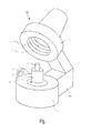
- a dental oven 10 is shown, which is formed in the example as a press furnace.
- the furnace has a combustion hood 12 and a furnace base 14 with a combustion chamber floor 16.
- the firing hood 12 is mounted in a lift-and-pivot manner on the furnace base 14 via a joint 18 which is not shown in detail and only schematically. It is hood-shaped and thus surrounds the combustion chamber 20. At its periphery, it has a combustion chamber heater 22 in a conventional manner.
- the combustion chamber 20 and also the firing cap 12 are configured circular, wherein the combustion chamber has substantially the shape of a hollow cylinder. Accordingly, it is well suited for receiving cylindrical muffles used for pressing dental restoration parts.
- a muffle 26 is in Fig. 1 shown parked on the combustion chamber floor 16.
- the muffle is fitted in a manner known per se with a pressed body or blank 28 whose diameter is in Fig. 1 the clarity is shown enlarged, and is inserted into a guide channel in the muffle 26.
- the pressing of the blank takes place via a press drive, not shown, in the upper part of the firing cap 12.
- the muffle 26 is heated from the outside via the combustion chamber heater 22, so that the desired temperature in their interior, ie in the region of the inserted blank 28, sets only late.
- muffles of different diameters for example, a muffle, which is almost twice the diameter of in Fig. 1 has shown muffle 26.
- the height of the muffle used can also be different, so that the muffle material to be heated can differ from one to the next press cycle by, for example, a factor of four.
- a heat detection device which is designed as a thermal imaging camera 30, attached to the dental oven 10, on the outside of the dental oven, preferably on the furnace base 14th
- the field of view of the thermal imager is directed to an area just above the combustion chamber floor 16, ie to the location at which the muffle 26 - or in the case of a kiln, the dental restoration part - is turned off.
- the thermal imager 30 is set to detect slightly more horizontally and vertically than corresponds to the largest muffle 26 to be used. This is also from the FIG. 2 schematically visible.
- the optical camera can be preceded by an optical system in order to adapt the detection area as required in terms of its size and thus its resolution.
- the thermal imaging camera 30 is protected in a frame 32, which carries no damage even when accidentally abutment of the muffle 26.
- it is preferably not laterally on the side, but laterally attached to the bottom side of the oven 14. As a result, on the one hand it is not in the way, on the other hand it is aligned in the free space, in which typically no other heat sources are arranged.
- the orientation is selected so that the optical axis of the thermal imager 30 coincides with the vertical axis of the combustion chamber 20.
- the muffle In the preheat furnace, the muffle is typically heated to a substantially uniform temperature.
- thermal imaging cameras typically display a color-variant resolution of the temperature, with hot areas yellow, hot areas red, cooler areas green, and cold areas blue. The color spectrum is much more resolved than can be seen here, so that a temperature difference of, for example, 2 ° by the corresponding color variance is apparent.
- the resolution of a thermal imaging camera is orders of magnitude larger than it is from the Figures 2 It can be seen, for example, configurations of 1,000 pixels by 1,500 pixels are readily feasible.
- the contrast between the regions 44 and the region of the muffle 26 makes it readily possible to detect the two-dimensional size of the muffle and to control and regulate the dental oven 10 in accordance with the requirements.
- the time-dependent change of the thermal image 34 which results from the comparison before and after the setting of the muffle, is also important according to the invention.
- Muffles but also dental restoration parts in kilns, each have a predetermined shape. Thus, if hot spots occur in region 44 of the thermal image, they can not originate from the muffle or the dental restoration part and can therefore be easily faded out.
- the thermal imaging camera 30 remains at the predetermined location and thermal imaging is also performed when the firing cap 12 is opened .
- the muffle must - assuming trouble-free operation - be in the same place where it was when the fuel cap was closed, and here, too, the desired temperature profile can be adapted to the requirements or raising the combustion cap 12 and possibly the shutdown of the combustion chamber heating 22 regulate and control.
- thermal imaging camera 30 is shown fixedly mounted as a predetermined location, it is understood that in an alternative embodiment, a pivotable mounting is possible.
- the thermal imaging camera can then be swiveled laterally from the 45 ° position at the rear into the 45 ° position at the front, ie a total of 90 °. This allows especially in furnaces for dental restoration parts the three-dimensional recognition of the dental restoration parts and insofar as it were a stereoscopic thermal imaging.
- the thermal imaging camera 30 according to the invention can thus be used without difficulty for fault detection, but also for identification of the dental objects to be fired.
- FIG. 3 A further embodiment of a thermal imaging camera according to the invention is made Fig. 3 seen.
- a kiln 10 is used, the dental restoration parts 60 receives, which are stored on a burner plate 56, which in turn is placed on the furnace base 14.
- the combustion chamber heater 22 is arranged in the usual manner on the outer circumference of the combustion chamber 20 and radiates partially open when the fuel cap 12 is open.
- the dental restoration parts 60 are heated even when the firing cap 12 is open.
- the thermal imaging camera 30a is aligned with a horizontal viewing axis 62 on the dental restoration parts 60 and detects them laterally.
- thermal imaging camera 30b is aligned in the illustrated embodiment on the burner plate 56, wherein the viewing axis 64 thus just below the dental restoration parts 60 meets this.
- the thermal image of the thermal imaging camera 30b also detects the dental restoration parts 60 due to the oblique orientation of the upper surface thereof. This allows a common and three-dimensional detection of the thermal image or temperature image of the dental restoration parts 60.
- the lower furnace part 14 has a display device 70. This can - controlled by control buttons 72 - also equal to the thermal image of the thermal imaging cameras 30a and 30b show superimposed. In addition, this is evaluated via an image recognition device and made the control of both the closing movement and the supply of heating energy adapted to the requirements.
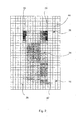
- Fig. 4 shows 3 thermal images that were created at time t0, t1 and t2 of the work area, ie the areas above the surface.
- thresholds for the temperature representation in the image were used. Matrix elements having a lower temperature than the first predetermined threshold become almost black, those with a temperature above that threshold brighter.
- time t0 immediately after setting the firing tray with 3 dental restorations in the kiln almost no temperature differences are visible.
- the objects do not stand out from the background as they have a similar temperature. In the picture shown, however, a high temperature spot can be seen on the top right. Since this is not plausible, the decision can now be made that this is a hot object in the background and therefore these pixels no longer have to be considered for further consideration.
- the set dental objects themselves after they have been set below the hot oven hood, inevitably and continuously heated.
- the heating as such and the rate of heating, and whether it is continuous, can be detected and calculated by corresponding periodic storage of the images in a given time interval considered.
- time t1 as can be seen, some of the firing tray and the objects have already been heated.
- time t2 all objects stand out sharply and sharply from the ground.
- a suitable choice of the mentioned threshold value can be used to detect objects very quickly and accurately in terms of time, so that they would possibly already be possible at time t1.
- the background noise presented at time t0 was either actually removed, or is hidden by the software and no longer included in the image display.
- the firing cap is fixed and the base is movable.
- the firing cap is movably mounted relative to the base.
- the pad can for example be moved vertically, so that the combustion chamber is closed in the uppermost position of the pad and in a lower position of the pad the dental restoration parts can be removed. By the movement of the pad, however, they are automatically shaken, so that this embodiment is not preferred.
- a closed combustion chamber is provided instead of the combustion hood, which is accessible laterally via an oven door.
- a pad in the form of the local furnace bottom is realized, which is intended for the inclusion of one or more dental restoration parts.
- the thermal imager can be attached to the oven door in this solution, or at a fixed position outside the oven door, so that the oven interior is detected. By image analysis, the heating of the dental restoration parts located there can be detected here.
- a window transparent to infrared radiation window in the backward region of the furnace wall is provided.
- the thermal imaging camera is aimed at this window, so that the interior of the combustion chamber is detected, and with the oven door open, the surrounding space.
Abstract
Description
Die Erfindung betrifft einen Dentalofen, gemäß dem Oberbegriff der Ansprüche 1 bzw. 16, sowie ein Verfahren zum Steuern bzw. Regeln eines Dentalofens, gemäß dem Oberbegriff von Anspruch 17.The invention relates to a dental oven, according to the preamble of
Es sind seit längerem Brennöfen für Dentalzwecke bekannt, bei denen Dentalrestaurationsteile über speziell vorgegebene Brenn-, Sinter-, Entbinderungs- und/oder Pressparameter gebrannt, gesintert, entbindert oder verpresst werden. Es ist in diesem Zusammenhang auch bekannt, dass die Qualität der erzeugten Dentalrestaurationsteile stark von der Einhaltung der genannten Prozessparameter über den gesamten Prozess hinweg abhängt.For a long time, kilns for dental purposes have been known in which dental restoration parts are burned, sintered, debindered or pressed by means of specially specified firing, sintering, debindering and / or pressing parameters. It is also known in this connection that the quality of the dental restoration parts produced depends strongly on the compliance of the mentioned process parameters throughout the entire process.
Bei Brennöfen werden Dentalrestaurationsteile typischerweise je einzeln oder gemeinsam auf einem Brennraumboden oder Sockel abgelegt. Zum Brennen wird eine Brennhaube, die die Heizung für den Ofen aufweist, mit dem Brennraumboden zusammengeführt und in der Regel abgedichtet, so dass der Brennzyklus starten kann. Hierbei ist es vorteilhaft, wenn die Brennhaube selbst hub- und/oder schwenkbeweglich gelagert ist, da dann Erschütterungen des Brennraumbodens und damit einhergehende Erschütterungen der Dentalrestaurationsteile sicher vermieden werden können.In kilns, dental restoration parts are typically deposited individually or collectively on a combustion chamber floor or pedestal. For firing a firing cap, which has the heater for the furnace, merged with the combustion chamber floor and sealed in the rule, so that the firing cycle can start. It is advantageous if the combustion hood itself is mounted in a lifting and / or pivoting manner, since then vibrations of the combustion chamber floor and concomitant vibrations of the dental restoration parts can be safely avoided.
Sobald die Brennhaube geschlossen ist, kann mit dem eigentlichen Brenn-, Sinter-, Entbinderungs- oder Pressprozess begonnen werden, wobei typischerweise sicherheitshalber eine Haltezeit eingeschoben wird.Once the fuel cap is closed, you can start with the actual burning, sintering, debinding or pressing process, typically a safety time is a holding time is inserted.
Nachdem sowohl bei Brennöfen, Sinteröfen, Entbinderungsöfenals auch bei Pressöfen die verwendeten Materialien empfindlich auf eine Nicht-Einhaltung von Prozessparameter, insbesondere Temperatur und Druck, reagieren, werden üblicherweise mehrere Sensoren, insbesondere Drucksensoren und/oder Temperatursensoren eingesetzt, um den genauen Verlauf der Prozessparameter zu erfassen und gegebenenfalls regelnd einzugreifen.Since the materials used react sensitively to non-compliance with process parameters, in particular temperature and pressure, in the case of furnaces, sintering furnaces, debinding furnaces as well as press furnaces, it is customary to use a plurality of sensors, in particular pressure sensors and / or temperature sensors, in order to determine the exact course of the process parameters and, if necessary, intervene in a regulatory manner.
Grundsätzlich kann insbesondere ein Brenn-, Entbinderungs- und oder Sinterprozess in mehrere Unterabschnitte aufgeteilt werden, so. z.B. in einen Trocknungsprozess, bzw.-Entbinderungsprozess, gefolgt vom eigentlichen Brenn- bzw. Sinterprozess, wiederum gefolgt von einem Abkühlprozess.In principle, in particular a combustion, debindering and or sintering process can be divided into several subsections, so. e.g. in a drying process or debinding process, followed by the actual firing or sintering process, again followed by a cooling process.
Trocknungsprozesse werden meist bei einem noch vollständig bzw. teilweise geöffnetem Brennofen durchgeführt, analoges gilt für Abkühlprozesse.Drying processes are usually carried out in a still fully or partially open kiln, the same applies to cooling processes.
Dies ist insbesondere von Bedeutung bei der Verarbeitung von, durch die Herstellung bedingt noch feuchten Dentalkeramiken (z.B. Schichtkeramiken, Glasieren, Glaslot, etc.) oder Keramiken, bei welchen Aufheizgradienten zur Vermeidung von Schäden z.B. durch Risse, Blasen, Porositäten, unvollständige Verdampfung oder Verbrennung von organischen Materialien und/oder Aufheiz- und Abkühlgradienten zur Begrenzung von Spannungen in der Keramik selbst, oder durch unterschiedliche Temperaturgradienten zwischen unterschiedlichen Gerüstwerkstoffen (Metall oder Keramik) und den aufgebrachten Schichtwerkstoffen oder Verblendungen wichtig sind.This is particularly important in the processing of dental ceramics which are conditionally still wet by the manufacture (e.g., layered ceramics, glazing, glass solder, etc.) or ceramics in which heating gradients are used to prevent damage, e.g. by cracks, bubbles, porosities, incomplete evaporation or combustion of organic materials and / or heating and cooling gradients for limiting stresses in the ceramic itself, or by different temperature gradients between different framework materials (metal or ceramic) and the applied coating materials or veneers are important ,
Standardmässig arbeiten heutige Geräte mit empirisch ermittelten Einstellungen. Das Schließen oder Öffnen der Brennhaube erfolgt in einem vorgegebenen Prozess z.B. in einer vorgegebenen Zeit und mit einer vorgegebenen Schliessbewegung z.B. linear oder über fest vorgegebene Positionen. Dabei kann die Brennhaube bereits auf eine vordefinierte Temperatur beheizt werden oder frei abkühlen.By default, today's devices work with empirically determined settings. The closing or opening of the firing cap takes place in a predetermined process, e.g. in a given time and with a given closing movement e.g. linear or fixed positions. The combustion hood can already be heated to a predefined temperature or allowed to cool freely.
Es ist bereits vorgeschlagen worden, empirisch erarbeitete Modelle zu verwenden, gemäß welchen beispielsweise auf Basis der im Ofenkopf gemessenen Temperatur die Wärmeenergie und die zu erwartende Erwärmung als Funktion des Abstandes der heissen Brennhaube zu dentalen Objekt hin geschätzt werden und die Schliessbewegung auf Basis von experimentell ermittelten Modellen angepasst wird.It has already been proposed to use empirically developed models, according to which, for example, based on the temperature measured in the furnace head, the heat energy and the expected heating as a function of the distance of the hot combustion hood to the dental object are estimated and the closing movement on the basis of experimentally determined Models is adjusted.
Ferner ist es vorgeschlagen worden, Thermoelemente zu verwenden, die sich im Ofenkopf oder Brennsockel, und zwar in der Nähe des Arbeitsbereiches von zu verarbeitenden dentalen Restaurationen befinden, dennoch aber die Temperatur dieser Objekte nicht exakt wiedergeben können. Es ist schwierig, diese Sensoren entsprechend den Gegebenheiten auszurichten. Ein Thermoelement müsste an einem dentalen Objekt angebracht werden, was in der Praxis nicht durchführbar ist.Furthermore, it has been proposed to use thermocouples which are located in the furnace head or firing base, in the vicinity of the working area of dental restorations to be processed, but nevertheless can not accurately reproduce the temperature of these objects. It is difficult to align these sensors according to the circumstances. A thermocouple would have to be attached to a dental object, which is not feasible in practice.
Schließlich ist es auch vorgeschlagen worden, ein optisches Temperaturinstrument auf das Objekt z.B. unter Zuhilfenahme eines Lichtstrahles (Laserpointer) auszurichten, um einen repräsentativen Messwert für die Temperatur des Objektes zu erhalten.Finally, it has also been proposed to align an optical temperature instrument on the object, for example with the aid of a light beam (laser pointer), in order to obtain a representative measured value for the temperature of the object.
Nachteilig ist bei diesen beschriebenen Varianten, dass eine fehlerhafte Anbringung von Sensor und/oder Dentalobjekt zu einem grossen Messfehler führen kann. Zudem ist die Anbringung der Sensoren teilweise schwierig, z. B. wenn das Objekt eine pulverförmige Konsistenz besitzt. Zudem erschließt sich die Messposition der Sensoren dem Anwender/Bediener, d.h. in der Regel dem Zahntechniker, nicht, was in besonderen Maße gilt, wenn mehrere dentale Restaurationen und/oder grössere dentale Restaurationen zu verarbeiten sind.A disadvantage of these described variants that a faulty attachment of sensor and / or dental object can lead to a large measurement error. In addition, the attachment of the sensors is sometimes difficult, z. B. if the object has a powdery consistency. In addition, the measurement position of the sensors is revealed to the user / operator, i. usually the dental technician, not, which is particularly true when multiple dental restorations and / or larger dental restorations are to be processed.
Im Hinblick auf die bestehenden Probleme und auch auf die Haftungsrisiken durch fehlerhaft gebrannte Dentalrestaurationsteile wird in der Regel mit erheblichen Sicherheitsreserven gebrannt, also mit verlängerten Haltezeiten, während derer das Temperaturniveau sich angleichen soll. Die Festlegung von verlängerten Haltezeiten wird dabei teilweise dem Anwender überlassen. Hierbei wird jedoch eine Verschlechterung der Eigenschaften der für das Brennen das Dentalrestaurationsteils verwendeten Keramik in Kauf genommen.In view of the existing problems and also on the liability risks caused by incorrectly fired dental restoration parts is usually burned with considerable safety reserves, ie with extended holding times, during which the temperature level is to be equalized. The determination of extended holding times is partly left to the user. In this case, however, a deterioration of the properties of the ceramic used for firing the dental restoration part is accepted.
Demgegenüber liegt der Erfindung die Aufgabe zugrunde, einen Dentalofen gemäß dem Oberbegriff von Anspruch 1 bzw. 16 sowie ein Verfahren gemäß dem Oberbegriff von Anspruch 17 zu schaffen, die eine verbesserte Qualität der herzustellenden Dentalrestaurationsteile erlauben.In contrast, the invention has for its object to provide a dental oven according to the preamble of
Diese Aufgabe wird erfindungsgemäß durch die Ansprüche 1, 16 bzw. 17 gelöst. Vorteilhafte Weiterbildungen ergeben sich aus den Unteransprüchen.This object is achieved by the
Erfindungsgemäß ist bei einem Dentalofen eine Wärmeerfassungsvorrichtung, die als Wärmebildkamera ausgebildet ist, auf den Bereich oberhalb des Brennraumbodens oder der Unterlage gerichtet, auf der das Dentalrestaurationsteil angeordnet ist. Die Wärmebildkamera ist damit auf den Arbeitsbereich, in welchem Dentalrestaurationsteile positioniert werden können, gerichtet, vorzugsweise von seitlich außerhalb des Dentalofens, und vermag dessen Wärmestrahlung zweidimensional zu erfassen.According to the invention, in a dental oven, a heat detection device, which is designed as a thermal imaging camera, directed to the area above the combustion chamber floor or the base on which the dental restoration part is arranged. The thermal imaging camera is thus directed to the work area in which dental restoration parts can be positioned, preferably from the side outside the dental oven, and is capable of detecting its thermal radiation two-dimensionally.
Die zweidimensionale Aufnahme durch die Wärmebildkamera ermöglicht die Erfassung einer Wärmematrix, also einer Matrix aus Punkten, die je eine Temperatur an einer vorgegebenen Stelle wiedergeben. Bei entsprechender Auflösung können auch noch kleinstmögliche dentale Objekte noch sicher erfasst und deren Temperatur gemessen werden.The two-dimensional recording by the thermal imaging camera allows the detection of a heat matrix, ie a matrix of points, each of which reflects a temperature at a predetermined location. With appropriate resolution, even the smallest possible dental objects can still be safely detected and their temperature can be measured.
Dies bietet eine Vielzahl von Vorteilen:
- Während mit einem einfachen Temperatursensor in der Regel nur eine punktförmige Temperaturerfassung möglich ist, ermöglicht die zweidimensionale Temperaturerfassung auch gleich die Erfassung der Temperaturverteilung. Dies ermöglicht auch eine Erkennung der Form, der Grösse, der Position, der Anzahl eventuell sogar der Art der zu verarbeitenden Dentalrestaurationsteile.
- While with a simple temperature sensor usually only a punctiform temperature detection is possible, the two-dimensional temperature detection also allows equal to the detection of the temperature distribution. This also allows recognition of the shape, the size, the position, the number possibly even the type of dental restoration parts to be processed.
Erfindungsgemäß ist es günstig, dass die Temperatur an einem oder mehrehren dentalen Objekten unabhängig von deren Form, Grösse, Masse, Anzahl und Materialisierung an einer oder mehreren Positionen im Arbeitsbereich, d.h. dem Brennraum des Ofens an einer repräsentativen oder aber für den Prozess relevanten Position gemessen werden kann.In accordance with the invention, it is convenient that the temperature at one or more dental objects be independent of their shape, size, mass, number and materialization at one or more positions in the working area, i. the combustion chamber of the furnace at a representative or for the process relevant position can be measured.
Erfindungsgemäß können innerhalb der gesamten Temperaturmatrix die relevante Information, z. B. die dentalen Restaurationsteile erfasst und erkannt werden und von nicht relevanten Informationen, z.B. Störungen im Hintergrund, oder von Bauteilen des Dentalofens unterschieden werden.According to the invention, within the entire temperature matrix, the relevant information, for. For example, the dental restoration parts are detected and recognized, and of non-relevant information, e.g. Disturbances in the background, or to be distinguished from components of the dental oven.
Bevor die Dentalrestaurationsteile eingesetzt sind, ist die Wärmebildkamera bei einem Ofen mit geöffneter Haube auf die Umgebung gerichtet, die typischerweise auf Umgebungstemperatur ist. Wenn die Dentalrestaurationsteile - üblicherweise platziert auf einem Brenngutträger, welcher das Einstellen bzw. die Entnahme erleichtert -, auf den Ofenboden aufgesetzt werden, kann zum einen erkannt werden, dass der heisse Ofensockel nun abgedeckt wurde. Damit kann das Einstellen eines Brenngut-Trägers erkannt werden. Bei der Entnahme eines Trägers würde dies wiederum erkannt werden, weil der Brennsockel gegenüber dem Träger eine Temperaturdifferenz besitzt. Die beim Einstellen noch nicht erwärmten Dentalrestaurationsteilen, welche in etwa die Temperatur der Umgebung bzw. des Brenngutträgers, auf welchem Sie platziert sind, haben, führen in den ersten Sekunden noch zu keiner Bildänderung. Erst wenn die über den Dentalrestaurationsteilen sich erstreckende heiße Ofenhaube und der Brennsockel, auf welchem der Brenngutträger mit den Objekten steht, die Dentalrestaurationsteile etwas erwärmt, zeichnet sich deren Kontur gegenüber dem Hintergrund als Wärmematrix ab.Before the dental restoration parts are used, the thermal imaging camera in an open hooded oven is aimed at the environment, which is typically at ambient temperature. If the dental restoration parts - usually placed on a firing tray, which facilitates the setting or removal - placed on the bottom of the furnace, it can be seen on the one hand that the hot furnace base has now been covered. Thus, the setting of a kiln carrier can be detected. Upon removal of a carrier, this would in turn be detected because the fuel header has a temperature difference with respect to the carrier. The not yet heated in setting Dentalrestaurationsteilen, which have approximately the temperature of the environment or the firing tray on which they are placed, lead in the first few seconds nor to any image change. Only when the hot oven hood extending over the dental restoration parts and the firing base on which the firing tray stands with the objects slightly heats the dental restoration parts do their contour vis-à-vis the background become apparent as a heat matrix.
Dadurch lassen sich während des Aufheizvorgangs, gerade in die vorgewärmte Brennkammer eingebrachte und sich auf niedriger Temperatur (meist in der Nähe der Umgebungstemperatur) befindende Dentalrestaurationsteile, beispielsweise während des Trocknungsprozesse, identifizieren und dann die relevante Temperatur dieser oder auch die Temperaturverteilung dieser Objekte ermitteln und überwachen.In this way, during the heating process, dental restoration parts introduced directly into the preheated combustion chamber and located at a low temperature (usually in the vicinity of the ambient temperature), for example during the drying process, can be identified and the relevant temperature or temperature distribution of these objects can be determined and monitored ,
Erfindungsgemäß besonders günstig ist es, dass die so gewonnenen Ergebnisse und Erkenntnisse ohne jeglichen Zusatzaufwand und ohne weiteres für die Steuerung bzw. die Regelung des Ofens verwendet werden können. Bei bekanntem und ortsfestem Abstand der Wärmebildkamera vom Brennraumboden bzw. Arbeitsbereich lässt sich aus der Größe der Wärmematrix ohne weiteres auch die Größe der eingestellten Objekte abschätzen und trigonometrisch berechnen.According to the invention, it is particularly favorable that the results and findings obtained in this way can be used without any additional expenditure and without further ado for the control or regulation of the furnace. With known and fixed distance of the thermal imaging camera from the combustion chamber floor or work area can be from the size the heat matrix also readily estimate the size of the set objects and calculate trigonometrically.
Damit lassen sich dann gewünschte Prozessparameter, welche größenabhängig sein können, ebenfalls und automatisch in der gewünschten Weise einstellen. So z.B. kann bei Feststellen von grossen Dentalrestaurationsteilen oder mehreren Dentalrestaurationsteilen die Aufheizrate, d.h. der gewünschte Temperaturanstieg, an dem Objekt reduziert werden, um eine schonende und sichere Trocknung zu erreichen.In this way, desired process parameters, which can be size-dependent, can also be adjusted automatically in the desired manner. For example, For example, when determining large dental restoration parts or multiple dental restoration parts, the heating rate, i. the desired increase in temperature at which the object is reduced in order to achieve a gentle and safe drying.
Auch bei mehreren Objekten kann aufgrund vorgegebener Methoden der Prozess sicher gestaltet werden. So kann beispielsweise auf das Temperaturmaximum geregelt werden, um Poren und Risse bei einer Trocknung zu verhindern. In anderen Fällen kann z.B. eine Mittelwertbildung der identifizierten und relevanten Temperaturmesspunkte von Vorteil sein. In weiterer Ausgestaltung ist es vorgesehen, dass an allen identifizierten Messpunkten eine Mindesttemperatur erreicht sein muss, bevor sich ein Folgeprozess anschliesst.Even with multiple objects, the process can be designed safely based on predefined methods. For example, the temperature maximum can be regulated to prevent pores and cracks during drying. In other cases, e.g. an averaging of the identified and relevant temperature measurement points would be advantageous. In a further embodiment, it is provided that a minimum temperature must be reached at all identified measuring points before a subsequent process follows.
Grundsätzlich wäre es auch möglich, bei entsprechender Ausrichtung der Wärmebildkamera weitere Informationen, wie Art des verwendeten Trägers, auf welchem die Dentalrestaurationsteile im Brennofen positioniert sind, zu erfassen, ebenso wie auch dessen Grösse und/oder dessen Temperatur. Diese Informationen können im aktuellen Prozessschritt, aber auch in einem nachfolgenden Prozessschritt, z.B. dem Brennprozess, erfindungsgemäß verwendet werden. So lassen sich die Fehler durch unterschiedliche Grössen und Massen von Brennträgern ausschalten und die zu erreichende Endtemperatur der Dentalrestaurationsteile während des Brennprozesses bleibt unabhängig von diesen.In principle, it would also be possible to detect further information, such as the type of carrier used, on which the dental restoration parts are positioned in the kiln, with appropriate orientation of the thermal imaging camera, as well as its size and / or its temperature. This information can be in the current process step, but also in a subsequent process step, e.g. the firing process, are used according to the invention. Thus, the errors can be switched off by different sizes and masses of burners and reach the final temperature of the dental restoration parts during the firing process is independent of these.
Die Identifikation eines Brenngutträgers kann erfindungsgemäß in analoger Weise wie bei den Dentalrestaurationsteilen erfolgen.The identification of a Brenngutträgers can be carried out according to the invention in an analogous manner as in the dental restoration parts.
Zugleich erlaubt die erfindungsgemäße Wärmebildkamera eine Regelung der Vorwärmung und/oder der Kühlung auf Basis der an den Objekten erfassten Temperatur, durch Verändern der Position des Ofenkopfes gegenüber dem Ofenboden oder der Veränderung der Ofentemperatur im Ofenkopf durch Heizen oder Kühlen oder gleichzeitiger Veränderung der Position und der Heizleistung. Auch die Temperatur selbst und die Temperaturverteilung im von der Wärmebildkamera erfassten Bereich lassen sich erfassen.At the same time, the thermal imaging camera according to the invention allows a control of the preheating and / or cooling on the basis of the detected temperature on the objects, by changing the position of the furnace head relative to the furnace bottom or the change of the furnace temperature in the furnace head by heating or cooling or simultaneous change of position and Heating capacity. The temperature itself and the temperature distribution in the area covered by the thermal imager can also be recorded.
Es versteht sich, dass in gleicher Weise natürlich auch die Stellung der Ofenhaube relativ zu den Dentalrestaurationsteilen geregelt werden kann. So kann auch die Absenkung der Ofenhaube gesteuert und geregelt werden, um die Temperatur bzw. den Temperaturanstieg an den zuvor identifizierten Dentalrestaurationsteilen einem vorgegebenen Sollverlauf folgen zu lassen.It is understood that in the same way, of course, the position of the furnace hood can be regulated relative to the dental restoration parts. Thus, the lowering of the furnace hood can be controlled and regulated to the temperature or the temperature rise to follow a predefined set course at the previously identified dental restoration parts.
Erfindungsgemäß besonders günstig ist es, dass aufgrund des Temperaturverlaufs festgestellt wird, ob eventuelle für die Verarbeitung und Herstellung notwendige Liquids (z.B. Restwasser) verdunstet sind und dann, gegebenenfalls nach Einschieben einer gewissen Haltezeit, das Absenken der Haube bzw. die Temperaturerhöhung weiter und automatisch fortgesetzt werden kann.It is particularly favorable according to the invention that it is ascertained on the basis of the temperature profile whether any liquids (eg residual water) necessary for processing and production have evaporated and then, if appropriate after insertion of a certain holding time, the lowering of the hood or the temperature increase continues and continues automatically can be.
Ebenso kann erfindungsgemäß durch die Wärmebildkamera mit der Steuer- und Regelvorrichtung sichergestellt werden, dass unabhängig von Art, Anzahl und Masse der Dentalrestaurationsteile eine vorgegebene Temperatur oder Temperaturverteilung sicher erreicht wurde. Dies ermöglicht eine auf die Erfordernisse der Keramiken zugeschnittene Prozessdauer, und zwar ohne die bereits eingangs erwähnten Sicherheitsreserven, aber auch, ohne Risiken einzugehen.Likewise, according to the invention can be ensured by the thermal imaging camera with the control and regulating device that regardless of the type, number and mass of dental restoration parts a predetermined temperature or temperature distribution has been achieved safely. This allows a tailored to the requirements of the ceramics process duration, without the safety reserves already mentioned above, but also without taking risks.
Durch den zwangsläufig auftretenden Temperaturunterschied zwischen dem Hintergrund und den Dentalrestaurationsteilen lässt sich der Hintergrund gleichsam elektronisch ausblenden: über einen entsprechenden Filter bzw. Bilddatenverarbeitungsroutinen wird kurzerhand die Erfassung auf diejenigen Matrixzellen beschränkt, deren Temperatur die Raumtemperatur übersteigt.Due to the inevitably occurring temperature difference between the background and the dental restoration parts, the background can be hidden electronically as it were: via a corresponding filter or image data processing routines, the detection is limited to those matrix cells whose temperature exceeds the room temperature.
Im Betrieb eines Brennofens wird der Zahnersatz, die Krone oder die Brücke oder eine entsprechende Mehrfachanordnung bei geöffneter Ofenhaube, aber eingeschalteter Ofenheizung auf dem Brennraumboden abgelegt. Auch wenn die Ofenheizung von dem Dentalrestaurationsteil dann noch ein gutes Stück beabstandet ist, erfolgt eine Wärmeübertragung, die dazu führt, dass sich die Dentalrestaurationsteile langsam erwärmen. Bereits in diesem Zustand lässt die Wärmebildkamera, die auf den Bereich knapp oberhalb des Brennraumbodens gerichtet ist, erkennen, dass dort Dentalrestaurationsteile liegen, aber auch deren Form in der zweidimensionalen Projektion betrachtet.During operation of a kiln, the dental prosthesis, the crown or the bridge or a corresponding multiple arrangement is deposited on the combustion chamber floor with the furnace hood open, but with the furnace heating switched on. Even if the oven heating of the dental restoration part then still a good distance away, there is a heat transfer, which causes the dental restoration parts heat slowly. Already in this state, the thermal imaging camera, which is directed to the area just above the combustion chamber floor, detects that there are dental restoration parts, but also looks at their shape in the two-dimensional projection.
Aus dem Verlauf der Erwärmung lässt sich dann auch in gewissem Maße auf die Masse der Dentalrestaurationsteile schließen.From the course of the heating can then be concluded to some extent on the mass of the dental restoration parts.
Es versteht sich, dass dieses Prozedere in gleicher Weise anwendbar ist, wenn der Brennofen bei noch ausgeschalteter Heizung aufgrund des vorherigen Brennzyklus noch warm ist. In diesem Fall gibt typischerweise sowohl der Brennraumboden als auch die - geöffnete - Haube Wärme an die Dentalrestaurationsteile ab, die sich hierdurch wärmebildmäßig von dem auf Raumtemperatur befindlichen Hintergrund abheben.It should be understood that this procedure is equally applicable if the kiln is still warm with the heater still off because of the previous firing cycle. In this case, typically, both the combustion chamber bottom and the - opened - hood heat to the dental restoration parts, which thereby stand out in terms of heat image of the background on room temperature background.
In gleicher Weise lässt sich die Wärmebilderkennung im Falle eines Pressofens unter Verwendung einer Muffel durchführen. Typischerweise wird eine Muffel mit eingesetztem Rohling in einem Vorwärmofen erwärmt, typischerweise auf 850 °C. Wiederum kann der eigentliche Pressofen dann von dem vorherigen Presszyklus noch warm sein. Bei geöffneter Ofenhaube wird die heisse Muffel in an sich bekannter Weise auf den Brennraumboden aufgesetzt. Die heisse Muffel führt auch hier zu einer Veränderung der Temperatur an Matrixelementen, die zuvor Umgebungstemperaturen, bzw. Temperaturen des Hintergrundes erfasst haben. Dies ermöglicht auch hier, durch Auswertung der zeitlichen Veränderung der einzelnen Wärmebilder das Einsetzen der Muffel zu erkennen.In the same way, the thermal image recognition can be performed in the case of a press furnace using a muffle. Typically, a blank-inserted muffle is heated in a preheat oven, typically 850 ° C. Again, the actual press furnace can then still be warm from the previous press cycle. When the oven hood is open, the hot muffle is placed in a conventional manner on the combustion chamber floor. Here, too, the hot muffle leads to a change in the temperature of matrix elements which have previously detected ambient temperatures or temperatures of the background. This also makes it possible to detect the onset of the muffle by evaluating the temporal change of the individual thermal images.
Die so gewonnenen Informationen lassen sich in ausgesprochen einfacher Weise für die Steuerung des Ofens während des Schließvorgangs der Brennhaube verwenden, wobei es sich versteht, dass auch Sicherheitsüberwachungen oder das Auslösen von Alarmen ohne weiteres darstellbar sind.The information thus obtained can be used in a very simple manner for the control of the furnace during the closing of the combustion hood, it being understood that safety monitoring or the triggering of alarms are readily representable.
Lediglich als Beispiel hierfür sei die Konstellation beschrieben, wenn eine Muffel außermittig im Brennraum platziert ist. Die Wärmebildkamera kann sofort erfassen, wenn die warme Matrix seitlich versetzt ist und dann einen Alarm abgeben bzw. den Benutzer zur Korrektur auffordern. Auch wenn der Versatz nicht seitlich, sondern in Wärmestrahlungsrichtung erfolgt, ist dies aber erfassbar: Dies dadurch, dass eine ortsfest gegenüber der Aufstellposition der Pressmuffel montierte Kamera gleichzeitig die geometrische Grösse des Objektes bestimmen kann. Befindet sich das Objekt aussermittig und zu nahe an die Kamera erscheint es grösser im Bild, ist es weiter weg, erscheint es kleiner.Only as an example of this, the constellation is described when a muffle is placed off-center in the combustion chamber. The thermal imaging camera can detect immediately if the warm matrix is offset laterally and then give an alarm or prompt the user for correction. Even if the offset does not take place laterally, but rather in the direction of heat radiation, this is detectable: This is due to the fact that a camera mounted in a fixed position relative to the installation position of the press muffle can simultaneously determine the geometrical size of the object. If the object is off-center and too close to the camera, it will appear larger in the image; if it is further away, it will appear smaller.
Die Steuerung bzw. die Regelung des Brennofens oder des Pressofens erfolgt erfindungsgemäß automatisch größenabhängig, temperaturabhängig und zeitabhängig; wobei sowohl die Größe des Dentalrestaurationsteils bzw. der Muffel als auch deren Temperatur erfindungsgemäß von der Wärmebildkamera erfasst werden.The control or regulation of the kiln or the press furnace is carried out according to the invention automatically size-dependent, temperature-dependent and time-dependent; wherein both the size of the dental restoration part or the muffle and its temperature are inventively detected by the thermal imaging camera.
In erfindungsgemäß besonders günstiger Ausgestaltung ist es vorgesehen, das Wärmebild auch - gegebenenfalls elektronisch aufbereitet - auf einem Bildschirm des Ofens oder einem Bildschirm, der mit dem Ofen in Verbindung steht, darzustellen. Hierdurch lässt sich eine auch visuelle Plausibilitätskontrolle realisieren. In einer weiteren Ausprägung ist es vorgesehen, dass der Zahntechniker dieses Bild bearbeitet und gegebenenfalls sogar interaktiv eingreift, z.B. um die von der Wärmebildkamera festgelegte Vorauswahl der Objekte abzuändern, oder den Messpunkt für die Prozessführung manuell festzulegen oder zu verschieben.In a particularly advantageous embodiment according to the invention, it is provided that the thermal image also - possibly electronically processed - on a screen of the furnace or a screen that communicates with the furnace, represent. This allows a visual plausibility check to be realized. In a further embodiment, it is provided that the dental technician processes this image and possibly even intervenes interactively, e.g. to change the pre-selection of objects defined by the thermal imager or to manually set or move the process control point.
Typischerweise ist die Wärmebildkamera so ausgerichtet, dass sie schräg hinten an dem Ofen angebracht ist und diesen insbesondere schräg nach vorne erfasst. An der dem Brennraum oben von der Wärmebildkamera aus gesehen gegenüberliegenden Seite sind typischerweise keine Wärmequellen, die die Erfassung durch die Wärmebildkamera beeinträchtigen könnten. Dennoch vorhandene Wärmequellen, wie beispielsweise ein zufälligerweise in Blickrichtung der Kamera stehender, geöffneter und dementsprechend heißer Brennofen kann dennoch vom Dentalrestaurationsteil unterschieden werden. Dies deshalb eine fremde Wärmequelle einen anderen zeitlichen Temperaturverlauf hat als in den erfindungsgemäßen Dentalofen eingestellte Dentalrestaurationsteile. Die genannte Position der Kamera ist auch günstig, weil es dadurch dem Anwender erschwert wird, versehentlich störende Objekte zwischen Kamera und den zu erfassenden Dentalrestaurationsteilen einzubringen.Typically, the thermal imaging camera is oriented so that it is mounted obliquely at the back of the oven and this particular obliquely detected forward. At the Combustion chambers seen from the top of the thermal imaging camera are typically not heat sources that could interfere with thermal imager detection. Nevertheless, existing heat sources, such as an accidentally standing in the direction of the camera, open and therefore hot kiln can still be distinguished from the dental restoration part. This is why a foreign heat source has a different temporal temperature profile than set in the dental furnace according to the invention Dentalrestaurationsteile. The said position of the camera is also favorable because it makes it more difficult for the user to introduce inadvertently interfering objects between the camera and the dental restoration parts to be detected.
In diesem Zusammenhang sind natürlich auch Plausibilitätsprüfungen realisierbar, die beispielsweise große Temperaturen zu Beginn der Wärmebehandlung als nicht plausibel eliminieren. Auch kann beispielsweise über eine Handbewegung zwischen dem Hintergrund der Wärmebildkamera und dem Ofen die Hintergrundunterscheidung erleichtert werden, da die entsprechenden Temperaturgradienten bei nacheinander aufgenommenen Wärmebildern in vom dentalen Objekt nicht abgedeckten Matrixelementen erkennbar sind.In this context, of course, plausibility checks are feasible, for example, eliminate large temperatures at the beginning of the heat treatment as not plausible. It is also possible, for example, to facilitate the background differentiation by means of a hand movement between the background of the thermal imaging camera and the oven, since the corresponding temperature gradients can be recognized in successively recorded thermal images in matrix elements not covered by the dental object.
Erfindungsgemäß lässt sich sowohl die absolute Temperatur des Brennguts als auch die Entwicklung bzw. die Veränderung der Temperatur an dem je betrachteten Matrixelement erfassen und auswerten.According to the invention, both the absolute temperature of the combustible material as well as the development or the change in the temperature of the respectively considered matrix element can be detected and evaluated.
Auch ist eine Überwachung über den eigentlichen Aufwärmvorgang hinaus möglich. Typischerweise darf sich das Brennobjekt während des Prozesses hinsichtlich seiner Position nicht verändern. Auch diese Tatsache lässt sich mit der erfindungsgemäßen Wärmebildkamera für die Fehlerüberwachung einsetzen.It is also possible to monitor beyond the actual warm-up process. Typically, the focal object must not change position during the process. This fact can also be used with the thermal imaging camera according to the invention for error monitoring.
Während in günstiger Weise die Achsausrichtung der Wärmebildkamera exakt horizontal ist und die vertikale Mittenachse des Brennofens bzw. Pressofens schneidet, ist es in erfindungsgemäß modifizierter Ausgestaltung auch möglich, die Wärmebildkameraachse zu neigen, beispielsweise um bis zu 15° nach oben oder unten, um gegebenenfalls eine noch bessere Unterscheidbarkeit oder eine verbesserte Erfassung der Dentalrestaurationsteile zu realisieren.While favorably, the axis alignment of the thermal imager is exactly horizontal and intersects the vertical center axis of the kiln or press furnace, it is also possible in accordance with the invention modified embodiment, the thermal imaging camera axis to tilt, for example, up to 15 ° up or down to possibly one to realize even better distinctness or improved detection of the dental restoration parts.
In einer weiter modifizierten Ausgestaltung ist die Wärmebildkamera für einen Brennofen entlang eines Kreissegments von beispielweise 90° verschwenkbar. Durch die unterschiedlichen Positionen lassen sich damit dreidimensionale Wärmebilder der sich erwärmenden Dentalrestaurationsteile anfertigen und entsprechend auswerten.In a further modified embodiment, the thermal imaging camera for a kiln can be pivoted along a circular segment of, for example, 90 °. Due to the different positions, three-dimensional thermal images of the heating dental restoration parts can thus be prepared and evaluated accordingly.
Gegebenenfalls kann die erfindungsgemäße Wärmebildkamera auch bei abgesenkter Ofenhaube arbeiten. Hierzu ist ein hinsichtlich Infrarotstrahlung durchlässiges Sichtfenster, in der Brennhaube vorgesehen, as einen möglichst langen Sichtkontakt mit den zu messenden Objekten auch bei sich absenkender Brennhaube erlaubt.Optionally, the thermal imaging camera according to the invention can also work with the furnace hood lowered. For this purpose, a viewing window permeable to infrared radiation, provided in the firing hood, permits the longest possible visual contact with the objects to be measured even when the firing hood is lowered.
In einer weiteren Ausgestaltung ist die Kamera an der Brennhaube angebracht, wobei sich dann die ortsbezogenen Daten mit der Position der Ofenhaube ändern. Dies kann aber bei Anbringung einer Positionserfassungseinrichtung für die Brennhaube entsprechend berücksichtigt werden, und kann auch laufend für die Steuerung und Regelung des Prozesses berücksichtigt werden.In a further embodiment, the camera is attached to the combustion hood, wherein then change the location-related data with the position of the furnace hood. However, this can be taken into account accordingly when attaching a position detection device for the combustion hood, and can also be considered continuously for the control and regulation of the process.
Besonders günstig ist es, wenn die Steuervorrichtung die einzelnen Matrixelemente der Matrix sowohl hinsichtlich der erfassten Temperatur als auch hinsichtlich der Anordnung, also, an welchen Stellen warme Bereiche sind und an welchen nicht, auswertet, und für eine Prozessführung als relevant oder nicht relevant identifiziert. Hierzu kann sie zum Beispiel einen warmen Bereich, der eine hochrechteckige Form aufweist, als warme Muffel identifizieren.It is particularly favorable if the control device evaluates the individual matrix elements of the matrix both with regard to the detected temperature and with regard to the arrangement, ie at which points warm areas are and which are not, and identified as relevant or irrelevant for a process control. For this purpose, for example, it can identify a warm area that has a high-rectangular shape as a warm muffle.
In vorteilhafter Ausgestaltung ist es vorgesehen, dass die als relevant identifizierten Matrixelemente auf beliebige mathematische Weise wie z. B. über die Bildung eines Mittelwerts, eines Maximalwerts, eines Mittelwerts von Maximalwerten einzelner indentifizierter Restaurationen, beispielsweise auch unter Berücksichtigung der Anzahl der Matrixelemente und damit der Grösse bzw. Anzahl der Objekte, zu einem Vorgabewert für die Regelung verrechnet werden.In an advantageous embodiment, it is provided that the identified as relevant matrix elements in any mathematical way such. B. on the formation of an average value, a maximum value, an average value of maximum individual indentifizierter restorations, for example, taking into account the number of matrix elements and thus the size or number of objects, are charged to a default value for the scheme.
In vorteilhafter Ausgestaltung ist es vorgeshen, dass die Steuervorrichtung die einzelnen Matrixelemente der Matrix sowohl hinsichtlich der erfassten Temperatur als auch hinsichtlich der Anordnung, also, an welchen Stellen warme Bereiche sind und an welchen nicht, auswertet, und für eine Prozessführung als relevant oder nicht relevant identifiziert.In an advantageous embodiment, it is provided that the control device evaluates the individual matrix elements of the matrix both with regard to the detected temperature and with regard to the arrangement, that is, at which locations warm areas and at which not, and for a process management as relevant or not relevant identified.
In vorteilhafter Ausgestaltung ist es weiter vorgesehen, dass die Steuer- oder Regelvorrichtung das Wärmebild des erfassten Objekts, insbesondere des erfassten Dentalrestaurationsteils, hinsichtlich seiner relativen Lage bezogen auf die Unterlage und/oder die Brennhaube und damit den Dentalofen erfasst und auswertet.In an advantageous embodiment, it is further provided that the control or regulating device detects and evaluates the thermal image of the detected object, in particular the detected dental restoration part, with respect to its relative position relative to the base and / or the firing hood and thus the dental oven.
In vorteilhafter Ausgestaltung ist es vorgesehen, dass die Steuer- oder Regelvorrichtung das Wärmebild, hinsichtlich seiner zeitlichen Entwicklung (1. Ableitung) erfasst und auswertet und aus der ortsbezogenen Veränderung der Temperatur die dentalen Restaurationen bzw. die für die Prozessführung relevanten Matrixelemente identifiziert und den Dentalofenin Abhängigkeit von diesen Matrixelementen steuert.In an advantageous embodiment, it is provided that the control or regulating device detects and evaluates the thermal image with regard to its temporal development (1st derivative) and identifies the dental restorations or the matrix elements relevant for the process control from the localized change in temperature and the dental oven Dependence on these matrix elements controls.
In vorteilhafter Ausgestaltung ist es weiter vorgesehen, dass die Steuer- oder Regelvorrichtung das Schließen und/oder Öffnen der Brennhaube in Abhängigkeit von der zeitlichen Entwicklung des Wärmebilds steuert und/oder dass die Steuer- oder Regelvorrichtung die Temperatur in der Brennhaube in Abhängigkeit von der zeitlichen Entwicklung des Wärmebilds steuert bzw. regelt.In an advantageous embodiment, it is further provided that the control or regulating device controls the closing and / or opening of the firing cap in dependence on the temporal evolution of the thermal image and / or that the control or regulating device, the temperature in the firing cap in dependence on the temporal Development of the thermal image controls or regulates.
In vorteihafter Ausgestaltung ist es auch vorgesehen, dass die Wärmebildkamera hinsichtlich der Temperatur kalibriert ist und jedes Matrixelement als Temperatursensor ausgebildet ist.In vorteihafte embodiment, it is also provided that the thermal imaging camera is calibrated in terms of temperature and each matrix element is designed as a temperature sensor.
In vorteilhafter Ausgestaltung ist es vorgesehen, dass die Schließbewegung der Brennhaube des Ofens und/oder die Temperatur der Brennhaube von der Steuervorrichtung auf Basis der Temperatur, an im Bild ausgewählten Matrixelementen, einem Sollverlauf der Temperatur entsprechend geregelt und/oder gesteuert wird.In an advantageous embodiment, it is provided that the closing movement of the combustion hood of the furnace and / or the temperature of the combustion hood is controlled and / or controlled by the control device on the basis of the temperature, on selected matrix elements in the image, a desired course of the temperature.
In vorteilhafter Ausgestaltung ist es vorgesehen, dass eine Anzeigevorrichtung an dem Dentalofen angebracht oder diesem zugeordnet ist und dass das Wärmebild des erfassten Objekts oder der erfassten Objekte farbig auf der Anzeigevorrichtung dargestellt ist, wobei warme Bereiche rötlicher oder heller und kalte Bereiche bläulicher oder dunkler dargestellt sind, und/oder identifizierte Objekte farblich gekennzeichnet sind und der Hintergrund in Graustufen dargestellt ist, oder dass identifizierte Objekte eingerahmt bzw. erkennbar hervorgehoben werden.In an advantageous embodiment, it is provided that a display device is attached to the dental oven or associated with it and that the thermal image of the detected object or the detected objects is shown in color on the display device, with warm areas reddish or lighter and cold areas are bluish or darker , and / or identified objects are color-coded and the background is shown in gray scale, or that identified objects are framed or recognizably highlighted.
In vorteilhafter Ausgestaltung ist es vorgesehen, dass die Wärmebildkamera seitlich neben dem Bereich oberhalb der Unterlage gelagert ist, und zwar außerhalb des Bewegungsbereichs der Brennhaube, und hinsichtlich ihrer Erfassungsrichtung horizontal, insbesondere orthogonal, auf Objekte ausgerichtet ist, mit einer Toleranz von weniger als 5°.In an advantageous embodiment, it is provided that the thermal imaging camera is mounted laterally next to the area above the base, outside the range of movement of the firing hood, and with respect to their detection direction horizontally, in particular orthogonal, is aligned with objects, with a tolerance of less than 5 ° ,
In vorteilhafter Ausgestaltung ist es vorgesehen, dass die Steuer- oder Regelvorrichtung eine Filtervorrichtung aufweist, die warme Bereiche außerhalb des Bereichs oberhalb der Unterlage, auf der das Objekt aufnehmbar ist, ausblendet.In an advantageous embodiment, it is provided that the control or regulating device has a filter device, the hot areas outside the area above the base on which the object is receivable, hides.
In vorteilhafter Ausgestaltung ist es vorgesehen, dass ein zusätzlicher Temperaturmessfühler für die Steuerung oder Regelung der Temperatur der Heizvorrichtung des Dentalofens vorgesehen ist, und dass dieser Temperaturmessfühler an die Steuer- bzw. Regelvorrichtung zum Abgleich mit dem Ausgangssignal der Wärmebildkamera angeschlossen ist.In an advantageous embodiment, it is provided that an additional temperature sensor is provided for the control or regulation of the temperature of the heater of the dental oven, and that this temperature sensor is connected to the control or regulating device for comparison with the output signal of the thermal imager.
In orteilhafter Ausgestaltung ist es vorgesehen, dass die Steuervorrichtung eine Auswerteeinrichtung aufweist, mit welcher Objekte, insbesondere Dentalrestaurationsteile, aufgrund deren Wärmebilds und dessen zeitlicher Entwicklung bei der Erwärmung, also beim Schließen der Brennhaube, insbesondere hinsichtlich deren Positionen, Formen, Grössen und Anzahl identifizierbar sind.In orteilhafte configuration, it is provided that the control device comprises an evaluation, with which objects, in particular dental restoration parts, due to their thermal image and its temporal evolution in the heating, so when closing the firing cap, in particular with regard to their positions, shapes, sizes and numbers are identifiable ,
In vorteilhafter Ausgestaltung ist es vorgesehen, dass die Steuer- oder Regelvorrichtung eine Speichervorrichtung aufweist, in welcher das Wärmebild eines erfassten Objekts und Positionen, an denen dentale Objekte, welche für die Prozessführung als relevant identifiziert wurden, abspeicherbar sind.In an advantageous embodiment, it is provided that the control or regulating device comprises a storage device in which the thermal image of a detected object and positions at which dental objects, which were identified as relevant for the process control, can be stored.
In weiterer vorteilhafter Ausgestaltung ist es vorgesehen, dass die Speichervorrichtung das Wärmebild des Objekts während des Trocknungs- bzw. Schliessprozesses und des Brennvorgangs und insbesondere die vorher ermittelten Positionen, an denen dentale Objekte, welche für die Prozessführung relevant sind speichert und diese bereits ermittelten Positionen für weitere Temperaturmessungen über den Trocknungs- bzw. Schliessprozess hinaus, insbesondere während der Abkühlphase (Öffnungsprozess) weiter verwendet.In a further advantageous embodiment, it is provided that the storage device stores the thermal image of the object during the drying or closing process and the firing process and in particular the previously determined positions at which dental objects that are relevant for the process control and this already determined positions for Further temperature measurements beyond the drying or closing process addition, especially during the cooling phase (opening process) used.
In vorteilhafter Ausgestaltung ist es auch vorgesehen, dass die Steuervorrichtung eine Auswerteeinrichtung aufweist, mit welcher das Schließen des Brennofens blockierbar ist, wenn die Auswertung des Wärmebilds ergibt, dass die Brennhaube mit dem Objekt beim Schließen kollidieren würde.In an advantageous embodiment, it is also provided that the control device has an evaluation, with which the closing of the kiln is blocked when the evaluation of the thermal image shows that the firing hood would collide with the object when closing.
In vorteilhafter Ausgestaltung ist es vorgesehen, dass die Wärmeerfassungvorrichtung als Wärmebildkamera ausgebildet ist, auf den Bereich oberhalb der Unterlage gerichtet ist und der Steuer- oder Regelvorrichtung ein mindestens zweidimensionales, in Form einer Matrix vorliegendes Bild des oder der eingestellten Dentalrestaurationsteile zuleitet.In an advantageous embodiment, it is provided that the heat detection device is designed as a thermal imaging camera, is directed to the area above the pad and the control or regulating device an at least two-dimensional, present in the form of a matrix image of or set Dentalrestaurationsteile zuleitet.
In vorteilhafter Ausgestaltung ist es vorgesehen, dass die Wärmeerfassungsvorrichtung als Wärmebildkamera bei offener Brennhaube oder durch ein geeignetes Sichtfenster hindurch auf den Bereich oberhalb der Unterlage gerichtet ist und eine Steuervorrichtung vorgesehen ist, der die Wärmebildkamera ein mindestens zweidimensionales, in Form einer Matrix vorliegendes Bild zuleitet, das diese mindestens hinsichtlich der Temperatur der erfassten Bereiche der Matrix auswertet.In an advantageous embodiment, it is provided that the thermal detection device is directed as a thermal imaging camera with open firing hood or through a suitable viewing window on the area above the pad and a control device is provided, which transmits the thermal imaging camera at least two-dimensional, present in the form of a matrix image which evaluates these at least with respect to the temperature of the detected areas of the matrix.
In vorteilhafter Ausgestaltung ist auch ein Verfahren nach den kennzeichnenden Merkmalen eines der Ansprüche 1 bis 17 vorgesehen.In an advantageous embodiment, a method according to the characterizing features of one of claims 1 to 17 is provided.
Weitere Vorteile, Einzelheiten und Merkmale ergeben sich aus der nachfolgenden Beschreibung zweier Ausführungsbeispiele der Erfindung anhand der Zeichnung.Further advantages, details and features will become apparent from the following description of two embodiments of the invention with reference to the drawing.
Es zeigen:
- Fig. 1
- eine schematische Ansicht eines erfindungsgemäßen Dentalofens mit einer Wärmebildkamera und einer eingebrachten Muffel;
- Fig. 2
- ein Wärmebild zu dem Dentalofen in der Ausführungsform gemäß
Figur 1 ; - Fig. 3
- eine modifizierte Ausführungsform eines erfindungsgemäßen Dentalofens mit zwei Wärmebildkameras; und
- Fig. 4
- Wärmebilder, welche die Erwärmung von Dentalrestaurationsteilen, welche in einem Brennofen eingebracht wurden, zu unterschiedlichen Zeitpunkten t0, t1, t2 zeigt.
- Fig. 1
- a schematic view of a dental oven according to the invention with a thermal imaging camera and an inserted muffle;
- Fig. 2
- a thermal image of the dental oven in the embodiment according to
FIG. 1 ; - Fig. 3
- a modified embodiment of a dental oven according to the invention with two thermal imaging cameras; and
- Fig. 4
- Thermal images showing the heating of dental restoration parts introduced in a kiln at different times t0, t1, t2.
In
Der Ofen weist eine Brennhaube 12 und ein Ofenunterteil 14 mit einem Brennraumboden 16 auf. Die Brennhaube 12 ist hub- und schwenkbeweglich an dem Ofenunterteil 14 über ein nicht im Einzelnen und nur schematisch dargestelltes Gelenk 18 gelagert. Sie ist haubenförmig ausgebildet und umgibt damit den Brennraum 20. An ihrem Umfang weist sie in an sich bekannter Weise eine Brennraumheizung 22 auf.The furnace has a
Der Brennraum 20 und auch die Brennhaube 12 sind kreisförmig ausgestaltet, wobei der Brennraum im wesentlichen die Form eines Hohlzylinders hat. Dementsprechend ist er gut für die Aufnahme von zylindrischen Muffeln geeignet, die für das Pressen von Dentalrestaurationsteilen verwendet werden. Eine derartige Muffel 26 ist in
Das Pressen des Rohlings erfolgt über einen nicht dargestellten Pressantrieb im oberen Teil der Brennhaube 12.The pressing of the blank takes place via a press drive, not shown, in the upper part of the
Es versteht sich, dass sowohl der Pressdruck als auch die Temperatur, mit welcher das Pressen durchgeführt wird, besonderen Anforderungen unterliegt, und die diesbezüglichen Parameter genau eingehalten werden müssen. Andererseits wird die Muffel 26 von außen über die Brennraumheizung 22 erwärmt, so dass sich die gewünschte Temperatur in ihrem Inneren, also im Bereich des eingeschobenen Rohlings 28, erst verspätet einstellt.It is understood that both the pressing pressure and the temperature with which the pressing is carried out, subject to special requirements, and the relevant parameters must be met exactly. On the other hand, the
Wie ersichtlich ist, können mit derartigen Pressöfen Muffeln unterschiedlichen Durchmessers gebrannt werden, beispielsweise auch eine Muffel, die nahezu den doppelten Durchmesser der in
Erfindungsgemäß ist eine Wärmeerfassungsvorrichtung, die als Wärmebildkamera 30 ausgebildet ist, an dem Dentalofen 10 angebracht, und zwar an der Außenseite des Dentalofens, bevorzugt an dem Ofenunterteil 14.According to the invention, a heat detection device, which is designed as a
Das Blickfeld der Wärmebildkamera ist auf einen Bereich knapp oberhalb des Brennraumbodens 16 gerichtet, also an die Stelle, an der die Muffel 26 - oder im Falle eines Brennofens das Dentalrestaurationsteil - abgestellt ist. Die Wärmebildkamera 30 ist so eingestellt, dass sie horizontal und vertikal etwas mehr erfasst, als es der größten zu verwendeten Muffel 26 entspricht. Dies ist auch aus der
Gegebenenfalls kann der Wärmebildkamera eine Optik vorgesetzt werden, um den Erfassungsbereich nach Bedarf in seiner Grösse und damit seiner Auflösung anzupassen.If necessary, the optical camera can be preceded by an optical system in order to adapt the detection area as required in terms of its size and thus its resolution.
Die Wärmebildkamera 30 ist geschützt in einem Rahmen 32 aufgenommen, der auch beim versehentlichen Anstoßen der Muffel 26 keinen Schaden davonträgt. Darüber hinaus ist sie bevorzugt nicht vorne seitlich, sondern hinten seitlich an dem Ofenunterteil 14 angebracht. Dies führt dazu, dass sie zum einen nicht im Weg ist, zum anderen in den freien Raum ausgerichtet ist, in dem typischerweise jedenfalls keine anderen Wärmequellen angeordnet sind.The
Bevorzugt ist die Ausrichtung so gewählt, dass die optische Achse der Wärmebildkamera 30 mit der vertikalen Achse des Brennraums 20 zusammenfällt.Preferably, the orientation is selected so that the optical axis of the
Es versteht sich, dass es aber auch möglich ist, die Ausrichtung etwas seitlich versetzt zu wählen, wenn bestimmte Bereiche seitlich an der Muffel besonders untersucht werden sollen. Auch ist es möglich, die optische Achse horizontal zu neigen, im dargestellten Ausführungsbeispiel zweckmäßig etwas nach oben, um so die vertikale Mitte der Muffel 26 besser zu erfassen.It is understood, however, that it is also possible to choose the orientation slightly offset laterally, if certain areas are to be particularly examined laterally on the muffle. It is also possible to tilt the optical axis horizontally in the illustrated Embodiment expedient slightly upwards so as to better capture the vertical center of the
Aus
Im Vorwärmofen ist die Muffel typischerweise auf eine im wesentlichen gleichmäßige Temperatur erwärmt.In the preheat furnace, the muffle is typically heated to a substantially uniform temperature.
In
Auch ist die Auflösung einer Wärmebildkamera um Größenordnungen größer als es aus den
Auch aus
Durch den Kontrast zwischen den Bereichen 44 und dem Bereich der Muffel 26 lässt sich ohne weiteres die zweidimensionale Größe der Muffel erkennen und der Dentalofen 10 den Erfordernissen entsprechend steuern und regeln.The contrast between the
Erfindungsgemäß wichtig ist aber auch die zeitabhängige Änderung des Wärmebilds 34, die sich aus dem Vergleich vor und nach dem Einstellen der Muffel ergibt.However, the time-dependent change of the
Bei der Auswertung des Wärmebilds 34 wird auch ein Plausibilitätstest durchgeführt. Muffeln, aber auch Dentalrestaurationsteile in Brennöfen, haben je eine vorgegebene Form. Wenn heiße Punkte im Bereich 44 des Wärmebilds auftreten, können diese also nicht von der Muffel oder dem Dentalrestaurationsteil stammen und können daher ohne weiteres ausgeblendet werden.When evaluating the
Mit zunehmender Erwärmung steigt der Kontrast zwischen dem Bereich 44 und dem Bereich 26 so dass die Muffelerkennung schärfer wird.With increasing heating, the contrast between the
Während hier die Überwachung der Muffel in der Aufheizphase, also beim Schließen der Brennhaube 12, beschrieben ist, versteht es sich, dass es erfindungsmäßig günstig ist, dass die Wärmebildkamera 30 an der vorgegebenen Stelle verbleibt und auch beim Öffnen der Brennhaube 12 eine Wärmebilderfassung vorgenommen wird. Die Muffel muss - störungsfreien Betrieb vorausgesetzt - an der selben Stelle sein, an der sie war, als die Brennhaube geschlossen wurde, und auch hier lässt sich der erwünschte Temperaturverlauf an die Erfordernisse anpassen bzw. das Anheben der Brennhaube 12 und gegebenenfalls die Abschaltung der Brennraumheizung 22 regeln und steuern.While the monitoring of the muffle in the heating phase, ie when closing the firing
Bei entsprechend feiner Auflösung der Wärmebildkamera lässt sich auch ein etwaiger Muffelriss erfassen, der sich als etwas heißere Linie durch das Wärmebild 34 hindurchziehen würde. Dies würde gleichermaßen für abgeplatzte Gipsstückchen der Muffel gelten, und es könnte in diesem Fall in eine genauere Fehleruntersuchung eingetreten werden.With a correspondingly fine resolution of the thermal imaging camera, it is also possible to detect a possible muffle tear which would pull through the
Auch wenn hier die Wärmebildkamera 30 als einer vorgegebenen Stelle fest montiert dargestellt ist, versteht es sich, dass bei einer alternativen Ausgestaltung auch eine verschwenkbare Lagerung möglich ist. Die Wärmebildkamera kann dann von der 45° Stellung hinten seitlich in die 45° Stellung vorne seitlich, also insgesamt um 90° verschwenkt werden. Dies erlaubt gerade in Brennöfen für Dentalrestaurationsteile die dreidimensionale Erkennung der Dentalrestaurationsteile und insofern gleichsam eine stereoskopische Wärmebildaufnahme.Although here the
Die erfindungsgemäße Wärmebildkamera 30 lässt sich damit zur Fehlererkennung, aber auch zur Identifikation der zu brennenden Dentalobjekte ohne weiteres einsetzen.The
Eine weitere Ausgestaltung einer erfindungsgemäßen Wärmebildkamera ist aus
Demgegenüber ist die Wärmebildkamera 30b im dargestellten Ausführungsbeispiel auf den Brennteller 56 ausgerichtet, wobei die Sichtachse 64 demnach knapp unterhalb der Dentalrestaurationsteile 60 auf diesen trifft.In contrast, the
Das Wärmebild der Wärmebildkamera 30b erfasst aber auch die Dentalrestaurationsteile 60, und zwar aufgrund der schrägen Ausrichtung von deren Oberseite. Dies erlaubt eine gemeinsame und auch wiederum dreidimensionale Erfassung des Wärmebildes oder Temperaturbilds der Dentalrestaurationsteile 60.However, the thermal image of the
In an sich bekannter Weise weist das Ofenunterteil 14 eine Anzeigevorrichtung 70 auf. Diese kann - gesteuert durch Steuertasten 72 - auch gleich das Wärmebild der Wärmebildkameras 30a und 30b eingeblendet zeigen. Zusätzlich wird dieses über eine Bilderkennungsvorrichtung ausgewertet und die Steuerung sowohl der Schließbewegung als auch der Zufuhr von Heizenergie an die Erfordernisse angepasst vorgenommen.In a manner known per se, the
Die eingestellten dentalen Objekte selbst werden aber, nachdem diese unterhalb der heissen Ofenhaube eingestellt wurden, zwangsläufig und kontinuierlich erwärmt. Die Erwärmung als solche und die Geschwindigkeit der Erwärmung, und, ob diese kontinuierlich erfolgt, kann durch entsprechende periodische Speicherung der Bilder, in einem vorgegebenen betrachteten Zeitintervall, festgestellt und berechnet werden. Zum Zeitpunkt t1, haben sich, wie ersichtlich ist, teilweise der Brenngutträger und die Objekte bereits erwärmt. Zum Zeitpunkt t2 heben sich alle Objekte deutlich und scharf vom Untergrund ab. Über eine geeignete Wahl des erwähnten Schwellwertes kann natürlich eine Erkennung von Objekten zeitlich sehr schnell und genau erfolgen, so dass sie eventuell schon im Zeitpunkt t1 möglich wäre. Die im Zeitpunkt t0 dargestellte Hintergrundstörung wurde entweder tatsächlich entfernt, oder wird von der Software ausgeblendet und in der Bilddarstellung nicht mehr berücksichtigt.However, the set dental objects themselves, after they have been set below the hot oven hood, inevitably and continuously heated. The heating as such and the rate of heating, and whether it is continuous, can be detected and calculated by corresponding periodic storage of the images in a given time interval considered. At time t1, as can be seen, some of the firing tray and the objects have already been heated. At time t2, all objects stand out sharply and sharply from the ground. Of course, a suitable choice of the mentioned threshold value can be used to detect objects very quickly and accurately in terms of time, so that they would possibly already be possible at time t1. The background noise presented at time t0 was either actually removed, or is hidden by the software and no longer included in the image display.
In einer modifizierten Ausgestaltung, die hier nicht zeichnerisch dargestellt ist, ist die Brennhaube fest und die Unterlage beweglich. Auch insofern ist die Brennhaube relativ zu der Unterlage beweglich gelagert. Die Unterlage kann beispielsweise vertikal bewegt werden, so dass die Brennkammer in der obersten Position der Unterlage geschlossen ist und in einer unteren Position der Unterlage die Dentalrestaurationsteile entnommen werden können. Durch die Bewegung der Unterlage werden diese allerdings automatisch erschüttert, so dass diese Ausführungsform nicht bevorzugt ist.In a modified embodiment, which is not shown here in the drawing, the firing cap is fixed and the base is movable. In this respect too, the firing cap is movably mounted relative to the base. The pad can for example be moved vertically, so that the combustion chamber is closed in the uppermost position of the pad and in a lower position of the pad the dental restoration parts can be removed. By the movement of the pad, however, they are automatically shaken, so that this embodiment is not preferred.
In einer weiter modifizierten Ausführungsform ist anstelle der Brennhaube eine geschlossene Brennkammer vorgesehen, die seitlich über eine Ofentür zugänglich ist. Auch hier ist eine Unterlage in Form des dortigen Ofenbodens realisiert, die für die Aufnahme eines oder mehrerer Dentalrestaurationsteile bestimmt ist. Die Wärmebildkamera kann bei dieser Lösung an der Ofentür angebracht sein, oder an einer fixen Position außerhalb der Ofentür, so dass der Ofeninnenraum erfasst wird. Durch Bildanalyse lässt sich hier die Erwärmung der dort befindlichen Dentalrestaurationsteile erfassen.In a further modified embodiment, a closed combustion chamber is provided instead of the combustion hood, which is accessible laterally via an oven door. Again, a pad in the form of the local furnace bottom is realized, which is intended for the inclusion of one or more dental restoration parts. The thermal imager can be attached to the oven door in this solution, or at a fixed position outside the oven door, so that the oven interior is detected. By image analysis, the heating of the dental restoration parts located there can be detected here.
In einer weiter modifizierten Ausgestaltung ist bei dieser Lösung ein für Infrarotstrahlung durchlässiges Sichtfenster im rückwertigen Bereich der Ofenwand vorgesehen. Die Wärmebildkamera ist auf dieses Fenster gerichtet, so dass der Innenraum der Brennkammer erfasst wird, und bei offener Ofentür der umgehende Raum. Durch diese Lösung gegen sich stärkere Konstraste zwischen den heißen Dentalrestaurationsteilen und der Umgebungsluft.In a further modified embodiment, in this solution, a window transparent to infrared radiation window in the backward region of the furnace wall is provided. The thermal imaging camera is aimed at this window, so that the interior of the combustion chamber is detected, and with the oven door open, the surrounding space. By this solution against itself stronger contrasts between the hot dental restoration parts and the ambient air.
Claims (18)
Priority Applications (1)
| Application Number | Priority Date | Filing Date | Title |
|---|---|---|---|
| EP12188021.5A EP2620734B1 (en) | 2012-01-27 | 2012-10-10 | Dental oven |
Applications Claiming Priority (2)
| Application Number | Priority Date | Filing Date | Title |
|---|---|---|---|
| EP12152931.7A EP2620733B1 (en) | 2012-01-27 | 2012-01-27 | Dental device |
| EP12188021.5A EP2620734B1 (en) | 2012-01-27 | 2012-10-10 | Dental oven |
Publications (2)
| Publication Number | Publication Date |
|---|---|
| EP2620734A1 true EP2620734A1 (en) | 2013-07-31 |
| EP2620734B1 EP2620734B1 (en) | 2019-01-09 |
Family
ID=46970159
Family Applications (2)
| Application Number | Title | Priority Date | Filing Date |
|---|---|---|---|
| EP12152931.7A Revoked EP2620733B1 (en) | 2012-01-27 | 2012-01-27 | Dental device |
| EP12188021.5A Active EP2620734B1 (en) | 2012-01-27 | 2012-10-10 | Dental oven |
Family Applications Before (1)
| Application Number | Title | Priority Date | Filing Date |
|---|---|---|---|
| EP12152931.7A Revoked EP2620733B1 (en) | 2012-01-27 | 2012-01-27 | Dental device |
Country Status (9)
| Country | Link |
|---|---|
| US (1) | US10182891B2 (en) |
| EP (2) | EP2620733B1 (en) |
| JP (1) | JP2015511831A (en) |
| KR (1) | KR20140115295A (en) |
| CN (1) | CN104272052B (en) |
| BR (1) | BR112014013078A2 (en) |
| IN (1) | IN2014KN01066A (en) |
| RU (1) | RU2014122148A (en) |
| WO (1) | WO2013110678A1 (en) |
Cited By (1)
| Publication number | Priority date | Publication date | Assignee | Title |
|---|---|---|---|---|
| EP3132217B1 (en) | 2014-02-12 | 2018-04-04 | Sirona Dental Systems GmbH | Sintering furnace for components made of sintered material, in particular dental components |
Families Citing this family (8)
| Publication number | Priority date | Publication date | Assignee | Title |
|---|---|---|---|---|
| DE102013226497A1 (en) | 2013-12-18 | 2015-06-18 | Sirona Dental Systems Gmbh | Method for planning a sintering of a tooth replacement part |
| US10010387B2 (en) | 2014-02-07 | 2018-07-03 | 3Shape A/S | Detecting tooth shade |
| KR20170058977A (en) | 2014-09-17 | 2017-05-29 | 개리슨 덴탈 솔루션즈, 엘엘씨 | Dental curing light |
| CN105662630B (en) * | 2014-10-08 | 2018-05-04 | 上海星寰投资有限公司 | Intelligent toothbrush device |
| DE202015102965U1 (en) * | 2015-06-09 | 2015-07-30 | Dekema Dental-Keramiköfen GmbH | Kiln for dentures or partial replacement |
| DE102018119080A1 (en) * | 2018-08-06 | 2020-02-06 | Redios-Tec Gmbh | Method for manufacturing a dental component |
| US11589971B2 (en) | 2018-11-14 | 2023-02-28 | Garrison Dental Solutions, L.L.C. | Dental curing light and method |
| JP2021045277A (en) * | 2019-09-17 | 2021-03-25 | 株式会社DSi | Technical material identification system |
Citations (3)
| Publication number | Priority date | Publication date | Assignee | Title |
|---|---|---|---|---|
| US4963709A (en) * | 1987-07-24 | 1990-10-16 | The United States Of America As Represented By The Department Of Energy | Method and device for microwave sintering large ceramic articles |
| JP2002062117A (en) * | 2000-08-23 | 2002-02-28 | Univ Nihon | Shade analyzing device in temperature environment of dental restoration and dental material |
| EP2550929A1 (en) * | 2011-07-25 | 2013-01-30 | Ivoclar Vivadent AG | Muffle size recognition |
Family Cites Families (61)
| Publication number | Priority date | Publication date | Assignee | Title |
|---|---|---|---|---|
| US5372502A (en) | 1988-09-02 | 1994-12-13 | Kaltenbach & Voight Gmbh & Co. | Optical probe and method for the three-dimensional surveying of teeth |
| DE3831539C3 (en) | 1988-09-16 | 2001-06-13 | Kaltenbach & Voigt | Control arrangement for a dental furnace, in particular a microprocessor-controlled preheating furnace |
| JP3035067B2 (en) | 1992-03-26 | 2000-04-17 | 住友ゴム工業株式会社 | Motorcycle tires |
| JPH05290209A (en) * | 1992-04-09 | 1993-11-05 | Canon Inc | Character recognition method and its device |
| DE19510685A1 (en) | 1995-03-27 | 1996-10-10 | Herbst Bremer Goldschlaegerei | Method for documentation of manufacturing data for dental equipment |
| US5766006A (en) * | 1995-06-26 | 1998-06-16 | Murljacic; Maryann Lehmann | Tooth shade analyzer system and methods |
| DK0913130T3 (en) * | 1997-10-31 | 2003-06-16 | Dcs Forschungs & Entwicklungs | Method and apparatus for making a tooth replacement part |
| JP3053607B2 (en) * | 1998-04-08 | 2000-06-19 | 三菱電機株式会社 | Data collation method and apparatus |
| EP1043959A4 (en) * | 1998-11-03 | 2003-07-02 | Shade Analyzing Technologies Inc | Interactive dental restorative network |
| US7108508B2 (en) * | 1998-12-04 | 2006-09-19 | Align Technology, Inc. | Manipulable dental model system for fabrication of a dental appliance |
| US7068825B2 (en) * | 1999-03-08 | 2006-06-27 | Orametrix, Inc. | Scanning system and calibration method for capturing precise three-dimensional information of objects |
| DE19913891C2 (en) | 1999-03-26 | 2003-03-27 | Ivoclar Vivadent Ag | Process for the production of dentures |
| US6519607B1 (en) * | 1999-10-28 | 2003-02-11 | Hewlett-Packard Company | Image driven operating system |
| AU2001257169C1 (en) | 2000-04-21 | 2011-06-16 | Tufts Medical Center, Inc. | G-protein coupled receptor (GPCR) agonists and antagonists and methods of activating and inhibiting GPCR using the same |
| US7454775B1 (en) * | 2000-07-27 | 2008-11-18 | Koninklijke Philips Electronics N.V. | Method and apparatus for generating television program recommendations based on similarity metric |
| US6915178B2 (en) | 2000-09-06 | 2005-07-05 | O'brien Dental Lab, Inc. | Dental prosthesis manufacturing process, dental prosthesis pattern & dental prosthesis made thereby |
| DE10159395B4 (en) | 2001-12-04 | 2010-11-11 | Braun Gmbh | Device for cleaning teeth |
| US8021147B2 (en) * | 2001-04-13 | 2011-09-20 | Orametrix, Inc. | Method and system for comprehensive evaluation of orthodontic care using unified workstation |
| US20030010536A1 (en) | 2001-07-11 | 2003-01-16 | Swartz David Carl | Hole digger |
| US20030225777A1 (en) * | 2002-05-31 | 2003-12-04 | Marsh David J. | Scoring and recommending media content based on user preferences |
| JP2004272357A (en) | 2003-03-05 | 2004-09-30 | Seiko Epson Corp | Presentation device of image recognition result, display method of the result, presentation program of the result, and recording medium |
| US7064830B2 (en) * | 2003-06-12 | 2006-06-20 | Eastman Kodak Company | Dental color imaging system |
| US7955159B2 (en) | 2003-08-07 | 2011-06-07 | Ivoclar Vivadent Ag | Machining of ceramic materials |
| WO2005027512A1 (en) * | 2003-09-11 | 2005-03-24 | Matsushita Electric Industrial Co., Ltd. | Content selection method and content selection device |
| DE102004002724B4 (en) * | 2004-01-19 | 2006-06-14 | Ivoclar Vivadent Ag | Kiln and method for operating a kiln for the dental field |
| US20080256579A1 (en) * | 2004-03-29 | 2008-10-16 | Koninklijke Philips Electronics, N.V. | Assisted User Control in Recommenders |
| FI125580B (en) | 2004-04-02 | 2015-12-15 | Planmeca Oy | Information system and method for quality assurance in dental care |
| US7553670B2 (en) | 2004-04-28 | 2009-06-30 | 3M Innovative Properties Company | Method for monitoring a polymerization in a three-dimensional sample |
| DE102004026107B4 (en) | 2004-05-28 | 2019-05-09 | Dekema Dental-Keramiköfen GmbH | Oven for the production of dentures or partial replacement |
| US7623942B2 (en) | 2005-01-06 | 2009-11-24 | Touchstone C Alex | Method and apparatus for selecting non-opacious dental materials |
| US7775713B2 (en) * | 2005-05-16 | 2010-08-17 | Palodex Group Oy | Arrangement for dental imaging |
| US8311294B2 (en) * | 2009-09-08 | 2012-11-13 | Facedouble, Inc. | Image classification and information retrieval over wireless digital networks and the internet |
| US7599527B2 (en) * | 2005-09-28 | 2009-10-06 | Facedouble, Inc. | Digital image search system and method |
| EP1834603A1 (en) | 2006-03-10 | 2007-09-19 | 3M Innovative Properties Company | Dispenser and method for dispensing dental material |
| US8639028B2 (en) * | 2006-03-30 | 2014-01-28 | Adobe Systems Incorporated | Automatic stacking based on time proximity and visual similarity |
| DE102006032655A1 (en) * | 2006-07-13 | 2008-01-17 | Zubler Gerätebau GmbH | Dental technology furnace and method for position control of a closure plate on a dental technology furnace |
| US7656402B2 (en) * | 2006-11-15 | 2010-02-02 | Tahg, Llc | Method for creating, manufacturing, and distributing three-dimensional models |
| CN100551338C (en) | 2006-12-31 | 2009-10-21 | 厦门大学 | The intelligent abrasive ejection processing device that is used for the dental caries treatment |
| EP1965301A1 (en) * | 2007-02-27 | 2008-09-03 | Abb Research Ltd. | Method and system for generating a control system user interface |
| DE102007015435B4 (en) * | 2007-03-30 | 2013-07-04 | Ivoclar Vivadent Ag | muffle recognition |
| JP4996310B2 (en) * | 2007-04-05 | 2012-08-08 | キヤノン株式会社 | Workflow execution device, control method thereof, and program thereof |
| DE102007035609B4 (en) | 2007-07-30 | 2021-09-16 | Ivoclar Vivadent Ag | Method for the optical control of the course of a physical and / or chemical process taking place on a surface of a body |
| US8171035B2 (en) * | 2007-10-22 | 2012-05-01 | Samsung Electronics Co., Ltd. | Situation-aware recommendation using correlation |
| US20090113335A1 (en) * | 2007-10-30 | 2009-04-30 | Baxter International Inc. | Dialysis system user interface |
| DE102007053071A1 (en) | 2007-11-07 | 2009-05-14 | Ivoclar Vivadent Ag | kiln |
| JP2009213067A (en) * | 2008-03-06 | 2009-09-17 | Toshiba Corp | Apparatus and method for program recommendation |
| DE102008015483B4 (en) | 2008-03-25 | 2018-10-11 | Ivoclar Vivadent Ag | Oven for the thermal treatment of a dental firing object |
| KR20080003483U (en) * | 2008-07-08 | 2008-08-21 | (주)디엑스엠 | Obturator |
| US20100030365A1 (en) * | 2008-07-30 | 2010-02-04 | Pratt & Whitney | Combined matching and inspection process in machining of fan case rub strips |
| EP2361052A1 (en) * | 2008-09-18 | 2011-08-31 | 3Shape A/S | Tools for customized design of dental restorations |
| EP2259034A1 (en) * | 2009-05-29 | 2010-12-08 | Ivoclar Vivadent AG | Dental colour analysis device |
| WO2011079300A2 (en) * | 2009-12-23 | 2011-06-30 | Comau, Inc. | Universal human machine interface for automation installation |
| FR2956224B1 (en) * | 2010-02-09 | 2012-11-02 | Somfy Sas | METHOD FOR OPERATING A DEVICE FOR CONTROLLING DOMOTIC EQUIPMENT |
| US8134719B2 (en) * | 2010-03-19 | 2012-03-13 | Carestream Health, Inc. | 3-D imaging using telecentric defocus |
| US8793729B2 (en) * | 2010-03-31 | 2014-07-29 | Verizon Patent And Licensing, Inc. | Preferential program guide |
| RU2439489C1 (en) | 2010-09-15 | 2012-01-10 | Учреждение Российской Академии наук Институт теплофизики им. С.С. Кутателадзе Сибирского отделения РАН (ИТ СО РАН) | Contactless measurement of 3d object geometry |
| JP4940348B1 (en) * | 2010-12-27 | 2012-05-30 | 株式会社東芝 | Video output apparatus and video output method |
| EP2550928B1 (en) | 2011-07-25 | 2017-03-01 | Ivoclar Vivadent AG | Dental oven with a drying sensor |
| EP2551621B1 (en) | 2011-07-25 | 2017-10-04 | Ivoclar Vivadent AG | Dental oven |
| US20130085893A1 (en) * | 2011-09-30 | 2013-04-04 | Ebay Inc. | Acquisition and use of query images with image feature data |
| EP2754409B1 (en) | 2013-01-15 | 2020-12-16 | Ivoclar Vivadent AG | Dental oven |
-
2012
- 2012-01-27 EP EP12152931.7A patent/EP2620733B1/en not_active Revoked
- 2012-10-10 EP EP12188021.5A patent/EP2620734B1/en active Active
-
2013
- 2013-01-24 JP JP2014553705A patent/JP2015511831A/en active Pending
- 2013-01-24 RU RU2014122148/14A patent/RU2014122148A/en unknown
- 2013-01-24 CN CN201380004373.XA patent/CN104272052B/en active Active
- 2013-01-24 WO PCT/EP2013/051272 patent/WO2013110678A1/en active Application Filing
- 2013-01-24 KR KR1020147012194A patent/KR20140115295A/en active Search and Examination
- 2013-01-24 BR BR112014013078A patent/BR112014013078A2/en not_active IP Right Cessation
- 2013-01-24 IN IN1066KON2014 patent/IN2014KN01066A/en unknown
- 2013-01-24 US US14/127,609 patent/US10182891B2/en active Active
Patent Citations (3)
| Publication number | Priority date | Publication date | Assignee | Title |
|---|---|---|---|---|
| US4963709A (en) * | 1987-07-24 | 1990-10-16 | The United States Of America As Represented By The Department Of Energy | Method and device for microwave sintering large ceramic articles |
| JP2002062117A (en) * | 2000-08-23 | 2002-02-28 | Univ Nihon | Shade analyzing device in temperature environment of dental restoration and dental material |
| EP2550929A1 (en) * | 2011-07-25 | 2013-01-30 | Ivoclar Vivadent AG | Muffle size recognition |
Cited By (1)
| Publication number | Priority date | Publication date | Assignee | Title |
|---|---|---|---|---|
| EP3132217B1 (en) | 2014-02-12 | 2018-04-04 | Sirona Dental Systems GmbH | Sintering furnace for components made of sintered material, in particular dental components |
Also Published As
| Publication number | Publication date |
|---|---|
| WO2013110678A1 (en) | 2013-08-01 |
| BR112014013078A2 (en) | 2017-06-13 |
| US20140336805A1 (en) | 2014-11-13 |
| CN104272052A (en) | 2015-01-07 |
| KR20140115295A (en) | 2014-09-30 |
| EP2620734B1 (en) | 2019-01-09 |
| EP2620733B1 (en) | 2014-03-19 |
| JP2015511831A (en) | 2015-04-23 |
| IN2014KN01066A (en) | 2015-10-09 |
| EP2620733A1 (en) | 2013-07-31 |
| US10182891B2 (en) | 2019-01-22 |
| CN104272052B (en) | 2016-10-12 |
| RU2014122148A (en) | 2015-12-10 |
Similar Documents
| Publication | Publication Date | Title |
|---|---|---|
| EP2620734B1 (en) | Dental oven | |
| DE102007035609B4 (en) | Method for the optical control of the course of a physical and / or chemical process taking place on a surface of a body | |
| EP2550930B1 (en) | Dental oven and method for operating thereof | |
| EP3152498B1 (en) | Cooking device with light pattern projector and camera | |
| EP2754409B1 (en) | Dental oven | |
| EP2550928B1 (en) | Dental oven with a drying sensor | |
| US10219881B2 (en) | Dental furnace | |
| EP1440750B1 (en) | Apparatus for controlling a melting and casting process | |
| AT509866B1 (en) | METHOD FOR DETERMINING THE TIME OF IGNITION IN THE INFLATION METHOD | |
| DE102007015435A1 (en) | muffle recognition | |
| DE102008015483A1 (en) | Oven for the thermal treatment of a dental firing object | |
| EP2742909B1 (en) | Dental oven | |
| EP2551621B1 (en) | Dental oven | |
| AT400714B (en) | METHOD AND DEVICE FOR CERAMIC WELDING | |
| EP2749246B1 (en) | Method for automatic calibration of dental furnaces and dental furnace with automatic calibration | |
| DE102008048262B4 (en) | Method and device for determining the degree of melting of a thermally sprayed surface as well as method and device for automatically melting down a thermally sprayed surface | |
| DE202011003399U1 (en) | vacuum casting | |
| EP4345428A1 (en) | Method for calibrating a soiled infrared sensor, method for measuring a temperature with a soiled infrared sensor and kitchen appliance | |
| DE10007102C2 (en) | Method and device for investigating properties of metallurgical covering agents | |
| DE102008034827A1 (en) | Method for protection of fabric from medical optical observation device, particularly operating microscope, for use in medical optical observation system, involves carrying out monitoring of temperature of illuminated fabric | |
| DE202017104317U1 (en) | Beschickungsgestellabtastsystem | |
| DE102009034041A1 (en) | Method of operating a hearth furnace and hearth furnace | |
| DD157398A3 (en) | METHOD FOR EVALUATING THERMAL RADIATION EMITTED FROM THE CUTTING EDGE OR WELDING SEAM |
Legal Events
| Date | Code | Title | Description |
|---|---|---|---|
| PUAI | Public reference made under article 153(3) epc to a published international application that has entered the european phase |
Free format text: ORIGINAL CODE: 0009012 |
|
| AK | Designated contracting states |
Kind code of ref document: A1 Designated state(s): AL AT BE BG CH CY CZ DE DK EE ES FI FR GB GR HR HU IE IS IT LI LT LU LV MC MK MT NL NO PL PT RO RS SE SI SK SM TR |
|
| AX | Request for extension of the european patent |
Extension state: BA ME |
|
| 17P | Request for examination filed |
Effective date: 20130717 |
|
| STAA | Information on the status of an ep patent application or granted ep patent |
Free format text: STATUS: EXAMINATION IS IN PROGRESS |
|
| 17Q | First examination report despatched |
Effective date: 20170830 |
|
| RIN1 | Information on inventor provided before grant (corrected) |
Inventor name: BROTZGE, MICHAEL Inventor name: LORUENSER, JOHANNES Inventor name: JUSSEL, RUDOLF Inventor name: ROHNER, GOTTFRIED |
|
| RIN1 | Information on inventor provided before grant (corrected) |
Inventor name: LORUENSER, JOHANNES Inventor name: ROHNER, GOTTFRIED Inventor name: JUSSEL, RUDOLF Inventor name: BROTZGE, MICHAEL |
|
| GRAP | Despatch of communication of intention to grant a patent |
Free format text: ORIGINAL CODE: EPIDOSNIGR1 |
|
| STAA | Information on the status of an ep patent application or granted ep patent |
Free format text: STATUS: GRANT OF PATENT IS INTENDED |
|
| RIC1 | Information provided on ipc code assigned before grant |
Ipc: F27B 17/02 20060101AFI20180709BHEP Ipc: A61C 13/20 20060101ALI20180709BHEP Ipc: A61C 9/00 20060101ALI20180709BHEP Ipc: A61C 19/00 20060101ALI20180709BHEP Ipc: A61C 13/00 20060101ALI20180709BHEP Ipc: A61C 13/15 20060101ALI20180709BHEP |
|
| INTG | Intention to grant announced |
Effective date: 20180726 |
|
| RIN1 | Information on inventor provided before grant (corrected) |
Inventor name: JUSSEL, RUDOLF Inventor name: BROTZGE, MICHAEL Inventor name: ROHNER, GOTTFRIED Inventor name: LORUENSER, JOHANNES |
|
| GRAS | Grant fee paid |
Free format text: ORIGINAL CODE: EPIDOSNIGR3 |
|
| GRAA | (expected) grant |
Free format text: ORIGINAL CODE: 0009210 |
|
| STAA | Information on the status of an ep patent application or granted ep patent |
Free format text: STATUS: THE PATENT HAS BEEN GRANTED |
|
| AK | Designated contracting states |
Kind code of ref document: B1 Designated state(s): AL AT BE BG CH CY CZ DE DK EE ES FI FR GB GR HR HU IE IS IT LI LT LU LV MC MK MT NL NO PL PT RO RS SE SI SK SM TR |
|
| REG | Reference to a national code |
Ref country code: GB Ref legal event code: FG4D Free format text: NOT ENGLISH |
|
| REG | Reference to a national code |
Ref country code: CH Ref legal event code: EP Ref country code: AT Ref legal event code: REF Ref document number: 1087838 Country of ref document: AT Kind code of ref document: T Effective date: 20190115 |
|
| REG | Reference to a national code |
Ref country code: DE Ref legal event code: R096 Ref document number: 502012014128 Country of ref document: DE |
|
| REG | Reference to a national code |
Ref country code: IE Ref legal event code: FG4D Free format text: LANGUAGE OF EP DOCUMENT: GERMAN |
|
| REG | Reference to a national code |
Ref country code: CH Ref legal event code: NV Representative=s name: KELLER AND PARTNER PATENTANWAELTE AG, CH |
|
| REG | Reference to a national code |
Ref country code: SE Ref legal event code: TRGR |
|
| REG | Reference to a national code |
Ref country code: NL Ref legal event code: MP Effective date: 20190109 |
|
| REG | Reference to a national code |
Ref country code: LT Ref legal event code: MG4D |
|
| PG25 | Lapsed in a contracting state [announced via postgrant information from national office to epo] |
Ref country code: NL Free format text: LAPSE BECAUSE OF FAILURE TO SUBMIT A TRANSLATION OF THE DESCRIPTION OR TO PAY THE FEE WITHIN THE PRESCRIBED TIME-LIMIT Effective date: 20190109 |
|
| PG25 | Lapsed in a contracting state [announced via postgrant information from national office to epo] |
Ref country code: NO Free format text: LAPSE BECAUSE OF FAILURE TO SUBMIT A TRANSLATION OF THE DESCRIPTION OR TO PAY THE FEE WITHIN THE PRESCRIBED TIME-LIMIT Effective date: 20190409 Ref country code: FI Free format text: LAPSE BECAUSE OF FAILURE TO SUBMIT A TRANSLATION OF THE DESCRIPTION OR TO PAY THE FEE WITHIN THE PRESCRIBED TIME-LIMIT Effective date: 20190109 Ref country code: PT Free format text: LAPSE BECAUSE OF FAILURE TO SUBMIT A TRANSLATION OF THE DESCRIPTION OR TO PAY THE FEE WITHIN THE PRESCRIBED TIME-LIMIT Effective date: 20190509 Ref country code: LT Free format text: LAPSE BECAUSE OF FAILURE TO SUBMIT A TRANSLATION OF THE DESCRIPTION OR TO PAY THE FEE WITHIN THE PRESCRIBED TIME-LIMIT Effective date: 20190109 Ref country code: PL Free format text: LAPSE BECAUSE OF FAILURE TO SUBMIT A TRANSLATION OF THE DESCRIPTION OR TO PAY THE FEE WITHIN THE PRESCRIBED TIME-LIMIT Effective date: 20190109 Ref country code: ES Free format text: LAPSE BECAUSE OF FAILURE TO SUBMIT A TRANSLATION OF THE DESCRIPTION OR TO PAY THE FEE WITHIN THE PRESCRIBED TIME-LIMIT Effective date: 20190109 |
|
| PG25 | Lapsed in a contracting state [announced via postgrant information from national office to epo] |
Ref country code: BG Free format text: LAPSE BECAUSE OF FAILURE TO SUBMIT A TRANSLATION OF THE DESCRIPTION OR TO PAY THE FEE WITHIN THE PRESCRIBED TIME-LIMIT Effective date: 20190409 Ref country code: HR Free format text: LAPSE BECAUSE OF FAILURE TO SUBMIT A TRANSLATION OF THE DESCRIPTION OR TO PAY THE FEE WITHIN THE PRESCRIBED TIME-LIMIT Effective date: 20190109 Ref country code: GR Free format text: LAPSE BECAUSE OF FAILURE TO SUBMIT A TRANSLATION OF THE DESCRIPTION OR TO PAY THE FEE WITHIN THE PRESCRIBED TIME-LIMIT Effective date: 20190410 Ref country code: IS Free format text: LAPSE BECAUSE OF FAILURE TO SUBMIT A TRANSLATION OF THE DESCRIPTION OR TO PAY THE FEE WITHIN THE PRESCRIBED TIME-LIMIT Effective date: 20190509 Ref country code: LV Free format text: LAPSE BECAUSE OF FAILURE TO SUBMIT A TRANSLATION OF THE DESCRIPTION OR TO PAY THE FEE WITHIN THE PRESCRIBED TIME-LIMIT Effective date: 20190109 Ref country code: RS Free format text: LAPSE BECAUSE OF FAILURE TO SUBMIT A TRANSLATION OF THE DESCRIPTION OR TO PAY THE FEE WITHIN THE PRESCRIBED TIME-LIMIT Effective date: 20190109 |
|
| REG | Reference to a national code |
Ref country code: DE Ref legal event code: R097 Ref document number: 502012014128 Country of ref document: DE |
|
| PG25 | Lapsed in a contracting state [announced via postgrant information from national office to epo] |
Ref country code: SK Free format text: LAPSE BECAUSE OF FAILURE TO SUBMIT A TRANSLATION OF THE DESCRIPTION OR TO PAY THE FEE WITHIN THE PRESCRIBED TIME-LIMIT Effective date: 20190109 Ref country code: RO Free format text: LAPSE BECAUSE OF FAILURE TO SUBMIT A TRANSLATION OF THE DESCRIPTION OR TO PAY THE FEE WITHIN THE PRESCRIBED TIME-LIMIT Effective date: 20190109 Ref country code: CZ Free format text: LAPSE BECAUSE OF FAILURE TO SUBMIT A TRANSLATION OF THE DESCRIPTION OR TO PAY THE FEE WITHIN THE PRESCRIBED TIME-LIMIT Effective date: 20190109 Ref country code: DK Free format text: LAPSE BECAUSE OF FAILURE TO SUBMIT A TRANSLATION OF THE DESCRIPTION OR TO PAY THE FEE WITHIN THE PRESCRIBED TIME-LIMIT Effective date: 20190109 Ref country code: EE Free format text: LAPSE BECAUSE OF FAILURE TO SUBMIT A TRANSLATION OF THE DESCRIPTION OR TO PAY THE FEE WITHIN THE PRESCRIBED TIME-LIMIT Effective date: 20190109 Ref country code: AL Free format text: LAPSE BECAUSE OF FAILURE TO SUBMIT A TRANSLATION OF THE DESCRIPTION OR TO PAY THE FEE WITHIN THE PRESCRIBED TIME-LIMIT Effective date: 20190109 |
|
| PLBE | No opposition filed within time limit |
Free format text: ORIGINAL CODE: 0009261 |
|
| STAA | Information on the status of an ep patent application or granted ep patent |
Free format text: STATUS: NO OPPOSITION FILED WITHIN TIME LIMIT |
|
| PG25 | Lapsed in a contracting state [announced via postgrant information from national office to epo] |
Ref country code: SM Free format text: LAPSE BECAUSE OF FAILURE TO SUBMIT A TRANSLATION OF THE DESCRIPTION OR TO PAY THE FEE WITHIN THE PRESCRIBED TIME-LIMIT Effective date: 20190109 |
|
| 26N | No opposition filed |
Effective date: 20191010 |
|
| PG25 | Lapsed in a contracting state [announced via postgrant information from national office to epo] |
Ref country code: SI Free format text: LAPSE BECAUSE OF FAILURE TO SUBMIT A TRANSLATION OF THE DESCRIPTION OR TO PAY THE FEE WITHIN THE PRESCRIBED TIME-LIMIT Effective date: 20190109 |
|
| PG25 | Lapsed in a contracting state [announced via postgrant information from national office to epo] |
Ref country code: TR Free format text: LAPSE BECAUSE OF FAILURE TO SUBMIT A TRANSLATION OF THE DESCRIPTION OR TO PAY THE FEE WITHIN THE PRESCRIBED TIME-LIMIT Effective date: 20190109 |
|
| PG25 | Lapsed in a contracting state [announced via postgrant information from national office to epo] |
Ref country code: MC Free format text: LAPSE BECAUSE OF FAILURE TO SUBMIT A TRANSLATION OF THE DESCRIPTION OR TO PAY THE FEE WITHIN THE PRESCRIBED TIME-LIMIT Effective date: 20190109 |
|
| PG25 | Lapsed in a contracting state [announced via postgrant information from national office to epo] |
Ref country code: LU Free format text: LAPSE BECAUSE OF NON-PAYMENT OF DUE FEES Effective date: 20191010 |
|
| REG | Reference to a national code |
Ref country code: BE Ref legal event code: MM Effective date: 20191031 |
|
| PG25 | Lapsed in a contracting state [announced via postgrant information from national office to epo] |
Ref country code: BE Free format text: LAPSE BECAUSE OF NON-PAYMENT OF DUE FEES Effective date: 20191031 Ref country code: SE Free format text: LAPSE BECAUSE OF NON-PAYMENT OF DUE FEES Effective date: 20191011 |
|
| REG | Reference to a national code |
Ref country code: CH Ref legal event code: PFA Owner name: IVOCLAR VIVADENT AG, LI Free format text: FORMER OWNER: IVOCLAR VIVADENT AG, LI |
|
| PG25 | Lapsed in a contracting state [announced via postgrant information from national office to epo] |
Ref country code: IE Free format text: LAPSE BECAUSE OF NON-PAYMENT OF DUE FEES Effective date: 20191010 |
|
| PG25 | Lapsed in a contracting state [announced via postgrant information from national office to epo] |
Ref country code: CY Free format text: LAPSE BECAUSE OF FAILURE TO SUBMIT A TRANSLATION OF THE DESCRIPTION OR TO PAY THE FEE WITHIN THE PRESCRIBED TIME-LIMIT Effective date: 20190109 |
|
| PG25 | Lapsed in a contracting state [announced via postgrant information from national office to epo] |
Ref country code: MT Free format text: LAPSE BECAUSE OF FAILURE TO SUBMIT A TRANSLATION OF THE DESCRIPTION OR TO PAY THE FEE WITHIN THE PRESCRIBED TIME-LIMIT Effective date: 20190109 Ref country code: HU Free format text: LAPSE BECAUSE OF FAILURE TO SUBMIT A TRANSLATION OF THE DESCRIPTION OR TO PAY THE FEE WITHIN THE PRESCRIBED TIME-LIMIT; INVALID AB INITIO Effective date: 20121010 |
|
| PG25 | Lapsed in a contracting state [announced via postgrant information from national office to epo] |
Ref country code: MK Free format text: LAPSE BECAUSE OF FAILURE TO SUBMIT A TRANSLATION OF THE DESCRIPTION OR TO PAY THE FEE WITHIN THE PRESCRIBED TIME-LIMIT Effective date: 20190109 |
|
| P01 | Opt-out of the competence of the unified patent court (upc) registered |
Effective date: 20230607 |
|
| PGFP | Annual fee paid to national office [announced via postgrant information from national office to epo] |
Ref country code: GB Payment date: 20230907 Year of fee payment: 12 |
|
| PGFP | Annual fee paid to national office [announced via postgrant information from national office to epo] |
Ref country code: FR Payment date: 20230907 Year of fee payment: 12 |
|
| PGFP | Annual fee paid to national office [announced via postgrant information from national office to epo] |
Ref country code: IT Payment date: 20231023 Year of fee payment: 12 Ref country code: DE Payment date: 20230904 Year of fee payment: 12 Ref country code: CH Payment date: 20231102 Year of fee payment: 12 Ref country code: AT Payment date: 20230911 Year of fee payment: 12 |