EP2543452A1 - Bending device for rod-shaped workpieces - Google Patents
Bending device for rod-shaped workpieces Download PDFInfo
- Publication number
- EP2543452A1 EP2543452A1 EP20120004508 EP12004508A EP2543452A1 EP 2543452 A1 EP2543452 A1 EP 2543452A1 EP 20120004508 EP20120004508 EP 20120004508 EP 12004508 A EP12004508 A EP 12004508A EP 2543452 A1 EP2543452 A1 EP 2543452A1
- Authority
- EP
- European Patent Office
- Prior art keywords
- bending
- bending head
- cutting
- workpiece
- cutting device
- Prior art date
- Legal status (The legal status is an assumption and is not a legal conclusion. Google has not performed a legal analysis and makes no representation as to the accuracy of the status listed.)
- Granted
Links
- 238000005452 bending Methods 0.000 title claims abstract description 187
- 238000005520 cutting process Methods 0.000 claims abstract description 94
- 238000000034 method Methods 0.000 claims description 11
- 238000011144 upstream manufacturing Methods 0.000 claims description 4
- 238000004519 manufacturing process Methods 0.000 description 2
- 230000003213 activating effect Effects 0.000 description 1
- 230000004913 activation Effects 0.000 description 1
- 238000000151 deposition Methods 0.000 description 1
- 238000006073 displacement reaction Methods 0.000 description 1
- 230000001960 triggered effect Effects 0.000 description 1
Images


Classifications
-
- B—PERFORMING OPERATIONS; TRANSPORTING
- B21—MECHANICAL METAL-WORKING WITHOUT ESSENTIALLY REMOVING MATERIAL; PUNCHING METAL
- B21F—WORKING OR PROCESSING OF METAL WIRE
- B21F1/00—Bending wire other than coiling; Straightening wire
-
- B—PERFORMING OPERATIONS; TRANSPORTING
- B21—MECHANICAL METAL-WORKING WITHOUT ESSENTIALLY REMOVING MATERIAL; PUNCHING METAL
- B21F—WORKING OR PROCESSING OF METAL WIRE
- B21F1/00—Bending wire other than coiling; Straightening wire
- B21F1/006—Bending wire other than coiling; Straightening wire in 3D with means to rotate the tools about the wire axis
Abstract
Description
Die Erfindung bezieht sich auf eine Biegevorrichtung für stabförmige Werkstücke, mit einem Biegekopf mit einem um eine Drehachse verdrehbaren Biegedorn, einer Schneideinrichtung zum Schneiden des jeweiligen Werkstücks in einer Schneidebene und stromabwärts des Biegekopfes mit einer Vorschub- und Richteinrichtung zum Zuführen der Werkstücke an den Biegekopf, wobei die Schneideinrichtung längs einer Fahrbahn in Zuführrichtung der Werkstücke verfahrbar und der Biegekopf zwischen einer Wirkstellung, in welcher er an das Werkstück herangefahren ist, und einer von dieser entfernten inaktiven Endstellung verstellbar ist.The invention relates to a bending device for rod-shaped workpieces, having a bending head with a bending mandrel rotatable about a rotation axis, a cutting device for cutting the respective workpiece in a cutting plane and downstream of the bending head with a feed and straightening device for feeding the workpieces to the bending head, wherein the cutting device along a roadway in the feed direction of the workpieces movable and the bending head between an operative position in which he is moved up to the workpiece, and an inactive remote from this end position is adjustable.
Bei Biegevorrichtungen wird häufig gewünscht, daß zwischen der Schnittebene und der letzten Biegung, die der Biegekopf erzeugt, nur ein kurzes gerades Endstück vorliegen soll.In bending devices is often desired that between the cutting plane and the last bend, which generates the bending head, only a short straight tail should be present.
Es ist eine Biegevorrichtung bekannt (
In der
Um auch solche relativ kurzen geraden Endstücke zwischen der letzten Biegung des Werkstücks und dessen Ende noch weiter zu verkürzen, hat man bei bekannten Biegevorrichtungen bislang das Werkstück über den Einzug (oder einen verfahrbaren Einzug) rückwärts bewegt und die letzte bereits erzeugte Biegung an der Schnitteinheit positioniert, um in dieser Lage einen Schnitt durchzuführen. Die dabei erforderliche Umkehr der Förderrichtung des Werkstücks führt jedoch zu einer Erniedrigung des Maschinendurchsatzes, was unerwünscht ist. Hinzu kommt, daß manche Biegevorrichtungen auch keinen verfahrbaren Einzug aufweisen, so daß hier ein Rückwärtsfördern des Werkstücks gar nicht möglich ist. Zudem ist ein Rückwärtsfördern des Werkstücks über den Einzug bei Verwendung großer Werkstückdurchmesser auch recht problematisch.In order to shorten even such relatively short straight end pieces between the last bend of the workpiece and the end even further, it has been in known bending devices, the workpiece on the feeder (or a movable feeder) moves backwards and positioned the last bend already created on the cutting unit to make a cut in this position. However, the required reversal of the conveying direction of the workpiece leads to a reduction in the machine throughput, which is undesirable. In addition, some bending devices also have no movable feeder, so that here a backward conveying of the workpiece is not possible. In addition, a backward conveying of the workpiece on the feeder when using large workpiece diameter is also quite problematic.
Ausgehend hiervon stellt die Erfindung darauf ab, eine Biegevorrichtung der eingangs genannten Art so weiterzuentwickeln, daß auch ein Abschneiden des Werkstücks ganz nahe bei seiner letzten Biegung mit keinem oder einem nur extrem kurzen geraden Endstück hergestellt werden kann, ohne daß dabei eine Bewegung des Werkstücks erforderlich ist.Proceeding from this, the invention aims to develop a bending device of the type mentioned so that even a cutting of the workpiece can be made very close to its last bend with no or a very short straight tail, without requiring a movement of the workpiece is.
Erfindungsgemäß wird dies bei einer Biegevorrichtung der eingangs genannten Art dadurch erreicht, daß der Biegekopf zur Einnahme seiner Wirkstellung in die Fahrbahn der Schneideinrichtung einfahrbar ist, während er nach Einnahme seiner inaktiven Endstellung vollständig außerhalb der Fahrbahn der Schneideinrichtung liegt, und daß die Schneideinrichtung, wenn sich der Biegekopf in seiner inaktiven Endstellung befindet, auf ihrer Fahrbahn stromabwärts zumindest teilweise über den Bereich der Wirkstellung des Biegekopfes, d. h. den Fahrbahnbereich, den der Biegekopf in seiner Wirkstellung belegt, hinweg verfahrbar ist.According to the invention this is achieved in a bending device of the type mentioned in that the bending head for taking its operative position in the carriageway of the cutting device is retractable, while it is completely outside the lane of the cutter after taking its inactive end position, and that the cutting device, if the bending head is in its inactive end position, on its roadway downstream at least partially over the range of the active position of the bending head, d. H. the roadway area, which occupies the bending head in its operative position, is moved away.
Bei der erfindungsgemäßen Biegevorrichtung wird also eine Anordnung eingesetzt, bei welcher der Biegekopf zwischen einer Wirkstellung, in welcher er das Werkstück bearbeiten kann und in der er in die Fahrbahn der Schneideinrichtung hineinragt, und einer von dieser entfernten, inaktiven Endstellung verstellt werden kann, wobei er bei Einnahme der inaktiven Endstellung außerhalb der Fahrbahn der Schneideinrichtung liegt. Dabei erstreckt sich die Fahrbahn der Schneideinrichtung stromabwärts zumindest teilweise bis in den Bereich der Wirkstellung des Biegekopfes hinein oder gar über diesen Bereich hinweg.In the bending device according to the invention, therefore, an arrangement is used in which the bending head between an operative position in which he can work on the workpiece and in which he protrudes into the carriageway of the cutting device, and a remote from this, inactive end position, he when taking the inactive end position outside the roadway of the cutter is. In the process, the roadway of the cutting device extends downstream at least partially into the region of the active position of the bending head or even beyond this region.
Befindet sich der Biegekopf in seiner Wirkstellung, ragt er in einen Bereich der Fahrbahn der Schneideinrichtung hinein, so daß in diesem Zustand die Schneideinrichtung nicht längs ihrer ganzen Fahrbahn verfahren werden kann, um nicht mit dem Biegekopf in seiner Wirkstellung zu kollidieren. Ist der Biegekopf jedoch aus seiner Wirkstellung in seine inaktive Endstellung verfahren worden, in der er sich gänzlich außerhalb der Fahrbahn der Schneideinrichtung befindet, kann die Schneideinrichtung dann auch bis zu dem stromabwärtigen Ende ihrer Fahrbahn (gesehen in Zuführrichtung des Werkstücks) verfahren werden. Dies ermöglicht es, nach dem Einfahren des Biegekopfes in seine inaktive Endstellung die Schneideinrichtung (zumindest) teilweise über den Bereich der Wirkstellung des Biegekopfes hinweg soweit zu verfahren, daß sie bis ganz an den Anfang der letzten Biegung, die der Biegekopf an dem Werkstück ausgebildet hatte, herangefahren ist und dort erst zum Schneiden aktiviert werden kann.The bending head is in its operative position, it projects into an area of the roadway of the cutting device, so that in this state, the cutting device is not along its the entire roadway can be moved, so as not to collide with the bending head in its operative position. However, if the bending head has been moved from its operative position to its inactive end position in which it is located entirely outside the carriageway of the cutting device, then the cutting device can also be moved to the downstream end of its carriageway (seen in the feed direction of the workpiece). This makes it possible, after the bending head retracts into its inactive end position, to move the cutting device (at least) partially beyond the region of the active position of the bending head until it has reached the beginning of the last bend which the bending head formed on the workpiece , moved up and there can only be activated for cutting.
Besonders bevorzugt wird die erfindungsgemäße Biegevorrichtung so ausgelegt, daß die Schneideinrichtung über den Bereich der Wirkstellung des Biegekopfes, d. h. den Bereich, den der Biegekopf in seiner Wirkstellung einnimmt, zumindest so weit stromabwärts verfahrbar ist, daß sie dabei eine Verfahr-Endstellung erreichen kann, bei der die Schneidebene stromabwärts der Lage liegt, welche die Drehachse des Biegedorns des Biegekopfes einnimmt, wenn dieser in seine Wirkstellung ausgefahren ist. Bei dieser Ausgestaltung läßt sich eine Verfahrbarkeit der Schneideinrichtung soweit erreichen, daß diese ganz sicher bis an den Beginn der letzten Biegung des Werkstücks, die der Biegekopf ausgebildet hat, herangefahren werden kann.Particularly preferably, the bending device according to the invention is designed so that the cutting device over the range of the operative position of the bending head, d. H. the area which the bending head assumes in its active position, at least so far downstream that it can reach a traversing end position, wherein the cutting plane is downstream of the position which occupies the axis of rotation of the bending mandrel of the bending head, if this in his Active position is extended. In this embodiment, a movability of the cutting device can be achieved so far that it can be safely moved up to the beginning of the last bend of the workpiece, which has formed the bending head.
In einer weiteren vorteilhaften Ausgestaltung der Erfindung kann aber auch vorgesehen werden, daß der Bereich der Wirkstellung des Biegekopfes dann, wenn sich dieser in seiner inaktiven Endstellung befindet, vollständig von der Schneideinrichtung überfahren werden kann, besonders bevorzugt, daß die Schneideinrichtung sogar noch stromabwärts über den Bereich der Wirkstellung des Biegekopfes hinaus verfahrbar ist, besonders bevorzugt sogar noch bis an das Ende des Maschinengestells hin verfahren werden kann. Mit diesen Ausgestaltungen lassen sich ganz spezielle Vorteile einer erfindungsgemäßen Biegevorrichtung erreichen:In a further advantageous embodiment of the invention can also be provided that the range of the operative position of the bending head, when this is in its inactive end position, can be completely overrun by the cutter, particularly preferably that the cutter even downstream on the Area of the active position of the bending head is moved beyond, particularly preferably even can be moved to the end of the machine frame back. With these embodiments, very specific advantages of a bending device according to the invention can be achieved:
Wenn die Schneideinrichtung so angeordnet ist, daß sie den Bereich der Wirkstellung des Biegekopfes vollständig überfahren kann, wird die Möglichkeit geschaffen, daß ein Werkstück erst vorne an der Stirnseite der Maschine abgelassen werden kann, wozu das betreffende Biegeteil nach vorn über den Tisch hinaus bewegt wird, die Schneideinrichtung bis an das Ende ihrer Fahrbahn über den Bereich der Wirkstellung des Biegekopfes hinweg und ggf. gar bis an das Ende des Maschinengestells, somit bis an die Tischgrenze hin, verfahren und dort erst der Schnitt aktiviert wird (wobei in diesem Fall natürlich die Tischaussparung entsprechend angepaßt sein muß).If the cutting device is arranged so that it can completely pass over the region of the active position of the bending head, the possibility is created that a workpiece can be discharged only at the front of the front side of the machine, for which the bending part in question is moved forward over the table , the cutting device to the end of their lane over the range of the active position of the bending head and possibly even to the end of the machine frame, thus up to the table boundary, proceed and there only the cut is activated (in which case, of course Table recess must be adapted accordingly).
Damit lassen sich bei der erfindungsgemäßen Biegevorrichtung ganz unterschiedliche Ablegepositionen für die bearbeiteten Werkstücke erreichen.In this way, completely different depositing positions for the machined workpieces can be achieved with the bending device according to the invention.
Eine weitere vorteilhafte Möglichkeit ist noch dann gegeben, wenn das Werkstück vor dem Schnitt noch weiter nach vorn über den Auflagetisch der Maschine hinaus auf einen weiteren Tragetisch oder eine sonstige Abnahmeeinrichtung befördert und dann erst die Schneideinrichtung z. B. in einer Mittelstellung oder am Tischende aktiviert wird, wodurch ein besonders einfacher Abtransport der Werkstücke über die Stirnseite der Biegevorrichtung hinaus erfolgen kann.A further advantageous possibility is given even if the workpiece before cutting further forward on the support table of the machine out on another support table or other acceptance device and then only the cutting device z. B. is activated in a middle position or at the end of the table, whereby a particularly simple removal of the workpieces on the front side of the bending device can also be done.
Dadurch, daß bei der erfindungsgemäßen Biegevorrichtung durch Herausfahren des Biegekopfes aus der Fahrbahn der Schneideinrichtung die Möglichkeit geschaffen wird, allein durch Verfahren der Schneideinrichtung bis in den Bereich der Wirkstellung des Biegekopfes hinein (oder über diesen sogar hinaus) den Schnitt dorthin zu legen, wo er gewünscht wird, ohne daß dabei eine Kollision mit dem Biegekopf stattfinden kann, ist die Herstellung von Werkstücken, bei denen der Schnitt unmittelbar an der letzten Biegung oder nur ganz kurz vor dieser stattfinden soll, unschwer möglich, ohne daß dazu das Werkstück in irgendeiner Form bewegt werden müßte. Nachdem eine Bewegungsumkehr des Werkstückes völlig entfällt, läßt sich bei der erfindungsgemäßen Biegevorrichtung nicht nur ein etwas erhöhter Werkstückdurchsatz erzielen, sondern sie kann zudem auch bei Werkstücken mit relativ großen Durchmessern eingesetzt werden, bei denen bislang eine Bewegungsumkehr des Einzuges gar nicht eingesetzt werden konnte.The fact that in the bending device according to the invention by moving the bending head out of the carriageway of the cutting device, the possibility is created by cutting the device into the area of the active position of the bending head into (or even beyond) the cut to where it is desired, without causing a collision with the bending head can take place, the production of workpieces in which the cut is to take place directly at the last bend or only very shortly before this is easy, without the workpiece in any way moves would have to be. After a reversal of movement of the workpiece completely eliminated, can be achieved in the bending device according to the invention not only a slightly increased workpiece throughput, but it can also be used for workpieces with relatively large diameters, in which so far a reversal of movement of the feeder could not be used.
Das Verbringen des Biegekopfes aus seiner aktiven Wirkstellung in seine inaktive Endstellung (und umgekehrt) kann in jeder hierzu geeigneten Art und Weise erfolgen. Ganz besonders bevorzugt ist es jedoch, wenn der Biegekopf durch ein Verfahren in Richtung der Drehachse des Biegedornes aus seiner Wirkstellung in seine inaktive Endstellung bzw. umgekehrt verfahrbar ist. Dann kann nach Ausführung des letzten Biegevorgangs der Biegedorn ganz einfach senkrecht aus der bisherigen Biegeebene herausgefahren und in seine andere Endstellung verbracht werden, ohne daß weitere Korrekturbewegungen des Biegedornes erforderlich würden, um das Verlassen der Biegeebene ohne Veränderung der Stellung des Werkstückes zuzulassen.The movement of the bending head from its active operative position to its inactive end position (and vice versa) can be done in any suitable manner. However, it is very particularly preferred if the bending head can be moved out of its active position into its inactive end position or vice versa by a method in the direction of the axis of rotation of the bending mandrel. Then, after execution of the last bending operation, the bending mandrel can simply be moved out perpendicularly from the previous bending plane and moved to its other end position without requiring further corrective movements of the bending mandrel to allow exit of the bending plane without changing the position of the workpiece.
Eine ganz besonders bevorzugte Ausgestaltung der erfindungsgemäßen Biegevorrichtung besteht auch darin, daß die Schneideinrichtung einen senkrecht zur Zuführrichtung des Werkstücks ausgerichteten Tragarm umfaßt, der ein bewegliches Schnittmesser und ein in Zuführrichtung des Werkstücks unmittelbar vor diesem Schnittmesser am Tragarm fixiertes festes Gegenmesser aufweist, wobei zwischen den beiden nebeneinander liegenden Messern die Schneidebene festgelegt wird, ferner der Tragarm in die Zuführachse des jeweils angeförderten Werkstücks hineinragt und das aus der Vorschubeinrichtung kommende Werkstück beim Vorbeilaufen an dem Schnittmesser und dem Gegenmesser in der zwischen beiden festgelegten Schneidebene durchtrennbar ist. Hierdurch wird eine relativ einfach aufgebaute Ausgestaltung der erfindungsgemäßen Biegevorrichtung erreicht, die kostengünstig ausführbar ist und eine problemlose Ausführung des erfindungsgemäßen Verfahrens gestattet.A very particularly preferred embodiment of the bending device according to the invention also consists in that the cutting device comprises a perpendicular to the feed direction of the workpiece aligned support arm having a movable cutting blade and a fixed in the feed direction of the workpiece immediately before this cutting blade fixed to the support arm fixed counter knife, wherein between the two juxtaposed knives the cutting plane is set, furthermore, the support arm projects into the feed axis of the respectively conveyed workpiece and the workpiece coming from the feed device can be severed as it passes by the cutting knife and the counter knife in the cutting plane defined between the two. As a result, a relatively simple design of the bending device according to the invention is achieved, which is inexpensive to carry out and allows easy execution of the method according to the invention.
Eine besonders bevorzugte Ausgestaltung der erfindungsgemäßen Biegevorrichtung besteht ferner darin, daß der Biegekopf in einem Biegekopfgehäuse sitzt, aus dem er zur Einnahme seiner aktiven Wirkposition herausfahrbar und in das er zur Einnahme seiner inaktiven Endposition einfahrbar ist. Hat er bei dieser Ausgestaltung seine inaktive Endposition innerhalb des Biegekopfgehäuses eingenommen, kann außerhalb desselben dort, wo der Biegekopf bei seiner aktiven Wirkposition ausgefahren ist, die Schneideinrichtung auf der Oberseite des Biegekopfgehäuses verfahren werden, während dessen der Biegekopf im Biegekopfgehäuse geschützt von den Vorgängen beim Verfahren der Schneideinrichtung aufgenommen ist.A particularly preferred embodiment of the bending device according to the invention further consists in that the bending head is seated in a Biegekopfgehäuse, from which he can be moved to take his active operative position and in which he is retractable to take his inactive position. If it has assumed its inactive end position within the bending head housing in this embodiment, outside the same where the bending head is extended in its active active position, the cutting device are moved on the top of the bending head housing, while the bending head in the bending head housing protected from the processes in the process the cutting device is received.
Bei einer solchen Ausgestaltung wird bevorzugt der Tragarm der Schneideinrichtung an seinem dem zugeführten Werkstück abgewandten Endbereich an einer Rückwand des Maschinengestellt oder des Biegekopfgehäuses parallel zum Werkstück auf Linearführungen verfahrbar gelagert. Damit kann er beim Verschieben durch die Lagerung an der Rückseite des Maschinengestellt oder des Biegegehäuses präzise parallel zum Werkstück geführt werden, während der Tragarm jeweils oberhalb des Maschinengestells bzw. des Biegekopfgehäuses in einem Abstand von diesen beim Verfahren geführt wird und dabei das Überfahren des Bereiches der Wirkstellung des Biegekopfes ohne Schwierigkeiten durchführbar ist.In such an embodiment, the support arm of the cutting device is preferably mounted on its rear end facing away from the supplied workpiece workpiece on a rear wall of the machine position or the Biegekopfgehäuses parallel to the workpiece on linear guides movable. So that it can be guided precisely parallel to the workpiece when moving through the bearing at the back of the machine position or the bending housing, while the support arm is guided in each case above the machine frame or the bending head housing at a distance from them during the process and thereby driving over the range of Effective position of the bending head without difficulty is feasible.
Bevorzugt kann dabei das Biegekopfgehäuse so ausgebildet sein, daß es auch noch parallel zur Zuführrichtung des Werkstücks am Maschinengestellt verfahrbar angebracht ist.Preferably, the bending head housing can be designed so that it is also mounted movable parallel to the feed direction of the workpiece at the machine position.
Die Erfindung wird nachfolgend anhand der Zeichnungen im Prinzip beispielshalber noch näher erläutert. Es zeigen:
- Fig. 1
- eine perspektivische Prinzipansicht einer erfindungsgemäßen Biegevorrichtung (mit Auflagetisch) schräg von vorne oben;
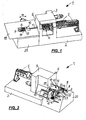
- Fig. 2
- eine perspektivische Ansicht der Biegevorrichtung aus
Fig. 1 , jedoch schräg von hinten und ohne Auflagetisch; - Fig. 3
- eine perspektivische Ansicht der Maschine aus den
Fig. 1 und 2 , wieder schräg von vorne oben, mit entferntem Auflagetisch, nach einem Biegevorgang; - Fig. 4
- die perspektivische Ansicht aus
Fig. 3 , jedoch in der Schnittstellung; - Fig. 5
- eine prinzipielle Detailansicht des oberen Abschnitts der Biegevorrichtung aus den
Fig. 1 bis 4 , mit Blickrichtung parallel zum Auflagetisch, vor dem Einfädeln des Werkstücks in den Biegekopf; - Fig. 6
- die Ansicht aus
Fig. 5 , jedoch nach einem Biegevorgang, sowie - Fig. 7
- die Ansicht aus
Fig. 5 , jedoch in Schnittstellung der Schneideinrichtung.
- Fig. 1
- a perspective basic view of a bending device according to the invention (with support table) obliquely from the top front;
- Fig. 2
- a perspective view of the bending device
Fig. 1 but diagonally from behind and without support table; - Fig. 3
- a perspective view of the machine from the
Fig. 1 and 2 , again diagonally from the front top, with the support table removed, after a bending operation; - Fig. 4
- the perspective view
Fig. 3 , but in the cutting position; - Fig. 5
- a schematic detail view of the upper portion of the bending device of the
Fig. 1 to 4 , viewed in the direction parallel to the support table, before threading the workpiece into the bending head; - Fig. 6
- the view
Fig. 5 , but after a bending process, as well - Fig. 7
- the view
Fig. 5 , but in cutting position of the cutting device.
In den
Die Biegemaschine 1 umfaßt dabei ein Maschinengestellt 2 und ein an diesem angebrachtes Gehäuse 3, in dem eine Vorschubeinrichtung 4 in Form eines Walzeneinzugs mit drei hintereinander geschalteten Walzenpaaren drehbar angebracht ist.The bending
An der Rückseite des Gehäuses 3 sitzen zwei um 90° zueinander versetzte Richtapparate 5, die an die drehbare Vorschubeinrichtung 4 angeschlossen und mit dieser um die Mittelachse eines Werkstücks 11 in Form eines Drahtes verdrehbar sind.At the back of the
Vor der Stirnseite 6 des Gehäuses 3 sind ein Biegekopf 7, der oben einen Biegedorn 8 trägt, der um eine Drehachse 9 (
Bei der Darstellung der
Zur Verdeutlichung des Aufbaus der dargestellten Biegevorrichtung 1 ist in den
Der Biegekopf 7 ist in dem Biegekopfgehäuse 20 angebracht, das an seiner Oberseite eine Öffnung 21 aufweist, durch die der Biegekopf 7 in das Biegekopfgehäuse 20 einfahrbar bzw. aus diesem ausfahrbar angebracht ist. Die Ausfahr- bzw. Einfahrbewegung erfolgt dabei in einer Richtung b (vgl.
Auf dem Biegekopfgehäuse 20 sitzt auch die Schneideinrichtung 10, die, wie
Die
Wie die
Bei der Biegevorrichtung 1 handelt es sich um eine Drahtbiegemaschine, deren Einzug das Werkstück 11, nämlich einen Draht, kontinuierlich von einem (nicht gezeigten) Coil durch die Richteinheiten 5 einzieht. Die drehbare Ausführung der Vorschubeinrichtung 4 und der Richtapparate 5 gestattet es, daß der Draht 11 in unterschiedlichen Ebenen gebogen werden kann.The
Wie
Zwischen den Linearführungen 15 ist, parallel zu diesen, eine in
Wird die Schneideinrichtung 10 entlang der Linearführungen 15 verfahren, bewegt sie sich dabei auf der Oberseite des Biegekopfgehäuses 20, mit einem kleinen Abstand zu diesem, längs einer Fahrbahn, die parallel zur Zuführrichtung des Drahtes 11 verläuft.If the
Zur Durchführung der Biegevorgänge ist der Biegekopf 7 mit dem Biegedorn 8 aus dem Biegekopfgehäuse 20 durch die Öffnung 21 heraus längs Richtung b in eine äußere Endstellung verfahrbar, die als "Wirkstellung" bezeichnet sein soll und in der er mit dem Biegedorn 8 zur Durchführung der gewünschten Biegevorgänge mit dem Draht 11 in Wirkeingriff treten kann. Beim Ausfahren in diese Wirkstellung wird der Draht 11 in das Biegewerkzeug eingefädelt.To carry out the bending operations, the bending
Diese ausgefahrene Wirkstellung ist in den
Werden mehrere Biegevorgänge hintereinander durchgeführt, zwischen denen die Schneideinrichtung 10 nicht aktiviert wird, kann der Biegekopf 7 aus seiner ausgefahrenen Wirkstellung (
Wenn der Biegekopf 7 nun aber bei der Bearbeitung des betreffenden Werkstücks 11 nicht mehr benötigt wird, sondern die Schneideinrichtung 10 zur Aktivierung ansteht, wird der Biegekopf 7 in Richtung b, senkrecht vom Draht 11 weg und durch die Öffnung 21, in das Biegekopfgehäuse 20 eingefahren, bis er im eingefahrenen Zustand seine inaktive Endstellung einnimmt.If the bending
Durch dieses Einfahren des Biegekopfes 7 in das Biegekopfgehäuse 20 wird erreicht, daß der Biegekopf 7 vollständig aus der Fahrbahn, längs derer die Schneideinrichtung 10 in Zuführrichtung des Drahtes 11 am Biegekopfgehäuse 20 verfahrbar ist, verschwunden ist, so daß nunmehr die Schneideinrichtung 10 mit ihrem bis zum Draht 11 vorragenden Tragarm 12 und dessen Messern 13, 14 bis in den Bereich der Öffnung 21 hinein, selbst in den Bereich, den der Biegekopf 7 in seiner ausgefahrenen Wirkstellung belegt, ohne Gefahr einer Kollision mit dem Biegekopf 7 verfahren werden kann.By this retraction of the bending
Die Linearführungen 15 erstrecken sich entsprechend an der Rückseite des Biegekopfgehäuses 20 so weit nach vorne, wie ein Verfahren der Schneideinrichtung 10 stromabwärts gewünscht ist. Bei der Darstellung, wie sie in
Gleichermaßen könnten die Linearführungen 15 aber auch so lange ausgeführt sein (in den Figuren nicht gezeigt), daß sie sich über den Bereich der Öffnung 21 und damit den Bereich des Wirkeingriffs des Biegekopfes 7 hinaus sogar noch bis an das Ende der Stirnseite der Gesamtmaschine erstrecken, um, falls gewünscht, das aus dem Draht 11 fertiggestellte Biegeteil vor dem Schnitt erst noch nach vorne bis an das Ende des Auflagetisches 18 zu bewegen und den Antrieb 25 der Schneideinrichtung 10 erst an der Grenze des Auflagetisches 18 zu aktivieren, wonach das fertiggestellte Teil gleich stirnseitig an der Biegevorrichtung 1 abgenommen werden kann.Equally, however, the
Wenn der Biegekopf 7 in das Biegekopfgehäuse 20 in seine inaktive Endstellung in Richtung b eingefahren und dann die Schneideinrichtung 10 oberhalb der gänzlich offenen Öffnung 21 in Richtung a eingefahren ist, ergibt sich ein Zustand, wie er in
Vergleicht man die Darstellung der
Die
Hierzu ist, wie
Soll bei diesem Vorgang jedoch die Schnittebene genau an der Stelle liegen, an der die letzte Biegung des vorher gebogenen Drahtes 11 beginnt, also möglichst ohne ein kurzes gerades Drahtstück zuvor, dann wird vor Aktivierung der Schneideinrichtung 10 durch Drehen des Einzugs der gebogene Schenkel des Drahtes 11 nach oben verschwenkt, so daß er nicht mehr an der vorderen Seite des vorne liegenden, beweglichen Messers 14 anliegt. Dadurch kann dann der Tragarm 12 noch so weit stromabwärts verfahren werden, bis die zwischen beiden Messern 13, 14 festgelegte Schneidebene 22 an den Beginn der letzten Biegung des Drahtes 11 herangefahren ist, wonach dann die Schneideinrichtung 10 aktiviert wird.However, if in this process the cutting plane is exactly at the point at which the last bend of the previously bent
Um bei der in den Figuren gezeigten Biegevorrichtung 1 ein ungestörtes und kontinuierliches Arbeiten sicherzustellen, ist die Biegevorrichtung 1 an eine (in den Figuren nicht gezeigte) Maschinensteuerung angeschlossen, die so ausgelegt ist, daß sie ein Einfahren der Schneideinrichtung 10 in den Bereich, der vom Biegekopf 7 in dessen ausgefahrener Wirkstellung belegt wird, nur dann zuläßt, wenn der Biegekopf 7 in seine inaktive Endstellung im Biegekopfgehäuse 20 eingefahren ist, in der er sich, wie die Figuren, insbesondere die
Bei der erfindungsgemäßen Biegemaschine wird ganz grundsätzlich eine Anordnung verwirklicht, bei welcher der Biegekopf in eine aktive Wirkstellung, in welcher er in die Fahrbahn der Schneideinrichtung hineinragt, und aus dieser in eine inaktive Endstellung, in der er vollständig außerhalb der Fahrbahn angeordnet ist, und umgekehrt, verfahrbar ist und durch dieses Herausfahren aus der Fahrbahn die nutzbare Verfahrlänge der Fahrbahn so vergrößert wird, daß dann auch ein ganzes oder auch nur teilweises Überfahren des Fahrbahnbereiches, in den der Biegekopf in seiner Wirkstellung hineinragt, ermöglicht wird.In the bending machine according to the invention an arrangement is basically realized, in which the bending head in an active operative position in which it protrudes into the roadway of the cutting device, and from this in an inactive end position in which it is located completely outside the road, and vice versa , is movable and by this retreating from the road, the usable travel length of the roadway is increased so that then a whole or even partial driving over the roadway area, in which the bending head projects into its operative position, is made possible.
Claims (10)
Applications Claiming Priority (1)
| Application Number | Priority Date | Filing Date | Title |
|---|---|---|---|
| DE201110106942 DE102011106942A1 (en) | 2011-07-08 | 2011-07-08 | Bending device for rod-shaped workpieces |
Publications (2)
| Publication Number | Publication Date |
|---|---|
| EP2543452A1 true EP2543452A1 (en) | 2013-01-09 |
| EP2543452B1 EP2543452B1 (en) | 2013-07-24 |
Family
ID=46458106
Family Applications (1)
| Application Number | Title | Priority Date | Filing Date |
|---|---|---|---|
| EP20120004508 Not-in-force EP2543452B1 (en) | 2011-07-08 | 2012-06-14 | Bending device for rod-shaped workpieces |
Country Status (3)
| Country | Link |
|---|---|
| US (1) | US9067255B2 (en) |
| EP (1) | EP2543452B1 (en) |
| DE (1) | DE102011106942A1 (en) |
Cited By (6)
| Publication number | Priority date | Publication date | Assignee | Title |
|---|---|---|---|---|
| CN105290262A (en) * | 2015-11-10 | 2016-02-03 | 建科机械(天津)股份有限公司 | Bending telescopic mechanism of automatic hoop bending machine for steel bars |
| CN106029246A (en) * | 2013-10-14 | 2016-10-12 | Acm自动建设机械股份有限公司 | Apparatus for bending oblong metal products, such as bars, round pieces or metal wires, and corresponding bending method |
| WO2017174654A1 (en) * | 2016-04-08 | 2017-10-12 | Progress Holding A.G. | Bending machine |
| CN110270607A (en) * | 2019-06-04 | 2019-09-24 | 北京机科国创轻量化科学研究院有限公司 | Apparatus for correcting, correcting device, sarong correcting device and antidote |
| CN112091636A (en) * | 2020-11-13 | 2020-12-18 | 山东中茂散热器有限公司 | Metal bending and cutting mechanism |
| CN112338096A (en) * | 2020-10-10 | 2021-02-09 | 宁波昌扬机械工业有限公司 | Novel three-dimensional bending machine |
Families Citing this family (10)
| Publication number | Priority date | Publication date | Assignee | Title |
|---|---|---|---|---|
| JP6344243B2 (en) * | 2013-01-18 | 2018-06-20 | 日本電気株式会社 | Switching element and method for manufacturing semiconductor switching device |
| JP1539124S (en) * | 2014-08-15 | 2015-11-30 | ||
| USD755861S1 (en) * | 2014-08-15 | 2016-05-10 | Trumpf Gmbh + Co. Kg | Bending machine |
| CN104259341B (en) * | 2014-09-05 | 2016-04-27 | 冯广建 | A kind of directed straightening severing for steel bar meter bends multiple purpose aeroplane |
| JP7165976B2 (en) * | 2016-03-30 | 2022-11-07 | ナノブリッジ・セミコンダクター株式会社 | Variable resistance element and method for manufacturing variable resistance element |
| US11007563B2 (en) * | 2016-04-27 | 2021-05-18 | Advanced Orthodontic Solutions | Wire bending machine |
| DE102017101759B3 (en) * | 2017-01-30 | 2018-06-21 | Geobrugg Ag | bender |
| US20190240721A1 (en) * | 2018-02-05 | 2019-08-08 | Kenneth A. Fullick | Machine and Method of Introducing a Camber into a Length of Wire |
| WO2019235796A1 (en) * | 2018-06-04 | 2019-12-12 | 한국기계연구원 | Orthodontic wire bending device |
| JP2022092831A (en) * | 2020-12-11 | 2022-06-23 | セイコーエプソン株式会社 | Software switch program, option selection method, and information processing apparatus |
Citations (7)
| Publication number | Priority date | Publication date | Assignee | Title |
|---|---|---|---|---|
| DE3546449A1 (en) * | 1985-03-12 | 1986-09-25 | Alpha Maschinenbau AG, Zürich | Bending apparatus |
| EP0231092A2 (en) * | 1986-01-29 | 1987-08-05 | Ronald Edward Benton | Bending machine |
| EP0379030A1 (en) * | 1989-01-18 | 1990-07-25 | M.E.P. Macchine Elettroniche Piegatrici S.p.A. | Movable shears upstream of a bending assembly and method to bend the trailing end of bars |
| EP0419443A1 (en) * | 1989-09-20 | 1991-03-27 | EVG Entwicklungs- u. Verwertungs- Gesellschaft m.b.H. | Machine for bending bar material in reinforcing elements for concrete |
| EP0519865A1 (en) * | 1991-06-18 | 1992-12-23 | Max Mitschjeta Ag | Apparatus for bending wire or the like |
| WO1999026739A1 (en) * | 1997-11-26 | 1999-06-03 | M.E.P. Macchine Elettroniche Piegatrici S.P.A. | Bending machine with variable bending tool |
| DE102009024075A1 (en) | 2009-06-05 | 2010-12-09 | Wafios Ag | Bending device for rod-shaped workpieces |
Family Cites Families (21)
| Publication number | Priority date | Publication date | Assignee | Title |
|---|---|---|---|---|
| US1983618A (en) | 1932-11-04 | 1934-12-11 | Pittsburgh Pipe & Coupling Com | Forging apparatus |
| US2464510A (en) | 1945-01-10 | 1949-03-15 | Parker Appliance Co | Tube flaring machine |
| CH477929A (en) | 1967-07-12 | 1969-09-15 | Prescon Corp | Head compression machine |
| FR2231449A1 (en) | 1973-05-28 | 1974-12-27 | Tuyaux Bonna | Machine for cold forging studs on steel rods - has ram operated gripping jaws and pair of guide bushes |
| US3922901A (en) * | 1973-11-29 | 1975-12-02 | Weldun Tool & Engineering Co | Apparatus for bending tubing |
| DE2605795C2 (en) * | 1976-02-13 | 1981-10-08 | Sidro Rohrbogen GmbH, 4980 Bünde | Arrangement for the production of individual pipe bends |
| DE2629796C3 (en) | 1976-07-02 | 1980-12-11 | Laeis-Werke Ag, 5500 Trier | Hydraulic tube and rod end forming machine |
| FR2602160B1 (en) | 1986-08-04 | 1990-07-20 | Latour Fils | MODULAR METHOD AND MACHINE FOR BENDING METAL WIRES |
| EP0272067A3 (en) | 1986-12-18 | 1990-05-09 | Stelco Inc. | Process and apparatus for upset forging of long stands of metal bar stock |
| IT8921687A0 (en) | 1989-09-12 | 1989-09-12 | Blm Spa | PROCEDURE FOR COMPLEMENTARY PROCESSING OF ROD-FORM MATERIAL AND MACHINE FOR EXECUTING THE PROCEDURE. |
| JP2663187B2 (en) | 1989-11-28 | 1997-10-15 | 東芝プラント建設株式会社 | Pipe bender device and its control device |
| US5709121A (en) | 1996-06-21 | 1998-01-20 | Headed Reinforcement Corporation | Method and apparatus for hydraulically upsetting a steel reinforcement bar |
| CN2352285Y (en) | 1998-04-15 | 1999-12-08 | 桂林电子工业学院建筑钢筋机械连接工程研究所 | Machine for upsetting steel bar or steel wire |
| FR2806943B1 (en) | 2000-04-03 | 2002-08-16 | Macsoft | ERASABLE FOLDING NOSE BAR BENDING MACHINE |
| US6508097B2 (en) | 2000-05-19 | 2003-01-21 | Airmo, Inc. | Modular system for expanding and reducing tubing |
| EP1311358B1 (en) | 2000-08-16 | 2005-04-20 | Parker Hannifin GmbH | Device for forming an end area of a workpiece |
| BR0205992B1 (en) | 2001-09-14 | 2010-06-29 | bending machine for profiles such as round reinforcement parts or the like. | |
| ITUD20010197A1 (en) | 2001-11-30 | 2003-05-30 | Piegatrici Macch Elettr | BENDING MACHINE FOR PROFILES, SUCH AS ROUND ARMOR OR SIMILAR |
| CN2526103Y (en) | 2002-01-10 | 2002-12-18 | 燕明 | Upsetting machine |
| DE20205807U1 (en) | 2002-04-12 | 2003-08-21 | Voss Fluid Gmbh & Co Kg | Device for plastically deforming workpieces |
| EP1396296B1 (en) | 2002-09-04 | 2005-07-20 | Schnell S.p.A. | Method for cropping to size and optionally bending profiled elements with bending and shaping machines, particularly profiled elements supplied in bar form |
-
2011
- 2011-07-08 DE DE201110106942 patent/DE102011106942A1/en not_active Withdrawn
-
2012
- 2012-06-14 EP EP20120004508 patent/EP2543452B1/en not_active Not-in-force
- 2012-07-06 US US13/543,149 patent/US9067255B2/en not_active Expired - Fee Related
Patent Citations (9)
| Publication number | Priority date | Publication date | Assignee | Title |
|---|---|---|---|---|
| DE3546449A1 (en) * | 1985-03-12 | 1986-09-25 | Alpha Maschinenbau AG, Zürich | Bending apparatus |
| EP0231092A2 (en) * | 1986-01-29 | 1987-08-05 | Ronald Edward Benton | Bending machine |
| EP0379030A1 (en) * | 1989-01-18 | 1990-07-25 | M.E.P. Macchine Elettroniche Piegatrici S.p.A. | Movable shears upstream of a bending assembly and method to bend the trailing end of bars |
| EP0379030B1 (en) | 1989-01-18 | 1993-09-08 | M.E.P. Macchine Elettroniche Piegatrici S.p.A. | Movable shears upstream of a bending assembly and method to bend the trailing end of bars |
| DE69003116T2 (en) | 1989-01-18 | 1994-01-05 | Piegatrici Macch Elettr | Movable scissors located upstream of a bender and method for bending the rear ends of bars. |
| EP0419443A1 (en) * | 1989-09-20 | 1991-03-27 | EVG Entwicklungs- u. Verwertungs- Gesellschaft m.b.H. | Machine for bending bar material in reinforcing elements for concrete |
| EP0519865A1 (en) * | 1991-06-18 | 1992-12-23 | Max Mitschjeta Ag | Apparatus for bending wire or the like |
| WO1999026739A1 (en) * | 1997-11-26 | 1999-06-03 | M.E.P. Macchine Elettroniche Piegatrici S.P.A. | Bending machine with variable bending tool |
| DE102009024075A1 (en) | 2009-06-05 | 2010-12-09 | Wafios Ag | Bending device for rod-shaped workpieces |
Cited By (9)
| Publication number | Priority date | Publication date | Assignee | Title |
|---|---|---|---|---|
| CN106029246A (en) * | 2013-10-14 | 2016-10-12 | Acm自动建设机械股份有限公司 | Apparatus for bending oblong metal products, such as bars, round pieces or metal wires, and corresponding bending method |
| CN106029246B (en) * | 2013-10-14 | 2019-09-06 | Acm自动建设机械股份有限公司 | For making the curved device of oblong metal product and corresponding bending method |
| CN105290262A (en) * | 2015-11-10 | 2016-02-03 | 建科机械(天津)股份有限公司 | Bending telescopic mechanism of automatic hoop bending machine for steel bars |
| WO2017174654A1 (en) * | 2016-04-08 | 2017-10-12 | Progress Holding A.G. | Bending machine |
| AT518420B1 (en) * | 2016-04-08 | 2017-10-15 | Progress Holding Ag | bending machine |
| AT518420A4 (en) * | 2016-04-08 | 2017-10-15 | Progress Holding Ag | bending machine |
| CN110270607A (en) * | 2019-06-04 | 2019-09-24 | 北京机科国创轻量化科学研究院有限公司 | Apparatus for correcting, correcting device, sarong correcting device and antidote |
| CN112338096A (en) * | 2020-10-10 | 2021-02-09 | 宁波昌扬机械工业有限公司 | Novel three-dimensional bending machine |
| CN112091636A (en) * | 2020-11-13 | 2020-12-18 | 山东中茂散热器有限公司 | Metal bending and cutting mechanism |
Also Published As
| Publication number | Publication date |
|---|---|
| US20130008223A1 (en) | 2013-01-10 |
| DE102011106942A1 (en) | 2013-01-10 |
| EP2543452B1 (en) | 2013-07-24 |
| US9067255B2 (en) | 2015-06-30 |
Similar Documents
| Publication | Publication Date | Title |
|---|---|---|
| EP2543452B1 (en) | Bending device for rod-shaped workpieces | |
| EP2258494B1 (en) | Bending device for rod-shaped workpieces | |
| EP2420344B1 (en) | Method of and device for producing a contour cut in a strip of sheet metal | |
| EP2177287B1 (en) | Support split assembly for gliding side supports of rod and tube-shape workpieces on bending machines | |
| DE3233696C2 (en) | ||
| EP2492041A1 (en) | Flexible unloading device for a pipe processing device ; Supporting device for receiving and supporting a pipe ; Method of unloading a pipe using such unloading device | |
| DE2741576A1 (en) | PROCESSING MACHINE FOR WIRE AND STRIP, IN PARTICULAR PUNCHING AND BENDING MACHINE, WITH SEVERAL TOOLS | |
| EP3645188B1 (en) | Method for producing a bent part and bending machine for performing the method | |
| DE2420690A1 (en) | DEVICE FOR BENDING TUBE SECTIONS | |
| DE2620190C3 (en) | Electric resistance butt welding machine | |
| DE4243054C1 (en) | Device for processing the edge edges of continuously moving plate-shaped workpieces | |
| DE4232289C2 (en) | Method and device for pivoting a window frame in the area of a corner cleaning machine | |
| AT402032B (en) | MACHINE FOR THE PROCESSING OF GRID MATS FROM LENGTHED AND CROSSWIRE WELDED TOGETHER | |
| EP2582479B1 (en) | Method and device for trimming heavy plates | |
| EP3402024B1 (en) | Device for processing cable | |
| EP0622136A1 (en) | Device for the production of reinforcement meshes for concrete panels | |
| DE4422935A1 (en) | Saw device with two rotating saw blades | |
| EP2404691B1 (en) | Rotating ring used for machining profiles | |
| AT501769B1 (en) | DEVICE FOR CROSS-CROSSING TRACKS, IN PARTICULAR OF PALLETS OR PLASTIC TRACKS | |
| EP2756892A1 (en) | Bending device for bar-shaped workpieces | |
| DE19919956C1 (en) | Spring winding machine produces selectively right or left-wound screw springs from wire and has intake rollers feeding wire along guide axis through wire guide with two winding apparatus | |
| EP0618032B1 (en) | Device for the treatment of cornerjoints of window or door frames made of welded plastic profiles | |
| WO2015135909A1 (en) | Wire saw device and use of a wire saw device | |
| DE2921108A1 (en) | WOODWORKING MACHINE FOR TAPING AND LENGTH PROFILING FRAMEWOOD | |
| EP3369685A1 (en) | Device for transporting elongated pieces to a pick-up position and for depositing elongated pieces at this position |
Legal Events
| Date | Code | Title | Description |
|---|---|---|---|
| PUAI | Public reference made under article 153(3) epc to a published international application that has entered the european phase |
Free format text: ORIGINAL CODE: 0009012 |
|
| AK | Designated contracting states |
Kind code of ref document: A1 Designated state(s): AL AT BE BG CH CY CZ DE DK EE ES FI FR GB GR HR HU IE IS IT LI LT LU LV MC MK MT NL NO PL PT RO RS SE SI SK SM TR |
|
| AX | Request for extension of the european patent |
Extension state: BA ME |
|
| 17P | Request for examination filed |
Effective date: 20121220 |
|
| GRAP | Despatch of communication of intention to grant a patent |
Free format text: ORIGINAL CODE: EPIDOSNIGR1 |
|
| RIC1 | Information provided on ipc code assigned before grant |
Ipc: B21F 1/00 20060101AFI20130219BHEP Ipc: B21D 11/12 20060101ALI20130219BHEP Ipc: B21D 7/12 20060101ALI20130219BHEP |
|
| GRAS | Grant fee paid |
Free format text: ORIGINAL CODE: EPIDOSNIGR3 |
|
| GRAA | (expected) grant |
Free format text: ORIGINAL CODE: 0009210 |
|
| AK | Designated contracting states |
Kind code of ref document: B1 Designated state(s): AL AT BE BG CH CY CZ DE DK EE ES FI FR GB GR HR HU IE IS IT LI LT LU LV MC MK MT NL NO PL PT RO RS SE SI SK SM TR |
|
| REG | Reference to a national code |
Ref country code: GB Ref legal event code: FG4D Free format text: NOT ENGLISH |
|
| REG | Reference to a national code |
Ref country code: CH Ref legal event code: EP |
|
| REG | Reference to a national code |
Ref country code: AT Ref legal event code: REF Ref document number: 623096 Country of ref document: AT Kind code of ref document: T Effective date: 20130815 |
|
| REG | Reference to a national code |
Ref country code: IE Ref legal event code: FG4D Free format text: LANGUAGE OF EP DOCUMENT: GERMAN |
|
| REG | Reference to a national code |
Ref country code: DE Ref legal event code: R096 Ref document number: 502012000051 Country of ref document: DE Effective date: 20130919 |
|
| REG | Reference to a national code |
Ref country code: NL Ref legal event code: VDEP Effective date: 20130724 |
|
| REG | Reference to a national code |
Ref country code: LT Ref legal event code: MG4D |
|
| PG25 | Lapsed in a contracting state [announced via postgrant information from national office to epo] |
Ref country code: HR Free format text: LAPSE BECAUSE OF FAILURE TO SUBMIT A TRANSLATION OF THE DESCRIPTION OR TO PAY THE FEE WITHIN THE PRESCRIBED TIME-LIMIT Effective date: 20130724 Ref country code: CY Free format text: LAPSE BECAUSE OF FAILURE TO SUBMIT A TRANSLATION OF THE DESCRIPTION OR TO PAY THE FEE WITHIN THE PRESCRIBED TIME-LIMIT Effective date: 20130918 Ref country code: NO Free format text: LAPSE BECAUSE OF FAILURE TO SUBMIT A TRANSLATION OF THE DESCRIPTION OR TO PAY THE FEE WITHIN THE PRESCRIBED TIME-LIMIT Effective date: 20131024 Ref country code: SE Free format text: LAPSE BECAUSE OF FAILURE TO SUBMIT A TRANSLATION OF THE DESCRIPTION OR TO PAY THE FEE WITHIN THE PRESCRIBED TIME-LIMIT Effective date: 20130724 Ref country code: IS Free format text: LAPSE BECAUSE OF FAILURE TO SUBMIT A TRANSLATION OF THE DESCRIPTION OR TO PAY THE FEE WITHIN THE PRESCRIBED TIME-LIMIT Effective date: 20131124 Ref country code: LT Free format text: LAPSE BECAUSE OF FAILURE TO SUBMIT A TRANSLATION OF THE DESCRIPTION OR TO PAY THE FEE WITHIN THE PRESCRIBED TIME-LIMIT Effective date: 20130724 Ref country code: PT Free format text: LAPSE BECAUSE OF FAILURE TO SUBMIT A TRANSLATION OF THE DESCRIPTION OR TO PAY THE FEE WITHIN THE PRESCRIBED TIME-LIMIT Effective date: 20131125 |
|
| PG25 | Lapsed in a contracting state [announced via postgrant information from national office to epo] |
Ref country code: NL Free format text: LAPSE BECAUSE OF FAILURE TO SUBMIT A TRANSLATION OF THE DESCRIPTION OR TO PAY THE FEE WITHIN THE PRESCRIBED TIME-LIMIT Effective date: 20130724 Ref country code: LV Free format text: LAPSE BECAUSE OF FAILURE TO SUBMIT A TRANSLATION OF THE DESCRIPTION OR TO PAY THE FEE WITHIN THE PRESCRIBED TIME-LIMIT Effective date: 20130724 Ref country code: GR Free format text: LAPSE BECAUSE OF FAILURE TO SUBMIT A TRANSLATION OF THE DESCRIPTION OR TO PAY THE FEE WITHIN THE PRESCRIBED TIME-LIMIT Effective date: 20131025 Ref country code: FI Free format text: LAPSE BECAUSE OF FAILURE TO SUBMIT A TRANSLATION OF THE DESCRIPTION OR TO PAY THE FEE WITHIN THE PRESCRIBED TIME-LIMIT Effective date: 20130724 Ref country code: PL Free format text: LAPSE BECAUSE OF FAILURE TO SUBMIT A TRANSLATION OF THE DESCRIPTION OR TO PAY THE FEE WITHIN THE PRESCRIBED TIME-LIMIT Effective date: 20130724 |
|
| PG25 | Lapsed in a contracting state [announced via postgrant information from national office to epo] |
Ref country code: CY Free format text: LAPSE BECAUSE OF FAILURE TO SUBMIT A TRANSLATION OF THE DESCRIPTION OR TO PAY THE FEE WITHIN THE PRESCRIBED TIME-LIMIT Effective date: 20130724 |
|
| PG25 | Lapsed in a contracting state [announced via postgrant information from national office to epo] |
Ref country code: SK Free format text: LAPSE BECAUSE OF FAILURE TO SUBMIT A TRANSLATION OF THE DESCRIPTION OR TO PAY THE FEE WITHIN THE PRESCRIBED TIME-LIMIT Effective date: 20130724 Ref country code: CZ Free format text: LAPSE BECAUSE OF FAILURE TO SUBMIT A TRANSLATION OF THE DESCRIPTION OR TO PAY THE FEE WITHIN THE PRESCRIBED TIME-LIMIT Effective date: 20130724 Ref country code: EE Free format text: LAPSE BECAUSE OF FAILURE TO SUBMIT A TRANSLATION OF THE DESCRIPTION OR TO PAY THE FEE WITHIN THE PRESCRIBED TIME-LIMIT Effective date: 20130724 Ref country code: DK Free format text: LAPSE BECAUSE OF FAILURE TO SUBMIT A TRANSLATION OF THE DESCRIPTION OR TO PAY THE FEE WITHIN THE PRESCRIBED TIME-LIMIT Effective date: 20130724 Ref country code: RO Free format text: LAPSE BECAUSE OF FAILURE TO SUBMIT A TRANSLATION OF THE DESCRIPTION OR TO PAY THE FEE WITHIN THE PRESCRIBED TIME-LIMIT Effective date: 20130724 |
|
| PG25 | Lapsed in a contracting state [announced via postgrant information from national office to epo] |
Ref country code: ES Free format text: LAPSE BECAUSE OF FAILURE TO SUBMIT A TRANSLATION OF THE DESCRIPTION OR TO PAY THE FEE WITHIN THE PRESCRIBED TIME-LIMIT Effective date: 20130724 |
|
| PLBE | No opposition filed within time limit |
Free format text: ORIGINAL CODE: 0009261 |
|
| STAA | Information on the status of an ep patent application or granted ep patent |
Free format text: STATUS: NO OPPOSITION FILED WITHIN TIME LIMIT |
|
| 26N | No opposition filed |
Effective date: 20140425 |
|
| REG | Reference to a national code |
Ref country code: DE Ref legal event code: R097 Ref document number: 502012000051 Country of ref document: DE Effective date: 20140425 |
|
| PG25 | Lapsed in a contracting state [announced via postgrant information from national office to epo] |
Ref country code: MC Free format text: LAPSE BECAUSE OF FAILURE TO SUBMIT A TRANSLATION OF THE DESCRIPTION OR TO PAY THE FEE WITHIN THE PRESCRIBED TIME-LIMIT Effective date: 20130724 Ref country code: LU Free format text: LAPSE BECAUSE OF FAILURE TO SUBMIT A TRANSLATION OF THE DESCRIPTION OR TO PAY THE FEE WITHIN THE PRESCRIBED TIME-LIMIT Effective date: 20140614 |
|
| REG | Reference to a national code |
Ref country code: IE Ref legal event code: MM4A |
|
| PG25 | Lapsed in a contracting state [announced via postgrant information from national office to epo] |
Ref country code: IE Free format text: LAPSE BECAUSE OF NON-PAYMENT OF DUE FEES Effective date: 20140614 |
|
| REG | Reference to a national code |
Ref country code: CH Ref legal event code: PL |
|
| PG25 | Lapsed in a contracting state [announced via postgrant information from national office to epo] |
Ref country code: MT Free format text: LAPSE BECAUSE OF FAILURE TO SUBMIT A TRANSLATION OF THE DESCRIPTION OR TO PAY THE FEE WITHIN THE PRESCRIBED TIME-LIMIT Effective date: 20130724 |
|
| PG25 | Lapsed in a contracting state [announced via postgrant information from national office to epo] |
Ref country code: CH Free format text: LAPSE BECAUSE OF NON-PAYMENT OF DUE FEES Effective date: 20150630 Ref country code: SM Free format text: LAPSE BECAUSE OF FAILURE TO SUBMIT A TRANSLATION OF THE DESCRIPTION OR TO PAY THE FEE WITHIN THE PRESCRIBED TIME-LIMIT Effective date: 20130724 Ref country code: LI Free format text: LAPSE BECAUSE OF NON-PAYMENT OF DUE FEES Effective date: 20150630 |
|
| REG | Reference to a national code |
Ref country code: FR Ref legal event code: PLFP Year of fee payment: 5 |
|
| PG25 | Lapsed in a contracting state [announced via postgrant information from national office to epo] |
Ref country code: BG Free format text: LAPSE BECAUSE OF FAILURE TO SUBMIT A TRANSLATION OF THE DESCRIPTION OR TO PAY THE FEE WITHIN THE PRESCRIBED TIME-LIMIT Effective date: 20130724 Ref country code: RS Free format text: LAPSE BECAUSE OF FAILURE TO SUBMIT A TRANSLATION OF THE DESCRIPTION OR TO PAY THE FEE WITHIN THE PRESCRIBED TIME-LIMIT Effective date: 20130724 |
|
| PG25 | Lapsed in a contracting state [announced via postgrant information from national office to epo] |
Ref country code: HU Free format text: LAPSE BECAUSE OF FAILURE TO SUBMIT A TRANSLATION OF THE DESCRIPTION OR TO PAY THE FEE WITHIN THE PRESCRIBED TIME-LIMIT; INVALID AB INITIO Effective date: 20120614 Ref country code: TR Free format text: LAPSE BECAUSE OF FAILURE TO SUBMIT A TRANSLATION OF THE DESCRIPTION OR TO PAY THE FEE WITHIN THE PRESCRIBED TIME-LIMIT Effective date: 20130724 Ref country code: SI Free format text: LAPSE BECAUSE OF FAILURE TO SUBMIT A TRANSLATION OF THE DESCRIPTION OR TO PAY THE FEE WITHIN THE PRESCRIBED TIME-LIMIT Effective date: 20130724 Ref country code: BE Free format text: LAPSE BECAUSE OF FAILURE TO SUBMIT A TRANSLATION OF THE DESCRIPTION OR TO PAY THE FEE WITHIN THE PRESCRIBED TIME-LIMIT Effective date: 20140630 |
|
| GBPC | Gb: european patent ceased through non-payment of renewal fee |
Effective date: 20160614 |
|
| PG25 | Lapsed in a contracting state [announced via postgrant information from national office to epo] |
Ref country code: GB Free format text: LAPSE BECAUSE OF NON-PAYMENT OF DUE FEES Effective date: 20160614 |
|
| REG | Reference to a national code |
Ref country code: FR Ref legal event code: PLFP Year of fee payment: 6 |
|
| REG | Reference to a national code |
Ref country code: FR Ref legal event code: PLFP Year of fee payment: 7 |
|
| PG25 | Lapsed in a contracting state [announced via postgrant information from national office to epo] |
Ref country code: MK Free format text: LAPSE BECAUSE OF FAILURE TO SUBMIT A TRANSLATION OF THE DESCRIPTION OR TO PAY THE FEE WITHIN THE PRESCRIBED TIME-LIMIT Effective date: 20130724 |
|
| REG | Reference to a national code |
Ref country code: AT Ref legal event code: MM01 Ref document number: 623096 Country of ref document: AT Kind code of ref document: T Effective date: 20170614 |
|
| PG25 | Lapsed in a contracting state [announced via postgrant information from national office to epo] |
Ref country code: AL Free format text: LAPSE BECAUSE OF FAILURE TO SUBMIT A TRANSLATION OF THE DESCRIPTION OR TO PAY THE FEE WITHIN THE PRESCRIBED TIME-LIMIT Effective date: 20130724 |
|
| PG25 | Lapsed in a contracting state [announced via postgrant information from national office to epo] |
Ref country code: AT Free format text: LAPSE BECAUSE OF NON-PAYMENT OF DUE FEES Effective date: 20170614 |
|
| PGFP | Annual fee paid to national office [announced via postgrant information from national office to epo] |
Ref country code: FR Payment date: 20210621 Year of fee payment: 10 Ref country code: IT Payment date: 20210630 Year of fee payment: 10 |
|
| PGFP | Annual fee paid to national office [announced via postgrant information from national office to epo] |
Ref country code: DE Payment date: 20220621 Year of fee payment: 11 |
|
| PG25 | Lapsed in a contracting state [announced via postgrant information from national office to epo] |
Ref country code: FR Free format text: LAPSE BECAUSE OF NON-PAYMENT OF DUE FEES Effective date: 20220630 |
|
| PG25 | Lapsed in a contracting state [announced via postgrant information from national office to epo] |
Ref country code: IT Free format text: LAPSE BECAUSE OF NON-PAYMENT OF DUE FEES Effective date: 20220614 |
|
| REG | Reference to a national code |
Ref country code: DE Ref legal event code: R119 Ref document number: 502012000051 Country of ref document: DE |