EP2529702A1 - Reinforced implant made of biocompatible ceramic and method for manufacturing same - Google Patents
Reinforced implant made of biocompatible ceramic and method for manufacturing same Download PDFInfo
- Publication number
- EP2529702A1 EP2529702A1 EP12168336A EP12168336A EP2529702A1 EP 2529702 A1 EP2529702 A1 EP 2529702A1 EP 12168336 A EP12168336 A EP 12168336A EP 12168336 A EP12168336 A EP 12168336A EP 2529702 A1 EP2529702 A1 EP 2529702A1
- Authority
- EP
- European Patent Office
- Prior art keywords
- implant
- cranial
- skull
- implant body
- porous
- Prior art date
- Legal status (The legal status is an assumption and is not a legal conclusion. Google has not performed a legal analysis and makes no representation as to the accuracy of the status listed.)
- Granted
Links
Images


Classifications
-
- A—HUMAN NECESSITIES
- A61—MEDICAL OR VETERINARY SCIENCE; HYGIENE
- A61F—FILTERS IMPLANTABLE INTO BLOOD VESSELS; PROSTHESES; DEVICES PROVIDING PATENCY TO, OR PREVENTING COLLAPSING OF, TUBULAR STRUCTURES OF THE BODY, e.g. STENTS; ORTHOPAEDIC, NURSING OR CONTRACEPTIVE DEVICES; FOMENTATION; TREATMENT OR PROTECTION OF EYES OR EARS; BANDAGES, DRESSINGS OR ABSORBENT PADS; FIRST-AID KITS
- A61F2/00—Filters implantable into blood vessels; Prostheses, i.e. artificial substitutes or replacements for parts of the body; Appliances for connecting them with the body; Devices providing patency to, or preventing collapsing of, tubular structures of the body, e.g. stents
- A61F2/02—Prostheses implantable into the body
- A61F2/28—Bones
- A61F2/2875—Skull or cranium
-
- A—HUMAN NECESSITIES
- A61—MEDICAL OR VETERINARY SCIENCE; HYGIENE
- A61F—FILTERS IMPLANTABLE INTO BLOOD VESSELS; PROSTHESES; DEVICES PROVIDING PATENCY TO, OR PREVENTING COLLAPSING OF, TUBULAR STRUCTURES OF THE BODY, e.g. STENTS; ORTHOPAEDIC, NURSING OR CONTRACEPTIVE DEVICES; FOMENTATION; TREATMENT OR PROTECTION OF EYES OR EARS; BANDAGES, DRESSINGS OR ABSORBENT PADS; FIRST-AID KITS
- A61F2/00—Filters implantable into blood vessels; Prostheses, i.e. artificial substitutes or replacements for parts of the body; Appliances for connecting them with the body; Devices providing patency to, or preventing collapsing of, tubular structures of the body, e.g. stents
- A61F2/02—Prostheses implantable into the body
- A61F2/30—Joints
- A61F2/3094—Designing or manufacturing processes
- A61F2/30942—Designing or manufacturing processes for designing or making customized prostheses, e.g. using templates, CT or NMR scans, finite-element analysis or CAD-CAM techniques
-
- A—HUMAN NECESSITIES
- A61—MEDICAL OR VETERINARY SCIENCE; HYGIENE
- A61L—METHODS OR APPARATUS FOR STERILISING MATERIALS OR OBJECTS IN GENERAL; DISINFECTION, STERILISATION OR DEODORISATION OF AIR; CHEMICAL ASPECTS OF BANDAGES, DRESSINGS, ABSORBENT PADS OR SURGICAL ARTICLES; MATERIALS FOR BANDAGES, DRESSINGS, ABSORBENT PADS OR SURGICAL ARTICLES
- A61L27/00—Materials for grafts or prostheses or for coating grafts or prostheses
- A61L27/02—Inorganic materials
- A61L27/12—Phosphorus-containing materials, e.g. apatite
-
- A—HUMAN NECESSITIES
- A61—MEDICAL OR VETERINARY SCIENCE; HYGIENE
- A61L—METHODS OR APPARATUS FOR STERILISING MATERIALS OR OBJECTS IN GENERAL; DISINFECTION, STERILISATION OR DEODORISATION OF AIR; CHEMICAL ASPECTS OF BANDAGES, DRESSINGS, ABSORBENT PADS OR SURGICAL ARTICLES; MATERIALS FOR BANDAGES, DRESSINGS, ABSORBENT PADS OR SURGICAL ARTICLES
- A61L27/00—Materials for grafts or prostheses or for coating grafts or prostheses
- A61L27/50—Materials characterised by their function or physical properties, e.g. injectable or lubricating compositions, shape-memory materials, surface modified materials
- A61L27/56—Porous materials, e.g. foams or sponges
-
- A—HUMAN NECESSITIES
- A61—MEDICAL OR VETERINARY SCIENCE; HYGIENE
- A61B—DIAGNOSIS; SURGERY; IDENTIFICATION
- A61B17/00—Surgical instruments, devices or methods, e.g. tourniquets
- A61B17/56—Surgical instruments or methods for treatment of bones or joints; Devices specially adapted therefor
- A61B17/58—Surgical instruments or methods for treatment of bones or joints; Devices specially adapted therefor for osteosynthesis, e.g. bone plates, screws, setting implements or the like
- A61B17/68—Internal fixation devices, including fasteners and spinal fixators, even if a part thereof projects from the skin
- A61B17/84—Fasteners therefor or fasteners being internal fixation devices
- A61B17/842—Flexible wires, bands or straps
-
- A—HUMAN NECESSITIES
- A61—MEDICAL OR VETERINARY SCIENCE; HYGIENE
- A61F—FILTERS IMPLANTABLE INTO BLOOD VESSELS; PROSTHESES; DEVICES PROVIDING PATENCY TO, OR PREVENTING COLLAPSING OF, TUBULAR STRUCTURES OF THE BODY, e.g. STENTS; ORTHOPAEDIC, NURSING OR CONTRACEPTIVE DEVICES; FOMENTATION; TREATMENT OR PROTECTION OF EYES OR EARS; BANDAGES, DRESSINGS OR ABSORBENT PADS; FIRST-AID KITS
- A61F2/00—Filters implantable into blood vessels; Prostheses, i.e. artificial substitutes or replacements for parts of the body; Appliances for connecting them with the body; Devices providing patency to, or preventing collapsing of, tubular structures of the body, e.g. stents
- A61F2/02—Prostheses implantable into the body
- A61F2/30—Joints
- A61F2002/30001—Additional features of subject-matter classified in A61F2/28, A61F2/30 and subgroups thereof
- A61F2002/30003—Material related properties of the prosthesis or of a coating on the prosthesis
- A61F2002/30004—Material related properties of the prosthesis or of a coating on the prosthesis the prosthesis being made from materials having different values of a given property at different locations within the same prosthesis
- A61F2002/30011—Material related properties of the prosthesis or of a coating on the prosthesis the prosthesis being made from materials having different values of a given property at different locations within the same prosthesis differing in porosity
-
- A—HUMAN NECESSITIES
- A61—MEDICAL OR VETERINARY SCIENCE; HYGIENE
- A61F—FILTERS IMPLANTABLE INTO BLOOD VESSELS; PROSTHESES; DEVICES PROVIDING PATENCY TO, OR PREVENTING COLLAPSING OF, TUBULAR STRUCTURES OF THE BODY, e.g. STENTS; ORTHOPAEDIC, NURSING OR CONTRACEPTIVE DEVICES; FOMENTATION; TREATMENT OR PROTECTION OF EYES OR EARS; BANDAGES, DRESSINGS OR ABSORBENT PADS; FIRST-AID KITS
- A61F2/00—Filters implantable into blood vessels; Prostheses, i.e. artificial substitutes or replacements for parts of the body; Appliances for connecting them with the body; Devices providing patency to, or preventing collapsing of, tubular structures of the body, e.g. stents
- A61F2/02—Prostheses implantable into the body
- A61F2/30—Joints
- A61F2/30767—Special external or bone-contacting surface, e.g. coating for improving bone ingrowth
- A61F2/30771—Special external or bone-contacting surface, e.g. coating for improving bone ingrowth applied in original prostheses, e.g. holes or grooves
- A61F2002/30878—Special external or bone-contacting surface, e.g. coating for improving bone ingrowth applied in original prostheses, e.g. holes or grooves with non-sharp protrusions, for instance contacting the bone for anchoring, e.g. keels, pegs, pins, posts, shanks, stems, struts
-
- A—HUMAN NECESSITIES
- A61—MEDICAL OR VETERINARY SCIENCE; HYGIENE
- A61F—FILTERS IMPLANTABLE INTO BLOOD VESSELS; PROSTHESES; DEVICES PROVIDING PATENCY TO, OR PREVENTING COLLAPSING OF, TUBULAR STRUCTURES OF THE BODY, e.g. STENTS; ORTHOPAEDIC, NURSING OR CONTRACEPTIVE DEVICES; FOMENTATION; TREATMENT OR PROTECTION OF EYES OR EARS; BANDAGES, DRESSINGS OR ABSORBENT PADS; FIRST-AID KITS
- A61F2/00—Filters implantable into blood vessels; Prostheses, i.e. artificial substitutes or replacements for parts of the body; Appliances for connecting them with the body; Devices providing patency to, or preventing collapsing of, tubular structures of the body, e.g. stents
- A61F2/02—Prostheses implantable into the body
- A61F2/30—Joints
- A61F2/30767—Special external or bone-contacting surface, e.g. coating for improving bone ingrowth
- A61F2002/3092—Special external or bone-contacting surface, e.g. coating for improving bone ingrowth having an open-celled or open-pored structure
-
- A—HUMAN NECESSITIES
- A61—MEDICAL OR VETERINARY SCIENCE; HYGIENE
- A61F—FILTERS IMPLANTABLE INTO BLOOD VESSELS; PROSTHESES; DEVICES PROVIDING PATENCY TO, OR PREVENTING COLLAPSING OF, TUBULAR STRUCTURES OF THE BODY, e.g. STENTS; ORTHOPAEDIC, NURSING OR CONTRACEPTIVE DEVICES; FOMENTATION; TREATMENT OR PROTECTION OF EYES OR EARS; BANDAGES, DRESSINGS OR ABSORBENT PADS; FIRST-AID KITS
- A61F2/00—Filters implantable into blood vessels; Prostheses, i.e. artificial substitutes or replacements for parts of the body; Appliances for connecting them with the body; Devices providing patency to, or preventing collapsing of, tubular structures of the body, e.g. stents
- A61F2/02—Prostheses implantable into the body
- A61F2/30—Joints
- A61F2/3094—Designing or manufacturing processes
- A61F2/30942—Designing or manufacturing processes for designing or making customized prostheses, e.g. using templates, CT or NMR scans, finite-element analysis or CAD-CAM techniques
- A61F2002/30948—Designing or manufacturing processes for designing or making customized prostheses, e.g. using templates, CT or NMR scans, finite-element analysis or CAD-CAM techniques using computerized tomography, i.e. CT scans
-
- A—HUMAN NECESSITIES
- A61—MEDICAL OR VETERINARY SCIENCE; HYGIENE
- A61F—FILTERS IMPLANTABLE INTO BLOOD VESSELS; PROSTHESES; DEVICES PROVIDING PATENCY TO, OR PREVENTING COLLAPSING OF, TUBULAR STRUCTURES OF THE BODY, e.g. STENTS; ORTHOPAEDIC, NURSING OR CONTRACEPTIVE DEVICES; FOMENTATION; TREATMENT OR PROTECTION OF EYES OR EARS; BANDAGES, DRESSINGS OR ABSORBENT PADS; FIRST-AID KITS
- A61F2/00—Filters implantable into blood vessels; Prostheses, i.e. artificial substitutes or replacements for parts of the body; Appliances for connecting them with the body; Devices providing patency to, or preventing collapsing of, tubular structures of the body, e.g. stents
- A61F2/02—Prostheses implantable into the body
- A61F2/30—Joints
- A61F2/3094—Designing or manufacturing processes
- A61F2/30942—Designing or manufacturing processes for designing or making customized prostheses, e.g. using templates, CT or NMR scans, finite-element analysis or CAD-CAM techniques
- A61F2002/30952—Designing or manufacturing processes for designing or making customized prostheses, e.g. using templates, CT or NMR scans, finite-element analysis or CAD-CAM techniques using CAD-CAM techniques or NC-techniques
-
- A—HUMAN NECESSITIES
- A61—MEDICAL OR VETERINARY SCIENCE; HYGIENE
- A61F—FILTERS IMPLANTABLE INTO BLOOD VESSELS; PROSTHESES; DEVICES PROVIDING PATENCY TO, OR PREVENTING COLLAPSING OF, TUBULAR STRUCTURES OF THE BODY, e.g. STENTS; ORTHOPAEDIC, NURSING OR CONTRACEPTIVE DEVICES; FOMENTATION; TREATMENT OR PROTECTION OF EYES OR EARS; BANDAGES, DRESSINGS OR ABSORBENT PADS; FIRST-AID KITS
- A61F2/00—Filters implantable into blood vessels; Prostheses, i.e. artificial substitutes or replacements for parts of the body; Appliances for connecting them with the body; Devices providing patency to, or preventing collapsing of, tubular structures of the body, e.g. stents
- A61F2/02—Prostheses implantable into the body
- A61F2/30—Joints
- A61F2/3094—Designing or manufacturing processes
- A61F2/30942—Designing or manufacturing processes for designing or making customized prostheses, e.g. using templates, CT or NMR scans, finite-element analysis or CAD-CAM techniques
- A61F2002/30962—Designing or manufacturing processes for designing or making customized prostheses, e.g. using templates, CT or NMR scans, finite-element analysis or CAD-CAM techniques using stereolithography
-
- A—HUMAN NECESSITIES
- A61—MEDICAL OR VETERINARY SCIENCE; HYGIENE
- A61F—FILTERS IMPLANTABLE INTO BLOOD VESSELS; PROSTHESES; DEVICES PROVIDING PATENCY TO, OR PREVENTING COLLAPSING OF, TUBULAR STRUCTURES OF THE BODY, e.g. STENTS; ORTHOPAEDIC, NURSING OR CONTRACEPTIVE DEVICES; FOMENTATION; TREATMENT OR PROTECTION OF EYES OR EARS; BANDAGES, DRESSINGS OR ABSORBENT PADS; FIRST-AID KITS
- A61F2310/00—Prostheses classified in A61F2/28 or A61F2/30 - A61F2/44 being constructed from or coated with a particular material
- A61F2310/00005—The prosthesis being constructed from a particular material
- A61F2310/00179—Ceramics or ceramic-like structures
- A61F2310/00185—Ceramics or ceramic-like structures based on metal oxides
- A61F2310/00203—Ceramics or ceramic-like structures based on metal oxides containing alumina or aluminium oxide
-
- A—HUMAN NECESSITIES
- A61—MEDICAL OR VETERINARY SCIENCE; HYGIENE
- A61F—FILTERS IMPLANTABLE INTO BLOOD VESSELS; PROSTHESES; DEVICES PROVIDING PATENCY TO, OR PREVENTING COLLAPSING OF, TUBULAR STRUCTURES OF THE BODY, e.g. STENTS; ORTHOPAEDIC, NURSING OR CONTRACEPTIVE DEVICES; FOMENTATION; TREATMENT OR PROTECTION OF EYES OR EARS; BANDAGES, DRESSINGS OR ABSORBENT PADS; FIRST-AID KITS
- A61F2310/00—Prostheses classified in A61F2/28 or A61F2/30 - A61F2/44 being constructed from or coated with a particular material
- A61F2310/00005—The prosthesis being constructed from a particular material
- A61F2310/00179—Ceramics or ceramic-like structures
- A61F2310/00293—Ceramics or ceramic-like structures containing a phosphorus-containing compound, e.g. apatite
-
- A—HUMAN NECESSITIES
- A61—MEDICAL OR VETERINARY SCIENCE; HYGIENE
- A61L—METHODS OR APPARATUS FOR STERILISING MATERIALS OR OBJECTS IN GENERAL; DISINFECTION, STERILISATION OR DEODORISATION OF AIR; CHEMICAL ASPECTS OF BANDAGES, DRESSINGS, ABSORBENT PADS OR SURGICAL ARTICLES; MATERIALS FOR BANDAGES, DRESSINGS, ABSORBENT PADS OR SURGICAL ARTICLES
- A61L2430/00—Materials or treatment for tissue regeneration
- A61L2430/02—Materials or treatment for tissue regeneration for reconstruction of bones; weight-bearing implants
-
- B—PERFORMING OPERATIONS; TRANSPORTING
- B33—ADDITIVE MANUFACTURING TECHNOLOGY
- B33Y—ADDITIVE MANUFACTURING, i.e. MANUFACTURING OF THREE-DIMENSIONAL [3-D] OBJECTS BY ADDITIVE DEPOSITION, ADDITIVE AGGLOMERATION OR ADDITIVE LAYERING, e.g. BY 3-D PRINTING, STEREOLITHOGRAPHY OR SELECTIVE LASER SINTERING
- B33Y80/00—Products made by additive manufacturing
Definitions
- the present invention relates to the field of bone implants, including cranial implants intended to fill a bone defect in the skull of a human being or a mammal.
- Cranial defects can have various origins and occur in particular following a developmental abnormality, a bone disease or traumas that have led to fractures of the skull. They may also be the result of a neurosurgery operation, such as a decompressive craniectomy performed in the case of post-traumatic cerebral edema, or an operation to extract a brain tumor.
- cranioplasty a skull reconstruction operation in which is inserted and fixed in the skull a bone implant intended to fill the bone defect.
- the ideal material for cranioplasty implants must be resistant, biocompatible, to eliminate the risk of inflammation, rejection and infection, and must be able to integrate into the living bone structure to eventually become part of it.
- the integration of the implant into the native tissue is via a process of bone cell migration, osteoblasts, into the implant, which will contribute to the formation of new bone tissue.
- Ceramics are also advantageous materials for the manufacture of cranioplasty implants. Hydroxyapatite or calcium phosphate implants are thus known, materials chosen for their appropriate biocompatibility and osteoconductivity.
- the patent application WO2005 / 094730 A1 describes a porous ceramic cranial implant manufacturing method. After acquiring a three-dimensional image of the patient's skull, the bone defect is modeled by computer-assisted design. A prototype implant is then made by rapid prototyping, which will be used to manufacture a mold made of calcium sulphate, resin or silicone rubber. Finally, the mold is used to make the porous ceramic implant.
- Ceramics such as hydroxyapatite or calcium triphosphate, have interesting properties for the manufacture of implants. Their chemical composition, based on calcium phosphate, is close to that of bone, and gives them good biocompatibility. In addition, ceramics can be made porous and therefore have a good osteoconductivity that allows implants to integrate well with bone tissue.
- the document WO 00/41083 A1 discloses a cranial implant being made of biocompatible ceramic and comprising an implant body having a shape and dimensions substantially corresponding to the shape and dimensions of the cranial defect to be filled.
- the document US2006 / 0224242 A1 discloses a composite surgical implant consisting of a thermoplastic resin sheet and a combination a metal mesh and metal plates.
- the document WO 95/07509 A1 discloses a stereolithographic construction method of models including prostheses.
- the document WO 2007/045000 A2 discloses methods, techniques, materials, devices and uses for manufacturing and adjusting biocompatible implants.
- the present invention therefore aims to improve the mechanical strength of ceramic cranial implants, so as to avoid deformation and embrittlement of the implants during their manufacture.
- the invention also aims to improve the resistance of ceramic cranial implants and to allow the manufacture of large ceramic cranial implants.
- the present application relates to a cranial implant for filling a cranial defect of the skull of a mammal or a human being, said cranial implant being made of biocompatible ceramic and comprising an implant body having a shape and dimensions corresponding substantially to the shape and dimensions of the cranial defect to be filled, the implant body comprising an outer face turned towards the outside of the skull and an inner face turned towards the inside of the skull when the implant is in place on the skull, characterized in that the cranial implant comprises one or more reinforcing elements protruding from the inner face of the implant body.
- the presence of the reinforcing element or elements makes it possible to improve the mechanical strength of the implant at all the manufacturing steps of the part. In particular, they make it possible to avoid deformation during debinding and sintering, as well as the appearance of weakening zones, such as microcracks in the implant.
- the reinforcing elements may consist of any projecting structure capable of reinforcing the mechanical strength of the implant. They may in particular consist of reinforcing strips, or any other geometric element.
- the ceramic is for example alumina, a ceramic based on calcium phosphate, such as hydroxyapatite, tricalcium phosphate, or a mixture thereof.
- the reinforcing element or elements are preferably made in one piece with the body of the implant.
- This design is advantageous over a design consisting of one or more reinforcing elements reported and fixed to the body of the implant after manufacture thereof. In addition to saving time provided by this design, it also avoids the risk of poor attachment and / or detachment of the reinforcing element or elements, while increasing their reinforcing capacity.
- the reinforcing element or elements protrude over a thickness less than the distance separating the internal face of the implant body from the external face of the underlying anatomical structure, such as the dura mater of the mammal or the human being receiving the implant, when the implant is in place on the skull.
- a plurality of openings are provided in at least one of the reinforcing elements, the openings being provided on the upper face of the reinforcing element (s) and / or on the lateral face (s) of the element or elements. reinforcement.
- Debinding is a heat treatment that follows the manufacture of the implant from a composition containing a polymerizable resin. Debinding is used to burn the unpolymerized resin.
- the openings in the reinforcing element or elements have the function of facilitating the release of the unpolymerized resin vapors during debinding.
- the cranial implant preferably comprises at least two regions whose porosities are different.
- the implant may comprise at least one porous region and at least one non-porous region.
- the porous region or regions are intended to be colonized by bone cells such as osteoblasts.
- the pores are open and preferably interconnected, and their dimensions are chosen to allow good penetration of the bone cells therein.
- the nonporous regions are intended to mechanically strengthen the implant.
- the implant body is preferably porous in the vicinity of a portion of the surface of the implant body and is non-porous at the heart of the implant body.
- the bone cells do not penetrate the entire thickness of the implant body. It is therefore advantageous to providing the porous regions in the vicinity of the surface of the implant body, and providing a non-porous structure in the heart of the implant body that enhances the strength of the implant.
- the reinforcement element or elements are preferably non-porous, which increases their ability to mechanically strengthen the part.
- One possible method of fixation is to secure the implant with sutures.
- the implant body may comprise, in the vicinity of its periphery, through-fastening openings.
- These openings are for passing the suture for fixation with the bone region surrounding the cranial defect.
- the attachment openings are preferably surrounded by a non-porous attachment region, mechanically stronger than a porous region.
- the reinforcing elements may take different forms which will be chosen in particular according to the shape of the implant, according to the position of the cranial defect and according to the underlying anatomical structures.
- the cranial implant comprises a plurality of reinforcing elements, at least a part of which consists of reinforcing strips and a central element, such as a ring or a circle, the reinforcing strips extending in a star shape towards the periphery of the implant from the central element.
- the cranial implant comprises a plurality of reinforcing elements, at least a portion of which consists of reinforcing strips forming a grid.
- stereolithography As an example of rapid prototyping technique, stereolithography can be mentioned.
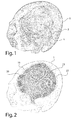
- a skull 1 according to a perspective view.
- This skull has a cranial defect 2 very important.
- the cranial defect 2 takes the form of a cap that covers a very large part of the frontal bone and part of the parietal bone on the left side and in the center of the skull.
- the defect extends frontally to the edge of the left orbit of the skull and includes a tongue-shaped portion protruding from the cap and descending to the left side of the left orbit.
- the cranial defect reveals dura 3, upper membrane of the meninges whose particular function is to protect the brain.
- FIG. 2 On the Figure 2 is represented the skull of the Figure 1 carrying a cranial implant 10 according to a first embodiment of the invention.
- This implant includes a implant body 20 which comprises an outer face 21 facing the outside of the skull and an inner face, not visible on the Figure 2 and turned towards the inside of the skull.
- the shape of the implant substantially reproduces the shape of the cranial defect.
- the implant therefore has the overall shape of a cap and has a tongue-shaped portion that comes to marry the corresponding part of the cranial defect.
- the implant body 20 comprises, at its outer face 21, a bearing rim 23 which slightly exceeds the cranial defect.
- the dimensions of the implant body 20 correspond to the dimensions of the cranial defect 2, so that the implant 10 comes exactly to fill the cranial defect.
- the implant body 20 has a porous structure in the vicinity of its surface. On the Figure 2 this porous structure is visible on the outer face 21 of the implant body 20.
- the pores are intended to promote the infiltration and colonization of the implant 10 by bone cells such as osteoblasts. Their size is therefore predetermined and chosen to let the bone cells pass. For example, the pores have a width of 500 microns.
- the porous structure here takes the form of a grid with rectangular pores, but one skilled in the art will appreciate that the porous structure of the implant body may have any other shape suitable for passage of the cells.
- the support edge 23 is non-porous, so as to ensure good mechanical strength.
- the implant 10 is attached to the skull by sutures son not shown on the Figure 2 .
- FIG. 3 a cranial implant 10 according to a first embodiment of the invention.
- implant 10 is shown in perspective.
- the implant comprises an implant body 20 and reinforcing elements 30, 31.
- the reinforcing elements 30, 31 are attached to the inner face 22 of the implant body and protrude therefrom.
- the reinforcing elements 30, 31 here take the form of a circular ring 30 around which reinforcing strips 31 extend in the direction of the periphery of the implant.
- the thickness of the reinforcing elements 30, 31 is variable and is maximum at the level of the ring 30, in the vicinity of the center of the implant 10, to reduce along the strips 31 towards the periphery of the implant 10 .
- Blind openings 35 are pierced in the upper face 33 of the reinforcement elements 30 so as to promote debinding of the part during its manufacture. They update the inner face 22 underlying the implant body 20.
- Other openings 36, through, are pierced in the side faces 34 of the reinforcing strips 31. They also have the function of facilitating debinding.
- Each reinforcing band 31 extends towards the periphery of the implant to an attachment region 24 located in the vicinity of this periphery.
- Each attachment region 24 includes a through attachment opening 25 for passing the suture required to attach the implant 10 to the skull.
- a support rim 23 of thin thickness surrounds the implant. As indicated above, this border slightly exceeds the contour of the defect to be filled and serves to facilitate the placement of the implant 10 on the skull regions surrounding the cranial defect.
- the implant body 20 has a porous structure in the vicinity of its surface. This porous structure is visible on the inner face 22 of the implant body 20. As indicated above for the outer face, this porosity has a controlled architecture and here takes the form of a grid with rectangular pores. Although this is not visible on the Figures 3 and 4 , the implant body 20 is porous only at the surface and comprises a core with a dense structure, that is to say non-porous. In this way, the bone cells can infiltrate the surface of the implant body 20 so as to promote integration of the implant with the bone structure. Moreover, the implant 10 remains solid thanks to its non-porous core. Although a majority of the surface of the implant body 20 is porous, the attachment regions 24 are non-porous so as not to be embrittled. The reinforcing elements 30, 31 and the outer rim 23 are also non-porous.
- a cranial implant 10 according to another embodiment of the invention.
- This implant 10 differs from the implant represented in Figure 3 and 4 by the structure of the reinforcing elements 32.
- the reinforcing elements 32 take the form of a grid formed by reinforcing strips 32 extending from a region close to an edge of the inner face 22 of the implant body 20 to a region close to a other edge of the inner face 22 of the implant body 20.
- CT scan computed tomography
- CAD computer-aided design
- the implant body computer model can also incorporate other features such as those shown presented in Figures 3 and 4 , or Figure 5 .
- it can be given a particular architecture of porosity, according to which the implant is porous only in the vicinity of its surface and has a dense structure in its central part.
- Porosity can have the form presented in the Figure 3 to 5 , namely a grid pattern with rectangular pores.
- the implant body computer model may also include a bearing border on the peripheral contour of the implant body and intended to rest on the regions of the skull surrounding the cranial defect.
- reinforcing elements that can for example take a star shape as shown in FIG. Figures 3 and 4 , or a grid form such as that shown in Figure 5 .
- These elements are preferably non-porous, and have transverse openings and lateral openings to facilitate debinding.
- the thickness of the reinforcing elements is chosen so that the reinforcing elements do not put pressure on the underlying dura mater when the implant is in place on the skull.
- the maximum thickness of the reinforcing elements therefore depends on the position of the cranial defect to be filled and may be determined according to the individual case by the skilled person.
- the reinforced implant computer model is used to manufacture a reinforced biocompatible ceramic implant by stereolithography in a pasty way, according to the method described in the patent application. WO03 / 066326 . Any other rapid prototyping process is also suitable for this fabrication.
- a paste having the following composition (in% of the total mass) is prepared for this purpose ceramic 80 resin 11.51 photoinitiator 0.09 dispersed 1.1 plasticizer 7.3
- the ceramic will for example be hydroxyapatite.
- the resin may be an acrylate resin, such as diethoxylated bisphenol A dimethacrylate or 1,6 hexanediol diacrylate.
- the photoinitiator will be selected from photoinitiators commonly used in the polymerization of acrylates. 2,2'-Dimethoxy-2-phenylacetophenone and 2-hydroxy-2-methyl-1-phenylpropan-1-one.
- the dispersant is advantageously a phosphoric ester.
- plasticizer one can choose one or more agents from the group consisting of the family of glycols (ex: the polyethylene glycol), the family of phthalates (eg dibutyl phthalate), glycerol.
- This paste is used to manufacture, by stereolithography, a raw cranial implant such as that shown in FIGS. Figure 3 and 4 .
- the manufacturing is made in 500 layers of 100 microns.
- the raw cranial implant is subjected to a heat treatment (debinding) up to 600 ° C with a 2 hour bearing at 600 ° C and then sintering up to 1250 ° C with a step of 1:30 to 1250 ° C.
- the finished part has a dimension of 130mm * 110mm * 40mm.
- the maximum thickness of the reinforcing elements 30, 31 is 5 mm, reached at the central ring 30.
- the reinforcement strips 31 have a width of 6 mm, the openings 35 in the upper face 33 of the reinforcing elements 30, 31 have a diameter of 3mm, and the openings 36 in the side faces 34 of the reinforcing elements have a diameter of 2 mm.
- the finished reinforced implant is not deformed with respect to the implant computer model. Its shape and its dimensions correspond to those of the cranial defect that one wants to fill. It also does not have mechanical defects such as cracks that can weaken the implant, and has a better resistance than an unreinforced implant.
Abstract
Description
La présente invention concerne le domaine des implants osseux, notamment des implants crâniens destinés à combler un défaut osseux dans le crâne d'un être humain ou d'un mammifère.The present invention relates to the field of bone implants, including cranial implants intended to fill a bone defect in the skull of a human being or a mammal.
Le traitement des défauts osseux du crane est aujourd'hui un problème majeur en chirurgie maxillo-faciale et en neurochirurgie. Les défauts crâniens peuvent avoir diverses origines et surviennent notamment à la suite d'une anomalie développementale, d'une maladie osseuse ou de traumatismes ayant entrainé des fractures du crane. Ils peuvent également être la conséquence d'une opération de neurochirurgie, telle qu'une craniectomie décompressive pratiquée dans le cas d'oedèmes cérébraux post-traumatiques, ou encore une opération d'extraction d'une tumeur cérébrale.The treatment of bone defects in the skull is now a major problem in maxillofacial surgery and neurosurgery. Cranial defects can have various origins and occur in particular following a developmental abnormality, a bone disease or traumas that have led to fractures of the skull. They may also be the result of a neurosurgery operation, such as a decompressive craniectomy performed in the case of post-traumatic cerebral edema, or an operation to extract a brain tumor.
Ces défauts osseux sont réparés au cours d'une opération de reconstruction du crane, appelée cranioplastie, lors de laquelle on insère et on fixe dans le crane un implant osseux destiné à combler le défaut osseux.These bone defects are repaired during a skull reconstruction operation, called cranioplasty, in which is inserted and fixed in the skull a bone implant intended to fill the bone defect.
Le matériau idéal pour les implants de cranioplastie doit être résistant, biocompatible, pour éliminer le risque d'inflammation, de rejet et d'infection, et doit pouvoir s'intégrer à la structure osseuse vivante pour, au final, en faire partie. L'intégration de l'implant au sein du tissu natif se fait via un processus de migration de cellules osseuses, les ostéoblastes, dans l'implant, qui vont contribuer à la formation d'un nouveau tissu osseux.The ideal material for cranioplasty implants must be resistant, biocompatible, to eliminate the risk of inflammation, rejection and infection, and must be able to integrate into the living bone structure to eventually become part of it. The integration of the implant into the native tissue is via a process of bone cell migration, osteoblasts, into the implant, which will contribute to the formation of new bone tissue.
A cet égard, plusieurs types de matériaux ont été utilisés pour fabriquer ces implants. On a ainsi couramment employé l'os lui-même en réalisant une autogreffe à partir d'autres structures osseuses du patient, telles que les côtes. Cette solution n'est pas sans inconvénient : elle présente des risques de morbidité au niveau du site donneur; le matériau n'est disponible qu'en quantité limitée et est soumis à des difficultés de conservation.In this regard, several types of materials have been used to make these implants. The bone itself has thus been commonly used in performing autografting from other bone structures of the patient, such as ribs. This solution is not without disadvantage: it presents morbidity risks at the donor site; the material is only available in limited quantities and is subject to storage difficulties.
Les implants osseux artificiels constituent une alternative d'intérêt à l'utilisation de greffes osseuses. On a notamment utilisé des implants métalliques ou en matière plastique. Cependant, ces implants manquent souvent de biocompatibilité, et ont une faible ostéoconductivité, ce qui réduit leur capacité d'intégration au sein du tissu osseux existant.Artificial bone implants are an interesting alternative to the use of bone grafts. In particular, metal or plastic implants have been used. However, these implants often lack biocompatibility, and have low osteoconductivity, which reduces their ability to integrate within existing bone tissue.
Les céramiques sont également des matériaux avantageux pour la fabrication d'implants de cranioplastie. On connaît ainsi des implants en hydroxyapatite ou en phosphate de calcium, des matériaux choisis pour leur biocompatibilité et leur ostéoconductivité appropriées.Ceramics are also advantageous materials for the manufacture of cranioplasty implants. Hydroxyapatite or calcium phosphate implants are thus known, materials chosen for their appropriate biocompatibility and osteoconductivity.
La demande de brevet
Les céramiques telles que l'hydroxyapatite ou le triphosphate de calcium, ont des propriétés intéressantes pour la fabrication d'implants. Leur composition chimique, à base de phosphate de calcium, est proche de celle la matière osseuse, et leur confère une bonne biocompatibilité. De plus, les céramiques peuvent être fabriquées poreuses et donc avoir une bonne ostéoconductivité qui permet aux implants de bien s'intégrer au tissu osseux.Ceramics such as hydroxyapatite or calcium triphosphate, have interesting properties for the manufacture of implants. Their chemical composition, based on calcium phosphate, is close to that of bone, and gives them good biocompatibility. In addition, ceramics can be made porous and therefore have a good osteoconductivity that allows implants to integrate well with bone tissue.
Un des inconvénients des implants en céramique est cependant leur fragilité, à la fois durant le processus de fabrication, et sur la pièce finie. Les implants crâniens sont des pièces qui ont fréquemment une forme de calotte avec une épaisseur relativement faible par rapport à leur surface. Ces implants sont donc soumis à des contraintes internes importantes qui s'exercent en particulier lors des traitements thermiques auxquels la pièce est soumise durant sa fabrication : le déliantage et le frittage. Elles conduisent alors à une déformation de l'implant, qui peuvent le rendre inutilisable, car inadapté à la forme du défaut osseux. Elles peuvent également provoquer l'apparition de zones de fragilité de l'implant susceptibles de favoriser sa rupture. Ces inconvénients rendent difficiles, voire impossible la fabrication d'implants en céramique de grande dimension, ce qui limite l'utilisation de ce matériau à la réparation de défauts osseux de faible dimension.One of the disadvantages of ceramic implants is however their fragility, both during the manufacturing process, and on the finished part. Cranial implants are pieces that frequently have a cap shape with a relatively small thickness compared to their surface. These implants are therefore subjected to significant internal stresses which are exerted in particular during heat treatments to which the part is subjected during its manufacture: debinding and sintering. They then lead to a deformation of the implant, which can make it unusable because it is unsuited to the shape of the bone defect. They can also cause the appearance of fragile areas of the implant may promote its rupture. These disadvantages make it difficult or impossible to manufacture large-scale ceramic implants, which limits the use of this material for the repair of small bone defects.
Aucun des documents de l'état antérieur de la technique ne divulgue de solution à ce problème de fragilité. Le document
La présente invention a donc pour objectif d'améliorer la résistance mécanique des implants crâniens en céramique, de manière à éviter la déformation et la fragilisation des implants au cours de leur fabrication. L'invention a également pour but d'améliorer la résistance d'implants crâniens en céramique et de permettre la fabrication d'implants crâniens en céramique de grande dimension.The present invention therefore aims to improve the mechanical strength of ceramic cranial implants, so as to avoid deformation and embrittlement of the implants during their manufacture. The invention also aims to improve the resistance of ceramic cranial implants and to allow the manufacture of large ceramic cranial implants.
A cet effet, la présente demande concerne un implant crânien destiné à combler un défaut crânien du crâne d'un mammifère ou d'un être humain, ledit implant crânien étant fait de céramique biocompatible et comprenant un corps d'implant ayant une forme et des dimensions correspondant sensiblement à la forme et aux dimensions du défaut crânien à combler, le corps d'implant comprenant une face externe tournée vers l'extérieur du crâne et une face interne tournée vers l'intérieur du crâne lorsque l'implant est en place sur le crâne, caractérisé par le fait que l'implant crânien comprend un ou plusieurs éléments de renfort faisant saillie sur la face interne du corps d'implant.For this purpose, the present application relates to a cranial implant for filling a cranial defect of the skull of a mammal or a human being, said cranial implant being made of biocompatible ceramic and comprising an implant body having a shape and dimensions corresponding substantially to the shape and dimensions of the cranial defect to be filled, the implant body comprising an outer face turned towards the outside of the skull and an inner face turned towards the inside of the skull when the implant is in place on the skull, characterized in that the cranial implant comprises one or more reinforcing elements protruding from the inner face of the implant body.
La présence du ou des éléments de renfort permet d'améliorer la résistance mécanique de l'implant à toutes les étapes de fabrication de la pièce. Ils permettent notamment d'éviter sa déformation lors du déliantage et du frittage ainsi que l'apparition de zones de fragilisation, telles que des microfissures dans l'implant.The presence of the reinforcing element or elements makes it possible to improve the mechanical strength of the implant at all the manufacturing steps of the part. In particular, they make it possible to avoid deformation during debinding and sintering, as well as the appearance of weakening zones, such as microcracks in the implant.
Les éléments de renfort peuvent consister en toute structure en saillie apte à renforcer la résistance mécanique de l'implant. Ils peuvent notamment consister en des bandes de renfort, ou en tout autre élément géométrique.The reinforcing elements may consist of any projecting structure capable of reinforcing the mechanical strength of the implant. They may in particular consist of reinforcing strips, or any other geometric element.
La céramique est par exemple de l'alumine, une céramique à base de phosphate de calcium, telle que l'hydroxyapatite, le phosphate tricalcique, ou un mélange de celles-ci.The ceramic is for example alumina, a ceramic based on calcium phosphate, such as hydroxyapatite, tricalcium phosphate, or a mixture thereof.
Le ou les éléments de renfort sont de préférence réalisés d'une seule pièce avec le corps de l'implant.The reinforcing element or elements are preferably made in one piece with the body of the implant.
Cette conception est avantageuse par rapport à une conception consistant en un ou plusieurs éléments de renfort rapportés et fixés sur le corps de l'implant après la fabrication de celui-ci. Outre le gain de temps procuré par cette conception, on évite aussi le risque de mauvaise fixation et/ou de décollement du ou des éléments de renfort, tout en augmentant leur capacité de renfort.This design is advantageous over a design consisting of one or more reinforcing elements reported and fixed to the body of the implant after manufacture thereof. In addition to saving time provided by this design, it also avoids the risk of poor attachment and / or detachment of the reinforcing element or elements, while increasing their reinforcing capacity.
Avantageusement, le ou les éléments de renfort font saillie sur une épaisseur inférieure à la distance séparant la face interne du corps d'implant de la face externe de la structure anatomique sous-jacente, telle que la dure-mère du mammifère ou de l'être humain recevant l'implant, lorsque l'implant est en place sur le crâne.Advantageously, the reinforcing element or elements protrude over a thickness less than the distance separating the internal face of the implant body from the external face of the underlying anatomical structure, such as the dura mater of the mammal or the human being receiving the implant, when the implant is in place on the skull.
On évite ainsi de faire pression sur les structures anatomiques sous-jacentes, et notamment sur la face externe de la dure-mère du cerveau du mammifère ou de l'être humain destiné à recevoir l'implant.This avoids putting pressure on the underlying anatomical structures, and in particular on the outer surface of the dura mater of the mammalian brain or the human being intended to receive the implant.
Dans un mode de réalisation particulier, une pluralité d'ouvertures sont ménagées dans au moins un des éléments de renfort, les ouvertures étant ménagées sur la face supérieure du ou des éléments de renfort et/ou sur la ou les faces latérales du ou des éléments de renfort.In a particular embodiment, a plurality of openings are provided in at least one of the reinforcing elements, the openings being provided on the upper face of the reinforcing element (s) and / or on the lateral face (s) of the element or elements. reinforcement.
Ces ouvertures sont destinées à favoriser le déliantage de l'implant. Le déliantage consiste en un traitement thermique qui fait suite à la fabrication de l'implant à partir d'une composition contenant une résine polymérisable. Le déliantage sert à brûler la résine non polymérisée. Les ouvertures ménagées dans le ou les éléments de renfort ont pour fonction de faciliter la libération des vapeurs de résine non polymérisée, au cours du déliantage.These openings are intended to promote debinding of the implant. Debinding is a heat treatment that follows the manufacture of the implant from a composition containing a polymerizable resin. Debinding is used to burn the unpolymerized resin. The openings in the reinforcing element or elements have the function of facilitating the release of the unpolymerized resin vapors during debinding.
L'implant crânien comporte de préférence au moins deux régions dont les porosités sont différentes.The cranial implant preferably comprises at least two regions whose porosities are different.
Par exemple, l'implant peut comporter au moins une région poreuse et au moins une région non poreuse.For example, the implant may comprise at least one porous region and at least one non-porous region.
La ou les régions poreuses sont destinées à être colonisées par les cellules osseuses telles que les ostéoblastes. Les pores sont ouvertes et de préférence interconnectées, et leurs dimensions sont choisies pour permettre une bonne pénétration des cellules osseuses dans celles-ci. Les régions non poreuses sont destinées à renforcer mécaniquement l'implant.The porous region or regions are intended to be colonized by bone cells such as osteoblasts. The pores are open and preferably interconnected, and their dimensions are chosen to allow good penetration of the bone cells therein. The nonporous regions are intended to mechanically strengthen the implant.
La conception d'un implant présentant des régions de porosité différente est innovante par rapport à l'état antérieur de la technique et nécessite une fabrication couche par couche, notamment par prototypage rapide. Cette conception n'est par exemple pas possible avec le procédé de moulage décrit dans la demande
Le corps d'implant est de préférence poreux au voisinage d'une partie de la surface du corps d'implant et est non poreux au coeur du corps d'implant.The implant body is preferably porous in the vicinity of a portion of the surface of the implant body and is non-porous at the heart of the implant body.
Il a en effet été constaté que, lors de l'intégration de l'implant au sein du tissu osseux, les cellules osseuses ne pénétraient pas dans l'épaisseur entière du corps d'implant. Il est donc avantageux de ne prévoir les régions poreuses qu'au voisinage de la surface du corps d'implant, et de prévoir une structure non poreuse au coeur du corps d'implant qui renforce la solidité de l'implant.It has been found that, during the integration of the implant into the bone tissue, the bone cells do not penetrate the entire thickness of the implant body. It is therefore advantageous to providing the porous regions in the vicinity of the surface of the implant body, and providing a non-porous structure in the heart of the implant body that enhances the strength of the implant.
Le ou les éléments de renfort sont de préférence non poreux, ce qui augmente leur capacité à renforcer mécaniquement la pièce.The reinforcement element or elements are preferably non-porous, which increases their ability to mechanically strengthen the part.
Plusieurs modes de fixation de l'implant au crâne peuvent être envisagés. Un mode de fixation possible consiste à fixer l'implant par des fils de suture.Several methods of attachment of the implant to the skull can be envisaged. One possible method of fixation is to secure the implant with sutures.
A cet effet, le corps d'implant peut comprendre, au voisinage de sa périphérie, des ouvertures d'attache traversantes.For this purpose, the implant body may comprise, in the vicinity of its periphery, through-fastening openings.
Ces ouvertures sont destinées à faire passer le fil de suture pour une fixation avec la région osseuse qui entoure le défaut crânien.These openings are for passing the suture for fixation with the bone region surrounding the cranial defect.
Les ouvertures d'attache sont de préférence entourées d'une région d'attache non poreuse, plus solide mécaniquement qu'une région poreuse.The attachment openings are preferably surrounded by a non-porous attachment region, mechanically stronger than a porous region.
Les éléments de renfort peuvent prendre différentes formes qui seront notamment choisies selon la forme de l'implant, selon la position du défaut crânien et selon les structures anatomiques sous-jacentes.The reinforcing elements may take different forms which will be chosen in particular according to the shape of the implant, according to the position of the cranial defect and according to the underlying anatomical structures.
Ainsi, dans un mode de réalisation particulier l'implant crânien comprend plusieurs éléments de renfort dont au moins une partie consiste en des bandes de renfort et en un élément central, tel qu'un anneau ou un cercle, les bandes de renfort s'étendant en étoile vers la périphérie de l'implant à partir de l'élément central.Thus, in a particular embodiment, the cranial implant comprises a plurality of reinforcing elements, at least a part of which consists of reinforcing strips and a central element, such as a ring or a circle, the reinforcing strips extending in a star shape towards the periphery of the implant from the central element.
Dans un autre mode de réalisation, l'implant crânien comprend plusieurs éléments de renfort dont au moins une partie consiste en des bandes de renfort formant une grille.In another embodiment, the cranial implant comprises a plurality of reinforcing elements, at least a portion of which consists of reinforcing strips forming a grid.
L'invention concerne également un procédé de fabrication d'un implant crânien en céramique biocompatible caractérisé par le fait qu'il comprend les étapes suivantes:
- on fait l'acquisition d'une image tridimensionnelle du crâne d'un patient présentant un défaut crânien.
- on construit, par conception assistée par ordinateur, un modèle informatique de corps d'implant dont la forme correspond sensiblement au défaut crânien, et dont les dimensions sont légèrement plus grandes que le défaut crânien, de manière à prévoir un retrait de la céramique au cours de la fabrication de l'implant crânien;
- on ajoute à ce modèle informatique de corps d'implant, par conception assistée par ordinateur, des éléments de renfort, de façon à obtenir un modèle informatique d'implant crânien, les éléments de renfort faisant saillie sur la face interne du corps d'implant.
- on fabrique un implant crânien en céramique biocompatible par prototypage rapide à partir du modèle informatique d'implant crânien.
- a three-dimensional image of the skull of a patient with a cranial defect is acquired.
- a computer model of an implant body whose shape substantially corresponds to the cranial defect and whose dimensions are slightly larger than the cranial defect is constructed by computer-aided design, so as to provide for removal of the ceramic during the manufacture of the cranial implant;
- to this computer model of implant body, by computer-aided design, reinforcement elements are added, so as to obtain a cranial implant computer model, the reinforcing elements protruding from the internal face of the implant body .
- a biocompatible ceramic cranial implant is produced by rapid prototyping from the cranial implant computer model.
A titre d'exemple de technique de prototypage rapide, on peut citer la stéréolithographie.As an example of rapid prototyping technique, stereolithography can be mentioned.
Pour mieux illustrer l'objet de la présente invention, on va en décrire ci-après plusieurs modes de réalisation, avec référence aux dessins annexés.
- La
Figure 1 représente une vue en perspective obtenue par modélisation d'un crâne présentant un défaut crânien. - La
Figure 2 représente une vue en perspective du modèle de crâne représenté enFigure 1 sur lequel est placé un implant crânien selon un premier mode de réalisation de l'invention. - La
Figure 3 représente une vue en perspective obtenue par modélisation, d'un implant crânien selon un premier mode de réalisation de l'invention. - La
Figure 4 représente une vue du dessus obtenue par modélisation de l'implant crânien de laFigure 3 . - La
Figure 5 représente une vue en perspective obtenue par modélisation d'un implant crânien selon un second mode de réalisation de l'invention.
- The
Figure 1 represents a perspective view obtained by modeling a skull presenting a cranial defect. - The
Figure 2 represents a perspective view of the skull model represented inFigure 1 on which is placed a cranial implant according to a first embodiment of the invention. - The
Figure 3 represents a perspective view obtained by modeling, of a cranial implant according to a first embodiment of the invention. - The
Figure 4 represents a view from above obtained by modeling the cranial implant of theFigure 3 . - The
Figure 5 represents a perspective view obtained by modeling a cranial implant according to a second embodiment of the invention.
Si l'on se réfère à la
Sur la
Le corps d'implant 20 a une structure poreuse au voisinage de sa surface. Sur la
Si l'on se réfère aux
Des ouvertures borgnes 35 sont percées dans la face supérieure 33 des éléments de renfort 30 de façon à favoriser le déliantage de la pièce lors de sa fabrication. Elles mettent à jour la face interne 22 sous-jacente du corps d'implant 20. D'autres ouvertures 36, traversantes, sont percées dans les faces latérales 34 des bandes de renfort 31. Elles ont également la fonction de faciliter le déliantage. Chaque bande de renfort 31 s'étend en direction de la périphérie de l'implant jusqu'à une région d'attache 24 située au voisinage de cette périphérie. Chaque région d'attache 24 comprend une ouverture d'attache 25 traversante destinée à faire passer le fil de suture nécessaire à la fixation de l'implant 10 au crâne. De plus, une bordure d'appui 23 de fine épaisseur entoure l'implant. Comme indiqué précédemment, cette bordure dépasse légèrement du contour du défaut à combler et sert à faciliter la mise en place de l'implant 10 sur les régions du crâne entourant le défaut crânien.
Le corps d'implant 20 a une structure poreuse au voisinage de sa surface. Cette structure poreuse est visible sur la face interne 22 du corps d'implant 20. Comme indiqué précédemment pour la face externe, cette porosité a une architecture contrôlée et prend ici la forme d'une grille avec des pores rectangulaires. Bien que cela ne soit pas visible sur les
Si l'on se réfère à la
On va maintenant décrire un exemple de procédé de fabrication d'un implant selon l'invention.An example of a method of manufacturing an implant according to the invention will now be described.
On commence par acquérir une image du crâne d'un patient par tomodensitométrie (« CT scan »). Cette image est alors traitée par conception assistée par ordinateur (CAO) de façon à construire un modèle informatique de corps d'implant. L'implant étant destiné à combler le défaut crânien, on donne au modèle de corps d'implant une forme qui correspond au morceau de crane manquant. Cependant, afin d'anticiper le retrait de la céramique, on augmente légèrement les dimensions du modèle de corps d'implant par rapport aux dimensions du défaut crânien. Le retrait de la céramique est un phénomène connu qui se produit lors du frittage des céramiques et aboutit à un rétrécissement de la pièce finie par rapport à la pièce crue. En prévoyant un modèle informatique et donc une pièce crue légèrement plus grande que le défaut à combler, on obtient une pièce finie bien ajustée au défaut.We begin by acquiring an image of the skull of a patient by CT scan ("CT scan"). This image is then processed by computer-aided design (CAD) to construct a computer model of implant body. Since the implant is intended to fill the cranial defect, the implant body model is given a shape corresponding to the missing piece of skull. However, in order to anticipate the removal of the ceramic, the dimensions of the implant body model are slightly increased with respect to the dimensions of the cranial defect. The removal of the ceramic is a known phenomenon which occurs during the sintering of ceramics and results in a narrowing of the finished part with respect to the green part. By providing a computer model and thus a raw part slightly larger than the defect to be filled, we obtain a finished part well adjusted to the defect.
Le modèle informatique de corps d'implant peut également intégrer d'autres caractéristiques telles que celles représentées présenté en
On ajoute au modèle d'informatique de corps d'implant un ou plusieurs éléments de renfort pouvant par exemple prendre une forme d'étoile telle que représentée en
D'une manière générale, l'épaisseur des éléments de renfort est choisie de façon à ce que les éléments de renfort ne fassent pas pression sur la dure-mère sous-jacente lorsque l'implant est en place sur le crâne. L'épaisseur maximale des éléments de renfort dépend donc de la position du défaut crânien à combler et pourra être déterminée selon le cas d'espèce par l'homme du métier.In general, the thickness of the reinforcing elements is chosen so that the reinforcing elements do not put pressure on the underlying dura mater when the implant is in place on the skull. The maximum thickness of the reinforcing elements therefore depends on the position of the cranial defect to be filled and may be determined according to the individual case by the skilled person.
On utilise le modèle informatique d'implant renforcé pour fabriquer un implant renforcé en céramique biocompatible par stéréolithographie en voie pâteuse, selon le procédé décrit dans la demande de brevet
On prépare pour cela une pâte ayant la composition suivante (en % de la masse totale)
La céramique sera par exemple de l'hydroxyapatite. La résine pourra être une résine acrylate, telle que le diméthacrylate de bisphénol A diéthoxylé ou le diacrylate de 1, 6 hexanediol. Le photoinitiateur sera choisi parmi les photoinitiateurs couramment utilisés dans la polymérisation des acrylates. On citera notamment le 2,2'-diméthoxy-2-phénylacétophénone et le 2-hydroxy-2-méthyl-1-phényl-propane-1-one. Le dispersant est avantageusement un ester phosphorique. Comme plastifiant on peut choisir un ou plusieurs agents du groupe constitué par la famille des glycols (ex : le polyéthylène glycol), la famille des phtalates (ex : le dibutylphtalate), le glycérol.The ceramic will for example be hydroxyapatite. The resin may be an acrylate resin, such as diethoxylated bisphenol A dimethacrylate or 1,6 hexanediol diacrylate. The photoinitiator will be selected from photoinitiators commonly used in the polymerization of acrylates. 2,2'-Dimethoxy-2-phenylacetophenone and 2-hydroxy-2-methyl-1-phenylpropan-1-one. The dispersant is advantageously a phosphoric ester. As plasticizer one can choose one or more agents from the group consisting of the family of glycols (ex: the polyethylene glycol), the family of phthalates (eg dibutyl phthalate), glycerol.
On utilise cette pâte pour fabriquer, par stéréolithographie, un implant crânien cru tel que celui représenté aux
On soumet l'implant crânien cru à un traitement thermique (déliantage) jusqu'à 600°C avec un palier de 2h à 600°C puis à un frittage jusqu'à 1250°C avec un palier de 1h30 à 1250°C. La pièce finie présente une dimension de 130mm*110mm*40mm. L'épaisseur maximale des éléments de renfort 30, 31 est de 5 mm, atteinte au niveau de l'anneau central 30. Les bandes de renfort 31 ont une largeur de 6 mm, les ouvertures 35 dans la face supérieure 33 des éléments de renfort 30, 31 ont un diamètre de 3mm, et les ouvertures 36 dans les faces latérales 34 des éléments de renfort ont un diamètre de 2 mm.The raw cranial implant is subjected to a heat treatment (debinding) up to 600 ° C with a 2 hour bearing at 600 ° C and then sintering up to 1250 ° C with a step of 1:30 to 1250 ° C. The finished part has a dimension of 130mm * 110mm * 40mm. The maximum thickness of the reinforcing
On constate que l'implant renforcé fini n'est pas déformé par rapport au modèle informatique d'implant. Sa forme et ses dimensions correspondent donc à celles du défaut crânien que l'on veut combler. Il ne présente pas non plus de défauts mécaniques tels que des fissurations susceptibles de fragiliser l'implant, et présente une meilleure résistance qu'un implant non renforcé.It can be seen that the finished reinforced implant is not deformed with respect to the implant computer model. Its shape and its dimensions correspond to those of the cranial defect that one wants to fill. It also does not have mechanical defects such as cracks that can weaken the implant, and has a better resistance than an unreinforced implant.
Claims (11)
Applications Claiming Priority (1)
| Application Number | Priority Date | Filing Date | Title |
|---|---|---|---|
| FR1154724A FR2975893B1 (en) | 2011-05-30 | 2011-05-30 | BIOCOMPATIBLE CERAMIC REINFORCED IMPLANT AND METHOD FOR MANUFACTURING THE SAME |
Publications (2)
| Publication Number | Publication Date |
|---|---|
| EP2529702A1 true EP2529702A1 (en) | 2012-12-05 |
| EP2529702B1 EP2529702B1 (en) | 2015-07-08 |
Family
ID=46049302
Family Applications (1)
| Application Number | Title | Priority Date | Filing Date |
|---|---|---|---|
| EP12168336.1A Not-in-force EP2529702B1 (en) | 2011-05-30 | 2012-05-16 | Reinforced implant made of biocompatible ceramic and method for manufacturing same |
Country Status (3)
| Country | Link |
|---|---|
| US (1) | US9192475B2 (en) |
| EP (1) | EP2529702B1 (en) |
| FR (1) | FR2975893B1 (en) |
Cited By (5)
| Publication number | Priority date | Publication date | Assignee | Title |
|---|---|---|---|---|
| US8795377B2 (en) | 2010-03-10 | 2014-08-05 | Ossdsign Ab | Implants and methods for correcting tissue defects |
| US9463046B2 (en) | 2011-08-22 | 2016-10-11 | Ossdsign Ab | Implants and methods for using such implants to fill holes in bone tissue |
| CN106859816A (en) * | 2017-01-19 | 2017-06-20 | 武汉康酷利科技有限公司 | The netted skull patch of anatomical form 3D printing |
| US10076416B2 (en) | 2013-02-12 | 2018-09-18 | Ossdsign Ab | Mosaic implants, kits and methods for correcting bone defects |
| US10881519B2 (en) | 2014-08-14 | 2021-01-05 | Ossdsign Ab | Bone implants for correcting bone defects |
Families Citing this family (17)
| Publication number | Priority date | Publication date | Assignee | Title |
|---|---|---|---|---|
| US9220597B2 (en) | 2013-02-12 | 2015-12-29 | Ossdsign Ab | Mosaic implants, kits and methods for correcting bone defects |
| US20170027629A1 (en) * | 2014-04-09 | 2017-02-02 | Matthew Ackerman | Implantable bone grafting devices, systems, and methods |
| US10111753B2 (en) | 2014-05-23 | 2018-10-30 | Titan Spine, Inc. | Additive and subtractive manufacturing process for producing implants with homogeneous body substantially free of pores and inclusions |
| US10687956B2 (en) | 2014-06-17 | 2020-06-23 | Titan Spine, Inc. | Corpectomy implants with roughened bioactive lateral surfaces |
| TWI726940B (en) | 2015-11-20 | 2021-05-11 | 美商泰坦脊柱股份有限公司 | Processes for additively manufacturing orthopedic implants |
| JP6999551B2 (en) | 2015-11-24 | 2022-02-04 | オスディーサイン アーベー | Bone Implants and Methods for Correcting Bone Defects |
| US10272492B2 (en) * | 2016-04-14 | 2019-04-30 | Desktop Metal, Inc. | Multi-part removable support structures |
| RU2638894C2 (en) * | 2016-06-03 | 2017-12-18 | Общество с ограниченной ответственностью "КОНМЕТ" | Implant for cranial bones prosthetics and method of implant manufacture for cranial bones prosthetics |
| KR101908287B1 (en) * | 2016-06-30 | 2018-10-15 | 한국전자통신연구원 | Porous bone substitutes and method for producing thereof |
| EP3493768A1 (en) | 2016-08-03 | 2019-06-12 | Titan Spine, Inc. | Implant surfaces that enhance osteoinduction |
| CN106361468B (en) * | 2016-08-26 | 2019-01-15 | 天津市赛宁生物工程技术有限公司 | A kind of Bone Defect Repari system of big stage bone defect |
| CA3069982C (en) | 2017-07-21 | 2023-08-01 | Saint-Gobain Performance Plastics Corporation | Method of forming a three-dimensional body |
| RU2740567C1 (en) * | 2020-02-18 | 2021-01-15 | Федеральное государственное бюджетное учреждение "Новосибирский научно-исследовательский институт травматологии и ортопедии им. Я.Л. Цивьяна" Министерства здравоохранения Российской Федерации (ФГБУ "ННИИТО им. Я.Л. Цивьяна" Минздрава России) | Method of making implant for replacing defects of skull bones with gross cosmetic defects in temporal region and implant for replacing defects of skull bones with coarse cosmetic defects in temporal region |
| RU198798U1 (en) * | 2020-02-18 | 2020-07-28 | Федеральное государственное бюджетное учреждение "Новосибирский научно-исследовательский институт травматологии и ортопедии им. Я.Л. Цивьяна" Министерства здравоохранения Российской Федерации (ФГБУ "ННИИТО им. Я.Л. Цивьяна" Минздрава России) | IMPLANT FOR REPLACEMENT OF DEFECTS OF THE SKULL BONES IN RARE COSMETIC DEFECTS IN THE TEMPOLE REGION |
| WO2021194421A1 (en) * | 2020-03-25 | 2021-09-30 | Tan Tock Seng Hospital Pte. Ltd. | Head protection device and method of manufacturing the same |
| CN112535553B (en) * | 2020-12-12 | 2021-12-07 | 山东百多安医疗器械股份有限公司 | Skull repairing plate with composite structure |
| USD955582S1 (en) * | 2021-11-02 | 2022-06-21 | CraniUS LLC | Cranial implant |
Citations (9)
| Publication number | Priority date | Publication date | Assignee | Title |
|---|---|---|---|---|
| WO1995007509A1 (en) | 1993-09-10 | 1995-03-16 | The University Of Queensland | Stereolithographic anatomical modelling process |
| WO2000041083A2 (en) | 1999-01-08 | 2000-07-13 | Intel Corporation | Method and apparatus for arbitration in a unified memory architecture |
| WO2000071083A1 (en) * | 1999-05-20 | 2000-11-30 | Boston University | Polymer re-inforced anatomically accurate bioactive prostheses |
| WO2003066326A2 (en) | 2002-02-08 | 2003-08-14 | Centre De Transfert De Technologies Ceramiques (C.T.T.C.) | Method and composition for making ceramic parts by stereolithophotography and use in dentistry |
| WO2005094730A1 (en) | 2004-03-30 | 2005-10-13 | Fin-Ceramica Faenza S.P.A. | A method for the production of a biologically active prosthetic device for the reconstruction of bone tissue and the prosthetic device itself |
| US20060224242A1 (en) | 2003-04-16 | 2006-10-05 | Porex Surgical, Inc. | Craniofacial implant |
| EP1772108A2 (en) | 2005-06-30 | 2007-04-11 | Kasios | Wedge for tibial or femoral osteotomy |
| WO2007045000A2 (en) | 2005-10-14 | 2007-04-19 | Vantus Technology Corporation | Personal fit medical implants and orthopedic surgical instruments and methods for making |
| WO2008106192A2 (en) | 2007-02-28 | 2008-09-04 | Biomet Manufacturing Corp. | Reinforced medical implants |
Family Cites Families (2)
| Publication number | Priority date | Publication date | Assignee | Title |
|---|---|---|---|---|
| US5839899A (en) * | 1996-03-01 | 1998-11-24 | Robinson; Dane Q. | Method and apparatus for growing jaw bone utilizing a guided-tissue regeneration plate support and fixation system |
| US9616153B2 (en) | 2008-04-17 | 2017-04-11 | Warsaw Orthopedic, Inc. | Rigid bone graft substitute |
-
2011
- 2011-05-30 FR FR1154724A patent/FR2975893B1/en not_active Expired - Fee Related
-
2012
- 2012-05-16 EP EP12168336.1A patent/EP2529702B1/en not_active Not-in-force
- 2012-05-18 US US13/475,151 patent/US9192475B2/en active Active
Patent Citations (9)
| Publication number | Priority date | Publication date | Assignee | Title |
|---|---|---|---|---|
| WO1995007509A1 (en) | 1993-09-10 | 1995-03-16 | The University Of Queensland | Stereolithographic anatomical modelling process |
| WO2000041083A2 (en) | 1999-01-08 | 2000-07-13 | Intel Corporation | Method and apparatus for arbitration in a unified memory architecture |
| WO2000071083A1 (en) * | 1999-05-20 | 2000-11-30 | Boston University | Polymer re-inforced anatomically accurate bioactive prostheses |
| WO2003066326A2 (en) | 2002-02-08 | 2003-08-14 | Centre De Transfert De Technologies Ceramiques (C.T.T.C.) | Method and composition for making ceramic parts by stereolithophotography and use in dentistry |
| US20060224242A1 (en) | 2003-04-16 | 2006-10-05 | Porex Surgical, Inc. | Craniofacial implant |
| WO2005094730A1 (en) | 2004-03-30 | 2005-10-13 | Fin-Ceramica Faenza S.P.A. | A method for the production of a biologically active prosthetic device for the reconstruction of bone tissue and the prosthetic device itself |
| EP1772108A2 (en) | 2005-06-30 | 2007-04-11 | Kasios | Wedge for tibial or femoral osteotomy |
| WO2007045000A2 (en) | 2005-10-14 | 2007-04-19 | Vantus Technology Corporation | Personal fit medical implants and orthopedic surgical instruments and methods for making |
| WO2008106192A2 (en) | 2007-02-28 | 2008-09-04 | Biomet Manufacturing Corp. | Reinforced medical implants |
Cited By (6)
| Publication number | Priority date | Publication date | Assignee | Title |
|---|---|---|---|---|
| US8795377B2 (en) | 2010-03-10 | 2014-08-05 | Ossdsign Ab | Implants and methods for correcting tissue defects |
| US9445900B2 (en) | 2010-03-10 | 2016-09-20 | Ossdsign Ab | Implants and methods for correcting tissue defects |
| US9463046B2 (en) | 2011-08-22 | 2016-10-11 | Ossdsign Ab | Implants and methods for using such implants to fill holes in bone tissue |
| US10076416B2 (en) | 2013-02-12 | 2018-09-18 | Ossdsign Ab | Mosaic implants, kits and methods for correcting bone defects |
| US10881519B2 (en) | 2014-08-14 | 2021-01-05 | Ossdsign Ab | Bone implants for correcting bone defects |
| CN106859816A (en) * | 2017-01-19 | 2017-06-20 | 武汉康酷利科技有限公司 | The netted skull patch of anatomical form 3D printing |
Also Published As
| Publication number | Publication date |
|---|---|
| FR2975893B1 (en) | 2013-07-12 |
| FR2975893A1 (en) | 2012-12-07 |
| US9192475B2 (en) | 2015-11-24 |
| EP2529702B1 (en) | 2015-07-08 |
| US20120310365A1 (en) | 2012-12-06 |
Similar Documents
| Publication | Publication Date | Title |
|---|---|---|
| EP2529702B1 (en) | Reinforced implant made of biocompatible ceramic and method for manufacturing same | |
| JP5318864B2 (en) | Surgical implant composed of a porous core and a dense surface layer | |
| Giannatsis et al. | Additive fabrication technologies applied to medicine and health care: a review | |
| CN105662621B (en) | A kind of porous dental implant and its manufacturing method of drug-carrying slow-released system | |
| NL1026076C2 (en) | Molded part manufactured by means of electro-spinning and a method for the manufacture thereof as well as the use of such a molded part. | |
| US4492577A (en) | Surgical implants with solid interiors and porous surfaces | |
| Duan et al. | Selective laser sintering and its application in biomedical engineering | |
| US10045839B2 (en) | Methods for fabricating dental prostheses | |
| JP4504418B2 (en) | Method of manufacturing bioactive prosthetic device for bone tissue regeneration and prosthetic device | |
| US10039651B2 (en) | Microminiature chainmail interface between skin and a transcutaneous prosthetic device and a method of manufacture | |
| EP3547953B1 (en) | Dental implant and self-locking fastening element with heterogeneous porous structures, and method for its production | |
| EP3203934B1 (en) | Synthetic block intended for filling in a bone defect and method for manufacturing same | |
| US8821582B1 (en) | Hip implant with porous body | |
| BE1026794B1 (en) | Cranio-maxillofacial implant | |
| NL2019482B1 (en) | Dental implant, method of manufacturing a dental implant and method of placing a dental implant | |
| WO2003105802A1 (en) | Method for fabricating three dimensional sturctures | |
| BE1025061A1 (en) | Nasal implant | |
| GB2477010A (en) | Dental implant with pores | |
| DE102016226048A1 (en) | Structured light metal component | |
| CN110614372B (en) | One-step manufacturing method of laminated porous member with curved surface | |
| US20200023099A1 (en) | Synthetic Prosthesis for Use in Osteo-Odonto-Keratoprosthesis (OOKP) Surgery | |
| FR3096257A1 (en) | Bone implant and implantation set comprising such a bone implant | |
| WO2019109320A1 (en) | Artificial tooth with vertical bone beam structure | |
| AL SALEH | THREE-DIMENSIONAL PRINTING IN DENTISTRY AND CUSTOM DENTAL IMPLANTS: AN OVERVIEW. | |
| JP6294852B2 (en) | Biological implant |
Legal Events
| Date | Code | Title | Description |
|---|---|---|---|
| PUAI | Public reference made under article 153(3) epc to a published international application that has entered the european phase |
Free format text: ORIGINAL CODE: 0009012 |
|
| AK | Designated contracting states |
Kind code of ref document: A1 Designated state(s): AL AT BE BG CH CY CZ DE DK EE ES FI FR GB GR HR HU IE IS IT LI LT LU LV MC MK MT NL NO PL PT RO RS SE SI SK SM TR |
|
| AX | Request for extension of the european patent |
Extension state: BA ME |
|
| 17P | Request for examination filed |
Effective date: 20130605 |
|
| RBV | Designated contracting states (corrected) |
Designated state(s): AL AT BE BG CH CY CZ DE DK EE ES FI FR GB GR HR HU IE IS IT LI LT LU LV MC MK MT NL NO PL PT RO RS SE SI SK SM TR |
|
| TPAA | Information related to observations by third parties modified |
Free format text: ORIGINAL CODE: EPIDOSCTIPA |
|
| TPAC | Observations filed by third parties |
Free format text: ORIGINAL CODE: EPIDOSNTIPA |
|
| GRAP | Despatch of communication of intention to grant a patent |
Free format text: ORIGINAL CODE: EPIDOSNIGR1 |
|
| INTG | Intention to grant announced |
Effective date: 20150212 |
|
| GRAS | Grant fee paid |
Free format text: ORIGINAL CODE: EPIDOSNIGR3 |
|
| GRAA | (expected) grant |
Free format text: ORIGINAL CODE: 0009210 |
|
| AK | Designated contracting states |
Kind code of ref document: B1 Designated state(s): AL AT BE BG CH CY CZ DE DK EE ES FI FR GB GR HR HU IE IS IT LI LT LU LV MC MK MT NL NO PL PT RO RS SE SI SK SM TR |
|
| REG | Reference to a national code |
Ref country code: GB Ref legal event code: FG4D Free format text: NOT ENGLISH |
|
| REG | Reference to a national code |
Ref country code: AT Ref legal event code: REF Ref document number: 734780 Country of ref document: AT Kind code of ref document: T Effective date: 20150715 Ref country code: CH Ref legal event code: EP |
|
| REG | Reference to a national code |
Ref country code: IE Ref legal event code: FG4D Free format text: LANGUAGE OF EP DOCUMENT: FRENCH |
|
| REG | Reference to a national code |
Ref country code: DE Ref legal event code: R096 Ref document number: 602012008522 Country of ref document: DE |
|
| RAP2 | Party data changed (patent owner data changed or rights of a patent transferred) |
Owner name: 3DCERAM |
|
| REG | Reference to a national code |
Ref country code: NL Ref legal event code: FP |
|
| REG | Reference to a national code |
Ref country code: LT Ref legal event code: MG4D |
|
| PG25 | Lapsed in a contracting state [announced via postgrant information from national office to epo] |
Ref country code: LV Free format text: LAPSE BECAUSE OF FAILURE TO SUBMIT A TRANSLATION OF THE DESCRIPTION OR TO PAY THE FEE WITHIN THE PRESCRIBED TIME-LIMIT Effective date: 20150708 Ref country code: FI Free format text: LAPSE BECAUSE OF FAILURE TO SUBMIT A TRANSLATION OF THE DESCRIPTION OR TO PAY THE FEE WITHIN THE PRESCRIBED TIME-LIMIT Effective date: 20150708 Ref country code: LT Free format text: LAPSE BECAUSE OF FAILURE TO SUBMIT A TRANSLATION OF THE DESCRIPTION OR TO PAY THE FEE WITHIN THE PRESCRIBED TIME-LIMIT Effective date: 20150708 Ref country code: NO Free format text: LAPSE BECAUSE OF FAILURE TO SUBMIT A TRANSLATION OF THE DESCRIPTION OR TO PAY THE FEE WITHIN THE PRESCRIBED TIME-LIMIT Effective date: 20151008 Ref country code: GR Free format text: LAPSE BECAUSE OF FAILURE TO SUBMIT A TRANSLATION OF THE DESCRIPTION OR TO PAY THE FEE WITHIN THE PRESCRIBED TIME-LIMIT Effective date: 20151009 |
|
| PG25 | Lapsed in a contracting state [announced via postgrant information from national office to epo] |
Ref country code: PT Free format text: LAPSE BECAUSE OF FAILURE TO SUBMIT A TRANSLATION OF THE DESCRIPTION OR TO PAY THE FEE WITHIN THE PRESCRIBED TIME-LIMIT Effective date: 20151109 Ref country code: RS Free format text: LAPSE BECAUSE OF FAILURE TO SUBMIT A TRANSLATION OF THE DESCRIPTION OR TO PAY THE FEE WITHIN THE PRESCRIBED TIME-LIMIT Effective date: 20150708 Ref country code: HR Free format text: LAPSE BECAUSE OF FAILURE TO SUBMIT A TRANSLATION OF THE DESCRIPTION OR TO PAY THE FEE WITHIN THE PRESCRIBED TIME-LIMIT Effective date: 20150708 Ref country code: SE Free format text: LAPSE BECAUSE OF FAILURE TO SUBMIT A TRANSLATION OF THE DESCRIPTION OR TO PAY THE FEE WITHIN THE PRESCRIBED TIME-LIMIT Effective date: 20150708 Ref country code: ES Free format text: LAPSE BECAUSE OF FAILURE TO SUBMIT A TRANSLATION OF THE DESCRIPTION OR TO PAY THE FEE WITHIN THE PRESCRIBED TIME-LIMIT Effective date: 20150708 Ref country code: IS Free format text: LAPSE BECAUSE OF FAILURE TO SUBMIT A TRANSLATION OF THE DESCRIPTION OR TO PAY THE FEE WITHIN THE PRESCRIBED TIME-LIMIT Effective date: 20151108 Ref country code: PL Free format text: LAPSE BECAUSE OF FAILURE TO SUBMIT A TRANSLATION OF THE DESCRIPTION OR TO PAY THE FEE WITHIN THE PRESCRIBED TIME-LIMIT Effective date: 20150708 |
|
| REG | Reference to a national code |
Ref country code: DE Ref legal event code: R097 Ref document number: 602012008522 Country of ref document: DE |
|
| PG25 | Lapsed in a contracting state [announced via postgrant information from national office to epo] |
Ref country code: SK Free format text: LAPSE BECAUSE OF FAILURE TO SUBMIT A TRANSLATION OF THE DESCRIPTION OR TO PAY THE FEE WITHIN THE PRESCRIBED TIME-LIMIT Effective date: 20150708 Ref country code: DK Free format text: LAPSE BECAUSE OF FAILURE TO SUBMIT A TRANSLATION OF THE DESCRIPTION OR TO PAY THE FEE WITHIN THE PRESCRIBED TIME-LIMIT Effective date: 20150708 Ref country code: EE Free format text: LAPSE BECAUSE OF FAILURE TO SUBMIT A TRANSLATION OF THE DESCRIPTION OR TO PAY THE FEE WITHIN THE PRESCRIBED TIME-LIMIT Effective date: 20150708 Ref country code: CZ Free format text: LAPSE BECAUSE OF FAILURE TO SUBMIT A TRANSLATION OF THE DESCRIPTION OR TO PAY THE FEE WITHIN THE PRESCRIBED TIME-LIMIT Effective date: 20150708 |
|
| PLBE | No opposition filed within time limit |
Free format text: ORIGINAL CODE: 0009261 |
|
| STAA | Information on the status of an ep patent application or granted ep patent |
Free format text: STATUS: NO OPPOSITION FILED WITHIN TIME LIMIT |
|
| REG | Reference to a national code |
Ref country code: FR Ref legal event code: PLFP Year of fee payment: 5 |
|
| PG25 | Lapsed in a contracting state [announced via postgrant information from national office to epo] |
Ref country code: RO Free format text: LAPSE BECAUSE OF FAILURE TO SUBMIT A TRANSLATION OF THE DESCRIPTION OR TO PAY THE FEE WITHIN THE PRESCRIBED TIME-LIMIT Effective date: 20150708 |
|
| 26N | No opposition filed |
Effective date: 20160411 |
|
| PG25 | Lapsed in a contracting state [announced via postgrant information from national office to epo] |
Ref country code: SI Free format text: LAPSE BECAUSE OF FAILURE TO SUBMIT A TRANSLATION OF THE DESCRIPTION OR TO PAY THE FEE WITHIN THE PRESCRIBED TIME-LIMIT Effective date: 20150708 |
|
| PG25 | Lapsed in a contracting state [announced via postgrant information from national office to epo] |
Ref country code: LU Free format text: LAPSE BECAUSE OF FAILURE TO SUBMIT A TRANSLATION OF THE DESCRIPTION OR TO PAY THE FEE WITHIN THE PRESCRIBED TIME-LIMIT Effective date: 20160516 |
|
| REG | Reference to a national code |
Ref country code: IE Ref legal event code: MM4A |
|
| REG | Reference to a national code |
Ref country code: FR Ref legal event code: PLFP Year of fee payment: 6 |
|
| PG25 | Lapsed in a contracting state [announced via postgrant information from national office to epo] |
Ref country code: IE Free format text: LAPSE BECAUSE OF NON-PAYMENT OF DUE FEES Effective date: 20160516 |
|
| REG | Reference to a national code |
Ref country code: AT Ref legal event code: UEP Ref document number: 734780 Country of ref document: AT Kind code of ref document: T Effective date: 20150708 |
|
| REG | Reference to a national code |
Ref country code: FR Ref legal event code: PLFP Year of fee payment: 7 |
|
| PG25 | Lapsed in a contracting state [announced via postgrant information from national office to epo] |
Ref country code: CY Free format text: LAPSE BECAUSE OF FAILURE TO SUBMIT A TRANSLATION OF THE DESCRIPTION OR TO PAY THE FEE WITHIN THE PRESCRIBED TIME-LIMIT Effective date: 20150708 Ref country code: SM Free format text: LAPSE BECAUSE OF FAILURE TO SUBMIT A TRANSLATION OF THE DESCRIPTION OR TO PAY THE FEE WITHIN THE PRESCRIBED TIME-LIMIT Effective date: 20150708 Ref country code: HU Free format text: LAPSE BECAUSE OF FAILURE TO SUBMIT A TRANSLATION OF THE DESCRIPTION OR TO PAY THE FEE WITHIN THE PRESCRIBED TIME-LIMIT; INVALID AB INITIO Effective date: 20120516 |
|
| PG25 | Lapsed in a contracting state [announced via postgrant information from national office to epo] |
Ref country code: MT Free format text: LAPSE BECAUSE OF FAILURE TO SUBMIT A TRANSLATION OF THE DESCRIPTION OR TO PAY THE FEE WITHIN THE PRESCRIBED TIME-LIMIT Effective date: 20150708 Ref country code: TR Free format text: LAPSE BECAUSE OF FAILURE TO SUBMIT A TRANSLATION OF THE DESCRIPTION OR TO PAY THE FEE WITHIN THE PRESCRIBED TIME-LIMIT Effective date: 20150708 Ref country code: MC Free format text: LAPSE BECAUSE OF FAILURE TO SUBMIT A TRANSLATION OF THE DESCRIPTION OR TO PAY THE FEE WITHIN THE PRESCRIBED TIME-LIMIT Effective date: 20150708 Ref country code: MK Free format text: LAPSE BECAUSE OF FAILURE TO SUBMIT A TRANSLATION OF THE DESCRIPTION OR TO PAY THE FEE WITHIN THE PRESCRIBED TIME-LIMIT Effective date: 20150708 |
|
| PG25 | Lapsed in a contracting state [announced via postgrant information from national office to epo] |
Ref country code: BG Free format text: LAPSE BECAUSE OF FAILURE TO SUBMIT A TRANSLATION OF THE DESCRIPTION OR TO PAY THE FEE WITHIN THE PRESCRIBED TIME-LIMIT Effective date: 20150708 |
|
| PG25 | Lapsed in a contracting state [announced via postgrant information from national office to epo] |
Ref country code: AL Free format text: LAPSE BECAUSE OF FAILURE TO SUBMIT A TRANSLATION OF THE DESCRIPTION OR TO PAY THE FEE WITHIN THE PRESCRIBED TIME-LIMIT Effective date: 20150708 |
|
| PGFP | Annual fee paid to national office [announced via postgrant information from national office to epo] |
Ref country code: NL Payment date: 20190531 Year of fee payment: 8 |
|
| PGFP | Annual fee paid to national office [announced via postgrant information from national office to epo] |
Ref country code: DE Payment date: 20190527 Year of fee payment: 8 Ref country code: IT Payment date: 20190521 Year of fee payment: 8 |
|
| PGFP | Annual fee paid to national office [announced via postgrant information from national office to epo] |
Ref country code: FR Payment date: 20190429 Year of fee payment: 8 Ref country code: BE Payment date: 20190507 Year of fee payment: 8 |
|
| PGFP | Annual fee paid to national office [announced via postgrant information from national office to epo] |
Ref country code: CH Payment date: 20190604 Year of fee payment: 8 |
|
| PGFP | Annual fee paid to national office [announced via postgrant information from national office to epo] |
Ref country code: GB Payment date: 20190527 Year of fee payment: 8 Ref country code: AT Payment date: 20190524 Year of fee payment: 8 |
|
| REG | Reference to a national code |
Ref country code: DE Ref legal event code: R119 Ref document number: 602012008522 Country of ref document: DE |
|
| REG | Reference to a national code |
Ref country code: NL Ref legal event code: MM Effective date: 20200601 |
|
| REG | Reference to a national code |
Ref country code: AT Ref legal event code: MM01 Ref document number: 734780 Country of ref document: AT Kind code of ref document: T Effective date: 20200516 |
|
| PG25 | Lapsed in a contracting state [announced via postgrant information from national office to epo] |
Ref country code: CH Free format text: LAPSE BECAUSE OF NON-PAYMENT OF DUE FEES Effective date: 20200531 Ref country code: LI Free format text: LAPSE BECAUSE OF NON-PAYMENT OF DUE FEES Effective date: 20200531 Ref country code: AT Free format text: LAPSE BECAUSE OF NON-PAYMENT OF DUE FEES Effective date: 20200516 |
|
| PG25 | Lapsed in a contracting state [announced via postgrant information from national office to epo] |
Ref country code: NL Free format text: LAPSE BECAUSE OF NON-PAYMENT OF DUE FEES Effective date: 20200601 |
|
| REG | Reference to a national code |
Ref country code: BE Ref legal event code: MM Effective date: 20200531 |
|
| GBPC | Gb: european patent ceased through non-payment of renewal fee |
Effective date: 20200516 |
|
| PG25 | Lapsed in a contracting state [announced via postgrant information from national office to epo] |
Ref country code: GB Free format text: LAPSE BECAUSE OF NON-PAYMENT OF DUE FEES Effective date: 20200516 Ref country code: FR Free format text: LAPSE BECAUSE OF NON-PAYMENT OF DUE FEES Effective date: 20200531 |
|
| PG25 | Lapsed in a contracting state [announced via postgrant information from national office to epo] |
Ref country code: BE Free format text: LAPSE BECAUSE OF NON-PAYMENT OF DUE FEES Effective date: 20200531 Ref country code: DE Free format text: LAPSE BECAUSE OF NON-PAYMENT OF DUE FEES Effective date: 20201201 |
|
| PG25 | Lapsed in a contracting state [announced via postgrant information from national office to epo] |
Ref country code: IT Free format text: LAPSE BECAUSE OF NON-PAYMENT OF DUE FEES Effective date: 20200516 |