EP2529694A1 - Method for generative production of ceramic forms by means of 3D jet printing - Google Patents
Method for generative production of ceramic forms by means of 3D jet printing Download PDFInfo
- Publication number
- EP2529694A1 EP2529694A1 EP11168182A EP11168182A EP2529694A1 EP 2529694 A1 EP2529694 A1 EP 2529694A1 EP 11168182 A EP11168182 A EP 11168182A EP 11168182 A EP11168182 A EP 11168182A EP 2529694 A1 EP2529694 A1 EP 2529694A1
- Authority
- EP
- European Patent Office
- Prior art keywords
- ceramic
- layer
- slips
- slip
- volume
- Prior art date
- Legal status (The legal status is an assumption and is not a legal conclusion. Google has not performed a legal analysis and makes no representation as to the accuracy of the status listed.)
- Granted
Links
Images
Classifications
-
- C—CHEMISTRY; METALLURGY
- C04—CEMENTS; CONCRETE; ARTIFICIAL STONE; CERAMICS; REFRACTORIES
- C04B—LIME, MAGNESIA; SLAG; CEMENTS; COMPOSITIONS THEREOF, e.g. MORTARS, CONCRETE OR LIKE BUILDING MATERIALS; ARTIFICIAL STONE; CERAMICS; REFRACTORIES; TREATMENT OF NATURAL STONE
- C04B35/00—Shaped ceramic products characterised by their composition; Ceramics compositions; Processing powders of inorganic compounds preparatory to the manufacturing of ceramic products
- C04B35/622—Forming processes; Processing powders of inorganic compounds preparatory to the manufacturing of ceramic products
- C04B35/626—Preparing or treating the powders individually or as batches ; preparing or treating macroscopic reinforcing agents for ceramic products, e.g. fibres; mechanical aspects section B
- C04B35/63—Preparing or treating the powders individually or as batches ; preparing or treating macroscopic reinforcing agents for ceramic products, e.g. fibres; mechanical aspects section B using additives specially adapted for forming the products, e.g.. binder binders
- C04B35/632—Organic additives
- C04B35/634—Polymers
-
- A—HUMAN NECESSITIES
- A61—MEDICAL OR VETERINARY SCIENCE; HYGIENE
- A61C—DENTISTRY; APPARATUS OR METHODS FOR ORAL OR DENTAL HYGIENE
- A61C13/00—Dental prostheses; Making same
- A61C13/0003—Making bridge-work, inlays, implants or the like
- A61C13/0006—Production methods
- A61C13/0019—Production methods using three dimensional printing
-
- B—PERFORMING OPERATIONS; TRANSPORTING
- B28—WORKING CEMENT, CLAY, OR STONE
- B28B—SHAPING CLAY OR OTHER CERAMIC COMPOSITIONS; SHAPING SLAG; SHAPING MIXTURES CONTAINING CEMENTITIOUS MATERIAL, e.g. PLASTER
- B28B1/00—Producing shaped prefabricated articles from the material
- B28B1/001—Rapid manufacturing of 3D objects by additive depositing, agglomerating or laminating of material
-
- B—PERFORMING OPERATIONS; TRANSPORTING
- B32—LAYERED PRODUCTS
- B32B—LAYERED PRODUCTS, i.e. PRODUCTS BUILT-UP OF STRATA OF FLAT OR NON-FLAT, e.g. CELLULAR OR HONEYCOMB, FORM
- B32B18/00—Layered products essentially comprising ceramics, e.g. refractory products
-
- B—PERFORMING OPERATIONS; TRANSPORTING
- B33—ADDITIVE MANUFACTURING TECHNOLOGY
- B33Y—ADDITIVE MANUFACTURING, i.e. MANUFACTURING OF THREE-DIMENSIONAL [3-D] OBJECTS BY ADDITIVE DEPOSITION, ADDITIVE AGGLOMERATION OR ADDITIVE LAYERING, e.g. BY 3-D PRINTING, STEREOLITHOGRAPHY OR SELECTIVE LASER SINTERING
- B33Y10/00—Processes of additive manufacturing
-
- B—PERFORMING OPERATIONS; TRANSPORTING
- B33—ADDITIVE MANUFACTURING TECHNOLOGY
- B33Y—ADDITIVE MANUFACTURING, i.e. MANUFACTURING OF THREE-DIMENSIONAL [3-D] OBJECTS BY ADDITIVE DEPOSITION, ADDITIVE AGGLOMERATION OR ADDITIVE LAYERING, e.g. BY 3-D PRINTING, STEREOLITHOGRAPHY OR SELECTIVE LASER SINTERING
- B33Y70/00—Materials specially adapted for additive manufacturing
-
- C—CHEMISTRY; METALLURGY
- C04—CEMENTS; CONCRETE; ARTIFICIAL STONE; CERAMICS; REFRACTORIES
- C04B—LIME, MAGNESIA; SLAG; CEMENTS; COMPOSITIONS THEREOF, e.g. MORTARS, CONCRETE OR LIKE BUILDING MATERIALS; ARTIFICIAL STONE; CERAMICS; REFRACTORIES; TREATMENT OF NATURAL STONE
- C04B35/00—Shaped ceramic products characterised by their composition; Ceramics compositions; Processing powders of inorganic compounds preparatory to the manufacturing of ceramic products
- C04B35/01—Shaped ceramic products characterised by their composition; Ceramics compositions; Processing powders of inorganic compounds preparatory to the manufacturing of ceramic products based on oxide ceramics
- C04B35/10—Shaped ceramic products characterised by their composition; Ceramics compositions; Processing powders of inorganic compounds preparatory to the manufacturing of ceramic products based on oxide ceramics based on aluminium oxide
- C04B35/111—Fine ceramics
- C04B35/117—Composites
- C04B35/119—Composites with zirconium oxide
-
- C—CHEMISTRY; METALLURGY
- C04—CEMENTS; CONCRETE; ARTIFICIAL STONE; CERAMICS; REFRACTORIES
- C04B—LIME, MAGNESIA; SLAG; CEMENTS; COMPOSITIONS THEREOF, e.g. MORTARS, CONCRETE OR LIKE BUILDING MATERIALS; ARTIFICIAL STONE; CERAMICS; REFRACTORIES; TREATMENT OF NATURAL STONE
- C04B35/00—Shaped ceramic products characterised by their composition; Ceramics compositions; Processing powders of inorganic compounds preparatory to the manufacturing of ceramic products
- C04B35/01—Shaped ceramic products characterised by their composition; Ceramics compositions; Processing powders of inorganic compounds preparatory to the manufacturing of ceramic products based on oxide ceramics
- C04B35/48—Shaped ceramic products characterised by their composition; Ceramics compositions; Processing powders of inorganic compounds preparatory to the manufacturing of ceramic products based on oxide ceramics based on zirconium or hafnium oxides, zirconates, zircon or hafnates
- C04B35/486—Fine ceramics
- C04B35/488—Composites
- C04B35/4885—Composites with aluminium oxide
-
- C—CHEMISTRY; METALLURGY
- C04—CEMENTS; CONCRETE; ARTIFICIAL STONE; CERAMICS; REFRACTORIES
- C04B—LIME, MAGNESIA; SLAG; CEMENTS; COMPOSITIONS THEREOF, e.g. MORTARS, CONCRETE OR LIKE BUILDING MATERIALS; ARTIFICIAL STONE; CERAMICS; REFRACTORIES; TREATMENT OF NATURAL STONE
- C04B35/00—Shaped ceramic products characterised by their composition; Ceramics compositions; Processing powders of inorganic compounds preparatory to the manufacturing of ceramic products
- C04B35/622—Forming processes; Processing powders of inorganic compounds preparatory to the manufacturing of ceramic products
- C04B35/626—Preparing or treating the powders individually or as batches ; preparing or treating macroscopic reinforcing agents for ceramic products, e.g. fibres; mechanical aspects section B
- C04B35/63—Preparing or treating the powders individually or as batches ; preparing or treating macroscopic reinforcing agents for ceramic products, e.g. fibres; mechanical aspects section B using additives specially adapted for forming the products, e.g.. binder binders
- C04B35/632—Organic additives
- C04B35/634—Polymers
- C04B35/63404—Polymers obtained by reactions only involving carbon-to-carbon unsaturated bonds
- C04B35/63424—Polyacrylates; Polymethacrylates
-
- C—CHEMISTRY; METALLURGY
- C04—CEMENTS; CONCRETE; ARTIFICIAL STONE; CERAMICS; REFRACTORIES
- C04B—LIME, MAGNESIA; SLAG; CEMENTS; COMPOSITIONS THEREOF, e.g. MORTARS, CONCRETE OR LIKE BUILDING MATERIALS; ARTIFICIAL STONE; CERAMICS; REFRACTORIES; TREATMENT OF NATURAL STONE
- C04B35/00—Shaped ceramic products characterised by their composition; Ceramics compositions; Processing powders of inorganic compounds preparatory to the manufacturing of ceramic products
- C04B35/622—Forming processes; Processing powders of inorganic compounds preparatory to the manufacturing of ceramic products
- C04B35/626—Preparing or treating the powders individually or as batches ; preparing or treating macroscopic reinforcing agents for ceramic products, e.g. fibres; mechanical aspects section B
- C04B35/63—Preparing or treating the powders individually or as batches ; preparing or treating macroscopic reinforcing agents for ceramic products, e.g. fibres; mechanical aspects section B using additives specially adapted for forming the products, e.g.. binder binders
- C04B35/632—Organic additives
- C04B35/634—Polymers
- C04B35/63448—Polymers obtained otherwise than by reactions only involving carbon-to-carbon unsaturated bonds
- C04B35/63488—Polyethers, e.g. alkylphenol polyglycolether, polyethylene glycol [PEG], polyethylene oxide [PEO]
-
- C—CHEMISTRY; METALLURGY
- C04—CEMENTS; CONCRETE; ARTIFICIAL STONE; CERAMICS; REFRACTORIES
- C04B—LIME, MAGNESIA; SLAG; CEMENTS; COMPOSITIONS THEREOF, e.g. MORTARS, CONCRETE OR LIKE BUILDING MATERIALS; ARTIFICIAL STONE; CERAMICS; REFRACTORIES; TREATMENT OF NATURAL STONE
- C04B35/00—Shaped ceramic products characterised by their composition; Ceramics compositions; Processing powders of inorganic compounds preparatory to the manufacturing of ceramic products
- C04B35/622—Forming processes; Processing powders of inorganic compounds preparatory to the manufacturing of ceramic products
- C04B35/626—Preparing or treating the powders individually or as batches ; preparing or treating macroscopic reinforcing agents for ceramic products, e.g. fibres; mechanical aspects section B
- C04B35/63—Preparing or treating the powders individually or as batches ; preparing or treating macroscopic reinforcing agents for ceramic products, e.g. fibres; mechanical aspects section B using additives specially adapted for forming the products, e.g.. binder binders
- C04B35/638—Removal thereof
-
- C—CHEMISTRY; METALLURGY
- C04—CEMENTS; CONCRETE; ARTIFICIAL STONE; CERAMICS; REFRACTORIES
- C04B—LIME, MAGNESIA; SLAG; CEMENTS; COMPOSITIONS THEREOF, e.g. MORTARS, CONCRETE OR LIKE BUILDING MATERIALS; ARTIFICIAL STONE; CERAMICS; REFRACTORIES; TREATMENT OF NATURAL STONE
- C04B2235/00—Aspects relating to ceramic starting mixtures or sintered ceramic products
- C04B2235/02—Composition of constituents of the starting material or of secondary phases of the final product
- C04B2235/30—Constituents and secondary phases not being of a fibrous nature
- C04B2235/32—Metal oxides, mixed metal oxides, or oxide-forming salts thereof, e.g. carbonates, nitrates, (oxy)hydroxides, chlorides
- C04B2235/3224—Rare earth oxide or oxide forming salts thereof, e.g. scandium oxide
- C04B2235/3225—Yttrium oxide or oxide-forming salts thereof
-
- C—CHEMISTRY; METALLURGY
- C04—CEMENTS; CONCRETE; ARTIFICIAL STONE; CERAMICS; REFRACTORIES
- C04B—LIME, MAGNESIA; SLAG; CEMENTS; COMPOSITIONS THEREOF, e.g. MORTARS, CONCRETE OR LIKE BUILDING MATERIALS; ARTIFICIAL STONE; CERAMICS; REFRACTORIES; TREATMENT OF NATURAL STONE
- C04B2235/00—Aspects relating to ceramic starting mixtures or sintered ceramic products
- C04B2235/02—Composition of constituents of the starting material or of secondary phases of the final product
- C04B2235/30—Constituents and secondary phases not being of a fibrous nature
- C04B2235/32—Metal oxides, mixed metal oxides, or oxide-forming salts thereof, e.g. carbonates, nitrates, (oxy)hydroxides, chlorides
- C04B2235/3231—Refractory metal oxides, their mixed metal oxides, or oxide-forming salts thereof
- C04B2235/3244—Zirconium oxides, zirconates, hafnium oxides, hafnates, or oxide-forming salts thereof
- C04B2235/3246—Stabilised zirconias, e.g. YSZ or cerium stabilised zirconia
-
- C—CHEMISTRY; METALLURGY
- C04—CEMENTS; CONCRETE; ARTIFICIAL STONE; CERAMICS; REFRACTORIES
- C04B—LIME, MAGNESIA; SLAG; CEMENTS; COMPOSITIONS THEREOF, e.g. MORTARS, CONCRETE OR LIKE BUILDING MATERIALS; ARTIFICIAL STONE; CERAMICS; REFRACTORIES; TREATMENT OF NATURAL STONE
- C04B2235/00—Aspects relating to ceramic starting mixtures or sintered ceramic products
- C04B2235/60—Aspects relating to the preparation, properties or mechanical treatment of green bodies or pre-forms
- C04B2235/602—Making the green bodies or pre-forms by moulding
- C04B2235/6026—Computer aided shaping, e.g. rapid prototyping
-
- C—CHEMISTRY; METALLURGY
- C04—CEMENTS; CONCRETE; ARTIFICIAL STONE; CERAMICS; REFRACTORIES
- C04B—LIME, MAGNESIA; SLAG; CEMENTS; COMPOSITIONS THEREOF, e.g. MORTARS, CONCRETE OR LIKE BUILDING MATERIALS; ARTIFICIAL STONE; CERAMICS; REFRACTORIES; TREATMENT OF NATURAL STONE
- C04B2235/00—Aspects relating to ceramic starting mixtures or sintered ceramic products
- C04B2235/65—Aspects relating to heat treatments of ceramic bodies such as green ceramics or pre-sintered ceramics, e.g. burning, sintering or melting processes
- C04B2235/656—Aspects relating to heat treatments of ceramic bodies such as green ceramics or pre-sintered ceramics, e.g. burning, sintering or melting processes characterised by specific heating conditions during heat treatment
- C04B2235/6562—Heating rate
-
- C—CHEMISTRY; METALLURGY
- C04—CEMENTS; CONCRETE; ARTIFICIAL STONE; CERAMICS; REFRACTORIES
- C04B—LIME, MAGNESIA; SLAG; CEMENTS; COMPOSITIONS THEREOF, e.g. MORTARS, CONCRETE OR LIKE BUILDING MATERIALS; ARTIFICIAL STONE; CERAMICS; REFRACTORIES; TREATMENT OF NATURAL STONE
- C04B2235/00—Aspects relating to ceramic starting mixtures or sintered ceramic products
- C04B2235/65—Aspects relating to heat treatments of ceramic bodies such as green ceramics or pre-sintered ceramics, e.g. burning, sintering or melting processes
- C04B2235/656—Aspects relating to heat treatments of ceramic bodies such as green ceramics or pre-sintered ceramics, e.g. burning, sintering or melting processes characterised by specific heating conditions during heat treatment
- C04B2235/6565—Cooling rate
-
- C—CHEMISTRY; METALLURGY
- C04—CEMENTS; CONCRETE; ARTIFICIAL STONE; CERAMICS; REFRACTORIES
- C04B—LIME, MAGNESIA; SLAG; CEMENTS; COMPOSITIONS THEREOF, e.g. MORTARS, CONCRETE OR LIKE BUILDING MATERIALS; ARTIFICIAL STONE; CERAMICS; REFRACTORIES; TREATMENT OF NATURAL STONE
- C04B2235/00—Aspects relating to ceramic starting mixtures or sintered ceramic products
- C04B2235/65—Aspects relating to heat treatments of ceramic bodies such as green ceramics or pre-sintered ceramics, e.g. burning, sintering or melting processes
- C04B2235/656—Aspects relating to heat treatments of ceramic bodies such as green ceramics or pre-sintered ceramics, e.g. burning, sintering or melting processes characterised by specific heating conditions during heat treatment
- C04B2235/6567—Treatment time
-
- C—CHEMISTRY; METALLURGY
- C04—CEMENTS; CONCRETE; ARTIFICIAL STONE; CERAMICS; REFRACTORIES
- C04B—LIME, MAGNESIA; SLAG; CEMENTS; COMPOSITIONS THEREOF, e.g. MORTARS, CONCRETE OR LIKE BUILDING MATERIALS; ARTIFICIAL STONE; CERAMICS; REFRACTORIES; TREATMENT OF NATURAL STONE
- C04B2235/00—Aspects relating to ceramic starting mixtures or sintered ceramic products
- C04B2235/70—Aspects relating to sintered or melt-casted ceramic products
- C04B2235/74—Physical characteristics
- C04B2235/75—Products with a concentration gradient
-
- C—CHEMISTRY; METALLURGY
- C04—CEMENTS; CONCRETE; ARTIFICIAL STONE; CERAMICS; REFRACTORIES
- C04B—LIME, MAGNESIA; SLAG; CEMENTS; COMPOSITIONS THEREOF, e.g. MORTARS, CONCRETE OR LIKE BUILDING MATERIALS; ARTIFICIAL STONE; CERAMICS; REFRACTORIES; TREATMENT OF NATURAL STONE
- C04B2235/00—Aspects relating to ceramic starting mixtures or sintered ceramic products
- C04B2235/70—Aspects relating to sintered or melt-casted ceramic products
- C04B2235/96—Properties of ceramic products, e.g. mechanical properties such as strength, toughness, wear resistance
- C04B2235/9646—Optical properties
- C04B2235/9661—Colour
-
- C—CHEMISTRY; METALLURGY
- C04—CEMENTS; CONCRETE; ARTIFICIAL STONE; CERAMICS; REFRACTORIES
- C04B—LIME, MAGNESIA; SLAG; CEMENTS; COMPOSITIONS THEREOF, e.g. MORTARS, CONCRETE OR LIKE BUILDING MATERIALS; ARTIFICIAL STONE; CERAMICS; REFRACTORIES; TREATMENT OF NATURAL STONE
- C04B2237/00—Aspects relating to ceramic laminates or to joining of ceramic articles with other articles by heating
- C04B2237/30—Composition of layers of ceramic laminates or of ceramic or metallic articles to be joined by heating, e.g. Si substrates
- C04B2237/32—Ceramic
- C04B2237/34—Oxidic
- C04B2237/343—Alumina or aluminates
-
- C—CHEMISTRY; METALLURGY
- C04—CEMENTS; CONCRETE; ARTIFICIAL STONE; CERAMICS; REFRACTORIES
- C04B—LIME, MAGNESIA; SLAG; CEMENTS; COMPOSITIONS THEREOF, e.g. MORTARS, CONCRETE OR LIKE BUILDING MATERIALS; ARTIFICIAL STONE; CERAMICS; REFRACTORIES; TREATMENT OF NATURAL STONE
- C04B2237/00—Aspects relating to ceramic laminates or to joining of ceramic articles with other articles by heating
- C04B2237/30—Composition of layers of ceramic laminates or of ceramic or metallic articles to be joined by heating, e.g. Si substrates
- C04B2237/32—Ceramic
- C04B2237/34—Oxidic
- C04B2237/345—Refractory metal oxides
- C04B2237/348—Zirconia, hafnia, zirconates or hafnates
-
- C—CHEMISTRY; METALLURGY
- C04—CEMENTS; CONCRETE; ARTIFICIAL STONE; CERAMICS; REFRACTORIES
- C04B—LIME, MAGNESIA; SLAG; CEMENTS; COMPOSITIONS THEREOF, e.g. MORTARS, CONCRETE OR LIKE BUILDING MATERIALS; ARTIFICIAL STONE; CERAMICS; REFRACTORIES; TREATMENT OF NATURAL STONE
- C04B2237/00—Aspects relating to ceramic laminates or to joining of ceramic articles with other articles by heating
- C04B2237/50—Processing aspects relating to ceramic laminates or to the joining of ceramic articles with other articles by heating
- C04B2237/58—Forming a gradient in composition or in properties across the laminate or the joined articles
Definitions
- the present invention relates to a method for the production of ceramic moldings and in particular of dental restorations by three-dimensional printing.
- CAD data computer-aided design data
- Examples of typical additive manufacturing processes include stereolithography, 3-D printing and inkjet modeling.
- the principle of rapid prototyping is based on the layered structure of a three-dimensional component. Two-dimensional layers (xy plane) are stacked on top of each other. Depending on the thickness of the layers arises in the direction of construction (z-direction) a more or less strong gradation of the component.
- a binder solution is printed on a powder bed layer. This binder "sticks" the powder particles and fixes them in place.
- a three-dimensional body can be generated in layers.
- the shaped body is removed from the powder bed and cleaned of excess powder.
- the generated Shaped body can be used immediately, if it was made of plastic, for example. If the shaped body consists of ceramic particles and if it should finally result in a dense ceramic component, then a thermal process step must still take place in which the shaped body is debinded and densely sintered.
- the organic binders are pyrolyzed.
- the process parameters of binder removal and sintering depend, among other things, on the type and proportion of the binder and on the ceramic material. Often a final surface treatment, such as polishing or glazing, is required.
- the US 6,322,728 describes the use of such a method for making dental restorations.
- a disadvantage of this method is that it is very difficult to obtain a dense sintered body due to the low packing density of the powder bed and the resulting high porosity of the 3-D object after burning out of the binder.
- this method yields moldings densities less than 50% of the theoretical density after binder removal and densities, and less than 95% of the theoretical density after dense-sintering.
- the low densities of the moldings result in only insufficient final strength, so that the bodies are hardly usable as dental workpieces.
- the second method uses solid particles filled in inks and directly prints three-dimensional solids.
- the three-dimensional body is built up in layers by printing and hardening a two-dimensional layer (xy plane).
- the curing can be carried out, for example, by polymerization, drying or solidification by cooling.
- an easily removable backing material can be printed, which overhangs the printing Areas allows.
- Repeated overprinting (z-direction) of layers of model and possibly support material creates a three-dimensional object. After separating the printed object from the support structure, for example by selective chemical release of the support material, a 3-D component is present.
- the DE 10 2006 015 014 A1 discloses a method for producing ceramic shaped articles by layer-wise inkjet printing of a suspension containing 50 to 80% by weight of ceramic particles, an aqueous boehmite sol, a low molecular weight alcohol, a drying inhibitor and an organic condenser, followed by drying and curing of the laminate.
- each individual layer is dried before applying the next layer, as well as a final drying after construction of the complete three-dimensional body is preferred.
- the method should be suitable for the production of dental implants, inlays, crowns and bridges.
- the disadvantage is the enormous amount of time required for this process, since every single printed layer must be dried.
- the EP 2 233 449 A1 describes the production of ceramic moldings by a hot-melt inkjet process.
- filled with ceramic particles waxy slip at a temperature in the range of 60 to 140 ° C are printed.
- the slip solidifies due to temperature drop.
- each layer is cured by photopolymerization.
- the thus obtained green compact is further processed by binder removal and sintering.
- the described methods yield ceramic shaped bodies, which are constructed homogeneously from a ceramic. To imitate the appearance of the natural tooth as realistically as possible, however, it is necessary to use different materials differ in color and translucency, for example, to combine with each other.
- the EP 1 859 757 A2 discloses a method for the production of ceramic dental restorations in which differently colored ceramic powders are successively filled homogeneously into a mold, depending on the desired layer thickness and color progression. The powder is then cold isostatically pressed and then sintered to form a blank. The blank is then formed by milling or grinding by means of a CAD / CAM system to form a dental molding. In this method, for practical reasons, the number of layers is limited and a color gradient can be achieved only in one spatial direction.
- Gradient materials are to be understood as materials whose composition, structure and structure change gradually over the volume, which is associated with corresponding changes in the material properties. The result is the possibility to produce materials that are adapted to specific applications. Gradient materials are also referred to as graded materials or FGM (functionally graded material).
- Graded materials are of great interest in many areas due to their special physical properties. In technical areas, a functional material design can be realized with the help of functionalized graded moldings to meet special requirements in the respective field of application. Numerous efforts have been made to produce graded materials.
- a functionalized grading is created by the targeted construction of a workpiece by two or more materials. The most commonly used material combinations here are ceramic-metal, ceramic-ceramic and ceramic-glass.
- the materials serve as model materials for checking computer simulations.
- Balla et al. Acta Biomaterials 5 (2009) 1831-1837 , disclose the production of Ti-TiO 2 gradient materials by layer laser irradiation of Ti and TiO 2 powders (laser engineered net shaping), wherein the TiO 2 content is increased from layer to layer.
- the presence of TiO 2 on titanium surfaces is said to improve their wettability and thereby reduce the coefficient of friction to ultrahigh molecular weight polyethylene.
- the materials should be advantageous for the production of artificial hip joints.
- the materials have an inner layer of 70% Al 2 O 3 and 30% ZrO 2 and two outer layers each of 90% Al 2 O 3 and 10% ZrO 2 .
- Yoo et al., J. Am. Ceram. Soc., 81 (1) 21-32 (1998 ) describe the preparation of zirconia-reinforced alumina (ZTA) multilayer ceramic gradient materials by a three-dimensional printing process.
- ZTA zirconia-reinforced alumina
- an aqueous solution of yttrium nitrate is printed in a powder bed of Al 2 O 3 and ZrO 2 particles.
- the Y 2 O 3 formed controls the transformation of tetragonal to monoclinic ZrO 2 phases in the ZTA and thus the strength of the material.
- the doping with different amounts of Y 2 O 3 during printing leads to the formation of different proportions of tetragonal and monoclinic phases.
- the gradient is created by first filling the ink reservoir of the printhead with zirconia ink and then replacing the ink consumed in printing with alumina ink so that the alumina content of the ink increases as the printing progresses.
- the solids content in the used inks is 2.5 vol.%. This process is only conditionally controllable. It is produced platelets with 1,200 layers, which are dried after printing for 120 h at room temperature and then sintered. The resulting molded articles had significant porosities.
- graded moldings are a technically very complex process. None of the described methods is satisfactory in every respect.
- graded workpieces are currently produced mainly by the dry pressing process.
- the press die In the dry press technique, the press die must be filled step by step with the different materials, and the blank is pressed axially and, if necessary, subsequently densified by cold isostatic pressing.
- Dry-pressed graded moldings have only a two-dimensional gradation, a three-dimensional grading can not practically implement this method.
- the components are constructed from several layers of different materials and thus have a layered gradation. Each individual layer consists either of the same material or of a mixture of different materials defined for each layer.
- the object of the invention is to overcome the disadvantages of the known prior art and to provide a method for producing a ceramic shaped body which is particularly suitable for the production of dental restorations.
- the method is intended to provide the targeted, independent variation of material properties, e.g. Allow color, translucence and / or mechanical strength in all three spatial directions and dense sintered moldings with high final density.
- the object of the invention is, in particular, to provide a method which permits the production of dental restorations with high mechanical strength and good optical properties, i. allowed a natural look as possible.
- the process is characterized in that at least two differently composed ceramic slips are used to produce the shaped bodies.
- the application of the ceramic slip takes place in such a way that the relative proportions of the slip are controlled in a location-dependent manner, so that the applied relative proportions of the slip vary within a layer along at least one direction in the layer plane in a predeterminable manner, the application scheme of the slip from layer to layer can vary.
- molded articles can be produced whose material properties vary in three spatial directions (x, y, z).
- Such shaped bodies are also referred to below as graded shaped bodies.
- the molded articles may also contain layers of homogeneous composition, i. Layers containing only a ceramic slurry or a homogeneous mixture of different slips.
- the formulation that the relative proportions of the slips within a layer vary in a predeterminable manner along at least one direction in the layer plane also includes embodiments in which this layer also contains areas of constant composition along along the least in one direction varying areas.
- the invention also relates to the shaped bodies produced by the process according to the invention.
- the ceramic slip are preferably applied in layers by an inkjet printing process, for example by means of a so-called inkjet printer.
- Systems of an inkjet printer which is suitable for the printing of ceramic slips, and consist of at least two different ceramic slips, are also the subject of the invention.
- the slips used in the invention are suspensions of ceramic particles in a dispersant.
- the slurries are also referred to herein as ceramic-filled inkjet inks or simply inks.
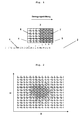
- multi-nozzles are preferably used, for example piezo-DoD (drop on demand) multi-nozzle high-temperature print heads whose nozzles can be controlled individually ( Fig. 1 ).
- Such printheads are eg in Menzel et al., MEMS Solutions for Precision Micro-Fluidic Dispensing Application, NIP20: International Conference on Digital Printing Technologies, Salt Lake City, UT, October 2004, Volume 20, pages 169-175 described.
- Drop shape and number can be controlled by various control parameters, such as temperature, voltage, pulse response and frequency.
- the frequency of the droplet generation is coupled directly to the feed rate of the printhead (s), so that by the juxtaposition of many individual droplets a closed layer structure is achieved ( Fig. 2 ).
- the drop volume is 90 pl, for example, with a nozzle diameter of 50 ⁇ m and a 36% by volume wax-based ZrO 2 ink. Due to the drop volume and its specific properties, such as surface tension, wetting behavior, viscosity and polymerization behavior, this results in the forming height of the crouched and solidified droplet and thus ultimately the layer thickness of the single layer.
- the layer thickness of the single layer can be varied by superimposed printing of the individual drops and is approximately 15-30 ⁇ m in the above example.
- the efficiency of the printing process can be further increased.
- the resolution at this For example, the method is 500 dpi, the position accuracy is ⁇ 50 ⁇ m, with a repeat accuracy of ⁇ 30 ⁇ m.
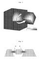
- FIG. 3 shows a cubic shaped body with a spherical core of the material A, which discretely merges into the material B towards the edge of the cube. Both the geometry and the spatial extent of the core material can be defined in advance.
- a printer with several print heads is preferably used.
- the printer preferably has at least two printheads, each fed from different reservoirs, so that two or more different slips can be printed.
- These printheads preferably each have a plurality of nozzles, i. These are so-called multi-nozzle or multi-nozzle printing heads. More preferably, the printer has from 3 to 20, and most preferably from 6 to 10, printing heads which are fed individually or in groups from different reservoirs (e.g., two print heads are fed from reservoir A, and two more print heads are fed from reservoir B).
- Support materials are here materials, in particular to support Undercuts and overhanging the printed body serve. Suitable support materials are, in particular, the binders and waxes used for the preparation of the slip.
- the support materials do not contain ceramic fillers, but may contain non-reinforcing inorganic fillers such as chalk, talc, which facilitate mechanical removal of the support structure.
- the printing of the support material is preferably carried out with one or two further printheads, for example, from the reservoir C are charged.
- the reservoirs A and B are each ceramic slip, which differ in their composition (eg reservoir A filled with ink A, reservoir B includes ink B).
- a targeted control of the print heads of the respective reservoirs A and B a two-dimensional layer is printed (s. Fig. 1 ) whose chemical composition varies over the extent of the layer (s. Fig. 2 ). Areas that are voids in the sintered body e Also, multi-nozzle or multi-nozzle print heads are preferred. are printed with the support material.
- the non-sintered body obtained by layered construction is called green body or green compact.
- a green compact is produced by mixing two or more slurries e.g. formed in an inkjet printing process to the desired geometric shape.
- the green compact is built up by the generation of single drops.
- the hardening of the generated drops from particle-filled inks or from support material preferably takes place by changing the temperature and in particular by free-radical polymerization, especially preferred by photopolymerization.
- the curing can be done in layers.
- each generated drop is cured immediately after its impact on the building platform or the previous layer and thus fixed in its position and extent.
- Wax-containing slip are hardened by cooling and polymerization, wax-free slip exclusively by polymerization.
- the exposure of the generated drops or layers preferably takes place parallel to the printing process, for example by light sources arranged laterally to the print heads, for example by UV or blue-light lamps.
- the exposure is carried out with light in the wavelength range of 200-550 nm, preferably with a light output of at least 500 mW / cm 2 .
- Slips with a content of ceramic particles (A) of more than 30% by volume are particularly preferred according to the invention.
- slip compositions of different composition are understood to mean slip whose different composition can be detected after debinding and sintering in the molding.
- slips which differ, for example, only in the composition of the binder removable during binder removal (B), are not different composite slips in the sense of the invention.
- the use of two or more slips is preferred, which differ in the composition of the ceramic particles.
- the ceramic particles contain different ceramics (slip A contains particles of ceramic A, slip B particles of ceramic B, etc.) and / or mixtures of ceramic particles of different composition (slip A contains, for example, 30% particles of the ceramic A and 70% particles of ceramic B, slip B contains 70% of particles of ceramic A and 30% of particles of ceramic B or slip A contains particles of ceramic A and slip B contains a mixture of particles of ceramic A and particles of ceramic B; etc.).
- the ceramics may differ simultaneously in their chemical composition, color, translucency, mechanical properties or in several parameters.
- a different composition of ceramic particles is also given if they are colored differently.
- the different colorations of the ceramic particles of the slips used are achieved in that the particles are coated with coloring components, as described below.
- a different composition of the slips used according to the invention can also be achieved with otherwise identical composition by adding different coloring components to the slips.
- coloring components are described in paragraph [0062] of EP 2 151 214 A1 and in paragraph [0043] of EP 2 233 449 A1 described.
- the coloring component transition metal compounds are acetylacetonates or carboxylic acid salts of the elements iron, cerium, praseodymium, terbium, lanthanum, tungsten, osmium, terbium and manganese.
- the salts of the carboxylic acids are preferably acetic, propionic, butyric, 2-ethylhexylcarbonic, stearic and palmitic acid.
- the corresponding Fe, Pr, Mn and Tb compounds e.g.
- the coloring component is preferably used in an amount of 0.00001 to 2.0% by weight, more preferably 0.001 to 1.0% by weight, and most preferably 0.01 to 0.5% by weight on the total mass of the ceramic particles (A).
- the coloring components are preferably applied to the ceramic particles.
- the method according to EP 1 859 757 A2 is the method according to EP 1 859 757 A2 , In this process, the colorant is applied in a fluidized bed reactor to an undyed oxide ceramic powder.
- the colorants used may preferably be aqueous solutions of the salts described above. Preference is given to water-soluble salts of d and f elements of the Periodic Table. Particularly preferred are nitrate or chloride hydrates. Examples of salts which can be used are Pr (NO 3 ) 3 -5H 2 O, Fe (NO 3 ) 3 .9H 2 O or Tb (NO 3 ) 3 .5H 2 O.
- the oxide ceramic powders coated with the coloring substances are then preferably classified, eg sieved with sieves with a mesh size of ⁇ 90 ⁇ m. This is especially done when there is too much agglomeration of the powder.
- the particles colored in the fluidized bed can be precalcined before they are made into an ink.
- the calcination of the particles takes place at temperatures of 100 to 600 ° C., preferably at 200 to 550 ° C., more preferably at 300 to 500 ° C. for a time of 1 to 10 h, preferably for 2 to h, particularly preferably for 2 to 4 h.
- Particles of glasses and glass ceramics can be colored according to the prior art with oxides of the transition elements.
- Component (A) of the slips used according to the invention are ceramic particles, "ceramic particles” being understood as meaning oxide ceramic particles and glass ceramic particles but also glass particles, preferably oxide ceramic or glass ceramic particles and mixtures of glass ceramic and glass particles.
- Oxide ceramics are solid, polycrystalline, silicic acid-free materials of oxides or oxide compounds, preferably from metal oxide such as ZrO 2 and / or Al 2 O 3 , which can be sintered without decomposition.
- Glass-ceramics are polycrystalline solids which, in addition to one or more crystalline phases, additionally contain glass-phase fractions. Glass ceramics are formed from glasses by controlled crystallization. Preference is given to lucite, apatite or lithium disilicate-containing glass ceramics. As the glass powder, particles of such glasses are preferred, which can be converted by crystallization into glass ceramics. For this, the glasses must contain imperative crystallization seeds. The crystallization can be triggered by debinding, sintering or a separate temperature treatment.
- the oxide ceramic particles used as component (A) are preferably oxide ceramic particles based on ZrO 2 and / or Al 2 O 3 , for example oxide particles of ZrO 2 , Al 2 O 3 or ZrO 2 -Al 2 O 3 , or oxide particles ZrO 2 or ZrO 2 -Al 2 O 3 stabilized with Y 2 O 3 or MgO.
- stabilized oxide ceramics which contain a stabilizing agent in addition to the base oxide ZrO 2 .
- a stabilizing agent preferably Y 2 O 3 , CeO 2 or mixtures of both Satbilmaschinesstoff be used.
- Y 2 O 3 is usually used here in the concentration up to 5 mol.%.
- dopings of up to 12 mol% are customary, based on the mass of the stabilized ceramic.
- ZrO 2 ceramics are referred to as Y-TZP (Yttrium Stabilized Tetragonal Zirconium Dioxide Polycrystals) and Ce-TZP (Cerium Stabilized Tetragonal Zirconium Dioxide Polycrystals).
- Y-TZP can be further increased by the addition of Al 2 O 3 .
- Such ceramics are referred to as AZT (alumina toughened zirconia).
- a preferred ATZ contains 80 wt .-% Y-TZP and 20 wt .-% Al 2 O 3 and has a mechanical bending strength of 2,000 MPa.
- oxide ceramics which consist exclusively of the substances mentioned.
- dental restorations In the manufacture of dental restorations on the one hand a high mechanical strength is desired, for example in the manufacture of bridges, on the other hand, dental restorations should have the most natural appearance possible. Both properties can not usually be realized optimally with a single material. However, any combination of different materials to optimize these properties is also not possible because e.g. different thermal expansion coefficients to thermomechanical stresses and different sintering temperatures can lead to an undesirably high porosity.
- the base slurry preferably contains exclusively as ceramic particles Y-TZP particles. It is also possible to use a plurality of differently colored base slips in this process, in which case the use of slips containing different colored Y-TZP particles is preferred.
- the secondary slurry preferably contains particles of a ceramic which contain 20 to 100% by weight Al 2 O 3 and 0 to 80% by weight Y-TZP, preferably 40 to 60 wt .-% Al 2 O 3 and 60 to 40 wt .-% Y-TZP, particularly preferably 20 wt .-% Al 2 O 3 and 80 wt .-% Y-TZP contains.
- Preference is given to slip containing exclusively particles of Al 2 O 3 or Al 2 O 3 and Y-TZP. It is possible to use a plurality of differently colored secondary slips, the use of slips containing different colored Al 2 O 3 and / or Y-TZP particles being preferred here as well.
- a local reinforcement of ceramic moldings is of great importance, for example, in the production of all-ceramic bridge frameworks.
- a targeted reinforcement of a ceramic bridge framework, for example of Y-TZP, in mechanically stressed linkage region, as in Fig. 4 shown schematically, is advantageous by the use of eg ATZ possible because the thermal expansion coefficients of the two ceramics (Y-TZP and ATZ ceramic) do not differ significantly from each other. In contrast, the more translucent Y-TZP is used in aesthetically important areas (copings and pontics).
- ATZ alumina toughened zirconia
- Y-TZP alumina toughened zirconia
- Al 2 O 3 alumina toughened zirconia
- this can be achieved by printing base slip and secondary slip in such a way that a ratio of 20% by weight Al 2 O 3 and 80% by weight Y-TZP is achieved in the regions to be reinforced.
- the mixing ratio can be adjusted during the printing process. It can be achieved by the use of slips containing 100 wt .-% Y-TZP or 100 wt .-% Al 2 O 3 , in each case based on the ceramic content of the slip, or by slips, for example, 100 wt.
- the areas to be reinforced are formed by printing the secondary slip alone.
- This variant is preferred according to the invention.
- the transition from the reinforced connecting bridge region (ATZ ceramic) to the translucent coping is preferably made gradually, in order to achieve a smooth transition between the two materials and thus to achieve a homogeneous ceramic structure.
- targeted color graduations can be implemented in the production of oxide ceramic dentures.
- several differently colored slip are used in the method described above.
- color grading it is preferable to use 2 or more, more preferably 2 to 10, and most preferably 3 to 6 differently colored slip.
- natural teeth differ not only in color, color intensity and brightness but also in translucency, it is advantageous for the production of natural-looking, tooth-colored, all-ceramic dental restorations to use more than two slips to build up the gradient, the number of which ultimately ends up being the tooth color and depend on the aesthetic requirement of the dental restoration.
- For the construction of color graded dental restorations with high mechanical strength preferably inks based on colored ZrO 2 or Y-TZP particles are used.
- Dental restorations with particularly natural color gradients can be produced if glass-ceramic particles or a mixture of glass and glass-ceramic particles is used as component (A). Particularly preferred are leucite, apatite and / or lithium disilicate glass ceramic particles.
- the color graduation is preferably carried out by printing 2 or more, more preferably 2 to 10 and most preferably 3 to 6 inks with differently colored Particles. In this case, the areas of the restoration in marginal and central areas are made up of intensely colored and cloudy particles, while in the incisal and peripheral areas less colored and less cloudy particles are used, similar to the natural course of the tooth color.
- the ceramic particles should be significantly smaller than the average diameter of the nozzle of the print head of the inkjet printer used to print the slurry.
- so-called submicron powders are preferably used in the slurry according to the invention, i. Ceramic particles with a maximum particle size of less than or equal to 5 ⁇ m, in particular less than or equal to 1 ⁇ m.
- the particles have a size of 0.01 to 5 .mu.m, more preferably from 0.1 to 1 .mu.m, and most preferably from 0.3 to 0.6 .mu.m.
- particle size is meant the actual size of the ceramic particles as they are in the slurry. Typically, this is the primary particle size, since any agglomerates present in the ceramic powder are largely decomposed into primary particles during the production of the slurry. However, agglomerates of ceramic primary particles may also be present in the slurry as long as they are sufficiently small to be printable with the desired inkjet nozzles, i. in preferred embodiments, the agglomerates as a whole satisfy the above particle size conditions.
- the size of the primary particles used as component (A) is preferably in the range of 50 to 500 nm, more preferably 75 to 200 nm; in the case of Y-TZP in the range of 50 and 500 nm, very preferably between 50 and 350 nm.
- the glass / glass ceramic particles used have a Primary particle size of 0.1 to 10 .mu.m, more preferably from 0.5 to 5 .mu.m.
- the primary particle sizes are the absolute upper and lower limits.
- the ceramic particles are preferably approximately spherical. It is also advantageous if the particles are present in non-agglomerated form, for example wholly or predominantly in the form of primary particles.
- Free-radically polymerizable monomers or mixtures thereof are preferred as free-radically polymerizable binders (component B) of the slip used according to the invention.
- the monomer is liquid at 20 ° C.
- the melting point is preferably below 0 ° C.
- the monomer is homogeneous, ie without phase separation, miscible with the optional wax (C).
- the monomer should not degrade at the processing temperature, such as the temperature described later in inkjet printing.
- the monomer has a large nonpolar radical, eg, a C 8 to C 20 radical.
- monomers are used in the slip having one or more, eg, two, (meth) acryloyl groups, with monomers having (meth) acryloyloxy groups being preferred.
- suitable radically polymerizable monomers are (meth) acrylates and di (meth) acrylates having a chain length of the alcohol residue of C 8 to C 18 , such as octadecyl acrylate; poly (meth) acrylated glycols, in particular poly (meth) acrylated propylene glycols; multiply (meth) acrylated short- to medium-chain polypropylene glycols with a preferred Mw of 200-2000, more preferably 300-1000, such as dipropylene glycol and Polypropylenglykoldiacrylate, for example, polypropylene glycol 400 diacrylate; Pentaerythritol di (meth) acrylate monocarboxylates having a chain length of C 8 to C 18 , such as pentaery
- component (B) is a mixture of octadecyl acrylate and pentaerythritol diacrylate monostearate.
- the optional component (C) of the slip used according to the invention is a wax.
- the term "wax” is to be understood as defined by the German Society for Fat Science in the DGF unit method MI 1 (75). Since the chemical composition and origin of various waxes is very different, waxes are defined only by their mechanical-physical properties.
- a substance is referred to as a wax, if it kneadable at 20 ° C, solid to brittle hard, has a coarse to fine crystalline structure, color is translucent to opaque, but not glassy; melts above 40 ° C without decomposition, is already slightly above the melting point slightly liquid (low viscosity) and not stringy; has a strong temperature-dependent consistency and solubility, and is polishable under light pressure.
- waxes between 40 and 130 ° C go into the molten state; Waxes are usually insoluble in water.
- waxes for use in the slip of the present invention have a melting point in the range of from 40 to less than 80 ° C, more preferably from 45 to 65 ° C, and most preferably from 54 to 56 ° C.
- Preferred waxes have at 80 ° C and a shear rate of 1000 s -1, a viscosity of ⁇ 10 mPa ⁇ s, in particular from 5 to 10 mPa ⁇ s and particularly preferably from 3 to 4 mPa ⁇ s.
- waxes are divided into three main groups: natural waxes, whereby here again between plant and animal waxes, mineral waxes and petrochemicals Waxing is differentiated; chemically modified waxes and synthetic waxes.
- the wax used as component (C) in the slip according to the invention can consist of one type of wax or else mixtures of different types of wax.
- petrochemical waxes such as paraffin wax (hard paraffin), petrolatum, microwax (microparaffin) and mixtures thereof, particularly preferably paraffin wax, are preferably used.
- Paraffin waxes which are commercially available as injection-molding binders for the production of oxide-ceramic and non-oxide-ceramic components in the hot-casting process (low-pressure injection molding), for example, are very suitable.
- commercially available waxes already contain emulsifiers and / or other rheology adjustment components.
- vegetable waxes e.g. Candelilla wax, carnauba wax, japan wax, esparto wax, cork wax, guaruma wax, rice germ oil wax, sugarcane wax, ouricury wax, montan wax; animal waxes, e.g. Beeswax, shellac wax, spermaceti, lanolin (wool wax), cudgel fat; Mineral waxes, e.g. Ceresin, ozokerite (earthwax); chemically modified waxes, e.g. Montan ester waxes, Sasol waxes, hydrogenated jojoba waxes, or synthetic waxes, e.g. Polyalkylene waxes, polyethylene glycol waxes are used.
- vegetable waxes e.g. Candelilla wax, carnauba wax, japan wax, esparto wax, cork wax, guaruma wax, rice germ oil wax, sugarcane wax, ouricury
- emulsifiers can be used; in a particularly preferred composition, glycerides of fatty acids and in particular polypropylene glycols are used.
- the polypropylene glycols preferably have a chain length of from 100 to 1000, particularly preferably from 100 to 600, very particularly preferably from 200 to 400.
- the emulsifier D is preferably used in an amount of 0.5 to 10 vol .-%, most preferably 1 to 5 vol .-%, in each case based on the total mass of the slurry.
- the slip as component (E) contain a polymerization initiator.
- Suitable polymerization initiators are free-radical polymerization initiators, especially photoinitiators.
- the known radical photoinitiators for the visible range cf. JP Fouassier, JF Rabek (ed.), Radiation Curing in Polymer Science and Technology, Vol. II, Elsevier Applied Science, London and New York 1993 ), such as acyl-bisacylphosphine oxides, preferably ⁇ -diketones such as 9,10-phenanthrenequinone, diacetyl, furil, anisil, 4,4'-dichlorobenzil and 4,4'-dialkoxybenzil and camphorquinone.
- ⁇ -diketones are preferably used in combination with aromatic amines.
- Redox systems which have proven particularly useful are combinations of camphorquinone with amines, such as N, N-dimethyl-p-toluidine, N, N-dihydroxyethyl-p-toluidine, 4-dimethylaminobenzoic acid ethyl ester or structurally related systems.
- Particularly preferred photoinitiators are Norrish type I photoinitiators, especially monoacyl trialkyl or diacyl dialkyl germanium compounds, e.g. Benzoyltrimethylgermanium, Dibenzoyldiethylgermanium or bis (4-methoxybenzoyl) diethylgermanium. It is also possible to use mixtures of the various photoinitiators, such as e.g. Dibenzoyldiethylgermanium in combination with camphorquinone and 4-Dimethylaminobenzoeklathylester.
- the polymerization initiator (E) is more particularly used in an amount of 0.001 to 3.0% by volume, preferably 0.01 to 1% by volume preferably used from 0.05 to 0.8 vol .-%, in each case based on the total mass of the slurry.
- the slip may optionally contain other additives (F), such as stabilizers (inhibitors), dispersing agents, melt viscosity reducing substances (rheology adjustment component) and combinations thereof. These are added in an amount of 0.01 to 5% by volume to the slips.
- F additives
- the stabilizers improve the storage stability of the slip and also prevent an uncontrolled polyreaction.
- the inhibitors are preferably added in such an amount that the slips are storage stable over a period of about 2 to 3 years.
- suitable inhibitors include the 2,2,6,6-tetramethyl-piperindin-1-oxyl radical (TEMPO), phenothiazine, iodine and Cupfer (I) iodide.
- the inhibitors are used in an amount of 5 to 500 wt ppm, more preferably 50 to 200 ppm by weight, in each case based on the total mass of the monomer (s).
- the inhibitors are preferably used in an amount of 0.03 to 3% by volume, preferably 0.3 to 1.2% by volume.
- dispersing agents it is possible to use all customary dispersing aids for dispersing oxidic particles in a non-polar medium.
- suitable dispersing aids include a polar "anchor group" that can be attached to the particle surface, and a nonpolar, particulate-repellent group that effects maximum steric stabilization of the suspension.
- Preferred dispersants are polyester-based dispersing aids, such as. B. Hypermer LP-1 from Uniqema, GB.
- the dispersing aid is preferably used in an amount of 0.1 used to 5 wt .-%, preferably 0.5 to 2 wt .-% and in particular 1.1 to 1.5 wt .-%, in each case based on the total mass of ceramic particles.
- Based on the total composition of the slip dispersing aids are preferably used in an amount of 0.3 to 16 vol .-%, preferably 1.6 to 6.4 vol .-% and in particular 2.0 to 4.8 vol .-%.
- the total amount of component (s) (F) is preferably from 0.1 to 15% by volume, more preferably from 0.1 to 10% by volume, very preferably from 0.5 to 9% by weight and in particular 1, 5 to 5 vol .-% based on the total composition of the slip.
- a melt viscosity-lowering substance may be added to the slurry of the present invention to lower its viscosity in the liquid state.
- longer chain (C 8 -C 20 ) low melting point olefins which are solid at room temperature, such as hexadecene and octadecene, are suitable for this purpose.
- waxy slurries at 20 ° C have a pasty to solid consistency. So a sedimentation of the ceramic particles is avoided and ensures a long shelf life.
- 80 ° C and a shear rate of 1000 s -1 it preferably has a viscosity of ⁇ 200 mPa ⁇ s, particularly preferably ⁇ 100 mPa ⁇ s.
- the slip according to the invention can preferably be printed at the appropriate temperature with an inkjet printer which has a print head nozzle with a diameter of about 100 ⁇ m.
- the slip can be prepared by dispersing the ceramic particles in the binder, eg, a mixture of wax, monomers, and optional additives.
- the dispersion is preferably carried out at a temperature at which the wax and preferably also the monomers are liquid, preferably at 70 to 110 ° C.
- the dispersion is carried out using high shear rates, for example at 500 to 5,000 s -1 .
- the filler may, for example, using a dissolver (eg Dispermat® Fa. VMA Getzmann GmbH, Reichshof, DE) at speeds of up to 3,000 / min, and preferably at elevated temperature of 70 to 110 ° C in the mixture be dispersed from wax, monomers and optional additives.
- a dissolver eg Dispermat® Fa. VMA Getzmann GmbH, Reichshof, DE
- agglomerates of the preferred ceramic powders are largely decomposed into the primary particles. If the viscosity in the liquid slurry should be too high, it is reduced by the addition of viscosity-reducing substances to values of preferably ⁇ 200 mPa ⁇ s, more preferably ⁇ 100 mPa ⁇ s, measured at a shear rate of 1000 s -1 and a temperature of 80 ° C.
- the wax-free inks differ from waxy in that they do not solidify by cooling to room temperature and thus are liquid at room temperature.
- the preparation can be carried out, for example, at temperatures of 40 to 60 ° C using a dissolver (eg Dispermat® Fa. VMA Getzmann GmbH, Reichshof, D) at speeds of up to 3,000 / min.
- the inks preferably have a viscosity of ⁇ 5,000 mPas and in particular of ⁇ 500 mPa ⁇ s at room temperature; when the temperature is raised to 40 to 90 ° C., they are preferably lowered to ⁇ 200 mPa ⁇ s, measured at a shear rate of 1000 s -1 .
- the ceramic particles are first mixed in a Turbular mixer (eg type T2C from Willy A. Bachhofen AG Maschinenfabrik, Muttenz, CH) and this mixture is then processed in the dissolver under the conditions listed above to achieve an effective deagglomeration of the particles.
- a Turbular mixer eg type T2C from Willy A. Bachhofen AG Maschinenfabrik, Muttenz, CH
- the homogenized mixture in a further mixing and homogenization step with the components B and optionally C to F diluted to the solid content required for printing and processed with the dissolver or other mixing apparatus to a homogeneous mixture, for example by mixing for 10 minutes at speeds of up to 3000 / min in SpeedMixer DAC400FVZ (Hauschild & Co.) Co KG, Hamm, D).
- Wax-containing slip are preferably at a temperature in the range of 60 ° C to 140 ° C, more preferably from 70 ° C to 120 ° C and most preferably from 80 ° C to 100 ° C, thereby meaning the temperature in the pressure nozzle meant is.
- the temperature of the building platform in this case is preferably in the temperature range from 20 ° C to 100 ° C, more preferably from 20 ° C to 70 ° C, most preferably from 20 ° C to 40 ° C. Due to the temperature difference between the pressure temperature and the temperature of the platform, the curing process can be controlled.
- each layer is cured by polymerization and solidified throughout the volume by the resulting polymer network of moldings.
- the curing by polymerization can be carried out in layers or preferably parallel to the printing.
- each drop is cured immediately after printing, for example by irradiation with light.
- Wax-free slips are preferably printed at a temperature in the range of from 40 ° C to 140 ° C, more preferably from 50 ° C to 120 ° C, and most preferably from 60 ° C to 110 ° C.
- each drop is cured by polymerization.
- the curing can be carried out in layers.
- the temperature of the construction platform in this case is preferably in the range from 20 ° C to 100 ° C, more preferably from 20 ° C to 70 ° C, most preferably from 20 ° C to 40 ° C.
- the support material is removed mechanically or chemically.
- the shaped bodies are then chemically and / or thermally debinded and finally sintered.
- Debindering (d) serves to remove the temporary binder and, if present, waxes and additives from the green body. Particularly preferably, the removal of the support material takes place together with the debindering of the green body. Due to the debindering, the greenling becomes the Weissling.
- Support material and binder may preferably be removed thermally, for example by melting, evaporation or combustion processes.
- the green compact is preferably heated to a temperature of 50 ° C to 600 ° C, more preferably from 60 ° C to 500 ° C and most preferably from 150 ° C to 500 ° C. The heating is preferably carried out for a period of from 3 hours to 7 hours.
- the obtained white compact is sintered in step (e) to form a dense ceramic shaped body.
- the sintering of the white pieces of Y-TZP and ATZ ceramics takes place in the sintering furnace, preferably at temperatures between 1200 ° C and 1700 ° C, preferably between 1300 ° C and 1600 ° C, more preferably between 1350 ° C and 1500 ° C.
- Whitings of glass or glass ceramic powders are preferably at temperatures in the range of 500 ° C and 1200 ° C, more preferably between 600 ° C and 1000 ° C, more preferably between 700 ° C and 900 ° C.
- the sintering time is preferably 2 hours to 6 hours, more preferably in 4 hours to 5.5 hours.
- Sintering (e) is a high-temperature process that serves to solidify the molded body as free of pores as possible. Material transfer and grain growth processes take place here (in the case of oxide ceramics, predominantly by diffusion), through which the individual ceramic particles "move” towards one another and form a dense, firm and pore-free structure.
- the sintering process leads to a densification of preferably> 98%, preferably> 98.5% and very particularly preferably> 99% of the theoretical density of the ceramic.
- the debinding and sintering takes place in a one-step process in the temperature range between 20 ° C and 1700 ° C, preferably between 20 ° C and 1600 ° C, more preferably between 20 ° C and 1500 ° C.
- the duration of the one-stage thermal process amounts to 2 hours to 12 hours, preferably to 4 hours to 10 hours, particularly preferably to 6 hours to 10 hours.
- the shaped body undergoes a volumetric shrinkage, which varies depending on the degree of filling.
- This volume shrinkage is taken into account in advance by overdimensioning the molded body to be printed, in order to ensure the accuracy of fit of the debindered and sintered component.
- the drop volume specifies the smallest voxel size that can be generated.
- the 3D ink-jet printing method of ceramic slips according to the invention makes it possible to use a plurality of print heads, which are fed from reservoirs filled with differently composed, ie, for example, differently colored slips, the production of individualized, three-dimensionally material- and / or color-graded ceramic green bodies, which can then be densely sintered to form ceramic bodies.
- the inventive method is suitable for the production of any ceramic moldings.
- a preferred application of the method is the production of dental restorations, such as bridges, in particular bridge frameworks, inlays, onlays, crowns, implants, abutments and veneers.
- the use of this method with a colored graduation allows the dental technician or dentist to produce the individual color design of the denture by means of an automated production.
- the virtually constructed dental frameworks are milled or ground from prefabricated blanks.
- These prefabricated blanks consist of 100% of a material, usually of partially sintered Y-TZP.
- This Y-TZP has a breaking strength of over 900 MPa in the sintered state. Due to these mechanical properties, the minimum wall thicknesses and thicknesses required by the material suppliers are given, which are taken into account in the automated production of dentures via the milling technology.
- a "connector” applies the connecting bridge between crowns and / or bridge members in bridges with more than two elements, such as at 8 and 9 in Figure 4 you can see.
- the method according to the invention makes it possible for the first time to produce dental restorations in an economical manner, which satisfy both aesthetically and mechanically.
- the method according to the invention also comprises blending the sintered shaped body, For example, a backbone for a dental bridge, preferably with a glass ceramic veneering.
- the veneering is done using the classical methods such as manual coating, overpressing or CAD / CAM methods as in DE 10 2005 023 105 and DE 10 2005 023 106 described.
- the veneer is produced as a separate shaped body in the manner described above using a slip containing as component (A) glass ceramic particles.
- the veneer is debinded after printing, sintered and then connected to the scaffold to be veneered, for example glued.
- the high mechanical strength of an oxide ceramic which is preferably used for the preparation of the skeleton, with the excellent optical properties of a glass ceramic, which is preferably used for the veneering combine.
- the simultaneous printing of oxide and glass ceramic is not preferred according to the invention, since the sintering of such mixtures leads to unsatisfactory results.
- ATZ ceramics have a lower translucency compared to the Y-TZP, so that such ceramics are less preferred for the anterior region for aesthetic reasons.
- a model of the spatial distribution of the two or more slips in the molded article is prepared, and then the two or more slips are output in the space-distributed manner at each point (x, y, z) of the space.
- This model can be a three-dimensional computer model, ie a dataset or an image, whereby each point (x, y, z) or each voxel a particular composition of one or more slips is assigned.
- This data set or this image is used to control the method according to the invention, ie the shaped body is generated computer-controlled on the basis of a three-dimensional computer model of the shaped body, for example.
- the oral situation is first of all digitally recorded on the basis of a scan on a gypsum model or by means of an interoral scan.
- a master model is preferably also produced by means of an automated production technology (by milling, stereolithography, or ink-jet printing) in order to check the fit.
- the bridge framework to be created is constructed using CAD software. The construction of the bridge framework is carried out according to the material-specific requirements with regard to the numerical compensation of the sintering shrinkage, the minimum wall thickness and connector thicknesses.
- the output format of the constructed bridge framework is a file format to which additional attributes such as color information can be assigned (eg IGES format, Nurbs).
- This is "sliced” before it is sent to the printer, ie the three-dimensional virtual design is "sliced” into slices.
- the height of the respective disc corresponds to the layer height during the build-up or printing process, the lateral extent corresponding to the respective lateral extensions of the constructed component in the respective position in the z-direction.
- the bridge is now built up in layers by successive printing of the individual layers (slices). The thus obtained green body is then debinded and sintered as described.
- Wax-free slip composition Wax-free slip composition
- Wt .-% Y-TZP 1 25.82% by volume 61.59% by weight Al 2 O 3 2) 8.18 vol.% 12.76% by weight Disperbyk 111 11) 3.44% by volume 1.21% by weight PPG200 12) 22.18 Vol .-% 8.69% by weight octadecene 1,90 Vol.
- Ink A from Example 1 was printed under the following parameters in Piezo-DoD multi-nozzle printing heads (E1 GEN3, Ricoh, Simi Valley, California, USA):
- the green body was then debinded and sintered under the following conditions:
- debindering and sintering were carried out in one process step under the following conditions:
Abstract
Description
Die vorliegende Erfindung betrifft ein Verfahren zur Herstellung von Keramikformteilen und insbesondere von Dentalrestaurationen durch dreidimensionales Drucken.The present invention relates to a method for the production of ceramic moldings and in particular of dental restorations by three-dimensional printing.
Zur Herstellung von Formkörpern werden in zunehmendem Maße sogenannte "aufbauende Verfahren" eingesetzt. Als Synonym für diese "aufbauenden" Möglichkeiten wird oftmals der Begriff "Generative Fertigungsverfahren" verwendet. Unter diesen Begriffen werden verschiedene generative Fertigungsverfahren zusammengefasst, bei denen aus computergestützten Konstruktionsdaten (CAD-Daten) 3-dimensionale Modelle oder Bauteile hergestellt werden (
Derzeit sind hauptsächlich zwei unterschiedliche Methoden des Inkjet-Druckens zur Herstellung dreidimensionaler Körper in Gebrauch. Bei der ersten Methode wird eine Bindemittellösung auf eine Pulverbettschicht gedruckt. Dieser Binder "verklebt" die Pulverpartikel und fixiert sie so an Ort und Stelle. Durch erneutes Auftragen einer weiteren Pulverschicht und erneutes Drucken des Binders in die Pulverschicht kann so schichtweise ein dreidimensionaler Körper generiert werden. Nach Abschluss des Druckprozesses wird der Formkörper aus der Pulverschüttung entnommen und vom überschüssigen Pulver gereinigt. Der generierte Formkörper kann sofort verwendet werden, sofern er z.B. aus Kunststoff hergestellt wurde. Besteht der Formkörper aus keramischen Partikeln und soll er abschliessend ein dichtes keramisches Bauteil ergeben, so muss noch ein thermischer Prozessschritt erfolgen, in dem der Formkörper entbindert und dicht gesintert wird. Beim Entbindern werden die organischen Bindemittel pyrolysiert. Die Prozessparameter der Entbinderung und Sinterung richten sich hierbei u.a. nach Art und Anteil des Bindemittels und nach dem keramischen Werkstoff. Häufig ist eine abschliessende Oberflächenhandlung, wie z.B. Polieren oder Glasieren, erforderlich.Currently, there are mainly two different methods of inkjet printing for making three-dimensional bodies in use. In the first method, a binder solution is printed on a powder bed layer. This binder "sticks" the powder particles and fixes them in place. By re-applying a further powder layer and re-printing the binder in the powder layer, a three-dimensional body can be generated in layers. After completion of the printing process, the shaped body is removed from the powder bed and cleaned of excess powder. The generated Shaped body can be used immediately, if it was made of plastic, for example. If the shaped body consists of ceramic particles and if it should finally result in a dense ceramic component, then a thermal process step must still take place in which the shaped body is debinded and densely sintered. During debinding, the organic binders are pyrolyzed. The process parameters of binder removal and sintering depend, among other things, on the type and proportion of the binder and on the ceramic material. Often a final surface treatment, such as polishing or glazing, is required.
Die
Bei der zweiten Methode werden mit Feststoffpartikeln gefüllte Tinten verwendet und daraus dreidimensionale Körper direkt gedruckt. Bei dieser Methode wird keine Pulverschüttung benötigt. Der dreidimensionale Körper wird auch hier schichtweise aufgebaut, indem jeweils eine zweidimensionale Schicht (xy-Ebene) gedruckt und gehärtet wird. Die Härtung kann beispielsweise durch Polymerisation, Trocknung oder Verfestigung durch Abkühlung erfolgen. Simultan kann ein leicht entfernbares Stützmaterial verdruckt werden, welches das Drucken überhängender Bereiche ermöglicht. Durch wiederholtes Übereinanderdrucken (z-Richtung) von Schichten aus Modell- und gegebenenfalls Stützmaterial entsteht ein dreidimensionales Objekt. Nach Trennen des gedruckten Objektes von der Stützstruktur, beispielsweise durch selektives chemisches Lösen des Stützmaterials, liegt ein 3-D-Bauteil vor.The second method uses solid particles filled in inks and directly prints three-dimensional solids. In this method, no powder bed is needed. Here again, the three-dimensional body is built up in layers by printing and hardening a two-dimensional layer (xy plane). The curing can be carried out, for example, by polymerization, drying or solidification by cooling. Simultaneously, an easily removable backing material can be printed, which overhangs the printing Areas allows. Repeated overprinting (z-direction) of layers of model and possibly support material creates a three-dimensional object. After separating the printed object from the support structure, for example by selective chemical release of the support material, a 3-D component is present.
Die
Die
Die beschriebenen Verfahren ergeben Keramikformkörper, die aus einer Keramik homogen aufgebaut sind. Um das Aussehen des natürlichen Zahns möglichst wirklichkeitsgetreu nachzuahmen ist es jedoch erforderlich, unterschiedliche Materialien, die sich beispielsweise in Farbe und Transluzenz unterscheiden, miteinander zu kombinieren.The described methods yield ceramic shaped bodies, which are constructed homogeneously from a ceramic. To imitate the appearance of the natural tooth as realistically as possible, however, it is necessary to use different materials differ in color and translucency, for example, to combine with each other.
Die
Unter Gradientenwerkstoffe sind Werkstoffe zu verstehen, deren Zusammensetzung, Struktur und Gefüge sich graduell über das Volumen ändern, was mit entsprechenden Änderungen der Materialeigenschaften verbunden ist. Daraus ergibt sich die Möglichkeit, Materialien herzustellen, die an bestimmte Anwendungen angepasst sind. Gradientenwerkstoffe werden auch als gradierte Werkstoffe oder FGM (functionally graded material) bezeichnet.Gradient materials are to be understood as materials whose composition, structure and structure change gradually over the volume, which is associated with corresponding changes in the material properties. The result is the possibility to produce materials that are adapted to specific applications. Gradient materials are also referred to as graded materials or FGM (functionally graded material).
Gradierte Werkstoffe sind aufgrund ihrer besonderen physikalischen Eigenschaften in vielen Bereichen von hohem Interesse. In technischen Bereichen kann mit Hilfe funktionalisiert gradierter Formkörper ein gezieltes Werkstoffdesign realisiert werden, um speziellen Anforderungen im jeweiligen Einsatzbereich gerecht zu werden. Es wurden zahlreiche Bemühungen zur Herstellung gradierter Werkstoffe unternommen. Eine funktionalisierte Gradierung entsteht durch den gezielten Aufbau eines Werkstückes durch zwei oder mehrere Materialien. Die meistverwendeten Werkstoffpaarungen hierbei sind Keramik-Metall, Keramik-Keramik und Keramik-Glas.Graded materials are of great interest in many areas due to their special physical properties. In technical areas, a functional material design can be realized with the help of functionalized graded moldings to meet special requirements in the respective field of application. Numerous efforts have been made to produce graded materials. A functionalized grading is created by the targeted construction of a workpiece by two or more materials. The most commonly used material combinations here are ceramic-metal, ceramic-ceramic and ceramic-glass.
Die Herstellung von gradierten Formkörpern ist ein technisch sehr aufwendiger Prozess. Keines der beschriebenen Verfahren ist in jeder Hinsicht zufriedenstellend. In der Praxis werden gradierte Werkstücke zurzeit hauptsächlich über das Trockenpressverfahren hergestellt. Bei der Trockenpresstechnik muss die Pressmatrize stufenweise mit den unterschiedlichen Materialien gefüllt werden, und der Rohling wird axial verpresst und ggf. abschliessend kaltisostatisch nachverdichtet. Trockenverpresste gradierte Formkörper weisen nur eine zweidimensionale Gradierung auf, eine dreidimensionale Gradierung lässt sich mit diesem Verfahren praktisch nicht umsetzen. Die Bauteile sind aus mehreren Schichten unterschiedlicher Materialien aufgebaut und weisen somit eine schichtförmige Gradierung auf. Jede einzelne Schicht besteht dabei entweder aus jeweils gleichem Material oder aus einer für die jeweilige Schicht definierten Mischung unterschiedlicher Materialien. Andere Fertigungsverfahren, wie z.B. die Elektrophorese, Infiltrationstechniken, Plasmasprühverfahren oder oberflächliche Laserbehandlungen, befinden sich noch in der Erprobungsphase und sind momentan erst Gegenstand aktueller Untersuchungen. Dabei stehen vorrangig die Evaluierung der Möglichkeiten und Grenzen der gewählten Verfahren sowie die Charakterisierung der spezifischen Eigenschaften der so generierten Formkörper im Vordergrund. Diese Verfahren sind dem jetzigen Stand der Technik nur zum Aufbau von Gradientenwerkstoffen geeignet, deren Gradierung sich in einer Raumrichtung ändert.The production of graded moldings is a technically very complex process. None of the described methods is satisfactory in every respect. In practice, graded workpieces are currently produced mainly by the dry pressing process. In the dry press technique, the press die must be filled step by step with the different materials, and the blank is pressed axially and, if necessary, subsequently densified by cold isostatic pressing. Dry-pressed graded moldings have only a two-dimensional gradation, a three-dimensional grading can not practically implement this method. The components are constructed from several layers of different materials and thus have a layered gradation. Each individual layer consists either of the same material or of a mixture of different materials defined for each layer. Other manufacturing processes, such as electrophoresis, infiltration techniques, plasma spraying or superficial laser treatments, are still in the testing phase and are currently the subject of current investigations. Standing there Priority will be given to the evaluation of the possibilities and limits of the chosen methods as well as to the characterization of the specific properties of the shaped bodies thus generated. These methods are suitable in the current state of the art only for the construction of gradient materials whose gradation changes in a spatial direction.
Die Aufgabe der Erfindung besteht darin, die Nachteile des bekannten Standes der Technik zu überwinden und ein Verfahren zur Herstellung eines keramischen Formkörpers zur Verfügung zu stellen, das sich insbesondere zur Herstellung von Dentalrestaurationen eignet. Das Verfahren soll die gezielte, unabhängige Variation von Materialeigenschaften wie z.B. Farbe, Transluzenz und/oder mechanische Festigkeit in allen drei Raumrichtungen ermöglichen und dicht gesinterte Formkörper mit hoher Enddichte ergeben. Aufgabe der Erfindung ist insbesondere die Bereitstellung eines Verfahrens, das die Herstellung von Dentalrestaurationen mit hoher mechanischer Belastbarkeit und guten optische Eigenschaften, d.h. einem möglichst naturgetreuem Aussehen erlaubt.The object of the invention is to overcome the disadvantages of the known prior art and to provide a method for producing a ceramic shaped body which is particularly suitable for the production of dental restorations. The method is intended to provide the targeted, independent variation of material properties, e.g. Allow color, translucence and / or mechanical strength in all three spatial directions and dense sintered moldings with high final density. The object of the invention is, in particular, to provide a method which permits the production of dental restorations with high mechanical strength and good optical properties, i. allowed a natural look as possible.
Die Aufgabe wird erfindungsgemäß durch ein Inkjet-Druckverfahren zur generativen Herstellung von Formkörpern gelöst, bei dem man
- (a) Keramikschlicker schichtweise auf einen Träger aufbringt und härtet,
- (b) man auf die gehärtete Schicht eine weitere Schicht aufbringt und härtet,
- (c) man Schritt (b) so oft wiederholt, bis man einen Körper mit der gewünschten geometrischen Form hat,
- (d) man dann den Körper einer chemischen Behandlung oder einer Wärmebehandlung zur Entfernung des Bindemittels (Entbinderung) unterwirft, und
- (e) man den Körper aus Schritt (d) sintert.
- (a) applying ceramic slurry layer by layer to a carrier and curing,
- (b) applying another layer to the cured layer and curing,
- (c) repeating step (b) until one has a body of the desired geometric shape,
- (D) then subjecting the body to a chemical treatment or a heat treatment to remove the binder (debindering), and
- (e) sintering the body of step (d).
Das Verfahren ist dadurch gekennzeichnet, dass man mindestens zwei unterschiedlich zusammengesetzte Keramikschlicker zur Herstellung der Formkörper verwendet. Das Aufbringen der Keramikschlicker erfolgt dabei so, dass die relativen Anteile der Schlicker ortsabhängig gesteuert werden, so dass die aufgebrachten relativen Anteile der Schlicker innerhalb einer Schicht entlang wenigstens einer Richtung in der Schichtebene in vorgebbarer Weise variieren, wobei das Aufbringungsschema der Schlicker von Schicht zu Schicht variieren kann. Als Folge der Variation der Zusammensetzung können Formkörper hergestellt werden, deren Materialeigenschaften in drei Raumrichtungen (x,y,z) variieren. Solche Formkörper werden im Folgenden auch als gradierte Formkörper bezeichnet. Die Formkörper können neben Schichten mit variierender Zusammensetzung auch Schichten mit homogener Zusammensetzung enthalten, d.h. Schichten, die nur einen Keramikschlicker oder eine homogene Mischung unterschiedlicher Schlicker enthalten.The process is characterized in that at least two differently composed ceramic slips are used to produce the shaped bodies. The application of the ceramic slip takes place in such a way that the relative proportions of the slip are controlled in a location-dependent manner, so that the applied relative proportions of the slip vary within a layer along at least one direction in the layer plane in a predeterminable manner, the application scheme of the slip from layer to layer can vary. As a result of the variation of the composition, molded articles can be produced whose material properties vary in three spatial directions (x, y, z). Such shaped bodies are also referred to below as graded shaped bodies. In addition to layers of varying composition, the molded articles may also contain layers of homogeneous composition, i. Layers containing only a ceramic slurry or a homogeneous mixture of different slips.
Die Formulierung, dass die relativen Anteile der Schlicker innerhalb einer Schicht entlang wenigstens einer Richtung in der Schichtebene in vorgebbarer Weise variieren, umfasst auch Ausführungsformen, bei der diese Schicht neben entlang der wenigsten in einer Richtung variierenden Bereiche auch Bereiche mit konstanter Zusammensetzung enthält.The formulation that the relative proportions of the slips within a layer vary in a predeterminable manner along at least one direction in the layer plane also includes embodiments in which this layer also contains areas of constant composition along along the least in one direction varying areas.
Gegenstand der Erfindung sind auch die durch das erfindungsgemäße Verfahren hergestellten Formkörper.The invention also relates to the shaped bodies produced by the process according to the invention.
Die Keramikschlicker werden vorzugsweise durch ein Inkjet-Druckverfahren schichtweise aufgebracht, z.B. mit Hilfe eines sogenannten Inkjet-Druckers. Systeme aus einem Inkjet-Drucker, der zum Verdrucken von Keramikschlickern geeignet ist, und aus mindestens zwei unterschiedlichen Keramikschlickern bestehen, sind ebenfalls Gegenstand der Erfindung.The ceramic slip are preferably applied in layers by an inkjet printing process, for example by means of a so-called inkjet printer. Systems of an inkjet printer, which is suitable for the printing of ceramic slips, and consist of at least two different ceramic slips, are also the subject of the invention.
Bei den erfindungsgemäß verwendeten Schlickern handelt es sich um Suspensionen von keramischen Partikeln in einen Dispersionsmittel. Die Schlicker werden hierin auch als keramisch gefüllte Inkjet-Tinten oder einfach als Tinten bezeichnet.The slips used in the invention are suspensions of ceramic particles in a dispersant. The slurries are also referred to herein as ceramic-filled inkjet inks or simply inks.
Im 3D Ink-Jet Druckverfahren erfolgt eine gezielte Dosierung und Positionierung einzelner Tropfen aus keramisch gefüllten Tinten. In dem erfindungsgemäßen Verfahren werden vorzugsweise sogenannte Multi-Düsen verwendet, z.B. Piezo-DoD-(drop on demand) Multi-Düsen-Hochtemperaturdruckköpfe, deren Düsen einzeln angesteuert werden können (
Durch eine gesteuerte Positionsverschiebung des oder der Druckköpfe relativ zur Bauplattform (Träger) in den Raumrichtungen x und y und, nach Vervollständigung der jeweiligen x-y Ebene, in z-Richtung, wird während des Druckprozesses durch einen schichtweisen Aufbau ein dreidimensionaler Formkörper generiert. Variiert man z.B. die chemische Zusammensetzung der einzelnen aufeinander gedruckten Schichten, wird ein räumlicher Gradient in der chemischen Zusammensetzung erzeugt. Dies ist in
Erfindungsgemäß wird vorzugweise ein Drucker mit mehreren Druckköpfen eingesetzt. Der Drucker weist vorzugsweise mindestens zwei Druckköpfe auf, die jeweils aus unterschiedlichen Reservoiren gespeist werden, so dass zwei oder mehr unterschiedliche Schlicker verdruckt werden können. Diese Druckköpfe haben vorzugweise jeweils mehrere Düsen, d.h. es handelt sich um sogenannte Multi-Düsen- oder Multi-Nozzle-Druckköpfe. Besonders bevorzugt weist der Drucker 3 bis 20 und ganz besonders bevorzugt 6 bis 10 Drückköpfe auf, die einzeln oder gruppenweise aus unterschiedlichen Reservoiren beschickt werden (z.B. zwei Druckköpfe werden aus Reservoir A beschickt, zwei weitere Druckköpfe werden aus Reservoir B beschickt).According to the invention, a printer with several print heads is preferably used. The printer preferably has at least two printheads, each fed from different reservoirs, so that two or more different slips can be printed. These printheads preferably each have a plurality of nozzles, i. These are so-called multi-nozzle or multi-nozzle printing heads. More preferably, the printer has from 3 to 20, and most preferably from 6 to 10, printing heads which are fed individually or in groups from different reservoirs (e.g., two print heads are fed from reservoir A, and two more print heads are fed from reservoir B).
Zur Herstellung von gradierten Körpern wird vorzugsweise in den Schritten (a) und (b) zusammen mit dem Keramikschlicker oder im Anschluss an diese Schritte ein Stützmaterial aus einem separaten Druckkopf verdruckt. Stützmaterialien sind hierbei Materialien, die insbesondere zur Unterstützung von Unterschnitten und Überhängen der gedruckten Körper dienen. Als Stützmaterialien eignen sich insbesondere die zur Herstellung der Schlicker verwendeten Bindemittel und Wachse. Die Stützmaterialien enthalten keine keramischen Füllstoffe, können aber nicht verstärkende anorganische Füllstoffe, wie z.B. Kreide, Talk, enthalten die das mechanische entfernen der Stützstruktur erleichtern.To produce graded bodies, preferably in steps (a) and (b) together with the ceramic slurry or following these steps a support material is printed from a separate print head. Support materials are here materials, in particular to support Undercuts and overhanging the printed body serve. Suitable support materials are, in particular, the binders and waxes used for the preparation of the slip. The support materials do not contain ceramic fillers, but may contain non-reinforcing inorganic fillers such as chalk, talc, which facilitate mechanical removal of the support structure.
Das Verdrucken des Stützmaterials erfolgt vorzugweise mit einem oder zwei weitere Druckköpfen, die z.B. aus dem Reservoir C beschickt werden. In den Reservoiren A und B befinden sich jeweils Keramikschlicker, die sich in ihrer Zusammensetzung unterscheiden (z.B. Reservoir A gefüllt mit Tinte A, Reservoir B beinhaltet Tinte B). Durch eine gezielte Ansteuerung der Druckköpfe der jeweiligen Reservoire A und B wird eine zweidimensionale Schicht gedruckt (s.
Der durch schichtweisen Aufbau erhaltene, ungesinterte Körper wird als Grünkörper oder Grünling bezeichnet. Erfindungsgemäß wird ein Grünling hergestellt, indem man zwei oder mehr Schlicker z.B. in einem Inkjet-Druckverfahren zu der gewünschten geometrischen Form formt. Der Grünling wird hierbei durch die Generierung einzelner Tropfen aufgebaut. Ein Vorteil des erfindungsgemäßen Verfahren ist, dass die Zusammensetzung des Formkörpers durch Variation der verwendeten Schlicker punktgenau eingestellt werden kann.The non-sintered body obtained by layered construction is called green body or green compact. According to the invention, a green compact is produced by mixing two or more slurries e.g. formed in an inkjet printing process to the desired geometric shape. The green compact is built up by the generation of single drops. An advantage of the method according to the invention is that the composition of the shaped body can be set precisely by varying the slurry used.
Die Härtung der generierten Tropfen aus partikelgefüllten Tinten oder aus Stützmaterial erfolgt vorzugsweise durch Temperaturänderung und insbesondere durch radikalische Polymerisation, besonders bevorzugt durch Photopolymerisation. Die Härtung kann schichtweise erfolgen. Gemäß einer besonders bevorzugten Ausführungsform des erfindungsgemäßen Verfahrens wird jedoch jeder generierte Tropfen unmittelbar nach seinem Auftreffen auf der Bauplattform bzw. der vorhergehenden Schicht gehärtet und somit in seiner Position und Ausdehnung fixiert. Wachshaltige Schlicker werden hierbei durch Auskühlen und Polymerisation gehärtet, wachsfreie Schlicker ausschliesslich durch Polymerisation. Die Belichtung der generierten Tropfen oder Schichten erfolgt vorzugsweise parallel zum Druckprozess, z.B. durch seitlich zu den Druckköpfen angeordnete Lichtquellen, beispielsweise durch UV- oder Blaulichtlampen. Vorzugsweise erfolgt die Belichtung mit Licht im Wellenlängenbereich von 200-550 nm, bevorzugt mit einer Lichtleistung von mindestens 500 mW/cm2.The hardening of the generated drops from particle-filled inks or from support material preferably takes place by changing the temperature and in particular by free-radical polymerization, especially preferred by photopolymerization. The curing can be done in layers. According to a particularly preferred embodiment of the method according to the invention, however, each generated drop is cured immediately after its impact on the building platform or the previous layer and thus fixed in its position and extent. Wax-containing slip are hardened by cooling and polymerization, wax-free slip exclusively by polymerization. The exposure of the generated drops or layers preferably takes place parallel to the printing process, for example by light sources arranged laterally to the print heads, for example by UV or blue-light lamps. Preferably, the exposure is carried out with light in the wavelength range of 200-550 nm, preferably with a light output of at least 500 mW / cm 2 .
Die in den Schritten (a) und (b) verwendeten wachsfreien Schlicker weisen vorzugsweise die jeweils folgenden Zusammensetzungen auf
- (A) 25 bis 55 Vol.-%, vorzugsweise 30 bis 45 Vol.-%, besonders bevorzugt 30 bis 38 Vol.-% Keramikpartikel, und
- (B) 45 bis 75 Vol.-%, vorzugsweise 55 bis 70 Vol.-%, besonders bevorzugt 62 bis 70 Vol.-% radikalisch polymerisierbares Bindemittel.
- (A) 25 to 55% by volume, preferably 30 to 45% by volume, particularly preferably 30 to 38% by volume of ceramic particles, and
- (B) 45 to 75% by volume, preferably 55 to 70% by volume, particularly preferably 62 to 70% by volume of radically polymerizable binder.
Die in den Schritten (a) und (b) verwendeten wachshaltigen Schlicker weisen vorzugsweise die jeweils folgenden Zusammensetzungen auf
- (A) 25 bis 55 Vol.-%, vorzugsweise 30 bis 45 Vol.-%, besonders bevorzugt 30 bis 38 Vol.-% Keramikpartikel,
- (B) 6 bis 50 Vol.-%, vorzugsweise 8 bis 30 Vol.-%, besonders bevorzugt 10 bis 30 Vol.-% radikalisch polymerisierbares Bindemittel und
- (C) 25 bis 69 Vol.-%, vorzugsweise 30 bis 60 Vol.-%, besonders bevorzugt 35 bis 45 Vol.-% Wachs.
- (A) 25 to 55% by volume, preferably 30 to 45% by volume, particularly preferably 30 to 38% by volume of ceramic particles,
- (B) 6 to 50% by volume, preferably 8 to 30% by volume, particularly preferably 10 to 30% by volume of radically polymerizable binder and
- (C) 25 to 69% by volume, preferably 30 to 60% by volume, particularly preferably 35 to 45% by volume of wax.
Schlicker mit einem Gehalt an Keramikpartikeln (A) von mehr als 30 Vol.-% sind erfindungsgemäß besonders bevorzugt.Slips with a content of ceramic particles (A) of more than 30% by volume are particularly preferred according to the invention.
Erfindungsgemäß werden mindestens zwei unterschiedlich zusammengesetzte Schlicker eingesetzt. Unter unterschiedlich zusammengesetzten Schlickern werden dabei Schlicker verstanden, deren unterschiedliche Zusammensetzung nach dem Entbindern und Sintern im Formkörper nachweisbar ist. Zwei Schlicker, die sich beispielweise ausschließlich in der Zusammensetzung des beim Entbindern entfernbaren Bindemittels (B) unterscheiden, sind keine unterschiedliche zusammengesetzten Schlicker im Sinne der Erfindung.According to the invention, at least two differently composed slip are used. In this context, slip compositions of different composition are understood to mean slip whose different composition can be detected after debinding and sintering in the molding. Two slips which differ, for example, only in the composition of the binder removable during binder removal (B), are not different composite slips in the sense of the invention.
Erfindungsgemäß ist die Verwendung von zwei oder mehr Schlickern bevorzugt, die sich in der Zusammensetzung der Keramikpartikel unterscheiden. Dies ist so zu verstehen, dass die Keramikpartikel aus unterschiedlichen Keramiken (Schlicker A enthält Partikel der Keramik A; Schlicker B Partikel der Keramik B, usw.) und/oder unterschiedlich zusammengesetzte Mischungen von Keramikpartikeln enthalten (Schlicker A enthält z.B. 30 % Partikel der Keramik A und 70 % Partikel der Keramik B; Schlicker B enthält 70 % Partikel der Keramik A und 30 % Partikel der Keramik B; oder Schlicker A enthält Partikel der Keramik A und Schlicker B eine Mischung aus Partikeln der Keramik A und Partikel der Keramik B; usw.). Die Keramiken können sich allein in ihrer chemischen Zusammensetzung, in ihrer Farbe, in ihrer Transluzenz, in ihren mechanischen Eigenschaften oder in mehreren Parametern gleichzeitig unterscheiden. Eine unterschiedliche Zusammensetzung von Keramikpartikeln ist auch dann gegeben, wenn diese unterschiedlich gefärbt sind. Vorzugsweise werden die unterschiedlichen Färbungen der Keramikpartikel der verwendeten Schlicker dadurch erzielt, dass die Partikel mit farbgebenden Komponenten beschichtet sind, wie weiter unten beschrieben wird.According to the invention, the use of two or more slips is preferred, which differ in the composition of the ceramic particles. This is to be understood as meaning that the ceramic particles contain different ceramics (slip A contains particles of ceramic A, slip B particles of ceramic B, etc.) and / or mixtures of ceramic particles of different composition (slip A contains, for example, 30% particles of the ceramic A and 70% particles of ceramic B, slip B contains 70% of particles of ceramic A and 30% of particles of ceramic B or slip A contains particles of ceramic A and slip B contains a mixture of particles of ceramic A and particles of ceramic B; etc.). The ceramics may differ simultaneously in their chemical composition, color, translucency, mechanical properties or in several parameters. A different composition of ceramic particles is also given if they are colored differently. Preferably, the different colorations of the ceramic particles of the slips used are achieved in that the particles are coated with coloring components, as described below.
Eine unterschiedliche Zusammensetzung der erfindungsgemäß verwendeten Schlicker kann bei ansonsten gleicher Zusammensetzung auch dadurch erreicht werden, dass den Schlickern unterschiedliche farbgebende Komponenten zugesetzt werden. Hierzu sind insbesondere solche Substanzen geeignet, die beim Entbindern oder Sintern zu einer Einfärbung des hergestellten Formkörpers führen, vorzugsweise zu einer zahnfarbenen Einfärbung. Bevorzugte farbgebende Komponenten werden in Absatz [0062] der
Als farbgebende Komponente bevorzugte Übergangsmetallverbindungen sind vor allem Acetylacetonate oder Carbonsäuresalze der Elemente Eisen, Cer, Praseodym, Terbium, Lanthan, Wolfram, Osmium, Terbium und Mangan. Bevorzugt sind die Salze der Carbonsäuren Essig-, Propion-, Butter-, 2-Ethylhexylcarbon-, Stearin- und Palmitinsäure. Besonders bevorzugt sind vor allem die entsprechenden Fe-, Pr-, Mn- und Tb-Verbindungen, wie z.B. Eisen(III)-acetat oder -acetylacetonat, Mangan(III)-acetat oder -acetylacetonat, Praseodym(III)-acetat oder -acetylacetonat oder Terbium(III)-acetat oder -acetylacetonat sowie die entsprechenden Carbonsäuresalze. Die farbgebende Komponente wird vorzugsweise in einer Menge von 0,00001 bis 2,0 Gew.-%, besonders bevorzugt 0,001 bis 1,0 Gew.-% und ganz besonders bevorzugt 0,01 bis 0,5 Gew.-% eingesetzt, bezogen auf die Gesamtmasse der Keramikpartikel (A).Particularly preferred as the coloring component transition metal compounds are acetylacetonates or carboxylic acid salts of the elements iron, cerium, praseodymium, terbium, lanthanum, tungsten, osmium, terbium and manganese. The salts of the carboxylic acids are preferably acetic, propionic, butyric, 2-ethylhexylcarbonic, stearic and palmitic acid. Especially preferred are the corresponding Fe, Pr, Mn and Tb compounds, e.g. Iron (III) acetate or acetylacetonate, manganese (III) acetate or acetylacetonate, praseodymium (III) acetate or acetylacetonate or terbium (III) acetate or acetylacetonate and the corresponding carboxylic acid salts. The coloring component is preferably used in an amount of 0.00001 to 2.0% by weight, more preferably 0.001 to 1.0% by weight, and most preferably 0.01 to 0.5% by weight on the total mass of the ceramic particles (A).
Im Fall von Oxidkeramikpartikeln werden die farbgebenden Komponenten vorzugsweise auf die Keramikpartikel aufgebracht. Besonders bevorzugt ist das Verfahren nach
Die in der Wirbelschicht eingefärbten Partikel können bevor sie zu einer Tinte aufbereitet werden, vorab kalziniert werden können. Die Kalzinierung der Partikel erfolgt bei Temperaturen von 100 bis 600 °C, bevorzugt bei 200 bis 550 °C, besonders bevorzugt bei 300 bis 500 °C für eine Zeit von 1 bis 10 h, bevorzugt für 2 bis h, besonders bevorzugt für 2 bis 4 h.The particles colored in the fluidized bed can be precalcined before they are made into an ink. The calcination of the particles takes place at temperatures of 100 to 600 ° C., preferably at 200 to 550 ° C., more preferably at 300 to 500 ° C. for a time of 1 to 10 h, preferably for 2 to h, particularly preferably for 2 to 4 h.
Es ist auch möglich, die zur Färbung der Keramikpartikel verwendeten Komponenten in Form von getrennten Tinten aus einem oder mehreren separaten Druckköpfen zu verdrucken.It is also possible to print the components used to color the ceramic particles in the form of separate inks from one or more separate printheads.
Partikel aus Gläsern und Glaskeramiken können gemäß dem Stand der Technik mit Oxiden der Übergangselemente eingefärbt werden.Particles of glasses and glass ceramics can be colored according to the prior art with oxides of the transition elements.
Komponente (A) der erfindungsgemäß verwendeten Schlicker sind Keramikpartikel, wobei unter "Keramikpartikeln" Oxidkeramikpartikel und Glaskeramikpartikel aber auch Glaspartikel, vorzugsweise Oxidkeramik- oder Glaskeramikpartikel und Mischungen aus Glaskeramik- und Glaspartikeln verstanden werden. Oxidkeramiken sind feste, polykristalline, kieselsäurefreie Werkstoffe aus Oxiden oder Oxid-Verbindungen, vorzugsweise aus Metalloxidpulvern wie ZrO2 und/oder Al2O3, die ohne Zersetzung gesintert werde können. Glaskeramiken sind polykristalline Festkörper, die neben einer oder mehreren kristallinen Phasen zusätzlich auch Glasphasenanteile enthalten. Glaskeramiken werden aus Gläsern durch gesteuerte Kristallisation gebildet. Bevorzugt sind Leucit-, Apatit- oder Lithiumdisilikat-haltige Glaskeramiken. Als Glaspulver sind Partikel aus solchen Gläsern bevorzugt, die durch Kristallisation in Glaskeramiken überführt werden können. Hierzu müssen die Gläser zwingend notwendige Kristallisationskeime beinhalten. Die Kristallisation kann durch das Entbindern, Sintern oder eine separate Temperaturbehandlung ausgelöst werden.Component (A) of the slips used according to the invention are ceramic particles, "ceramic particles" being understood as meaning oxide ceramic particles and glass ceramic particles but also glass particles, preferably oxide ceramic or glass ceramic particles and mixtures of glass ceramic and glass particles. Oxide ceramics are solid, polycrystalline, silicic acid-free materials of oxides or oxide compounds, preferably from metal oxide such as ZrO 2 and / or Al 2 O 3 , which can be sintered without decomposition. Glass-ceramics are polycrystalline solids which, in addition to one or more crystalline phases, additionally contain glass-phase fractions. Glass ceramics are formed from glasses by controlled crystallization. Preference is given to lucite, apatite or lithium disilicate-containing glass ceramics. As the glass powder, particles of such glasses are preferred, which can be converted by crystallization into glass ceramics. For this, the glasses must contain imperative crystallization seeds. The crystallization can be triggered by debinding, sintering or a separate temperature treatment.
Bei den als Komponente (A) eingesetzten Oxidkeramikpartikeln handelt es sich vorzugsweise um Oxidkeramikpartikel auf der Basis von ZrO2 und/oder Al2O3, beispielsweise Oxidpartikel aus ZrO2, Al2O3 oder ZrO2-Al2O3, oder Oxidpartikel aus ZrO2 oder ZrO2-Al2O3, das mit Y2O3 oder MgO stabilisiert ist.The oxide ceramic particles used as component (A) are preferably oxide ceramic particles based on ZrO 2 and / or Al 2 O 3 , for example oxide particles of ZrO 2 , Al 2 O 3 or ZrO 2 -Al 2 O 3 , or oxide particles ZrO 2 or ZrO 2 -Al 2 O 3 stabilized with Y 2 O 3 or MgO.
Besonders bevorzugt sind stabilisierte Oxidkeramiken, die neben dem Basisoxid ZrO2 ein Stabilisierungsmittel enthalten. Als Stabilisierungsmittel werden vorzugsweise Y2O3, CeO2 oder Mischungen beider Satbilisierungsmittel verwendet. Y2O3 wird hierbei üblicherweise in der Konzentration bis zu 5 Mol.% verwendet. Für CeO2 sind Dotierungen von bis zu 12 Mol.% üblich, bezogen auf die Masse der stabilisierten Keramik. Diese ZrO2-Keramiken werden als Y-TZP (Yttrium Stabilized Tetragonal Zirconium Dioxide Polycrystals) bzw. Ce-TZP (Cer Stabilized Tetragonal Zirconium Dioxide Polycrystals) bezeichnet. Die Festigkeit von Y-TZP kann durch die Zugabe von Al2O3 weiter erhöht werden. Derartige Keramiken werden als AZT (alumina toughened zirconia) bezeichnet. Ein bevorzugtes ATZ enthält 80 Gew.-% Y-TZP und 20 Gew.-% Al2O3 und weist eine mechanische Biegefestigkeit von 2.000 MPa auf.Particularly preferred are stabilized oxide ceramics which contain a stabilizing agent in addition to the base oxide ZrO 2 . As a stabilizing agent preferably Y 2 O 3 , CeO 2 or mixtures of both Satbilisierungsmittel be used. Y 2 O 3 is usually used here in the concentration up to 5 mol.%. For CeO 2 , dopings of up to 12 mol% are customary, based on the mass of the stabilized ceramic. These ZrO 2 ceramics are referred to as Y-TZP (Yttrium Stabilized Tetragonal Zirconium Dioxide Polycrystals) and Ce-TZP (Cerium Stabilized Tetragonal Zirconium Dioxide Polycrystals). The strength of Y-TZP can be further increased by the addition of Al 2 O 3 . Such ceramics are referred to as AZT (alumina toughened zirconia). A preferred ATZ contains 80 wt .-% Y-TZP and 20 wt .-% Al 2 O 3 and has a mechanical bending strength of 2,000 MPa.
Bevorzugt sind Oxidkeramiken, die ausschließlich aus den genannten Stoffen bestehen.Preference is given to oxide ceramics, which consist exclusively of the substances mentioned.
Bei der Herstellung von Dentalrestaurationen wird einerseits eine hohe mechanische Belastbarkeit angestrebt, beispielsweise bei der Herstellung von Brücken, andererseits sollen dentale Restaurationen ein möglichst natürliches Aussehen aufweisen. Beide Eigenschaften lassen sich in der Regel nicht mit einem einzigen Material in optimaler Weise verwirklichen. Eine beliebige Kombination unterschiedlicher Werkstoffe zur Optimierung dieser Eigenschaften ist aber auch nicht möglich, da z.B. unterschiedliche Wärmeausdehnungskoeffizienten zu thermomechanischen Spannungen und unterschiedliche Sintertemperaturen zu einer unerwünscht hohen Porosität führen können.In the manufacture of dental restorations on the one hand a high mechanical strength is desired, for example in the manufacture of bridges, on the other hand, dental restorations should have the most natural appearance possible. Both properties can not usually be realized optimally with a single material. However, any combination of different materials to optimize these properties is also not possible because e.g. different thermal expansion coefficients to thermomechanical stresses and different sintering temperatures can lead to an undesirably high porosity.
Erfindungsgemäß wurde nun gefunden, dass sich eine hohe mechanische Festigkeit und gute optische Eigenschaften ohne die genannten Nachteile dadurch verwirklichen lassen, dass man als Schlicker in den Verfahrenschritten (a) bis (c) mindestens einen ersten Schlicker auf der Basis von ZrO2 und insbesondere auf der Basis von Y-TZP (Basisschlicker) und mindestens einen zweiten Schlicker auf der Basis von Al2O3 verwendet (Sekundärschlicker).According to the invention, it has now been found that a high mechanical strength and good optical properties can be realized without the disadvantages mentioned by using at least one first slip based on ZrO 2 and, in particular, as slip in process steps (a) to (c) the base of Y-TZP (base slip) and at least one second slip based on Al 2 O 3 used (secondary slip).
Der Basisschlicker enthält vorzugsweise als Keramikpartikel ausschließlich Y-TZP-Partikel. Bei diesem Verfahren können auch mehrere unterschiedlich gefärbte Basisschlicker verwendet werden, wobei hierbei die Verwendung von Schlickern bevorzugt ist, die unterschiedliche gefärbte Y-TZP-Partikel enthalten.The base slurry preferably contains exclusively as ceramic particles Y-TZP particles. It is also possible to use a plurality of differently colored base slips in this process, in which case the use of slips containing different colored Y-TZP particles is preferred.
Der Sekundärschlicker enthält vorzugsweise Partikel einer Keramik, die 20 bis 100 Gew.-% Al2O3 und 0 bis 80 Gew.-% Y-TZP, bevorzugt 40 bis 60 Gew.-% Al2O3 und 60 bis 40 Gew.-% Y-TZP, besonders bevorzugt 20 Gew.-% Al2O3 und 80 Gew.-% Y-TZP enthält. Bevorzugt sind Schlicker, die ausschließlich Partikel aus Al2O3 bzw. Al2O3 und Y-TZP enthalten. Es können mehrere unterschiedlich gefärbte Sekundärschlicker verwendet werden, wobei auch hier die Verwendung von Schlickern bevorzugt ist, die unterschiedliche gefärbte Al2O3 und/oder Y-TZP-Partikel enthalten.The secondary slurry preferably contains particles of a ceramic which contain 20 to 100% by weight Al 2 O 3 and 0 to 80% by weight Y-TZP, preferably 40 to 60 wt .-% Al 2 O 3 and 60 to 40 wt .-% Y-TZP, particularly preferably 20 wt .-% Al 2 O 3 and 80 wt .-% Y-TZP contains. Preference is given to slip containing exclusively particles of Al 2 O 3 or Al 2 O 3 and Y-TZP. It is possible to use a plurality of differently colored secondary slips, the use of slips containing different colored Al 2 O 3 and / or Y-TZP particles being preferred here as well.
Eine lokale Verstärkung von keramischen Formkörpern ist beispielsweise bei der Herstellung von vollkeramischen Brückengerüsten von grosser Bedeutung. Eine gezielte Verstärkung eines keramischen Brückengerüstes, z.B. aus Y-TZP, im mechanisch besonders beanspruchten Verbindungsgliedbereich, wie in
ATZ-Keramik (alumina toughened zirconia) mit 80 Gew.-% Y-TZP und 20 Gew.-% Al2O3 eignet sich aufgrund ihrer mechanischen Eigenschaften besonders zur gezielten Verstärkung von mechanisch belasteten Bereichen von Dentalrestaurationen. Erfindungsgemäß kann dies dadurch erzielt werden, dass Basisschlicker und Sekundärschlicker so verdruckt werden, dass in den zu verstärkenden Bereichen ein Verhältnis von 20 Gew.-% Al2O3 und 80 Gew.-% Y-TZP erreicht wird. Das Mischungsverhältnis kann während des Druckvorgangs eingestellt werden. Es lässt sich durch die Verwendung von Schlickern erreichen, die 100 Gew.-% Y-TZP bzw. 100 Gew.-% Al2O3 enthalten, jeweils bezogen auf den Keramikanteil des Schlickers, oder auch durch Schlicker, die z.B. 100 Gew.-% Y-TZP bzw. 20 Gew.-% Al2O3 und 80 Gew.-% Y-TZP enthalten, wobei im zweiten Fall die zu verstärkenden Bereiche durch alleiniges Verdrucken des Sekundärschlickers gebildet werden. Diese Variante ist erfindungsgemäß bevorzugt. Der Übergang vom verstärkten Verbindungsstegbereich (ATZ-Keramik) zum transluzenteren Käppchen wird vorzugweise graduell gestaltet, um einen fliessenden Übergang zwischen beiden Materialien zu erzielen und somit ein homogenes keramisches Gefüge zu erzielen.Due to their mechanical properties, ATZ (alumina toughened zirconia) with 80% by weight Y-TZP and 20% by weight Al 2 O 3 is particularly suitable for the targeted reinforcement of mechanically stressed areas of dental restorations. According to the invention, this can be achieved by printing base slip and secondary slip in such a way that a ratio of 20% by weight Al 2 O 3 and 80% by weight Y-TZP is achieved in the regions to be reinforced. The mixing ratio can be adjusted during the printing process. It can be achieved by the use of slips containing 100 wt .-% Y-TZP or 100 wt .-% Al 2 O 3 , in each case based on the ceramic content of the slip, or by slips, for example, 100 wt. -% Y-TZP or 20 wt .-% Al 2 O 3 and 80 wt .-% Y-TZP contain, in the second case, the areas to be reinforced are formed by printing the secondary slip alone. This variant is preferred according to the invention. The transition from the reinforced connecting bridge region (ATZ ceramic) to the translucent coping is preferably made gradually, in order to achieve a smooth transition between the two materials and thus to achieve a homogeneous ceramic structure.
Ebenso können mit dem erfindungsgemäßen Verfahren gezielte farbliche Gradierungen bei der Herstellung von oxidkeramischen Zahnersatz umgesetzt werden. Hierzu werden in dem oben beschriebenen Verfahren mehrere unterschiedlich gefärbte Schlicker verwendet. Zur farblichen Gradierung werden vorzugsweise 2 oder mehr, besonders bevorzugt 2 bis 10 und ganz besonders bevorzugt 3 bis 6 unterschiedlich gefärbte Schlicker eingesetzt. Da sich natürliche Zähne nicht nur hinsichtlich Farbe, Farbintensität und Helligkeit sondern auch in der Transluzenz unterscheiden, ist es für die Herstellung von natürlich aussehenden, zahnfarbenen, vollkeramischen Dentalrestaurationen vorteilhaft, mehr als zwei Schlicker zum Aufbau des Gradienten zu verwenden, wobei deren Anzahl letztendlich von der Zahnfarbe und vom ästhetischen Anspruch an die dentale Restauration abhängen. Für den Aufbau von farblich gradierten Dentalrestaurationen mit hoher mechanischer Belastbarkeit werden vorzugsweise Tinten auf der Basis von eingefärbten ZrO2 oder Y-TZP-Partikel verwendet.Likewise, with the method according to the invention, targeted color graduations can be implemented in the production of oxide ceramic dentures. For this purpose, several differently colored slip are used in the method described above. For color grading, it is preferable to use 2 or more, more preferably 2 to 10, and most preferably 3 to 6 differently colored slip. Since natural teeth differ not only in color, color intensity and brightness but also in translucency, it is advantageous for the production of natural-looking, tooth-colored, all-ceramic dental restorations to use more than two slips to build up the gradient, the number of which ultimately ends up being the tooth color and depend on the aesthetic requirement of the dental restoration. For the construction of color graded dental restorations with high mechanical strength preferably inks based on colored ZrO 2 or Y-TZP particles are used.
Dentalrestaurationen mit besonders natürlichen Farbverläufen lassen sich herstellen, wenn als Komponente (A) Glaskeramikpartikel oder eine Mischung von Glas- und Glaskeramikpartikeln verwendet wird. Besonders bevorzugt sind Leucit-, Apatitund/oder Lithiumdisilikat-Glaskeramikpartikel. Die farbliche Gradierung erfolgt vorzugsweise durch das Drucken von 2 oder mehreren, besonders bevorzugt 2 bis 10 und ganz besonders bevorzugt 3 bis 6 Tinten mit unterschiedlich eingefärbten Partikeln. Hierbei werden die Bereiche der Restauration in marginalen und zentralen Bereichen aus intensiver gefärbten und getrübten Partikeln aufgebaut, während in den inzisalen und peripheren Bereichen weniger stark gefärbte und weniger trübe Partikel eingesetzt werden, ähnlich dem natürlichen Zahnfarbenverlauf.Dental restorations with particularly natural color gradients can be produced if glass-ceramic particles or a mixture of glass and glass-ceramic particles is used as component (A). Particularly preferred are leucite, apatite and / or lithium disilicate glass ceramic particles. The color graduation is preferably carried out by printing 2 or more, more preferably 2 to 10 and most preferably 3 to 6 inks with differently colored Particles. In this case, the areas of the restoration in marginal and central areas are made up of intensely colored and cloudy particles, while in the incisal and peripheral areas less colored and less cloudy particles are used, similar to the natural course of the tooth color.
Die Keramikpartikel sollten deutlich kleiner als der mittlere Durchmesser der Düse des Druckkopfs des Inkjet-Druckers sein, mit dem der Schlicker verdruckt wird. Um das Verdrucken mit gängigen Inkjet-Druckern, die z.B. einen Düsendurchmesser von etwa 100 µm oder kleiner aufweisen, zu ermöglichen, werden in dem erfindungsgemäßen Schlicker bevorzugt sogenannte Submikron-Pulver eingesetzt, d.h. Keramikpartikel mit einer maximalen Partikelgröße von kleiner oder gleich 5 µm, insbesondere kleiner oder gleich 1 µm. Vorzugsweise weisen die Partikel eine Größe von 0,01 bis 5 µm, besonders bevorzugt von 0,1 bis 1 µm und ganz besonders bevorzugt von 0,3 bis 0,6 µm auf.The ceramic particles should be significantly smaller than the average diameter of the nozzle of the print head of the inkjet printer used to print the slurry. To print with common inkjet printers, e.g. To allow a nozzle diameter of about 100 microns or smaller, so-called submicron powders are preferably used in the slurry according to the invention, i. Ceramic particles with a maximum particle size of less than or equal to 5 μm, in particular less than or equal to 1 μm. Preferably, the particles have a size of 0.01 to 5 .mu.m, more preferably from 0.1 to 1 .mu.m, and most preferably from 0.3 to 0.6 .mu.m.
Unter "Partikelgröße" ist die tatsächliche Größe der Keramikteilchen zu verstehen, so wie sie in dem Schlicker vorliegen. Typischerweis ist dies die Primärpartikelgröße, da eventuell im Keramikpulver vorhandene Agglomerate bei der Herstellung des Schlickers weitgehend in Primärpartikel zerlegt werden. Es können jedoch auch Agglomerate von Keramikprimärteilchen im Schlicker vorliegen, solange sie genügend klein sind, um mit den gewünschten Inkjet-Düsen verdruckt werden zu können, d.h. in bevorzugten Ausführungsformen erfüllen die Agglomerate als Ganzes die obigen Partikelgrößenbedingungen.By "particle size" is meant the actual size of the ceramic particles as they are in the slurry. Typically, this is the primary particle size, since any agglomerates present in the ceramic powder are largely decomposed into primary particles during the production of the slurry. However, agglomerates of ceramic primary particles may also be present in the slurry as long as they are sufficiently small to be printable with the desired inkjet nozzles, i. in preferred embodiments, the agglomerates as a whole satisfy the above particle size conditions.
Bei Al2O3 liegt die Größe der als Komponente (A) verwendeten Primärpartikel vorzugsweise im Bereich von 50 bis 500 nm, besonders bevorzugt zwischen 75 und 200 nm; bei Y-TZP im Bereich von 50 und 500 nm, ganz bevorzugt zwischen 50 und 350 nm. Die verwendeten Glas-/Glaskeramikpartikel weisen eine Primärpartikelgröße von 0,1 bis 10 µm, besonders bevorzugt von 0,5 bis 5 µm auf. Bei den Primärpartikelgrößen handelt es sich um die absoluten Ober- und Untergrenzen.For Al 2 O 3 , the size of the primary particles used as component (A) is preferably in the range of 50 to 500 nm, more preferably 75 to 200 nm; in the case of Y-TZP in the range of 50 and 500 nm, very preferably between 50 and 350 nm. The glass / glass ceramic particles used have a Primary particle size of 0.1 to 10 .mu.m, more preferably from 0.5 to 5 .mu.m. The primary particle sizes are the absolute upper and lower limits.
Die Keramikpartikel sind vorzugsweise annähernd kugelförmig. Es ist weiterhin günstig, wenn die Partikel in nicht agglomerierter Form vorliegen, beispielsweise ganz oder überwiegend in Form von Primärpartikeln.The ceramic particles are preferably approximately spherical. It is also advantageous if the particles are present in non-agglomerated form, for example wholly or predominantly in the form of primary particles.
Als radikalisch polymerisierbare Bindemittel (Komponente B) des erfindungsgemäß verwendeten Schlickers sind radikalisch polymerisierbare Monomere oder Mischungen davon bevorzugt. Vorzugsweise ist das Monomer bei 20 °C flüssig. Der Schmelzpunkt liegen vorzugsweise unter 0 °C. Vorzugsweise ist das Monomer homogen, d.h. ohne Phasentrennung, mit dem optionalen Wachs (C) mischbar. Das Monomer sollte sich bei Verarbeitungstemperatur, etwa der später beschriebenen Temperatur beim Inkjet-Drucken, nicht zersetzen. Typischerweise besitzt das Monomer einen großen unpolaren Rest, z.B. einen C8- bis C20-Rest.Free-radically polymerizable monomers or mixtures thereof are preferred as free-radically polymerizable binders (component B) of the slip used according to the invention. Preferably, the monomer is liquid at 20 ° C. The melting point is preferably below 0 ° C. Preferably, the monomer is homogeneous, ie without phase separation, miscible with the optional wax (C). The monomer should not degrade at the processing temperature, such as the temperature described later in inkjet printing. Typically, the monomer has a large nonpolar radical, eg, a C 8 to C 20 radical.
Insbesondere kommen in den Schlickern Monomere zur Verwendung, die ein oder mehrere, z.B. zwei, (Meth)acryloyl-Gruppen aufweisen, wobei Monomere mit (Meth)acryloyloxy-Gruppen bevorzugt sind. Beispiele für geeignete radikalisch polymerisierbare Monomere sind (Meth)acrylate und Di(meth)acrylate mit einer Kettenlänge des Alkoholrests von C8 bis C18, wie etwa Octadecylacrylat; mehrfach (meth)acrylierte Glykole, insbesondere mehrfach (meth)acrylierte Propylenglykole; mehrfach (meth)acrylierte kurz- bis mittelkettige Polypropylenglykole mit einem bevorzugten Mw von 200-2000, besonders bevorzugt 300-1000, wie etwa Dipropylenglykoldiacrylat und Polypropylenglykoldiacrylate, z.B. Polypropylenglykol-400-diacrylat; Pentaerythritdi(meth)acrylat-Monocarboxylate mit einer Kettenlänge von C8 bis C18, wie etwa Pentaerythritdiacrylat-Monostearat, und deren Mischungen. Die acrylierten Monomere sind gegenüber den methacrylierten Monomeren bevorzugt, insbesondere sind die zuvor genannten acrylierten Monomere bevorzugt. In einer Ausführungsform der vorliegenden Erfindung ist Komponente (B) eine Mischung aus Octadecylacrylat und Pentaerythritdiacrylat-Monostearat.In particular, monomers are used in the slip having one or more, eg, two, (meth) acryloyl groups, with monomers having (meth) acryloyloxy groups being preferred. Examples of suitable radically polymerizable monomers are (meth) acrylates and di (meth) acrylates having a chain length of the alcohol residue of C 8 to C 18 , such as octadecyl acrylate; poly (meth) acrylated glycols, in particular poly (meth) acrylated propylene glycols; multiply (meth) acrylated short- to medium-chain polypropylene glycols with a preferred Mw of 200-2000, more preferably 300-1000, such as dipropylene glycol and Polypropylenglykoldiacrylate, for example, polypropylene glycol 400 diacrylate; Pentaerythritol di (meth) acrylate monocarboxylates having a chain length of C 8 to C 18 , such as pentaerythritol diacrylate monostearate, and their mixtures. The acrylated monomers are preferred over the methacrylated monomers, especially the aforementioned acrylated monomers are preferred. In one embodiment of the present invention, component (B) is a mixture of octadecyl acrylate and pentaerythritol diacrylate monostearate.
Die optionale Komponente (C) der erfindungsgemäß verwendeten Schlicker ist ein Wachs. In der vorliegenden Erfindung ist der Begriff "Wachs" so zu verstehen, wie er von der Deutschen Gesellschaft für Fettwissenschaft in der DGF-Einheitsmethode M-I 1 (75) festgelegt wurde. Da die chemische Zusammensetzung und Herkunft verschiedener Wachse sehr unterschiedlich ist, definiert man Wachse nur über ihre mechanisch-physikalischen Eigenschaften. Ein Stoff wird als Wachs bezeichnet, wenn er bei 20 °C knetbar, fest bis brüchig hart, eine grobe bis feinkristalline Struktur aufweist, farblich durchscheinend bis opak, jedoch nicht glasartig ist; über 40 °C ohne Zersetzung schmilzt, schon wenig oberhalb des Schmelzpunktes leicht flüssig (niedrigviskos) und nicht fadenziehend ist; eine stark temperaturabhängige Konsistenz und Löslichkeit aufweist, sowie unter leichtem Druck polierbar ist. Typischerweise gehen Wachse zwischen 40 und 130 °C in den schmelzflüssigen Zustand über; Wachse sind in der Regel wasserunlöslich. Vorzugsweise haben Wachse zur Verwendung in dem erfindungsgemäßen Schlicker einen Schmelzpunkt im Bereich von 40 bis kleiner 80 °C, besonders bevorzugt von 45 bis 65 °C und ganz besonders bevorzugt von 54 bis 56 °C. Bevorzugte Wachse haben bei 80 °C und einer Scherrate von 1000 s-1 eine Viskosität von ≤ 10 mPa·s, insbesondere von 5 bis 10 mPa·s und besonders bevorzugt von 3 bis 4 mPa·s.The optional component (C) of the slip used according to the invention is a wax. In the present invention, the term "wax" is to be understood as defined by the German Society for Fat Science in the DGF unit method MI 1 (75). Since the chemical composition and origin of various waxes is very different, waxes are defined only by their mechanical-physical properties. A substance is referred to as a wax, if it kneadable at 20 ° C, solid to brittle hard, has a coarse to fine crystalline structure, color is translucent to opaque, but not glassy; melts above 40 ° C without decomposition, is already slightly above the melting point slightly liquid (low viscosity) and not stringy; has a strong temperature-dependent consistency and solubility, and is polishable under light pressure. Typically, waxes between 40 and 130 ° C go into the molten state; Waxes are usually insoluble in water. Preferably, waxes for use in the slip of the present invention have a melting point in the range of from 40 to less than 80 ° C, more preferably from 45 to 65 ° C, and most preferably from 54 to 56 ° C. Preferred waxes have at 80 ° C and a shear rate of 1000 s -1, a viscosity of ≤ 10 mPa · s, in particular from 5 to 10 mPa · s and particularly preferably from 3 to 4 mPa · s.
Je nach ihrer Herkunft teilt man Wachse in drei Hauptgruppen ein: natürliche Wachse, wobei hier wiederum zwischen pflanzlichen und tierischen Wachsen, Mineralwachsen und petrochemischen Wachsen unterschieden wird; chemisch modifizierte Wachse und synthetische Wachse. Das als Komponente (C) in dem erfindungsgemäßen Schlicker eingesetzte Wachs kann aus einer Wachsart oder auch aus Mischungen verschiedener Wachsarten bestehen. In der vorliegenden Erfindung werden bevorzugt petrochemische Wachse, wie etwa Paraffinwachs (Hartparaffin), Petrolatum, Mikrowachs (Mikroparaffin) und deren Mischungen, besonders bevorzugt Paraffinwachs verwendet. Gut geeignet sind Paraffinwachse, die als Spritzgussbinder zur Fertigung von oxidkeramischen und nichtoxidkeramischen Bauteilen im Heißgießverfahren (Niederdruckspritzguss) kommerziell erhältlich sind, z. B. Paraffinwachs mit einem Schmelzpunkt ca. 54-56 °C, einer Viskosität von 3-4 mPa·s bei 80 °C und einer Scherrate von 1000 s-1, das u.a. von Zschimmer & Schwarz (Lahnstein, DE) unter der Bezeichnung SILIPLAST bezogen werden kann. Häufig enthalten kommerziell erhältliche Wachse bereits Emulgatoren und/oder weitere Komponenten zur Anpassung der Rheologie.Depending on their origin, waxes are divided into three main groups: natural waxes, whereby here again between plant and animal waxes, mineral waxes and petrochemicals Waxing is differentiated; chemically modified waxes and synthetic waxes. The wax used as component (C) in the slip according to the invention can consist of one type of wax or else mixtures of different types of wax. In the present invention, petrochemical waxes such as paraffin wax (hard paraffin), petrolatum, microwax (microparaffin) and mixtures thereof, particularly preferably paraffin wax, are preferably used. Paraffin waxes which are commercially available as injection-molding binders for the production of oxide-ceramic and non-oxide-ceramic components in the hot-casting process (low-pressure injection molding), for example, are very suitable. B. paraffin wax having a melting point of about 54-56 ° C, a viscosity of 3-4 mPa · s at 80 ° C and a shear rate of 1000 s -1 , including the Zschimmer & Schwarz (Lahnstein, DE) under the name SILIPLAST can be purchased. Frequently, commercially available waxes already contain emulsifiers and / or other rheology adjustment components.
Als Wachskomponente (C) können auch pflanzliche Wachse, z.B. Candelillawachs, Carnaubawachs, Japanwachs, Espartograswachs, Korkwachs, Guarumawachs, Reiskeimölwachs, Zuckerrohrwachs, Ouricurywachs, Montanwachs; tierische Wachse, z.B. Bienenwachs, Schellakwachs, Walrat, Lanolin (Wollwachs), Bürzelfett; Mineralwachse, z.B. Ceresin, Ozokerit (Erdwachs); chemisch modifizierte Wachse, z.B. Montanesterwachse, Sasolwachse, hydrierte Jojobawachse, oder synthetische Wachse, z.B. Polyalkylenwachse, Polyethylenglykolwachse, verwendet werden.As the wax component (C), vegetable waxes, e.g. Candelilla wax, carnauba wax, japan wax, esparto wax, cork wax, guaruma wax, rice germ oil wax, sugarcane wax, ouricury wax, montan wax; animal waxes, e.g. Beeswax, shellac wax, spermaceti, lanolin (wool wax), cudgel fat; Mineral waxes, e.g. Ceresin, ozokerite (earthwax); chemically modified waxes, e.g. Montan ester waxes, Sasol waxes, hydrogenated jojoba waxes, or synthetic waxes, e.g. Polyalkylene waxes, polyethylene glycol waxes are used.
Zusätzlich oder vorzugsweise alternativ zur Komponente (C) können Emulgatoren (Komponente (D)) verwendet werden, in einer besonders bevorzugten Zusammensetzung werden Glyceride von Fettsäuren und insbesondere Polypropylengycole verwendet. Die Polypropylenglycole weisen hierbei vorzugsweise eine Kettenlänge von 100 bis 1000, besonders bevorzugt 100 bis 600, ganz besonders bevorzugt 200 bis 400 auf. Der Emulgator D wird vorzugsweise in einer Menge von 0,5 bis 10 Vol.-%, ganz besonders bevorzugt 1 bis 5 Vol.-% eingesetzt, jeweils bezogen auf die Gesamtmasse des Schlickers.In addition to or preferably as an alternative to component (C), emulsifiers (component (D)) can be used; in a particularly preferred composition, glycerides of fatty acids and in particular polypropylene glycols are used. The polypropylene glycols preferably have a chain length of from 100 to 1000, particularly preferably from 100 to 600, very particularly preferably from 200 to 400. The emulsifier D is preferably used in an amount of 0.5 to 10 vol .-%, most preferably 1 to 5 vol .-%, in each case based on the total mass of the slurry.
Vorzugsweise enthalten die Schlicker als Komponente (E) einen Polymerisationsinitiator.Preferably, the slip as component (E) contain a polymerization initiator.
Geeignete Polymerisationsinitiatoren sind radikalische Polymerisationsinitiatoren, insbesondere Photoinitiatoren. Es können die bekannten radikalischen Photoinitiatoren für den sichtbaren Bereich (vgl.
Besonders bevorzugte Photoinitiatoren sind Norrish-Typ-I-Photoinitiatoren, vor allem Monoacyltrialkyl- oder Diacyldialkylgermanium-Verbindungen, wie z.B. Benzoyltrimethylgermanium, Dibenzoyldiethylgermanium oder Bis(4-methoxybenzoyl)diethylgermanium. Dabei lassen sich auch Mischungen der verschiedenen Photoinitiatoren einsetzen, wie z.B. Dibenzoyldiethylgermanium in Kombination mit Campherchinon und 4-Dimethylaminobenzoesäureethylester.Particularly preferred photoinitiators are Norrish type I photoinitiators, especially monoacyl trialkyl or diacyl dialkyl germanium compounds, e.g. Benzoyltrimethylgermanium, Dibenzoyldiethylgermanium or bis (4-methoxybenzoyl) diethylgermanium. It is also possible to use mixtures of the various photoinitiators, such as e.g. Dibenzoyldiethylgermanium in combination with camphorquinone and 4-Dimethylaminobenzoesäureethylester.
Der Polymerisationsinitiator (E) wird in einer Menge von 0,001 bis 3,0 Vol.-%, bevorzugt von 0,01 bis 1 Vol.-%, ganz besonders bevorzugt von 0,05 bis 0,8 Vol.-% eingesetzt, jeweils bezogen auf die Gesamtmasse des Schlickers.The polymerization initiator (E) is more particularly used in an amount of 0.001 to 3.0% by volume, preferably 0.01 to 1% by volume preferably used from 0.05 to 0.8 vol .-%, in each case based on the total mass of the slurry.
Neben den zuvor genannten Komponenten können die Schlicker optional weitere Additive (F), wie etwa Stabilisatoren (Inhibitoren), Dispergierhilfsmittel, schmelzviskositätserniedrigende Substanzen (Komponente zur Anpassung der Rheologie) und deren Kombinationen, enthalten. Diese werden in einer Menge von 0,01, bis 5 Vol.-% den Schlickern zugesetzt.In addition to the aforementioned components, the slip may optionally contain other additives (F), such as stabilizers (inhibitors), dispersing agents, melt viscosity reducing substances (rheology adjustment component) and combinations thereof. These are added in an amount of 0.01 to 5% by volume to the slips.
Die Stabilisatoren (Inhibitoren) verbessern die Lagerstabilität der Schlicker und verhindern darüber hinaus eine unkontrollierte Polyreaktion. Die Inhibitoren werden vorzugsweise in einer solchen Menge zugesetzt, dass die Schlicker über einen Zeitraum von ca. 2 bis 3 Jahre lagerstabil sind. Beispiele für geeignete Inhibitoren umfassen das 2,2,6,6-Tetramethyl-piperindin-1-oxyl-Radikal (TEMPO), Phenothiazin, Iod und Cupfer-(I)-iodid Bevorzugt werden die Inhibitoren in einer Menge von 5 bis 500 Gew.-ppm, besonders bevorzugt 50 bis 200 Gew.-ppm eingesetzt, jeweils bezogen auf die Gesamtmasse des(der) Monomers(e). Bezogen auf die Gesamtzusammensetzung des Schlickers werden die Inhibitoren vorzugsweise in einer Menge von 0,03 bis 3 Vol.-%, vorzugsweise 0,3 bis 1,2 Vol.-% eingesetzt.The stabilizers (inhibitors) improve the storage stability of the slip and also prevent an uncontrolled polyreaction. The inhibitors are preferably added in such an amount that the slips are storage stable over a period of about 2 to 3 years. Examples of suitable inhibitors include the 2,2,6,6-tetramethyl-piperindin-1-oxyl radical (TEMPO), phenothiazine, iodine and Cupfer (I) iodide. Preferably, the inhibitors are used in an amount of 5 to 500 wt ppm, more preferably 50 to 200 ppm by weight, in each case based on the total mass of the monomer (s). Based on the total composition of the slip, the inhibitors are preferably used in an amount of 0.03 to 3% by volume, preferably 0.3 to 1.2% by volume.
Als Dispergierhilfsmittel können alle üblichen Dispergierhilfsmittel zum Dispergieren von oxidischen Teilchen in einem unpolaren Medium eingesetzt werden. Typischerweise weisen geeignete Dispergierhilfsmittel ein polare "Ankergruppe", die an der Partikeloberfläche gebunden werden kann, und eine unpolare, vom Partikel weg weisende Gruppe, die eine maximale sterische Stabilisierunug der Suspension bewirkt, auf. Bevorzugte Dispergierhilfsmittel sind Dispergierhilfsmittel auf Polyesterbasis, wie z. B. Hypermer LP-1 von Uniqema, GB. Das Dispergierhilfsmittel wird vorzugsweise in einer Menge von 0,1 bis 5 Gew.-%, vorzugsweise 0,5 bis 2 Gew.-% und insbesondere 1,1 bis 1,5 Gew.-% eingesetzt, jeweils bezogen auf die Gesamtmasse an Keramikpartikeln. Bezogen auf die Gesamtzusammensetzung des Schlickers werden Dispergierhilfsmittel vorzugsweise in einer Menge von 0,3 bis 16 Vol.-%, vorzugsweise 1,6 bis 6,4 Vol.-% und insbesondere 2.0 bis 4,8 Vol.-% eingesetzt.As dispersing agents, it is possible to use all customary dispersing aids for dispersing oxidic particles in a non-polar medium. Typically, suitable dispersing aids include a polar "anchor group" that can be attached to the particle surface, and a nonpolar, particulate-repellent group that effects maximum steric stabilization of the suspension. Preferred dispersants are polyester-based dispersing aids, such as. B. Hypermer LP-1 from Uniqema, GB. The dispersing aid is preferably used in an amount of 0.1 used to 5 wt .-%, preferably 0.5 to 2 wt .-% and in particular 1.1 to 1.5 wt .-%, in each case based on the total mass of ceramic particles. Based on the total composition of the slip dispersing aids are preferably used in an amount of 0.3 to 16 vol .-%, preferably 1.6 to 6.4 vol .-% and in particular 2.0 to 4.8 vol .-%.
Der Gesamtmenge der Komponente(n) (F) beträgt vorzugsweise 0,1 bis 15 Vol.-%, besonders bevorzugt 0,1 bis 10 Vol.-%, ganz besonders bevorzugt 0,5 bis 9 Gew.-% und insbesondere 1,5 bis 5 Vol.-% bezogen auf die Gesamtzusammensetzung des Schlickers.The total amount of component (s) (F) is preferably from 0.1 to 15% by volume, more preferably from 0.1 to 10% by volume, very preferably from 0.5 to 9% by weight and in particular 1, 5 to 5 vol .-% based on the total composition of the slip.
Eine schmelzviskositätserniedrigende Substanz kann zu dem erfindungsgemäßen Schlicker gegeben werden, um dessen Viskosität im flüssigen Zustand zu erniedrigen. Hierzu geeignet sind beispielsweise längerkettige (C8-C20), bei Raumtemperatur feste Olefine mit niedrigem Schmelzpunkt, wie etwa Hexadecen und Octadecen.A melt viscosity-lowering substance may be added to the slurry of the present invention to lower its viscosity in the liquid state. For example, longer chain (C 8 -C 20 ), low melting point olefins which are solid at room temperature, such as hexadecene and octadecene, are suitable for this purpose.
Üblicherweise haben wachshaltige Schlicker bei 20 °C eine pastöse bis feste Konsistenz. So wird eine Sedimentation der Keramikpartikel vermieden und eine hohe Lagerstabilität gewährleistet. Bei 80 °C und einer Scherrate von 1000 s-1 hat er vorzugsweise eine Viskosität von ≤ 200 mPa·s, besonders bevorzeugt ≤ 100 mPa·s. Der erfindungsgemäße Schlicker kann vorzugsweise bei entsprechender Temperatur mit einem Inkjet-Drucker, der eine Druckkopfdüse mit einem Durchmesser von etwa 100 µm aufweist, verdruckt werden.Usually, waxy slurries at 20 ° C have a pasty to solid consistency. So a sedimentation of the ceramic particles is avoided and ensures a long shelf life. At 80 ° C and a shear rate of 1000 s -1 , it preferably has a viscosity of ≤ 200 mPa · s, particularly preferably ≤ 100 mPa · s. The slip according to the invention can preferably be printed at the appropriate temperature with an inkjet printer which has a print head nozzle with a diameter of about 100 μm.
Die Schlicker können durch Dispergieren der Keramikpartikel in dem Bindemittel, z.B. einem Gemisch aus Wachs, Monomeren und optionalen Additiven, hergestellt werden. Das Dispergieren erfolgt vorzugsweise bei einer Temperatur, bei der das Wachs und vorzugsweise auch die Monomere flüssig sind, vorzugsweise bei 70 bis 110 °C. Gemäß einer weiter bevorzugten Ausführungsform erfolgt das Dispergieren unter Anwendung hoher Scherraten, beispielsweise bei 500 bis 5.000 s-1. Der Füllstoff kann beispielsweise unter Verwendung eines Dissolvers (z. B. Dispermat® der Fa. VMA-Getzmann GmbH, Reichshof, DE) bei Drehzahlen von bis zu 3.000/min, und vorzugsweise bei erhöhter Temperatur von 70 bis 110 °C in dem Gemisch aus Wachs, Monomeren und optionalen Additiven dispergiert werden. Unter diesen Bedingungen werden Agglomerate der bevorzugten Keramikpulver weitgehend in die Primärpartikel zerlegt. Falls die Viskosität im flüssigen Schlicker zu hoch sein sollte, wird sie durch Zugabe von viskositätserniedrigenden Substanzen auf Werte von vorzugsweise ≤ 200 mPa·s reduziert, besonders bevorzugt ≤ 100 mPa·s, gemessen bei einer Scherrate von 1000 s-1 und einer Temperatur von 80 °C.The slip can be prepared by dispersing the ceramic particles in the binder, eg, a mixture of wax, monomers, and optional additives. The dispersion is preferably carried out at a temperature at which the wax and preferably also the monomers are liquid, preferably at 70 to 110 ° C. According to a further preferred embodiment the dispersion is carried out using high shear rates, for example at 500 to 5,000 s -1 . The filler may, for example, using a dissolver (eg Dispermat® Fa. VMA Getzmann GmbH, Reichshof, DE) at speeds of up to 3,000 / min, and preferably at elevated temperature of 70 to 110 ° C in the mixture be dispersed from wax, monomers and optional additives. Under these conditions, agglomerates of the preferred ceramic powders are largely decomposed into the primary particles. If the viscosity in the liquid slurry should be too high, it is reduced by the addition of viscosity-reducing substances to values of preferably ≦ 200 mPa · s, more preferably ≦ 100 mPa · s, measured at a shear rate of 1000 s -1 and a temperature of 80 ° C.
Die wachsfreien Tinten unterscheiden sich von den wachshaltigen dadurch, dass sie sich nicht durch Auskühlen auf Raumtemperatur verfestigen und somit bei Raumtemperatur flüssig sind. Die Herstellung kann z.B. bei Temperaturen von 40 bis 60 °C unter Verwendung eines Dissolvers (z.B. Dispermat® der Fa. VMA-Getzmann GmbH, Reichshof, D) bei Drehzahlen von bis zu 3.000/min erfolgen. Die Tinten weisen bei Raumtemperatur vorzugsweise eine Viskosität von ≤ 5.000 mPas und insbesondere von ≤ 500 mPa·s auf, bei Erhöhung der Temperatur auf 40 bis 90 °C erniedrigt sich diese vorzugsweise auf ≤ 200 mPa·s, gemessen bei einer Scherrate von 1000 s-1.The wax-free inks differ from waxy in that they do not solidify by cooling to room temperature and thus are liquid at room temperature. The preparation can be carried out, for example, at temperatures of 40 to 60 ° C using a dissolver (eg Dispermat® Fa. VMA Getzmann GmbH, Reichshof, D) at speeds of up to 3,000 / min. The inks preferably have a viscosity of ≦ 5,000 mPas and in particular of ≦ 500 mPa · s at room temperature; when the temperature is raised to 40 to 90 ° C., they are preferably lowered to ≦ 200 mPa · s, measured at a shear rate of 1000 s -1 .
Gemäß einem besonders bevorzugten Verfahren zur Herstellung der Schlicker werden die Keramikpartikel zunächst in einem Turbularmischer (z.B. Typ T2C der Fa. Willy. A. Bachhofen AG Maschinenfabrik, Muttenz, CH) gemischt und diese Mischung dann im Dissolver unter den oben aufgeführten Bedingungen aufbereitet, um eine effektive Deagglomeration der Partikel zu erzielen. Anschließend wird die homogenisierte Mischung in einem weiteren Misch- und Homogenisierungsschritt mit den Komponenten B und ggf. C bis F auf den zum Verdrucken notwendigen Feststoffgehalt verdünnt und mit dem Dissolver oder einer anderen Mischapparatur zu einer homogenen Mischung verarbeitet, beispielweise durch Mischen für 10 Minuten bei Drehzahlen von bis zu 3000/min im SpeedMixer DAC400FVZ (Fa. Hauschild & Co KG, Hamm, D).According to a particularly preferred method for producing the slip, the ceramic particles are first mixed in a Turbular mixer (eg type T2C from Willy A. Bachhofen AG Maschinenfabrik, Muttenz, CH) and this mixture is then processed in the dissolver under the conditions listed above to achieve an effective deagglomeration of the particles. Subsequently, the homogenized mixture in a further mixing and homogenization step with the components B and optionally C to F diluted to the solid content required for printing and processed with the dissolver or other mixing apparatus to a homogeneous mixture, for example by mixing for 10 minutes at speeds of up to 3000 / min in SpeedMixer DAC400FVZ (Hauschild & Co.) Co KG, Hamm, D).
Wachshaltige Schlicker werden vorzugsweise bei einer Temperatur im Bereich von 60 °C bis 140 °C, besonders bevorzugt von 70 °C bis 120 °C und ganz besonders bevorzugt von 80 °C bis 100 °C verdruckt, wobei damit die Temperatur in der Druckdüse gemeint ist. Unmittelbar nach Auftreffen der Tropfen auf die Bauplattform bzw. auf bereits aufgedruckte Schichten härten die gedruckten Tropfen, da sich der im Schlicker enthaltene Wachsanteil verfestigt. Die Temperatur der Bauplattform liegt hierbei vorzugsweise im Temperaturbereich von 20 °C bis 100 °C, besonders bevorzugt von 20 °C bis 70 °C, ganz besonders bevorzugt von 20 °C bis 40 °C. Durch die Temperaturdifferenz zwischen Drucktemperatur und Temperatur der Plattform lässt sich der Härtungsvorgang kontrollieren. Zusätzlich wird jede Schicht durch Polymerisation gehärtet und durch das dadurch entstehende Polymernetzwerk der Formkörper über das gesamte Volumen verfestigt. Die Härtung durch Polymerisation kann schichtweise oder vorzugweise parallel zum Verdrucken erfolgen. Im zweiten Fall wird jeder Tropfen unmittelbar nach dem Verdrucken beispielweise durch Bestrahlen mit Licht gehärtet.Wax-containing slip are preferably at a temperature in the range of 60 ° C to 140 ° C, more preferably from 70 ° C to 120 ° C and most preferably from 80 ° C to 100 ° C, thereby meaning the temperature in the pressure nozzle meant is. Immediately after the drops hit the construction platform or already printed layers, the printed drops harden as the wax content in the slip solidifies. The temperature of the building platform in this case is preferably in the temperature range from 20 ° C to 100 ° C, more preferably from 20 ° C to 70 ° C, most preferably from 20 ° C to 40 ° C. Due to the temperature difference between the pressure temperature and the temperature of the platform, the curing process can be controlled. In addition, each layer is cured by polymerization and solidified throughout the volume by the resulting polymer network of moldings. The curing by polymerization can be carried out in layers or preferably parallel to the printing. In the second case, each drop is cured immediately after printing, for example by irradiation with light.
Wachsfreie Schlicker werden vorzugsweise bei einer Temperatur im Bereich von 40 °C bis 140 °C, besonders bevorzugt von 50 °C bis 120 °C und ganz besonders bevorzugt von 60 °C bis 110 °C verdruckt. Vorzugsweise wird nach Auftreffen der Tropfen auf die Bauplattform bzw. auf bereits aufgedruckte Schichten, jeder Tropfen durch Polymerisation gehärtet. Alternativ kann die Härtung schichtweise erfolgen. Die Temperatur der Bauplattform liegt hierbei vorzugsweise im Bereich von 20 °C bis 100 °C, besonders bevorzugt von 20 °C bis 70 °C, ganz besonders bevorzugt von 20 °C bis 40 °C.Wax-free slips are preferably printed at a temperature in the range of from 40 ° C to 140 ° C, more preferably from 50 ° C to 120 ° C, and most preferably from 60 ° C to 110 ° C. Preferably, after impact of the drops on the building platform or on already printed layers, each drop is cured by polymerization. Alternatively, the curing can be carried out in layers. The temperature of the construction platform in this case is preferably in the range from 20 ° C to 100 ° C, more preferably from 20 ° C to 70 ° C, most preferably from 20 ° C to 40 ° C.
Nach Abschluss des Druckprozesses wird ggf. das Stützmaterial mechanisch oder chemisch entfernt. Die Formkörper werden anschliessend chemisch und/oder thermisch entbindert und abschliessend gesintert.After completion of the printing process, if necessary, the support material is removed mechanically or chemically. The shaped bodies are then chemically and / or thermally debinded and finally sintered.
Die Entbinderung (d) dient zur Entfernung des temporären Bindemittels und gegebenenfalls vorhandener Wachse und Additive aus dem Grünkörper. Besonders bevorzugt erfolgt das Entfernen des Stützmaterials zusammen mit der Entbinderung des Grünlings. Durch die Entbinderung wird aus dem Grünling der Weissling.Debindering (d) serves to remove the temporary binder and, if present, waxes and additives from the green body. Particularly preferably, the removal of the support material takes place together with the debindering of the green body. Due to the debindering, the greenling becomes the Weissling.
Stützmaterial und Bindemittel können vorzugsweise thermisch z.B durch Schmelz-, Verdampfungs- oder Verbrennungsprozesse entfernt werden. Hierzu wird der Grünling vorzugsweise auf eine Temperatur von 50 °C bis 600 °C, besonders bevorzugt von 60 °C bis 500 °C und ganz besonders bevorzugt von 150 °C bis 500 °C erhitzt. Das Erhitzen erfolgt vorzugsweise für einen Zeitraum von für 3 h bis 7 h.Support material and binder may preferably be removed thermally, for example by melting, evaporation or combustion processes. For this purpose, the green compact is preferably heated to a temperature of 50 ° C to 600 ° C, more preferably from 60 ° C to 500 ° C and most preferably from 150 ° C to 500 ° C. The heating is preferably carried out for a period of from 3 hours to 7 hours.
Der erhaltene Weißling wird in Schritt (e) zu einem dichten keramischen Formkörper gesintert. Die Sinterung der Weißlinge aus Y-TZP und ATZ-Keramiken erfolgt im Sinterofen, vorzugsweise bei Temperaturen zwischen 1200 °C und 1700 °C, bevorzugt zwischen 1300 °C und 1600 °C, besonders bevorzugt zwischen 1350 °C und 1500 °C. Weisslinge aus Glas- oder Glaskeramikpulvern werden vorzugsweise bei Temperaturen im Bereich von 500 °C und 1200 °C, besonders bevorzugt zwischen 600 °C und 1000 °C, besonders bevorzugt zwischen 700 °C und 900 °C. Die Sinterzeit beträgt vorzugsweise 2 h bis 6 h, besonders bevorzugt in 4 h bis 5,5 h.The obtained white compact is sintered in step (e) to form a dense ceramic shaped body. The sintering of the white pieces of Y-TZP and ATZ ceramics takes place in the sintering furnace, preferably at temperatures between 1200 ° C and 1700 ° C, preferably between 1300 ° C and 1600 ° C, more preferably between 1350 ° C and 1500 ° C. Whitings of glass or glass ceramic powders are preferably at temperatures in the range of 500 ° C and 1200 ° C, more preferably between 600 ° C and 1000 ° C, more preferably between 700 ° C and 900 ° C. The sintering time is preferably 2 hours to 6 hours, more preferably in 4 hours to 5.5 hours.
Bei der Sinterung (e) handelt es sich um einen Hochtemperaturprozess, der dazu dient den Formkörper möglichst porenfrei zu verfestigen. Hierbei finden Materialumlagerungs- und Kornwachstumsprozesse statt (bei Oxidkeramiken vorwiegend durch Diffusion), durch die die einzelnen keramischen Partikel sich zueinander "bewegen" und ein dichtes, festes und porenfreies Gefüge bilden. Der Sintervorgang führt zu einer Verdichtung von bevorzugt > 98%, bevorzugt > 98,5% und ganz besonders bevorzugt > 99% der theoretischen Dichte der Keramik.Sintering (e) is a high-temperature process that serves to solidify the molded body as free of pores as possible. Material transfer and grain growth processes take place here (in the case of oxide ceramics, predominantly by diffusion), through which the individual ceramic particles "move" towards one another and form a dense, firm and pore-free structure. The sintering process leads to a densification of preferably> 98%, preferably> 98.5% and very particularly preferably> 99% of the theoretical density of the ceramic.
In einer besonders bevorzugten Ausführungsform erfolgt die Entbinderung und Sinterung in einem einstufigen Prozess im Temperaturbereich zwischen 20 °C und 1700 °C, bevorzugt zwischen 20 °C und 1600 °C, besonders bevorzugt zwischen 20 °C und 1500 °C. Die Dauer des einstufigen thermischen Prozesses beläuft sich hierbei auf 2 h bis 12 h, bevorzugt auf 4 h bis 10 h, besonders bevorzugt auf 6 h bis 10 h.In a particularly preferred embodiment, the debinding and sintering takes place in a one-step process in the temperature range between 20 ° C and 1700 ° C, preferably between 20 ° C and 1600 ° C, more preferably between 20 ° C and 1500 ° C. The duration of the one-stage thermal process amounts to 2 hours to 12 hours, preferably to 4 hours to 10 hours, particularly preferably to 6 hours to 10 hours.
Der Formkörper erfährt durch die Entbinderung und Sinterung eine Volumenschwindung, die abhängig vom Füllgrad unterschiedlich ausfällt. Diese Volumenschwindung wird vorab durch eine Überdimensionierung des zu druckenden Formkörpers berücksichtigt, um die Passgenauigkeit des entbinderten und gesinterten Bauteils zu gewährleisten. Für eine z.B. 36 Vol.-%ige-Tinte beträgt die Schwindung 64 %, dass heisst ein 90 pl grosser Tropfen generiert letztendlich ein Volumen von rechnerisch 32 pl im gesinterten Bauteil, was gleichbedeutend mit der generierbaren Voxelgrösse (voxel = volumetric pixel = Volumenelement in einem dreidimensionalen Raum) des gesinterten keramischen Bauteils ist. Das Tropfenvolumen gibt dabei die kleinste generierbare Voxelgrösse vor.Due to the binder removal and sintering, the shaped body undergoes a volumetric shrinkage, which varies depending on the degree of filling. This volume shrinkage is taken into account in advance by overdimensioning the molded body to be printed, in order to ensure the accuracy of fit of the debindered and sintered component. For a e.g. 36 vol.% Ink, the shrinkage is 64%, ie a drop of 90 μl finally generates a volume of computationally 32 μl in the sintered component, which is equivalent to the generable voxel size (voxel = volumetric pixel = volume element in a three-dimensional space ) of the sintered ceramic component. The drop volume specifies the smallest voxel size that can be generated.
Das erfindungsgemässe 3D Ink-Jet Druckverfahren von keramischen Schlickern ermöglicht bei der Verwendung mehrerer Druckköpfe, die aus mit unterschiedlich zusammengesetzten, d.h. z.B. unterschiedlich eingefärbten Schlickern gefüllten Reservoiren gespeist werden, die Herstellung von individualisierten, dreidimensional Material- und/oder farblich gradierten keramischen Grünkörpern, die dann zu keramischen Körpern dicht gesintert werden können. Das erfindungsgemäße Verfahren eignet sich zur Herstellung von beliebigen Keramikformteilen. Eine bevorzugte Anwendung des Verfahrens ist die Herstellung von dentalen Restaurationen, wie Brücken, insbesondere Brückengerüsten, Inlays, Onlays, Kronen, Implantaten, Abutments und Veneers. Die Anwendung dieses Verfahrens mit einer farblichen Gradierung ermöglicht es dem Zahntechniker oder Zahnarzt, mittels einer automatisierten Fertigung das individuelle farbliche Design des Zahnersatzes herzustellen.The 3D ink-jet printing method of ceramic slips according to the invention makes it possible to use a plurality of print heads, which are fed from reservoirs filled with differently composed, ie, for example, differently colored slips, the production of individualized, three-dimensionally material- and / or color-graded ceramic green bodies, which can then be densely sintered to form ceramic bodies. The inventive method is suitable for the production of any ceramic moldings. A preferred application of the method is the production of dental restorations, such as bridges, in particular bridge frameworks, inlays, onlays, crowns, implants, abutments and veneers. The use of this method with a colored graduation allows the dental technician or dentist to produce the individual color design of the denture by means of an automated production.
Bei der Herstellung von Dentalrestaurationen mittels bekannter CAD/CAM-Verfahren werden die virtuell konstruierten dentalen Gerüste aus konfektionierten Rohlingen gefräst oder geschliffen. Diese konfektionierten Rohlinge bestehen zu 100% aus einem Material, meist aus teilgesintertem Y-TZP. Dieses Y-TZP weist im gesinterten Zustand eine Bruchfestigkeit von über 900 MPa auf. Aufgrund dieser mechanischen Eigenschaften ergeben sich die hierdurch erforderlichen Mindestwand- und Verbinderdicken, die vom Materiallieferanten vorgegeben werden und die bei der automatisierten Herstellung des Zahnersatzes über die Frästechnik berücksichtigt werden. Als "Verbinder" gilt der Verbindungssteg zwischen Kronen und/oder Brückengliedern bei Brücken mit mehr als zwei Elementen, wie z.B. bei 8 und 9 in
Erfindungsgemäß wird durch die gezielte Verstärkung von dentalkeramischen Gerüsten mit Werkstoffen höherer Festigkeit eine erhöhte mechanische Zuverlässigkeit der Bauteile erzielt und dadurch deren Bruchwahrscheinlichkeit reduziert. Auf der anderen Seite ermöglicht die Anwendung des erfindungsgemäßen Verfahrens aber auch die Brückenverbindungsstege graziler zu gestalten, ohne die mechanische Belastbarkeit zu beeinträchtigen. Dadurch können die Ansprüche an die Ästhetik des zu fertigenden vollkeramischen Zahnersatzes erhöht werden, weil nun eine deutlich verbesserte Vereinzelung zwischen Pfeilerkrone und Brückenglied ermöglicht wird.According to the invention, increased mechanical reliability of the components is achieved by the targeted reinforcement of dental ceramic frameworks with materials of higher strength and thereby reduces their probability of breakage. On the other hand, the application of the method according to the invention, however, also makes it possible to make the bridge connection webs graceful without impairing the mechanical strength. As a result, the demands on the aesthetics of the all-ceramic dental prosthesis to be manufactured can be increased because a significantly improved separation between the abutment crown and bridge member is now made possible.
Das erfindungsgemäße Verfahren erlaubt es erstmals, auf wirtschaftliche Weise Dentalrestaurationen herzustellen, die sowohl in ästhetischer als auch in mechanischer Hinsicht befriedigen. Dies wird dadurch erreicht, dass die optischen und mechanischen Eigenschaften durch das gleichzeitige Verdrucken mehrerer Tinten in unterschiedlichen Bereichen des Formkörpers gezielt eingestellt werden können. Durch die Kombination z.B. von Y-TZP mit dem weniger transluzenten aber dafür mechanisch belastbarerem ATZ zur gezielten Verstärkung von kritischen Bereichen lassen sich sowohl in mechanischer als auch in optischer Hinsicht zufriedenstellende Restaurationen herstellen. Die Restaurationen zeichnen sich dadurch aus, dass sich mehrere Materialeigenschaften, wie z.B. die optischen und mechanischen Eigenschaften, jeweils räumlich graduell ändern, wobei die Gradienten in der Regel nicht parallel verlaufen. Hierdurch ist im ästhetisch besonders kritischen Frontzahnbereich eine grazilere Gestaltung der Verbindungsstege möglich, die eine deutlichere Separierung der Einzelzähne auch nach einer optionalen Verblendung mit glaskeramischen Verblendmassen erlaubt. Bei der Anwendung des erfindungsgemässen Verfahrens im mechanisch besonders beanspruchten Seitenzahnbereich wird eine höhere Bauteilfestigkeit und -zuverlässigkeit erreicht ohne die optischen Eigenschaften zu vernachlässigen.The method according to the invention makes it possible for the first time to produce dental restorations in an economical manner, which satisfy both aesthetically and mechanically. This is achieved in that the optical and mechanical properties can be adjusted in a targeted manner by simultaneously printing a plurality of inks in different regions of the shaped body. By combining e.g. Y-TZP with the less translucent but mechanically stronger ATZ for targeted reinforcement of critical areas can be used to produce satisfactory restorations both mechanically and optically. The restorations are characterized by the fact that several material properties, such as the optical and mechanical properties, each spatially gradual change, the gradients are usually not parallel. As a result, a more graceful design of the connecting webs is possible in the aesthetically particularly critical anterior region, which allows a clearer separation of the individual teeth even after an optional veneering with glass-ceramic veneering materials. When applying the method according to the invention in the mechanically stressed side teeth region, a higher component strength and reliability is achieved without neglecting the optical properties.
Das erfindungsgemäße Verfahren umfasst gemäß einer weiteren Ausführungsform auch das Verblenden des gesinterten Formkörpers, z.B. eines Grundgerüsts für eine dentale Brücke, vorzugsweise mit einer glaskeramischen Verblendmasse. Die Verblendung erfolgt mit den klassischen Methoden wie manuelle Schichttechnik, Überpressen oder durch CAD/CAM-Verfahren wie in
Gemäß einer besonders bevorzugten Ausführungsform des erfindungsgemäße Verfahrens wird die Verblendung als separater Formkörper auf die oben beschriebene Weise unter Verwendung eines Schlickers hergestellt, der als Komponente (A) Glaskeramikpartikel enthält. Die Verblendung wird nach dem Drucken entbindert, gesintert und dann mit dem zu verblendenden Grundgerüst verbunden, beispielsweise verklebt. Auf diese Weise lässt sich die hohe mechanische Belastbarkeit einer Oxidkeramik, die vorzugsweise zur Herstellung des Grundgerüsts eingesetzt wird, mit den hervorragenden optischen Eigenschaften einer Glaskeramik, die bevorzugt für die Verblendung eingesetzt wird, kombinieren. Das gleichzeitige Verdrucken von Oxid- und Glaskeramik ist erfindungsgemäß nicht bevorzugt, da das Sintern solcher Mischungen zu unbefriedigenden Ergebnissen führt.According to a particularly preferred embodiment of the method according to the invention, the veneer is produced as a separate shaped body in the manner described above using a slip containing as component (A) glass ceramic particles. The veneer is debinded after printing, sintered and then connected to the scaffold to be veneered, for example glued. In this way, the high mechanical strength of an oxide ceramic, which is preferably used for the preparation of the skeleton, with the excellent optical properties of a glass ceramic, which is preferably used for the veneering combine. The simultaneous printing of oxide and glass ceramic is not preferred according to the invention, since the sintering of such mixtures leads to unsatisfactory results.
Die Herstellung eines kompletten Brückengerüstes aus ATZ-Keramik ist ebenfalls möglich, jedoch weisen ATZ-Keramiken im Vergleich zum Y-TZP eine geringere Transluzenz auf, so dass sich derartige Keramiken aus ästhetischen Gründen für den Frontzahnbereich weniger bevorzugt sind.It is also possible to produce a complete bridge framework made of ATZ ceramic, but ATZ ceramics have a lower translucency compared to the Y-TZP, so that such ceramics are less preferred for the anterior region for aesthetic reasons.
Zur Herstellung eines Formkörpers wird ein Modell der räumlichen Verteilung der zwei oder mehr Schlicker in dem Formkörper erstellt und dann die zwei oder mehr Schlicker in der durch die räumliche Verteilung vorgegebenen Weise an jedem Punkt (x,y,z) des Raumes ausgegeben. Dieses Modell kann ein dreidimensionales Computermodell, d.h. ein Datensatz oder eine Abbildung sein, wodurch jedem Punkt (x,y,z) oder jedem Voxel eine bestimmte Zusammensetzung aus einem oder mehreren Schlickern zugewiesen wird. Dieser Datensatz oder diese Abbildung wird zur Steuerung des erfindungsgemäßen Verfahrens verwendet, d.h. der Formkörper wird z.B. auf der Basis eines dreidimensionalen Computermodells des Formkörpers computergesteuert erzeugt.To produce a molded article, a model of the spatial distribution of the two or more slips in the molded article is prepared, and then the two or more slips are output in the space-distributed manner at each point (x, y, z) of the space. This model can be a three-dimensional computer model, ie a dataset or an image, whereby each point (x, y, z) or each voxel a particular composition of one or more slips is assigned. This data set or this image is used to control the method according to the invention, ie the shaped body is generated computer-controlled on the basis of a three-dimensional computer model of the shaped body, for example.
Zur Herstellung eines gradierten dentalkeramischen Zahnersatzes mittels 3 D Druckverfahren wird hierzu beispielsweise zunächst die Mundsituation anhand eines Scans an einem Gipsmodell oder mittels eines Interoral-Scans digital erfasst. Bei der interoralen Erfassung der Mundsituation wird zur Überprüfung der Passung vorzugsweise auch ein Meistermodell mit Hilfe einer automatisierten Fertigungstechnologie erstellt (durch Fräsen, Stereolithographie, oder Ink-Jet Printing). Anhand der digitalen 3D Scan-Daten wird das zu erstellende Brückengerüst mit einer CAD-Software konstruiert. Die Konstruktion des Brückengerüstes erfolgt hierbei gemäss den materialspezifischen Vorgaben in Hinsicht auf die numerische Kompensation der Sinterschwindung, der Mindestwand- und Verbinderdicken.To produce a dental ceramic dental prosthesis by means of 3D printing methods, the oral situation is first of all digitally recorded on the basis of a scan on a gypsum model or by means of an interoral scan. In the case of interoral recording of the oral situation, a master model is preferably also produced by means of an automated production technology (by milling, stereolithography, or ink-jet printing) in order to check the fit. Based on the digital 3D scan data, the bridge framework to be created is constructed using CAD software. The construction of the bridge framework is carried out according to the material-specific requirements with regard to the numerical compensation of the sintering shrinkage, the minimum wall thickness and connector thicknesses.
Das Ausgabeformat des konstruierten Brückengerüstes ist ein Dateiformat, dem zusätzliche Attribute wie z.B. Farbinformationen zugewiesen werden können (z.B. IGES-Format, Nurbs). Dieses wird, bevor es zum Drucker gesendet wird, "gesliced", d.h. die dreidimensionale virtuelle Konstruktion wird in Scheiben "geschnitten". Die Höhe der jeweiligen Scheibe entspricht dabei der Schichthöhe während des Aufbau- bzw. Druckprozesses, die lateralen Ausdehnung entsprechend den jeweiligen lateralen Ausdehnungen des konstruierten Bauteils in der jeweiligen Position in z-Richtung. Die Brücke wird nun lagenweise durch aufeinander folgendes Drucken der einzelnen Schichten (Scheiben) aufeinander aufgebaut. Der so erhaltende Grünkörper wird dann wie beschrieben entbindert und gesintert.The output format of the constructed bridge framework is a file format to which additional attributes such as color information can be assigned (eg IGES format, Nurbs). This is "sliced" before it is sent to the printer, ie the three-dimensional virtual design is "sliced" into slices. The height of the respective disc corresponds to the layer height during the build-up or printing process, the lateral extent corresponding to the respective lateral extensions of the constructed component in the respective position in the z-direction. The bridge is now built up in layers by successive printing of the individual layers (slices). The thus obtained green body is then debinded and sintered as described.
Die Erfindung wird nun anhand von Figuren und Ausführungsbeispielen näher erläutert.
-
Fig. 1 zeigt schematisch die Bildung einerSchicht 1 eines Formkörpers auf einer Bauplattform (Träger) 2 mit einem Inkjet-Druckkopf 3. Der Druckkopf weist zwei Druckkopfbündel 4 und 5 auf. Den Druckkopfbündeln ist jeweilsein Reservoir 6 bzw. 7 zugeordnet, das mit Schlicker A bzw. Schlicker B gefüllt ist. -
Fig. 2 zeigt schematisch die inFig. 1 erzeugte Schicht in Draufsicht. -
Fig. 3 zeigt schematisch einen gedruckten, würfelförmigen Formkörper dessen Zusammensetzung vom sphärischen Kern aus dem Material B (100 % Material B) zum Rand hin kontinuierlich in das Material A übergeht (100 % Material A). -
Fig. 4 zeigt eine schematische Darstellung eines bei 8 und 9 (Verbindungsstege) verstärkten Brückengerüstes für eine dentale Brücke.
-
Fig. 1 schematically shows the formation of alayer 1 of a molded article on a build platform (carrier) 2 with aninkjet printhead 3. The printhead has twoprinthead bundles reservoir -
Fig. 2 schematically shows the inFig. 1 generated layer in plan view. -
Fig. 3 schematically shows a printed cubic shaped body whose composition of the spherical core of the material B (100% material B) to the edge continuously into the material A passes (100% material A). -
Fig. 4 shows a schematic representation of a at 8 and 9 (connecting webs) reinforced bridge framework for a dental bridge.
Es wurden zwei unterschiedliche Schlicker durch Mischen der in der folgenden Tabelle angegebenen Komponenten hergestellt. Diese Schlicker eignen sich zur gemeinsamen Anwendung in dem erfindungsgemäßen Verfahren.
1) TZ-3YS-E (commercial grade) von Tosoh Corporation, Tokyo, JP (mit Y2O3 stabilisiertes ZrO2, Primärteilchengröße 300-350nm)
2) TM-DAR von Taimei Chemicals CO.LTD. Tokyo, JP (α-Al2O3 > 99.99%, Primärteilchengrösse 100nm)
3) Schmelzpunkt 54-56 °C, Viskosität (bei 80 °C und einer Scherrate von 1000 s-1) 3-4 mPa·s (Siliplast; Zschimmer & Schwarz, Lahnstein, DE; enthält insges. ca. 0,5 % Emulgator)
4) Dispergierhilfsmittel auf Basis eines mittelkettigen Polyesters (Uniqema, GB.)
5) Polypropylenglykol-400-diacrylat
zu Tricyclodecandimethanol-Dimethacrylat
7) Diethyelnglycol-Dimethacrylat
8) 1-Hydroxy-cyclohexylphenyl-keton
9) Phosphine oxide, phenyl bis (2,4,6-trimethyl benzoyl)
10) 2,2,6,6-Tetramethylpiperidinyloxyl
1) TZ-3YS-E (commercial grade) from Tosoh Corporation, Tokyo, JP (Y 2 O 3 stabilized ZrO 2 , primary particle size 300-350nm)
2) TM-DAR from Taimei Chemicals CO.LTD. Tokyo, JP (α-Al 2 O 3 > 99.99%, primary particle size 100 nm)
3) melting point 54-56 ° C, viscosity (at 80 ° C and a shear rate of 1000 s-1) 3-4 mPa s (Siliplast, Zschimmer & Schwarz, Lahnstein, DE, contains in total about 0.5% emulsifier)
4) Dispersing agent based on a medium-chain polyester (Uniqema, GB.)
5) Polypropylene glycol 400 diacrylate
to tricyclodecanedimethanol dimethacrylate
7) diethylene glycol dimethacrylate
8) 1-hydroxycyclohexylphenyl ketone
9) phosphine oxides, phenyl bis (2,4,6-trimethylbenzoyl)
10) 2,2,6,6-tetramethylpiperidinyloxyl
Es wurden zwei unterschiedliche Schlicker durch Mischen der in der folgenden Tabelle angegebenen Komponenten hergestellt. Diese Schlicker eigenen sich zur gemeinsamen Anwendung in dem erfindungsgemäßen Verfahren.
11) Dispergierhilfsmittel, Copolymer mit sauern Gruppen(Byk Chemie, D)
12) Polypropylenglycol 200
(andere siehe Beispiel 1)
11) Dispersing aids, copolymer with acidic groups (Byk Chemie, D)
12) Polypropylene glycol 200
(others see example 1)
Die Tinte A aus Beispiel 1 wurde unter folgenden Parametern in Piezo-DoD-Multi-Nozzle Druckköpfen (E1 GEN3, Fa. Ricoh, Simi Valley, Kalifornien, USA) verdruckt:Ink A from Example 1 was printed under the following parameters in Piezo-DoD multi-nozzle printing heads (E1 GEN3, Ricoh, Simi Valley, California, USA):
Der Grünkörper wurde anschließend unter den folgenden Bedingungen entbindert und gesintert:The green body was then debinded and sintered under the following conditions:
Alternativ wurden die Entbinderung und Sinterung in einem Prozessschritt unter den folgenden Bedingungen durchgeführt:Alternatively, debindering and sintering were carried out in one process step under the following conditions:
Claims (15)
dadurch gekennzeichnet, dass
man mindestens zwei unterschiedlich zusammengesetzte Keramikschlicker zur Herstellung des Formkörpers verwendet, wobei das Aufbringen der Keramikschlicker so erfolgt, dass die relativen Anteile der Schlicker ortsabhängig gesteuert werden, so dass die aufgebrachten relativen Anteile der Schlicker innerhalb einer Schicht entlang wenigstens einer Richtung in der Schichtebene in vorgebbarer Weise variieren und wobei das Aufbringungsschema der Schlicker von Schicht zu Schicht variieren kann.
characterized in that
at least two differently composed ceramic slips are used for the production of the shaped body, wherein the application of the ceramic slurries takes place in such a way that the relative proportions of the slips are controlled in a location-dependent manner so that the applied relative proportions of the slips within a layer along at least one direction in the layer plane can be predetermined Vary and wherein the application scheme of the slip can vary from layer to layer.
Priority Applications (3)
| Application Number | Priority Date | Filing Date | Title |
|---|---|---|---|
| EP11168182.1A EP2529694B1 (en) | 2011-05-31 | 2011-05-31 | Method for generative production of ceramic forms by means of 3D jet printing |
| JP2012094972A JP2012250022A (en) | 2011-05-31 | 2012-04-18 | Process for generative preparation of ceramic shaped body by three-dimensional inkjet printing |
| US13/482,701 US20120308837A1 (en) | 2011-05-31 | 2012-05-29 | Process for the generative preparation of ceramic shaped bodies by 3D inkjet printing |
Applications Claiming Priority (1)
| Application Number | Priority Date | Filing Date | Title |
|---|---|---|---|
| EP11168182.1A EP2529694B1 (en) | 2011-05-31 | 2011-05-31 | Method for generative production of ceramic forms by means of 3D jet printing |
Publications (2)
| Publication Number | Publication Date |
|---|---|
| EP2529694A1 true EP2529694A1 (en) | 2012-12-05 |
| EP2529694B1 EP2529694B1 (en) | 2017-11-15 |
Family
ID=44544018
Family Applications (1)
| Application Number | Title | Priority Date | Filing Date |
|---|---|---|---|
| EP11168182.1A Active EP2529694B1 (en) | 2011-05-31 | 2011-05-31 | Method for generative production of ceramic forms by means of 3D jet printing |
Country Status (3)
| Country | Link |
|---|---|
| US (1) | US20120308837A1 (en) |
| EP (1) | EP2529694B1 (en) |
| JP (1) | JP2012250022A (en) |
Cited By (8)
| Publication number | Priority date | Publication date | Assignee | Title |
|---|---|---|---|---|
| CN104446394A (en) * | 2014-12-01 | 2015-03-25 | 青岛麦特瑞欧新材料技术有限公司 | Chromium-doped inorganic nanocomposite material for 3D printing and preparation method of chromium-doped inorganic nanocomposite material |
| CN104446393A (en) * | 2014-12-01 | 2015-03-25 | 青岛麦特瑞欧新材料技术有限公司 | Yttrium-doped inorganic nanocomposite material for 3D printing and preparation method of yttrium-doped inorganic nanocomposite material |
| CN105189067A (en) * | 2013-05-10 | 2015-12-23 | 可乐丽则武齿科株式会社 | Zirconia sintered body, zirconia composition and zirconia calcined body, production method of these, and dental prosthesis |
| EP3593753A1 (en) * | 2018-07-09 | 2020-01-15 | VITA-ZAHNFABRIK H. Rauter GmbH & Co. KG | Multilayer moulded body |
| EP3659547A1 (en) | 2018-11-29 | 2020-06-03 | Ivoclar Vivadent AG | Method and slip for producing ceramic moulded bodies made of zirconium by means of 3d ink jet printing |
| CN111978083A (en) * | 2020-08-13 | 2020-11-24 | 厦门厦瑞博科技有限公司 | ZrO (ZrO)2Preparation method of ceramic dental crown |
| EP3612330A4 (en) * | 2017-04-20 | 2021-03-31 | Xjet Ltd. | System and method of making printed articles |
| CN114102793A (en) * | 2021-11-05 | 2022-03-01 | 清华大学 | Ceramic material-increasing and material-decreasing composite manufacturing equipment |
Families Citing this family (84)
| Publication number | Priority date | Publication date | Assignee | Title |
|---|---|---|---|---|
| US20100066779A1 (en) | 2006-11-28 | 2010-03-18 | Hanan Gothait | Method and system for nozzle compensation in non-contact material deposition |
| US9381759B2 (en) | 2008-11-30 | 2016-07-05 | Xjet Ltd | Method and system for applying materials on a substrate |
| US9340016B2 (en) | 2009-05-18 | 2016-05-17 | Xjet Ltd | Method and device for printing on heated substrates |
| EP2566697B1 (en) | 2010-05-02 | 2020-12-09 | Xjet Ltd. | Printing system with self-purge, sediment prevention and fumes removal arrangements |
| JP2013539405A (en) | 2010-07-22 | 2013-10-24 | エックスジェット・リミテッド | Print head nozzle evaluation |
| CN104114327B (en) | 2011-12-30 | 2018-06-05 | 圣戈本陶瓷及塑料股份有限公司 | Composite molding abrasive grains and forming method thereof |
| EP3517245B1 (en) | 2011-12-30 | 2023-12-13 | Saint-Gobain Ceramics & Plastics Inc. | Shaped abrasive particle and method of forming same |
| CA2987793C (en) | 2012-01-10 | 2019-11-05 | Saint-Gobain Ceramics & Plastics, Inc. | Abrasive particles having complex shapes and methods of forming same |
| EP2844213B1 (en) * | 2012-05-04 | 2019-12-04 | Ivoclar Vivadent AG | Lithium disilicate apatite glass ceramic |
| KR101888347B1 (en) | 2012-05-23 | 2018-08-16 | 생-고뱅 세라믹스 앤드 플라스틱스, 인코포레이티드 | Shaped abrasive particles and methods of forming same |
| BR112014032152B1 (en) | 2012-06-29 | 2022-09-20 | Saint-Gobain Ceramics & Plastics, Inc | ABRASIVE PARTICLES HAVING PARTICULAR FORMATS AND ABRASIVE ARTICLES |
| CN104822494B (en) | 2012-10-15 | 2017-11-28 | 圣戈班磨料磨具有限公司 | The method of abrasive particle and this particle of formation with given shape |
| US10022889B2 (en) * | 2013-03-14 | 2018-07-17 | Stratasys, Inc. | Ceramic support structure |
| US9364995B2 (en) | 2013-03-15 | 2016-06-14 | Matterrise, Inc. | Three-dimensional printing and scanning system and method |
| CN107685296B (en) | 2013-03-29 | 2020-03-06 | 圣戈班磨料磨具有限公司 | Abrasive particles having a particular shape, methods of forming such particles, and uses thereof |
| WO2014181827A1 (en) | 2013-05-10 | 2014-11-13 | クラレノリタケデンタル株式会社 | Zirconia sintered body, zirconia composition and zirconia calcined body, and dental prosthesis |
| US10850450B2 (en) | 2013-05-31 | 2020-12-01 | Hewlett-Packard Development Company, L.P. | Modifying a base layer of an object |
| WO2015023612A2 (en) | 2013-08-15 | 2015-02-19 | Oxane Materials, Inc. | Additive fabrication of proppants |
| WO2015048768A1 (en) * | 2013-09-30 | 2015-04-02 | Saint-Gobain Ceramics & Plastics, Inc. | Shaped abrasive particles and methods of forming same |
| DE102013111387A1 (en) * | 2013-10-15 | 2015-04-16 | Renfert Gmbh | Dental printing device |
| JP2017504468A (en) | 2013-10-17 | 2017-02-09 | エックスジェット・リミテッドXjet Ltd. | Method and system for printing 3D objects by inkjet |
| SE538261C2 (en) * | 2013-10-18 | 2016-04-19 | Harryson Consulting GmbH | A glass ceramic powder, method of manufacture and method of preparation of compacted and sintered bodies from a glass ceramic powder and body made therefrom |
| JP6290428B2 (en) | 2013-12-31 | 2018-03-07 | サンーゴバン アブレイシブズ,インコーポレイティド | Abrasive articles containing shaped abrasive particles |
| US9771507B2 (en) | 2014-01-31 | 2017-09-26 | Saint-Gobain Ceramics & Plastics, Inc. | Shaped abrasive particle including dopant material and method of forming same |
| JP6354225B2 (en) * | 2014-03-14 | 2018-07-11 | 株式会社リコー | Additive manufacturing powder material and manufacturing method of additive manufacturing |
| AU2015247826A1 (en) | 2014-04-14 | 2016-11-10 | Saint-Gobain Ceramics & Plastics, Inc. | Abrasive article including shaped abrasive particles |
| EP2947061B1 (en) * | 2014-05-19 | 2020-02-19 | BBL Technology Transfer GmbH & Co. KG | Bioceramic component |
| DE102014107330A1 (en) * | 2014-05-23 | 2015-11-26 | Heraeus Kulzer Gmbh | Printable and sinterable dental compositions for the manufacture of parts of dental prostheses and process for their preparation |
| US10111753B2 (en) | 2014-05-23 | 2018-10-30 | Titan Spine, Inc. | Additive and subtractive manufacturing process for producing implants with homogeneous body substantially free of pores and inclusions |
| WO2015184355A1 (en) | 2014-05-30 | 2015-12-03 | Saint-Gobain Abrasives, Inc. | Method of using an abrasive article including shaped abrasive particles |
| KR101612341B1 (en) | 2014-06-09 | 2016-04-15 | 한국생산기술연구원 | Ink composition comprising nano-particles and binder, and method of three-dimensional articles using the ink composition |
| US10687956B2 (en) | 2014-06-17 | 2020-06-23 | Titan Spine, Inc. | Corpectomy implants with roughened bioactive lateral surfaces |
| WO2016010536A1 (en) * | 2014-07-16 | 2016-01-21 | Hewlett-Packard Development Company, L.P. | Consolidating a build material substrate for additive manufacturing |
| CN107073820A (en) * | 2014-10-15 | 2017-08-18 | 艾克斯温有限责任公司 | Method for controlling the warpage of the cavity of 3 D-printing product during heating treatment |
| CN107004686B (en) | 2014-11-13 | 2021-07-20 | 皇家飞利浦有限公司 | Pixelated scintillator with optimized efficiency |
| KR101658079B1 (en) * | 2014-12-11 | 2016-09-20 | 충북보건과학대학교 산학협력단 | Methods for manufacturing of ceramic restorarion using three dimensions printer |
| US9914864B2 (en) | 2014-12-23 | 2018-03-13 | Saint-Gobain Ceramics & Plastics, Inc. | Shaped abrasive particles and method of forming same |
| US10399911B2 (en) | 2015-01-27 | 2019-09-03 | Rolls-Royce Corporation | Forming a surface layer of a ceramic matrix composite article |
| TWI634200B (en) | 2015-03-31 | 2018-09-01 | 聖高拜磨料有限公司 | Fixed abrasive articles and methods of forming same |
| WO2016161157A1 (en) | 2015-03-31 | 2016-10-06 | Saint-Gobain Abrasives, Inc. | Fixed abrasive articles and methods of forming same |
| US9649180B2 (en) | 2015-05-12 | 2017-05-16 | James R. Glidewell Dental Ceramics, Inc. | Monolithic support structure for use in implant-supported dental devices and methods of making the same |
| CN107635945B (en) | 2015-05-28 | 2021-04-30 | 3M创新有限公司 | Additive manufacturing method for making ceramic articles using sols comprising nanoscale particles |
| CN107635531B (en) | 2015-05-28 | 2021-06-18 | 3M创新有限公司 | Use of a sol comprising nano-zirconia particles in an additive manufacturing process for the preparation of a three-dimensional article |
| JP2018516767A (en) | 2015-06-11 | 2018-06-28 | サン−ゴバン セラミックス アンド プラスティクス,インコーポレイティド | Abrasive articles containing shaped abrasive particles |
| CN107847306B (en) | 2015-07-16 | 2020-10-02 | 3M创新有限公司 | Method for preparing dental articles |
| DE102016210872B4 (en) * | 2015-07-28 | 2018-10-04 | Il-Metronic Sensortechnik Gmbh | Process for producing blanks for sintered glass bodies for glass feedthroughs |
| EP3708277B1 (en) | 2015-10-09 | 2023-09-13 | Ossiform ApS | Process for 3d printing, use of a suspension for 3d-printing and a 3d-printer |
| TWI726940B (en) | 2015-11-20 | 2021-05-11 | 美商泰坦脊柱股份有限公司 | Processes for additively manufacturing orthopedic implants |
| CH711814A1 (en) * | 2015-11-27 | 2017-05-31 | Lakeview Innovation Ltd | Method and device for the production of freeform ceramic components. |
| DE102016200908A1 (en) * | 2016-01-22 | 2017-07-27 | Krones Ag | Device for guiding and pivoting bodies, equipment and treatment lines for PET containers |
| CN107129285A (en) * | 2016-02-26 | 2017-09-05 | 加我科技股份有限公司 | Ceramic powders with high intensity and the method that biscuit is made using it |
| US10287952B2 (en) | 2016-03-30 | 2019-05-14 | Denso International America, Inc. | Emissions control substrate |
| US10518438B2 (en) | 2016-03-30 | 2019-12-31 | Applied Materials, Inc. | Methods of additive manufacturing for ceramics using microwaves |
| EP4071224A3 (en) | 2016-05-10 | 2023-01-04 | Saint-Gobain Ceramics and Plastics, Inc. | Methods of forming abrasive articles |
| EP3463881A4 (en) * | 2016-06-06 | 2020-01-15 | Lawrence Livermore National Security, LLC | Glass components with custom-tailored composition profiles and methods for preparing same |
| EP3493768A1 (en) | 2016-08-03 | 2019-06-12 | Titan Spine, Inc. | Implant surfaces that enhance osteoinduction |
| EP4349896A2 (en) | 2016-09-29 | 2024-04-10 | Saint-Gobain Abrasives, Inc. | Fixed abrasive articles and methods of forming same |
| US20180098828A1 (en) | 2016-10-07 | 2018-04-12 | 3M Innovative Properties Company | Ceramic dental restorations made by additive manufacturing |
| US10759024B2 (en) | 2017-01-31 | 2020-09-01 | Saint-Gobain Ceramics & Plastics, Inc. | Abrasive article including shaped abrasive particles |
| US10563105B2 (en) | 2017-01-31 | 2020-02-18 | Saint-Gobain Ceramics & Plastics, Inc. | Abrasive article including shaped abrasive particles |
| DE102017202417B3 (en) * | 2017-02-15 | 2017-11-30 | Dental Direkt GmbH | Shaped body and method and apparatus for its production |
| US10865148B2 (en) | 2017-06-21 | 2020-12-15 | Saint-Gobain Ceramics & Plastics, Inc. | Particulate materials and methods of forming same |
| FR3070135B1 (en) * | 2017-08-18 | 2019-08-16 | S.A.S 3Dceram-Sinto | METHOD AND MACHINE FOR MANUFACTURING PARTS OF CERAMIC OR METALLIC MATERIAL BY THE TECHNIQUE OF ADDITIVE PROCESSES |
| DE102017217122A1 (en) * | 2017-09-26 | 2019-03-28 | Schunk Kohlenstofftechnik Gmbh | High temperature component and method of manufacture |
| FR3074800B1 (en) * | 2017-12-11 | 2019-11-01 | S.A.S 3Dceram-Sinto | PROCESS FOR MANUFACTURING PIECES OF CERAMIC MATERIAL BY THE TECHNIQUE OF ADDITIVE PROCESSES |
| JP7084154B2 (en) * | 2018-02-19 | 2022-06-14 | 株式会社ミマキエンジニアリング | How to manufacture ceramic products |
| US11155004B2 (en) * | 2018-03-16 | 2021-10-26 | Nano-Dimension Technologies | Inkjet printing of three-dimensional ceramic pattern |
| CN108395246B (en) * | 2018-05-15 | 2020-10-13 | 登腾(上海)医疗器械有限公司 | Preparation method of high-toughness oral nano-ceramic powder material |
| NL2021611B1 (en) | 2018-09-12 | 2020-05-06 | Admatec Europe B V | Three-dimensional object and manufacturing method thereof |
| CN109574657A (en) * | 2018-11-14 | 2019-04-05 | 上海交通大学医学院附属第九人民医院 | A method of dental zirconium oxide prosthesis is prepared based on Stereo Lithography Apparatus Rapid Prototyping technology |
| DE102018132938A1 (en) | 2018-12-19 | 2020-06-25 | Volkswagen Aktiengesellschaft | Process for the generative production of at least one object, use of a printhead and motor vehicle |
| KR102246195B1 (en) * | 2019-05-29 | 2021-04-29 | 주식회사 하스 | Dental bulk block for cad/cam machining process and manufacturing method of the same |
| EP4073017A1 (en) * | 2019-12-13 | 2022-10-19 | Institut Straumann AG | Functionalized ceramic article |
| KR20220116556A (en) | 2019-12-27 | 2022-08-23 | 세인트-고바인 세라믹스 앤드 플라스틱스, 인크. | Abrasive articles and methods of forming same |
| CN113526975B (en) * | 2020-04-16 | 2022-08-30 | 中国石油天然气股份有限公司 | Alumina carrier material with gradient structure and 3D printing forming method thereof |
| CN113546614B (en) * | 2020-04-16 | 2023-10-27 | 中国石油天然气股份有限公司 | Catalyst alumina carrier material with gradient microstructure and preparation method thereof |
| CN111807823B (en) * | 2020-06-09 | 2022-05-24 | 基迈克材料科技(苏州)有限公司 | Alumina ceramic and preparation method thereof |
| CN112062560A (en) * | 2020-09-09 | 2020-12-11 | 深圳市第二人民医院(深圳市转化医学研究院) | Medical composite ceramic material and preparation method thereof |
| CN113045297B (en) * | 2021-04-08 | 2022-03-08 | 昆明理工大学 | 3D direct-writing printing composite ceramic slurry, preparation method and obtained ceramic |
| CH718548A1 (en) * | 2021-04-19 | 2022-10-31 | Mft Dhorlogerie Audemars Piguet Sa | Process for manufacturing a watch component in composite material. |
| EP4092007A1 (en) | 2021-05-19 | 2022-11-23 | Vita Zahnfabrik H. Rauter GmbH & Co. KG | Method of manufacturing a dental restoration blank using a single-stage sedimentation method |
| EP4092008A1 (en) * | 2021-05-19 | 2022-11-23 | Vita Zahnfabrik H. Rauter GmbH & Co. KG | Method of manufacturing a blank for dental restorations using multi-stage sedimentation techniques |
| CN114311648A (en) * | 2022-01-20 | 2022-04-12 | 广州黑格智造信息科技有限公司 | Manufacturing method of three-dimensional object and consumable component |
| WO2023160872A1 (en) * | 2022-02-25 | 2023-08-31 | D3-AM GmbH | Method for the layered structuring of a three-dimensional object |
Citations (13)
| Publication number | Priority date | Publication date | Assignee | Title |
|---|---|---|---|---|
| US6322728B1 (en) | 1998-07-10 | 2001-11-27 | Jeneric/Pentron, Inc. | Mass production of dental restorations by solid free-form fabrication methods |
| WO2002040744A1 (en) * | 2000-11-16 | 2002-05-23 | Triton Systems, Inc. | Laser fabrication of ceramic parts |
| US20040058200A1 (en) * | 2002-04-22 | 2004-03-25 | Snecma Moteurs | Method of forming a ceramic coating on a substrate by electron-beam physical vapor deposition |
| US20050023710A1 (en) * | 1998-07-10 | 2005-02-03 | Dmitri Brodkin | Solid free-form fabrication methods for the production of dental restorations |
| US20060172073A1 (en) * | 2005-02-01 | 2006-08-03 | Groza Joanna R | Methods for production of FGM net shaped body for various applications |
| DE102005023106A1 (en) | 2005-05-13 | 2006-11-16 | Sirona Dental Systems Gmbh | Production of artificial denture part involves division of artificial denture part into first and further structural parts in automatic dismantling process according to construction algorithms, producing 3D data records of structural parts |
| DE102005023105A1 (en) | 2005-05-13 | 2006-11-16 | Sirona Dental Systems Gmbh | Tooth replacement piece production method e.g. for tooth replacement, involves producing tooth replacement piece which is connected to further tooth replacement piece on inner surface by adhesive |
| US20070175103A1 (en) * | 2003-05-22 | 2007-08-02 | Iakovos Sigalas | Method of making a tool component |
| DE102006015014A1 (en) | 2006-03-31 | 2007-10-31 | Uibel, Krishna, Dipl.-Ing. | Method and device for producing three-dimensional ceramic shaped bodies |
| EP1859757A2 (en) | 2006-05-23 | 2007-11-28 | Ivoclar Vivadent AG | Method for manufacturing coloured blanks and dental moulded parts |
| US20100028645A1 (en) * | 2008-08-04 | 2010-02-04 | Michael Maguire | Adaptive supports for green state articles and methods of processing thereof |
| US20100029801A1 (en) * | 2008-07-30 | 2010-02-04 | Ivoclar Vivadent Ag | Light-curing slips for the stereolithographic preparation of dental ceramics |
| EP2233449A1 (en) | 2009-03-27 | 2010-09-29 | Ivoclar Ag | Slip for the production of dental ceramics with hot melt inkjet printing methods |
Family Cites Families (7)
| Publication number | Priority date | Publication date | Assignee | Title |
|---|---|---|---|---|
| US6165406A (en) * | 1999-05-27 | 2000-12-26 | Nanotek Instruments, Inc. | 3-D color model making apparatus and process |
| NL1012897C2 (en) * | 1999-08-24 | 2001-02-27 | Tno | Method of making a dental element. |
| US6572693B1 (en) * | 1999-10-28 | 2003-06-03 | 3M Innovative Properties Company | Aesthetic dental materials |
| WO2005007009A1 (en) * | 2003-07-17 | 2005-01-27 | Noritake Co., Limited | Process for producing dental prosthesis and kit for use therein |
| JP4804943B2 (en) * | 2006-02-08 | 2011-11-02 | 株式会社ジーシー | Method for producing dental ceramic material |
| JP5068979B2 (en) * | 2006-11-07 | 2012-11-07 | 日揮触媒化成株式会社 | Dental filler, method for producing the same, and dental composite material |
| EP2157067B1 (en) * | 2008-07-30 | 2012-09-12 | Ivoclar Vivadent AG | Primary particle coated with a colouring component |
-
2011
- 2011-05-31 EP EP11168182.1A patent/EP2529694B1/en active Active
-
2012
- 2012-04-18 JP JP2012094972A patent/JP2012250022A/en active Pending
- 2012-05-29 US US13/482,701 patent/US20120308837A1/en not_active Abandoned
Patent Citations (14)
| Publication number | Priority date | Publication date | Assignee | Title |
|---|---|---|---|---|
| US6322728B1 (en) | 1998-07-10 | 2001-11-27 | Jeneric/Pentron, Inc. | Mass production of dental restorations by solid free-form fabrication methods |
| US20050023710A1 (en) * | 1998-07-10 | 2005-02-03 | Dmitri Brodkin | Solid free-form fabrication methods for the production of dental restorations |
| WO2002040744A1 (en) * | 2000-11-16 | 2002-05-23 | Triton Systems, Inc. | Laser fabrication of ceramic parts |
| US20040058200A1 (en) * | 2002-04-22 | 2004-03-25 | Snecma Moteurs | Method of forming a ceramic coating on a substrate by electron-beam physical vapor deposition |
| US20070175103A1 (en) * | 2003-05-22 | 2007-08-02 | Iakovos Sigalas | Method of making a tool component |
| US20060172073A1 (en) * | 2005-02-01 | 2006-08-03 | Groza Joanna R | Methods for production of FGM net shaped body for various applications |
| DE102005023105A1 (en) | 2005-05-13 | 2006-11-16 | Sirona Dental Systems Gmbh | Tooth replacement piece production method e.g. for tooth replacement, involves producing tooth replacement piece which is connected to further tooth replacement piece on inner surface by adhesive |
| DE102005023106A1 (en) | 2005-05-13 | 2006-11-16 | Sirona Dental Systems Gmbh | Production of artificial denture part involves division of artificial denture part into first and further structural parts in automatic dismantling process according to construction algorithms, producing 3D data records of structural parts |
| DE102006015014A1 (en) | 2006-03-31 | 2007-10-31 | Uibel, Krishna, Dipl.-Ing. | Method and device for producing three-dimensional ceramic shaped bodies |
| EP1859757A2 (en) | 2006-05-23 | 2007-11-28 | Ivoclar Vivadent AG | Method for manufacturing coloured blanks and dental moulded parts |
| US20100029801A1 (en) * | 2008-07-30 | 2010-02-04 | Ivoclar Vivadent Ag | Light-curing slips for the stereolithographic preparation of dental ceramics |
| EP2151214A1 (en) | 2008-07-30 | 2010-02-10 | Ivoclar Vivadent AG | Light hardening dross for stereolithographic production of dental ceramics |
| US20100028645A1 (en) * | 2008-08-04 | 2010-02-04 | Michael Maguire | Adaptive supports for green state articles and methods of processing thereof |
| EP2233449A1 (en) | 2009-03-27 | 2010-09-29 | Ivoclar Ag | Slip for the production of dental ceramics with hot melt inkjet printing methods |
Non-Patent Citations (14)
| Title |
|---|
| "Radiation Curing in Polymer Science and Technology", vol. II, 1993, ELSEVIER APPLIED SCIENCE |
| A. GEBHARDT, VISION OF RAPID PROTOTYPING, BER. DGK, vol. 83, 2006, pages 7 - 12 |
| BALLA ET AL., ACTA BIOMATERIALS, vol. 5, 2009, pages 1831 - 1837 |
| C. KAYA, JOURNAL OF THE EUROPAN CERAMIC SOCIETY, vol. 23, 2003, pages 1655 - 1660 |
| CANNILLO ET AL., JOURNAL OF THE EUROPEAN CERAMIC SOCIETY, vol. 27, 2007, pages 1293 - 1298 |
| HVIZDOS ET AL., JOURNAL OF THE EUROPEAN CERAMIC SOCIETY, vol. 27, 2007, pages 1365 - 1371 |
| LÖPEZ-ESTEBAN ET AL., JOURNAL OF THE EUROPEAN CERAMIC SOCIETY, vol. 22, 2002, pages 2799 - 2804 |
| MENZEL ET AL., MEMS SOLUTIONS FOR PRECISION MICRO-FLUIDIC DISPENSING APPLICATION, NIP20: INTERNATIONAL CONFERENCE ON DIGITAL PRINTING TECHNOLOGIES, SALT LAKE CITY, UT, vol. 20, October 2004 (2004-10-01), pages 169 - 175 |
| MERINO ET AL., JOURNAL OF THE EUROPEAN CERAMIC SOCIETY, vol. 30, 2010, pages 147 - 152 |
| MOON ET AL., MATERIALS SCIENCE AND ENGINEERING A298, 2001, pages 110 - 119 |
| MOTT, EVANS, MATERIALS SCIENCE AND ENGINEERING A271, 1999, pages 344 - 352 |
| TAKAGI ET AL., JOURNAL OF THE EUROPEAN CERAMIC SOCIETY, vol. 23, 2003, pages 1577 - 1583 |
| WATANABE ET AL., COMPOSITES PART A 29A, 1998, pages 595 - 601 |
| YOO ET AL., J. AM. CERAM. SOC., vol. 81, no. 1, 1998, pages 21 - 32 |
Cited By (11)
| Publication number | Priority date | Publication date | Assignee | Title |
|---|---|---|---|---|
| CN105189067A (en) * | 2013-05-10 | 2015-12-23 | 可乐丽则武齿科株式会社 | Zirconia sintered body, zirconia composition and zirconia calcined body, production method of these, and dental prosthesis |
| US10231807B2 (en) | 2013-05-10 | 2019-03-19 | Kuraray Noritake Dental Inc. | Zirconia sintered body, zirconia composition, zirconia pre-sintered body and preparing method thereof, and dental prosthesis |
| US10512527B2 (en) | 2013-05-10 | 2019-12-24 | Kuraray Noritake Dental Inc. | Zirconia sintered body, zirconia composition, zirconia pre-sintered body and preparing method thereof, and dental prosthesis |
| CN104446394A (en) * | 2014-12-01 | 2015-03-25 | 青岛麦特瑞欧新材料技术有限公司 | Chromium-doped inorganic nanocomposite material for 3D printing and preparation method of chromium-doped inorganic nanocomposite material |
| CN104446393A (en) * | 2014-12-01 | 2015-03-25 | 青岛麦特瑞欧新材料技术有限公司 | Yttrium-doped inorganic nanocomposite material for 3D printing and preparation method of yttrium-doped inorganic nanocomposite material |
| EP3612330A4 (en) * | 2017-04-20 | 2021-03-31 | Xjet Ltd. | System and method of making printed articles |
| EP3593753A1 (en) * | 2018-07-09 | 2020-01-15 | VITA-ZAHNFABRIK H. Rauter GmbH & Co. KG | Multilayer moulded body |
| EP3659547A1 (en) | 2018-11-29 | 2020-06-03 | Ivoclar Vivadent AG | Method and slip for producing ceramic moulded bodies made of zirconium by means of 3d ink jet printing |
| CN111978083A (en) * | 2020-08-13 | 2020-11-24 | 厦门厦瑞博科技有限公司 | ZrO (ZrO)2Preparation method of ceramic dental crown |
| CN114102793A (en) * | 2021-11-05 | 2022-03-01 | 清华大学 | Ceramic material-increasing and material-decreasing composite manufacturing equipment |
| CN114102793B (en) * | 2021-11-05 | 2022-10-25 | 清华大学 | Ceramic material-increasing and material-decreasing composite manufacturing equipment |
Also Published As
| Publication number | Publication date |
|---|---|
| JP2012250022A (en) | 2012-12-20 |
| US20120308837A1 (en) | 2012-12-06 |
| EP2529694B1 (en) | 2017-11-15 |
Similar Documents
| Publication | Publication Date | Title |
|---|---|---|
| EP2529694B1 (en) | Method for generative production of ceramic forms by means of 3D jet printing | |
| EP2233449B1 (en) | Use of a slip for the production of dental ceramics with hot melt inkjet printing methods | |
| EP3558671B1 (en) | The use of multilayered oxide ceramic bodies with adapted sintering behaviour | |
| EP2157067B1 (en) | Primary particle coated with a colouring component | |
| EP2847138B1 (en) | Pre-sintered blank for dental purposes | |
| EP3659547B1 (en) | Method and use of slip for producing ceramic moulded bodies made of zirconium by means of 3d ink jet printing | |
| Özkol et al. | Potentials of the “Direct inkjet printing” method for manufacturing 3Y-TZP based dental restorations | |
| DE60023315T2 (en) | METHOD FOR PRODUCING A DENTAL ELEMENT | |
| EP2313024B1 (en) | Porous silicate-ceramic body, dental restoration and production method thereof | |
| EP2765119A1 (en) | Blank for dental purposes | |
| DE102016106370A1 (en) | Process for the preparation of a colored blank and blank | |
| EP2847140A1 (en) | Pre-sintered blank for dental purposes | |
| EP3145471A1 (en) | Printable and sinterable dental compositions for producing parts of dental prostheses and method for producing same | |
| EP3718980A1 (en) | Method for the preparation of multicolour glass ceramic blanks | |
| EP1372520A1 (en) | Expanding dental model material | |
| WO2017182173A1 (en) | Method for producing a dental restoration | |
| WO2021023791A1 (en) | Zirconium dioxide green body with color and translucency gradients | |
| EP3772497A1 (en) | Zirconia blank with colour and translucent gradient | |
| EP3772498A1 (en) | Method for producing a zirconium dioxide blank with colour and translucence gradient | |
| EP2309947A1 (en) | Method for the production of oxide dental ceramics | |
| WO2022122945A1 (en) | Ceramic mixture for producing moulded articles, methods for the production thereof, and use thereof | |
| EP3977959A1 (en) | Method for production of a dental mould | |
| DE102012205064B4 (en) | dentures | |
| EP3593753A1 (en) | Multilayer moulded body |
Legal Events
| Date | Code | Title | Description |
|---|---|---|---|
| PUAI | Public reference made under article 153(3) epc to a published international application that has entered the european phase |
Free format text: ORIGINAL CODE: 0009012 |
|
| AK | Designated contracting states |
Kind code of ref document: A1 Designated state(s): AL AT BE BG CH CY CZ DE DK EE ES FI FR GB GR HR HU IE IS IT LI LT LU LV MC MK MT NL NO PL PT RO RS SE SI SK SM TR |
|
| AX | Request for extension of the european patent |
Extension state: BA ME |
|
| RIN1 | Information on inventor provided before grant (corrected) |
Inventor name: SCHMID, DAVID Inventor name: CAVEGN, KATJA, DR. Inventor name: LAUBERSHEIMER, JUERGEN, DR. Inventor name: RHEINBERGER, VOLKER, DR. |
|
| 17P | Request for examination filed |
Effective date: 20130227 |
|
| RIN1 | Information on inventor provided before grant (corrected) |
Inventor name: LAUBERSHEIMER, JUERGEN, DR. Inventor name: RHEINBERGER, VOLKER, DR. Inventor name: SCHMID, DAVID Inventor name: CAVEGN, KATJA, DR. |
|
| 17Q | First examination report despatched |
Effective date: 20160215 |
|
| GRAP | Despatch of communication of intention to grant a patent |
Free format text: ORIGINAL CODE: EPIDOSNIGR1 |
|
| INTG | Intention to grant announced |
Effective date: 20170616 |
|
| RIN1 | Information on inventor provided before grant (corrected) |
Inventor name: LAUBERSHEIMER, JUERGEN, DR. Inventor name: CAVEGN, KATJA, DR. Inventor name: SCHMID, DAVID Inventor name: RHEINBERGER, VOLKER, DR. |
|
| GRAS | Grant fee paid |
Free format text: ORIGINAL CODE: EPIDOSNIGR3 |
|
| GRAA | (expected) grant |
Free format text: ORIGINAL CODE: 0009210 |
|
| AK | Designated contracting states |
Kind code of ref document: B1 Designated state(s): AL AT BE BG CH CY CZ DE DK EE ES FI FR GB GR HR HU IE IS IT LI LT LU LV MC MK MT NL NO PL PT RO RS SE SI SK SM TR |
|
| REG | Reference to a national code |
Ref country code: CH Ref legal event code: EP Ref country code: GB Ref legal event code: FG4D Free format text: NOT ENGLISH Ref country code: AT Ref legal event code: REF Ref document number: 945522 Country of ref document: AT Kind code of ref document: T Effective date: 20171115 |
|
| REG | Reference to a national code |
Ref country code: CH Ref legal event code: NV Representative=s name: KELLER AND PARTNER PATENTANWAELTE AG, CH |
|
| REG | Reference to a national code |
Ref country code: IE Ref legal event code: FG4D Free format text: LANGUAGE OF EP DOCUMENT: GERMAN |
|
| REG | Reference to a national code |
Ref country code: DE Ref legal event code: R096 Ref document number: 502011013282 Country of ref document: DE |
|
| REG | Reference to a national code |
Ref country code: NL Ref legal event code: MP Effective date: 20171115 |
|
| REG | Reference to a national code |
Ref country code: LT Ref legal event code: MG4D |
|
| REG | Reference to a national code |
Ref country code: FR Ref legal event code: PLFP Year of fee payment: 8 |
|
| PG25 | Lapsed in a contracting state [announced via postgrant information from national office to epo] |
Ref country code: SE Free format text: LAPSE BECAUSE OF FAILURE TO SUBMIT A TRANSLATION OF THE DESCRIPTION OR TO PAY THE FEE WITHIN THE PRESCRIBED TIME-LIMIT Effective date: 20171115 Ref country code: NL Free format text: LAPSE BECAUSE OF FAILURE TO SUBMIT A TRANSLATION OF THE DESCRIPTION OR TO PAY THE FEE WITHIN THE PRESCRIBED TIME-LIMIT Effective date: 20171115 Ref country code: ES Free format text: LAPSE BECAUSE OF FAILURE TO SUBMIT A TRANSLATION OF THE DESCRIPTION OR TO PAY THE FEE WITHIN THE PRESCRIBED TIME-LIMIT Effective date: 20171115 Ref country code: FI Free format text: LAPSE BECAUSE OF FAILURE TO SUBMIT A TRANSLATION OF THE DESCRIPTION OR TO PAY THE FEE WITHIN THE PRESCRIBED TIME-LIMIT Effective date: 20171115 Ref country code: NO Free format text: LAPSE BECAUSE OF FAILURE TO SUBMIT A TRANSLATION OF THE DESCRIPTION OR TO PAY THE FEE WITHIN THE PRESCRIBED TIME-LIMIT Effective date: 20180215 Ref country code: LT Free format text: LAPSE BECAUSE OF FAILURE TO SUBMIT A TRANSLATION OF THE DESCRIPTION OR TO PAY THE FEE WITHIN THE PRESCRIBED TIME-LIMIT Effective date: 20171115 |
|
| PG25 | Lapsed in a contracting state [announced via postgrant information from national office to epo] |
Ref country code: HR Free format text: LAPSE BECAUSE OF FAILURE TO SUBMIT A TRANSLATION OF THE DESCRIPTION OR TO PAY THE FEE WITHIN THE PRESCRIBED TIME-LIMIT Effective date: 20171115 Ref country code: RS Free format text: LAPSE BECAUSE OF FAILURE TO SUBMIT A TRANSLATION OF THE DESCRIPTION OR TO PAY THE FEE WITHIN THE PRESCRIBED TIME-LIMIT Effective date: 20171115 Ref country code: BG Free format text: LAPSE BECAUSE OF FAILURE TO SUBMIT A TRANSLATION OF THE DESCRIPTION OR TO PAY THE FEE WITHIN THE PRESCRIBED TIME-LIMIT Effective date: 20180215 Ref country code: GR Free format text: LAPSE BECAUSE OF FAILURE TO SUBMIT A TRANSLATION OF THE DESCRIPTION OR TO PAY THE FEE WITHIN THE PRESCRIBED TIME-LIMIT Effective date: 20180216 Ref country code: LV Free format text: LAPSE BECAUSE OF FAILURE TO SUBMIT A TRANSLATION OF THE DESCRIPTION OR TO PAY THE FEE WITHIN THE PRESCRIBED TIME-LIMIT Effective date: 20171115 |
|
| PG25 | Lapsed in a contracting state [announced via postgrant information from national office to epo] |
Ref country code: SK Free format text: LAPSE BECAUSE OF FAILURE TO SUBMIT A TRANSLATION OF THE DESCRIPTION OR TO PAY THE FEE WITHIN THE PRESCRIBED TIME-LIMIT Effective date: 20171115 Ref country code: DK Free format text: LAPSE BECAUSE OF FAILURE TO SUBMIT A TRANSLATION OF THE DESCRIPTION OR TO PAY THE FEE WITHIN THE PRESCRIBED TIME-LIMIT Effective date: 20171115 Ref country code: EE Free format text: LAPSE BECAUSE OF FAILURE TO SUBMIT A TRANSLATION OF THE DESCRIPTION OR TO PAY THE FEE WITHIN THE PRESCRIBED TIME-LIMIT Effective date: 20171115 Ref country code: CY Free format text: LAPSE BECAUSE OF FAILURE TO SUBMIT A TRANSLATION OF THE DESCRIPTION OR TO PAY THE FEE WITHIN THE PRESCRIBED TIME-LIMIT Effective date: 20171115 Ref country code: CZ Free format text: LAPSE BECAUSE OF FAILURE TO SUBMIT A TRANSLATION OF THE DESCRIPTION OR TO PAY THE FEE WITHIN THE PRESCRIBED TIME-LIMIT Effective date: 20171115 |
|
| REG | Reference to a national code |
Ref country code: DE Ref legal event code: R097 Ref document number: 502011013282 Country of ref document: DE |
|
| PG25 | Lapsed in a contracting state [announced via postgrant information from national office to epo] |
Ref country code: SM Free format text: LAPSE BECAUSE OF FAILURE TO SUBMIT A TRANSLATION OF THE DESCRIPTION OR TO PAY THE FEE WITHIN THE PRESCRIBED TIME-LIMIT Effective date: 20171115 Ref country code: IT Free format text: LAPSE BECAUSE OF FAILURE TO SUBMIT A TRANSLATION OF THE DESCRIPTION OR TO PAY THE FEE WITHIN THE PRESCRIBED TIME-LIMIT Effective date: 20171115 Ref country code: RO Free format text: LAPSE BECAUSE OF FAILURE TO SUBMIT A TRANSLATION OF THE DESCRIPTION OR TO PAY THE FEE WITHIN THE PRESCRIBED TIME-LIMIT Effective date: 20171115 Ref country code: PL Free format text: LAPSE BECAUSE OF FAILURE TO SUBMIT A TRANSLATION OF THE DESCRIPTION OR TO PAY THE FEE WITHIN THE PRESCRIBED TIME-LIMIT Effective date: 20171115 |
|
| PLBE | No opposition filed within time limit |
Free format text: ORIGINAL CODE: 0009261 |
|
| STAA | Information on the status of an ep patent application or granted ep patent |
Free format text: STATUS: NO OPPOSITION FILED WITHIN TIME LIMIT |
|
| PG25 | Lapsed in a contracting state [announced via postgrant information from national office to epo] |
Ref country code: MT Free format text: LAPSE BECAUSE OF FAILURE TO SUBMIT A TRANSLATION OF THE DESCRIPTION OR TO PAY THE FEE WITHIN THE PRESCRIBED TIME-LIMIT Effective date: 20171115 |
|
| 26N | No opposition filed |
Effective date: 20180817 |
|
| PG25 | Lapsed in a contracting state [announced via postgrant information from national office to epo] |
Ref country code: SI Free format text: LAPSE BECAUSE OF FAILURE TO SUBMIT A TRANSLATION OF THE DESCRIPTION OR TO PAY THE FEE WITHIN THE PRESCRIBED TIME-LIMIT Effective date: 20171115 |
|
| REG | Reference to a national code |
Ref country code: BE Ref legal event code: MM Effective date: 20180531 |
|
| PG25 | Lapsed in a contracting state [announced via postgrant information from national office to epo] |
Ref country code: MC Free format text: LAPSE BECAUSE OF FAILURE TO SUBMIT A TRANSLATION OF THE DESCRIPTION OR TO PAY THE FEE WITHIN THE PRESCRIBED TIME-LIMIT Effective date: 20171115 |
|
| REG | Reference to a national code |
Ref country code: IE Ref legal event code: MM4A |
|
| PG25 | Lapsed in a contracting state [announced via postgrant information from national office to epo] |
Ref country code: LU Free format text: LAPSE BECAUSE OF NON-PAYMENT OF DUE FEES Effective date: 20180531 |
|
| PG25 | Lapsed in a contracting state [announced via postgrant information from national office to epo] |
Ref country code: IE Free format text: LAPSE BECAUSE OF NON-PAYMENT OF DUE FEES Effective date: 20180531 |
|
| PG25 | Lapsed in a contracting state [announced via postgrant information from national office to epo] |
Ref country code: BE Free format text: LAPSE BECAUSE OF NON-PAYMENT OF DUE FEES Effective date: 20180531 |
|
| REG | Reference to a national code |
Ref country code: AT Ref legal event code: MM01 Ref document number: 945522 Country of ref document: AT Kind code of ref document: T Effective date: 20180531 |
|
| PG25 | Lapsed in a contracting state [announced via postgrant information from national office to epo] |
Ref country code: AT Free format text: LAPSE BECAUSE OF NON-PAYMENT OF DUE FEES Effective date: 20180531 |
|
| PG25 | Lapsed in a contracting state [announced via postgrant information from national office to epo] |
Ref country code: TR Free format text: LAPSE BECAUSE OF FAILURE TO SUBMIT A TRANSLATION OF THE DESCRIPTION OR TO PAY THE FEE WITHIN THE PRESCRIBED TIME-LIMIT Effective date: 20171115 |
|
| PG25 | Lapsed in a contracting state [announced via postgrant information from national office to epo] |
Ref country code: PT Free format text: LAPSE BECAUSE OF FAILURE TO SUBMIT A TRANSLATION OF THE DESCRIPTION OR TO PAY THE FEE WITHIN THE PRESCRIBED TIME-LIMIT Effective date: 20171115 Ref country code: HU Free format text: LAPSE BECAUSE OF FAILURE TO SUBMIT A TRANSLATION OF THE DESCRIPTION OR TO PAY THE FEE WITHIN THE PRESCRIBED TIME-LIMIT; INVALID AB INITIO Effective date: 20110531 |
|
| PG25 | Lapsed in a contracting state [announced via postgrant information from national office to epo] |
Ref country code: MK Free format text: LAPSE BECAUSE OF NON-PAYMENT OF DUE FEES Effective date: 20171115 |
|
| PG25 | Lapsed in a contracting state [announced via postgrant information from national office to epo] |
Ref country code: AL Free format text: LAPSE BECAUSE OF FAILURE TO SUBMIT A TRANSLATION OF THE DESCRIPTION OR TO PAY THE FEE WITHIN THE PRESCRIBED TIME-LIMIT Effective date: 20171115 Ref country code: IS Free format text: LAPSE BECAUSE OF FAILURE TO SUBMIT A TRANSLATION OF THE DESCRIPTION OR TO PAY THE FEE WITHIN THE PRESCRIBED TIME-LIMIT Effective date: 20180315 |
|
| REG | Reference to a national code |
Ref country code: CH Ref legal event code: PFA Owner name: IVOCLAR VIVADENT AG, LI Free format text: FORMER OWNER: IVOCLAR VIVADENT AG, LI |
|
| P01 | Opt-out of the competence of the unified patent court (upc) registered |
Effective date: 20230607 |
|
| PGFP | Annual fee paid to national office [announced via postgrant information from national office to epo] |
Ref country code: FR Payment date: 20230403 Year of fee payment: 13 Ref country code: DE Payment date: 20230508 Year of fee payment: 13 Ref country code: CH Payment date: 20230602 Year of fee payment: 13 |
|
| PGFP | Annual fee paid to national office [announced via postgrant information from national office to epo] |
Ref country code: GB Payment date: 20230404 Year of fee payment: 13 |