EP2258254A1 - Apparatus for dental surface shape and shade imaging - Google Patents
Apparatus for dental surface shape and shade imaging Download PDFInfo
- Publication number
- EP2258254A1 EP2258254A1 EP10005702A EP10005702A EP2258254A1 EP 2258254 A1 EP2258254 A1 EP 2258254A1 EP 10005702 A EP10005702 A EP 10005702A EP 10005702 A EP10005702 A EP 10005702A EP 2258254 A1 EP2258254 A1 EP 2258254A1
- Authority
- EP
- European Patent Office
- Prior art keywords
- light
- polarization
- imaging
- illumination
- tooth
- Prior art date
- Legal status (The legal status is an assumption and is not a legal conclusion. Google has not performed a legal analysis and makes no representation as to the accuracy of the status listed.)
- Granted
Links
- 238000003384 imaging method Methods 0.000 title claims abstract description 143
- 238000005286 illumination Methods 0.000 claims abstract description 87
- 230000010287 polarization Effects 0.000 claims abstract description 45
- 238000001514 detection method Methods 0.000 claims abstract description 20
- 230000005540 biological transmission Effects 0.000 claims abstract description 14
- 238000000034 method Methods 0.000 claims description 40
- 239000004973 liquid crystal related substance Substances 0.000 claims description 2
- 238000010586 diagram Methods 0.000 description 24
- 230000008901 benefit Effects 0.000 description 10
- 239000011248 coating agent Substances 0.000 description 9
- 238000000576 coating method Methods 0.000 description 9
- 238000005259 measurement Methods 0.000 description 9
- 230000003287 optical effect Effects 0.000 description 8
- 238000013459 approach Methods 0.000 description 7
- 238000005388 cross polarization Methods 0.000 description 6
- 239000000463 material Substances 0.000 description 6
- 239000000843 powder Substances 0.000 description 6
- 239000000523 sample Substances 0.000 description 6
- 238000004458 analytical method Methods 0.000 description 5
- 238000010276 construction Methods 0.000 description 4
- 238000000605 extraction Methods 0.000 description 4
- 230000008569 process Effects 0.000 description 4
- 238000012545 processing Methods 0.000 description 4
- 230000003044 adaptive effect Effects 0.000 description 3
- 230000008859 change Effects 0.000 description 3
- 238000010226 confocal imaging Methods 0.000 description 3
- 230000033001 locomotion Effects 0.000 description 3
- 238000004519 manufacturing process Methods 0.000 description 3
- 238000004891 communication Methods 0.000 description 2
- 238000007796 conventional method Methods 0.000 description 2
- 210000003298 dental enamel Anatomy 0.000 description 2
- 230000001419 dependent effect Effects 0.000 description 2
- 238000002059 diagnostic imaging Methods 0.000 description 2
- 230000000694 effects Effects 0.000 description 2
- 238000005516 engineering process Methods 0.000 description 2
- 238000009434 installation Methods 0.000 description 2
- 239000010410 layer Substances 0.000 description 2
- 238000013507 mapping Methods 0.000 description 2
- 238000000059 patterning Methods 0.000 description 2
- 230000035515 penetration Effects 0.000 description 2
- 241001074710 Eucalyptus populnea Species 0.000 description 1
- 230000032683 aging Effects 0.000 description 1
- 238000000149 argon plasma sintering Methods 0.000 description 1
- 230000009286 beneficial effect Effects 0.000 description 1
- 239000011247 coating layer Substances 0.000 description 1
- 239000003086 colorant Substances 0.000 description 1
- 230000003750 conditioning effect Effects 0.000 description 1
- 238000012937 correction Methods 0.000 description 1
- 230000003247 decreasing effect Effects 0.000 description 1
- 238000013461 design Methods 0.000 description 1
- 238000011156 evaluation Methods 0.000 description 1
- 230000005802 health problem Effects 0.000 description 1
- 239000007943 implant Substances 0.000 description 1
- 230000003993 interaction Effects 0.000 description 1
- 230000001795 light effect Effects 0.000 description 1
- 239000007788 liquid Substances 0.000 description 1
- 230000007774 longterm Effects 0.000 description 1
- 239000011159 matrix material Substances 0.000 description 1
- 238000012986 modification Methods 0.000 description 1
- 230000004048 modification Effects 0.000 description 1
- 238000004806 packaging method and process Methods 0.000 description 1
- 239000003973 paint Substances 0.000 description 1
- 230000000149 penetrating effect Effects 0.000 description 1
- 230000004044 response Effects 0.000 description 1
- 238000007493 shaping process Methods 0.000 description 1
- 239000007787 solid Substances 0.000 description 1
- 238000001228 spectrum Methods 0.000 description 1
- 239000000126 substance Substances 0.000 description 1
- 238000005211 surface analysis Methods 0.000 description 1
- 238000012360 testing method Methods 0.000 description 1
- 230000008719 thickening Effects 0.000 description 1
- 238000012800 visualization Methods 0.000 description 1
Images


Classifications
-
- A—HUMAN NECESSITIES
- A61—MEDICAL OR VETERINARY SCIENCE; HYGIENE
- A61C—DENTISTRY; APPARATUS OR METHODS FOR ORAL OR DENTAL HYGIENE
- A61C19/00—Dental auxiliary appliances
- A61C19/04—Measuring instruments specially adapted for dentistry
-
- A—HUMAN NECESSITIES
- A61—MEDICAL OR VETERINARY SCIENCE; HYGIENE
- A61B—DIAGNOSIS; SURGERY; IDENTIFICATION
- A61B1/00—Instruments for performing medical examinations of the interior of cavities or tubes of the body by visual or photographical inspection, e.g. endoscopes; Illuminating arrangements therefor
- A61B1/24—Instruments for performing medical examinations of the interior of cavities or tubes of the body by visual or photographical inspection, e.g. endoscopes; Illuminating arrangements therefor for the mouth, i.e. stomatoscopes, e.g. with tongue depressors; Instruments for opening or keeping open the mouth
-
- A—HUMAN NECESSITIES
- A61—MEDICAL OR VETERINARY SCIENCE; HYGIENE
- A61B—DIAGNOSIS; SURGERY; IDENTIFICATION
- A61B1/00—Instruments for performing medical examinations of the interior of cavities or tubes of the body by visual or photographical inspection, e.g. endoscopes; Illuminating arrangements therefor
- A61B1/00002—Operational features of endoscopes
- A61B1/00004—Operational features of endoscopes characterised by electronic signal processing
- A61B1/00009—Operational features of endoscopes characterised by electronic signal processing of image signals during a use of endoscope
-
- A—HUMAN NECESSITIES
- A61—MEDICAL OR VETERINARY SCIENCE; HYGIENE
- A61B—DIAGNOSIS; SURGERY; IDENTIFICATION
- A61B5/00—Measuring for diagnostic purposes; Identification of persons
- A61B5/103—Detecting, measuring or recording devices for testing the shape, pattern, colour, size or movement of the body or parts thereof, for diagnostic purposes
- A61B5/107—Measuring physical dimensions, e.g. size of the entire body or parts thereof
- A61B5/1077—Measuring of profiles
-
- A—HUMAN NECESSITIES
- A61—MEDICAL OR VETERINARY SCIENCE; HYGIENE
- A61B—DIAGNOSIS; SURGERY; IDENTIFICATION
- A61B5/00—Measuring for diagnostic purposes; Identification of persons
- A61B5/103—Detecting, measuring or recording devices for testing the shape, pattern, colour, size or movement of the body or parts thereof, for diagnostic purposes
- A61B5/107—Measuring physical dimensions, e.g. size of the entire body or parts thereof
- A61B5/1079—Measuring physical dimensions, e.g. size of the entire body or parts thereof using optical or photographic means
-
- A—HUMAN NECESSITIES
- A61—MEDICAL OR VETERINARY SCIENCE; HYGIENE
- A61B—DIAGNOSIS; SURGERY; IDENTIFICATION
- A61B5/00—Measuring for diagnostic purposes; Identification of persons
- A61B5/45—For evaluating or diagnosing the musculoskeletal system or teeth
- A61B5/4538—Evaluating a particular part of the muscoloskeletal system or a particular medical condition
- A61B5/4542—Evaluating the mouth, e.g. the jaw
- A61B5/4547—Evaluating teeth
-
- A61B6/51—
-
- A61B6/512—
-
- A—HUMAN NECESSITIES
- A61—MEDICAL OR VETERINARY SCIENCE; HYGIENE
- A61C—DENTISTRY; APPARATUS OR METHODS FOR ORAL OR DENTAL HYGIENE
- A61C13/00—Dental prostheses; Making same
- A61C13/34—Making or working of models, e.g. preliminary castings, trial dentures; Dowel pins [4]
-
- G—PHYSICS
- G01—MEASURING; TESTING
- G01B—MEASURING LENGTH, THICKNESS OR SIMILAR LINEAR DIMENSIONS; MEASURING ANGLES; MEASURING AREAS; MEASURING IRREGULARITIES OF SURFACES OR CONTOURS
- G01B11/00—Measuring arrangements characterised by the use of optical techniques
- G01B11/24—Measuring arrangements characterised by the use of optical techniques for measuring contours or curvatures
- G01B11/25—Measuring arrangements characterised by the use of optical techniques for measuring contours or curvatures by projecting a pattern, e.g. one or more lines, moiré fringes on the object
- G01B11/2518—Projection by scanning of the object
- G01B11/2527—Projection by scanning of the object with phase change by in-plane movement of the patern
Definitions
- the invention generally relates to the field of diagnostic imaging and more particularly relates to an apparatus and method for combined three-dimensional shape and color shade imaging of the surface of teeth and other structures.
- Fringe projection imaging uses patterned or structured light to obtain surface contour information for structures of various types.
- fringe projection imaging a pattern of lines of an interference fringe or grating is projected toward the surface of an object from a given direction.
- the projected pattern from the surface is then viewed from another direction as a contour image, taking advantage of triangulation in order to analyze surface information based on the appearance of contour lines.
- Phase shifting in which the projected pattern is incrementally spatially shifted for obtaining additional measurements at the new locations, is typically applied as part of fringe projection imaging, used in order to complete the contour mapping of the surface and to increase overall resolution in the contour image.
- Fringe projection imaging has been used for surface contour imaging of solid, highly opaque objects and has been used for imaging the surface contours for some portions of the human body and for obtaining detailed data about skin structure.
- a number of technical obstacles have prevented effective use of fringe projection imaging of the tooth.
- One challenge with dental surface imaging relates to tooth translucency.
- Translucent or semi-translucent materials in general are known to be particularly troublesome for fringe projection imaging.
- Subsurface scattering in translucent structures can reduce the overall signal-to-noise (S/N) ratio and shift the light intensity, causing inaccurate height data.
- Another challenge relates to high levels of reflection for various tooth surfaces.
- Highly reflective materials, particularly hollowed reflective structures can effectively reduce the dynamic range of this type of imaging.
- fringe projection imaging In fringe projection imaging overall, contrast is typically poor, with noise as a significant factor. To improve contrast, some fringe projection imaging systems take measures to reduce the amount of noise in the contour image. In general, for accurate surface geometry measurement using fringe imaging techniques, it is desired to obtain the light that is directly reflected from the surface of a structure under test and to reject light that is reflected from material or structures that lie beneath the surface. This is an approach for 3D surface scanning of translucent objects.
- the structure of the tooth itself presents a number of additional challenges for fringe projection imaging.
- light penetrating beneath the surface of the tooth tends to undergo significant scattering within the translucent tooth material.
- reflection from opaque features beneath the tooth surface can also occur, adding noise that degrades the sensed signal and thus further complicating the task of tooth surface analysis.
- confocal imaging methods may have some advantages, there are disadvantages to using such methods. Considerable image processing resources can be required with such an approach, depending on the pixel resolution used. When this processing is done externally at a connected host computer or processor, there can be considerable overhead due to the needed volume of data transferred to the host computer or processor for confocal devices. There are also disadvantages related to optical components and design. Optical path requirements differ between what is efficient and beneficial for shape measurement and what is needed to effectively measure tooth color shade. Confocal imaging requires telecentric illumination and imaging paths, thus limiting the field of view of the imaging device.
- an apparatus and method that provides both accurate surface contour imaging of the tooth and color shade data would help to speed reconstructive dentistry and could help to lower the inherent costs and inconvenience of conventional methods, such as those for obtaining a cast or other surface profile for a crown, implant, or other restorative structure.
- an intra-oral imaging apparatus comprising: an illumination field generator comprising a spatial light modulator actuable to form an illumination beam having a contour fringe projection pattern when receiving incident light from a first light source and having a substantially uniform illumination field when receiving incident light from a second light source; a polarizer in the path of the illumination beam emitted from the illumination field generator and having a first polarization transmission axis; a projection lens disposed to direct the polarized illumination beam as incident illumination toward a tooth surface; an imaging lens disposed to direct at least a portion of the light reflected and scattered from the incident illumination at the tooth surface along a detection path; a polarization-selective element disposed along the detection path and having a second polarization transmission axis; at least one detector disposed along the detection path for obtaining image data from the light provided through the polarization-selective element; and a control logic processor
- An advantage offered by the apparatus and method of the present invention relates to improved imaging of tooth surfaces and obtaining tooth shade information at lower cost over conventional contour imaging methods. Unlike conventional methods, no powder or other opaque substance must be applied to the tooth as a preparatory step for contour imaging.
- fringe pattern illumination is used to describe the type of structured illumination that is used for fringe projection imaging or "contour” imaging.
- the fringe pattern itself can include, as pattern features, multiple lines, circles, curves, or other geometric shapes that are distributed over the area that is illuminated and that have a predetermined spatial frequency, recurring at a given period.
- Two portions of a line of light or other feature in a pattern of structured illumination can be considered to be substantially "dimensionally uniform" when their projected line width is the same over the length of the line to within no more that +/- 15 percent. As is described in more detail subsequently, dimensional uniformity of the pattern of structured illumination is needed to maintain a uniform spatial frequency.
- a "substantially uniform" beam of light exhibits no visibly perceptible change in intensity over its field.
- this process begins with an image capture step S 160 that obtains images used to determine the appropriate shape and shade of existing tooth structure. Fringe projection images are used to generate 3-D shape information in a shape construction step S164. Color images or monochromatic images with different illumination wavelengths are used to provide the color information needed in a shade extraction step S168. A color 3-D image generation step S 170 then forms a color image using the combined shade and shape data.
- a prosthesis specification step S 174 then uses this and other information for specifying materials and other features of the crown or other dental prosthesis.
- a prototyping step S 178 enables visualization of the prosthetic appliance, such as on a color display for example.
- a customer approval step S 180 follows, in which the dental practitioner approves the prototype. Once approved, a fabrication step S 184 proceeds, using the shade and shape data and prototyping information generated therefrom.
- An installation step S 188 follows in which the crown or other dental appliance is fitted to the patient and any necessary minor adjustments made. Lastly, a checkup step S190 is carried out.
- the present invention concerns itself primarily with image capture step S 160, shape construction step S164, shade extraction step S168, and subsequent color 3-D image generation step S170.
- contour imaging because it uses a gray level output, works best with a monochrome light source, rather than with a polychromatic source; the use of a narrow band of wavelengths for the structured light pattern simplifies fringe pattern detection and inherently reduces the effects of stray ambient light, for example.
- light of shorter wavelengths is advantaged over other light for contour imaging of the tooth because of tooth translucence and consequent scattering, which varies by wavelength.
- An additional difference between fringe projection imaging and color shade imaging relates to the uniformity of light intensity that is advantageous for each type, as is described in more detail subsequently.
- FIG. 2A shows three different wavelengths ⁇ 1, ⁇ 2, and ⁇ 3 as directed toward a tooth 20.
- the shortest wavelength at ⁇ 1 penetrates the tooth the shortest distance.
- the next longest wavelength at ⁇ 2 penetrates the tooth an additional distance.
- the longest wavelength at ⁇ 3 penetrates the tooth the farthest distance.
- the graph of Figure 2B shows how scattering affects the footprint of the light on the tooth surface from each wavelength. The longer the wavelength, the larger the footprint, resulting in larger measurement error.
- Wavelength ⁇ 1 could be near-UV or blue light in the range of 350 to 500 nm, for example.
- Wavelength ⁇ 2 could be green light in the range of 500 to 700 nm, for example.
- Wavelength ⁇ 3 could be red or IR light in the range of 700nm or higher, for example.
- blue or near UV light in the 350-500 nm range because it provides the least penetration into the tooth structure, proves to be a suitable light source for fringe projection imaging in one embodiment.
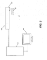
- FIG. 3 shows an intra-oral imaging system 42 with an imaging apparatus 100 that has a probe 120 for forming an image of surface contour and color shade for one or more teeth 20.
- a host processor 134 typically a computer workstation or other dedicated logic processor, collects and processes data from imaging apparatus 100 and typically provides this information on a display 38.
- Hand-held probe 120 can be easily positioned within the patient's mouth with little or no discomfort.
- Probe 120 communicates, over a wired or wireless data communication channel, with host processor 134.
- the logic flow diagram of Figure 4 shows the steps that are used for acquiring the combined image of surface contour and color shade in one embodiment.
- a positioning step S200 the operator positions probe 120 ( Figure 3 ) in the mouth of the patient.
- a shape imaging step S210 and a shade imaging step S220 are then executed in rapid succession in order to obtain color and contour information that can be registered to each other. Registration of the two types of images to each other can use any of a number of techniques well known to those skilled in the imaging arts and may involve, for example, detection of features that are clearly pronounced or readily identifiable in each of the two types of images.
- steps S210 and S220 can be executed in either order.
- shade imaging step S220 is executed first and its results are used to condition the performance of shape imaging step S210 that immediately follows. The use of this particular type of sequence is described in more detail subsequently.
- a combining step S230 the shade and shape information from the preceding steps is combined so that a single image with both contour and color shade data can be obtained, displayed, and stored in a display and store step S240.
- the schematic block diagram of Figure 5 shows an embodiment of an imaging apparatus 100 that is configured to obtain both fringe projection and color shade images.
- An illumination field generator 112 is energizable to form the needed illumination for both fringe projection imaging and color imaging.
- illumination field generator 112 For fringe projection imaging, illumination field generator 112 generates a pattern of features, which may also have variable intensity.
- illumination field generator 112 For color imaging, illumination field generator 112 generates a substantially uniform field with broadband spectrum or, alternately, two or more sequential and uniform fields with different wavelengths. Internal components and operation of illumination field generator 112 are described in more detail subsequently.
- the illumination from illumination field generator 112 is directed through a polarizer 14 and directed, as incident illumination, to tooth 20 through a projection lens 16.
- Light reflected and scattered from tooth 20 is provided to a detector 30, through an imaging lens 22 and a polarization-selective element such as an analyzer 28.
- Detector 30 is disposed along a detection path 88, at the image plane of imaging lens 22.
- a control logic processor 34 accepts and processes image data from detector 30 and passes the image data to host processor 134 ( Figure 3 ) and may use the image data to control its own operation, as described in more detail subsequently.
- Imaging apparatus 100 is used to perform fringe projection imaging in step S210 ( Figure 4 ), just prior to or just following color imaging.
- Control logic processor 34 ( Figure 5 ) configures components of imaging apparatus 100 for this function and obtains the contour image data from the tooth at detector 30.
- the illumination that is used for fringe projection imaging is blue light, in the 350-450 nm range.
- control logic processor 34 can be a computer, microprocessor, or other dedicated logic processing apparatus that executes programmed instructions.
- Intra-oral imaging apparatus 100 of Figure 5 uses polarized light for surface imaging of tooth 20.
- Polarizer 14 provides the fringe pattern illumination from illumination field generator 112 as linearly polarized light.
- the transmission axis of analyzer 28 is parallel to the transmission axis of polarizer 14. With this arrangement, only light with the same polarization as the fringe pattern is provided to the detector 30.
- analyzer 28, in the path of reflected light to detector 30, is rotated by an actuator 18 into either of two orientations as needed:
- the light that is available to the sensor can be (i) light reflected from the tooth top surface; (ii) light scattered or reflected from the near surface volume or portion of the tooth; and (iii) light scattered inside the tooth.
- the "near-surface volume" of the tooth is that portion of the tooth structure that lies within no more than a few hundred ⁇ m of the surface.
- the light reflected from the tooth surface (i), the specular light maintains the polarization state of the incident light. As the incident light propagates further into the tooth, the light is increasingly depolarized.
- some portion of the light (i) for a contour pattern may be incident on more highly reflective portions of the tooth surface, even causing some amount of saturation that degrades light detection.
- methods of the invention use at least portions of both the specular light (i) and the near-surface reflected light (ii), and avoid the light scattered deep inside the tooth (iii). It has been found that the near-surface light (ii), particularly for blue light and shorter wavelengths, is still substantially polarized. Thus, for example, a large portion of the light scattered and reflected from the superficial layer of the tooth enamel also has the same polarization state as the incident light and as the specular light (i).
- Figures 7A and 8A show why the apparatus and method of the present invention use scattered near-surface light from just beneath the surface of the tooth.
- Figures 8A and 8B show the difference between using the parallel polarization and cross-polarization.
- a polarized light P0 with small dimension illuminates the tooth
- some of the light P1 is reflected from the surface of the tooth in specular fashion and has the same polarization state as the illumination light P0.
- the other portion of the illumination light P0 goes into the tooth, is subject to scattering, and depolarizes.
- Some of the scattered light P2 escapes the tooth surface near the illumination region and can reach detector 30 ( Figure 5 ).
- the spatial "footprint" of the scattered light P2 which relates to the dimensions of pattern features of the structured light, such as line thicknesses, shows an increase over the corresponding spatial footprint of reflected light P1.
- the structured light pattern consists of parallel lines of light of a given thickness
- the reflected light P1 from these pattern features has lines of substantially the same thickness as the projected pattern.
- the scattered light P2 is detected as lines of slightly increased thickness. That is, since light P2 has been scattered inside the tooth, the projected footprint on the tooth surface is broader than that of the specular reflected light, which is the same size as the illumination beam that has been projected as incident light.
- the graph of Figure 7B shows the difference between the footprint of the light from the tooth surface (P1) and the light from inside the tooth (P2). To reduce the measurement error that can result, the light detected from inside the tooth should be minimized.
- the inventor has found that polarization provides an effective discriminator for separating the specular light (P1) from the tooth surface from the scattered light from inside the tooth, while still taking advantage of a portion of the scattered light (P2).
- one or more spatial light modulators can be used as part of illumination field generator 112 to provide the needed shifting motion for polarized fringe projection imaging, as described in more detail subsequently.
- the fringe pattern itself is shifted to at least one additional alternate position during imaging, more preferably to two or more alternate positions.
- This shifting of the light pattern can be caused by a separate actuator (not shown in Figure 5 ), such as a piezoelectric or other type of actuator that is part of illumination field generator 112 for achieving precision incremental movement.
- this shifting can be performed electronically, without mechanical movement of parts within illumination field generator 112.
- another actuator 18 can be positioned for providing 90 degree rotation to either polarizer 14 or analyzer 28 (such as is shown in Figure 5 ) in order to obtain both co-polarization and cross-polarization images.
- Polarization can also be rotated to respectively orthogonal positions when using an LCD spatial light modulator.
- imaging apparatus 100 also obtains a color image, or a number of monochromatic images with different illumination wavelengths to form a color image, using the same optical path components described with reference to Figure 5 .
- Illumination field generator 112 forms a substantially uniform illumination field rather than a pattern of contour features.
- the light is polychromatic, from Red (from about 630-700nm), Blue (from about 440-480nm) and Green (from about 500-540nm) sources. This illumination is again polarized by polarizer 14 and projected onto tooth-20.
- analyzer 28 can be positioned in cross-polarization orientation, that is, with its polarization transmission axis orthogonal to that of polarizer 14, as was described with reference to Figures 6B and 8B .
- This orientation is advantaged because it helps to reduce specular light which can cause saturation of the detector.
- analyzer 28 can be positioned in co-polarization orientation, that is, with its polarization transmission axis parallel to that of polarizer 14, as was described with reference to Figures 6A and 8A .
- the schematic block diagram of Figure 9 shows an embodiment of an intra-oral imaging apparatus 140 that obtains both fringe projection and color images and obtains light of both polarization states without requiring rotation of either polarizer 14 or analyzer 28 between image captures. A separate analyzer is not needed.
- a polarization beam splitter 36 acts as the polarization-selective element in detection path 88 and separates the reflected and scattered light, reflecting the cross-polarized light to a detector 30b and transmitting the co-polarized light to a detector 30a. Because it can use light of both polarization states, intra-oral imaging apparatus 140 can obtain more information for both shape and shade measurement.
- a blue-transmissive filter 90 is optional and may be needed when the ambient lighting is not otherwise blocked from detection path 88. In one embodiment, filter 90 is transmissive to light in the 350 - 500nm range.
- Detectors 30, 30a, or 30b in the embodiments described herein can be any of a number of types of image sensing array, such as a CCD device, for example.
- Polarizers and analyzers can be wire-grid or other polarizer types.
- Figure 10 shows an embodiment of illumination field generator 112 for forming both the fringe projection pattern used for contour imaging and the uniform illumination field used for color shade imaging.
- a light source 80 is used as the light source for fringe projection imaging.
- a monochromatic light source 80 can be a solid-state light source, such as a Light-Emitting Diode (LED) or laser, or can be a lamp or other light source. Blue or near UV light in the 350 - 400nm range is used for providing usable image content from near-surface portions of the tooth, as described earlier.
- a dichroic surface 92 transmits the 350 - 400nm light from light source 80 to a lens or other optical element 82.
- a polychromatic light source 78 shown comprising light sources 81r, 81g, and 81b in the Figure 10 embodiment, provides the needed polychromatic illumination for color shade imaging.
- light sources 81r, 8 1 g, and 8 1 b are red, blue, and green LEDs, respectively, energized simultaneously or in sequence for obtaining the color images.
- Alternate colors, or a different number of color light sources, such as solid-state light sources with different wavelength bands, could be used in other embodiments.
- a single white light source such as a white light LED, a lamp, an Organic LED (OLED), or one or more lasers or other solid-state light emitters or other light sources could be used for providing polychromatic illumination from light source 78.
- Dichroic surface 92 reflects the polychromatic light from light source 78 toward optical element 82.
- light source 80 could alternately be a broadband light source, with a filter provided in either the illumination path or along the detection path 88 or both illumination and detection paths for obtaining the fringe projection image.
- a single broadband light source is used for both fringe projection and color imaging, with a movable filter positioned in place by a motor or other actuator during fringe projection imaging and removed from the illumination path during color imaging.
- a spatial light modulator 84 is provided for forming the illumination beam.
- spatial light modulator 84 is a digital micromirror device (DMD), such as the Digital Light Processor (DLP TM ) from Texas Instruments, Dallas TX, for example.
- DMD digital micromirror device
- LCD Liquid Crystal Device
- spatial light modulator 84 forms the featured fringe projection pattern of structured light using illumination from monochromatic light source 80.
- spatial light modulator 84 forms a substantially uniform field of light that is then directed to the tooth.
- the spatial light modulator offers a number of advantages for shaping the illumination beam and forming the contour fringe pattern.
- the SLM's pixel-based control of light intensity enables correction for non-uniformity of the projected beam or pattern. This capability enables the SLM to compensate for non-uniformity of the light source, such as due to aging, for example.
- the SLM can dynamically change the projected illumination pattern for either contour imaging or shade imaging. For example, it may be advantageous to form a patterned illumination beam for shade measurement, using the same pattern or a different pattern from that used to obtain contour data.
- the SLM can also be used to provide one or more lines of light or one or more point sources, which may be advantaged for translucency measurement.
- contours of the tooth include surfaces that are steeply sloped with respect to each other, complicating the task of directing enough light onto each surface. As a result, some surfaces of the tooth may not provide 3-D information that is sufficient. Referring to Figures 11A-11C , this problem is represented relative to a rear surface 26 of tooth 20. Patterned light from imaging apparatus 10 generates a contour-detecting fringe pattern 44 onto tooth 20, as shown in Figure 11B .
- Fringe pattern 44 is sufficiently bright for obtaining 3-D image content over a top surface 46, as outlined over an area 52; however, the back surface area corresponding to rear surface 26 of tooth 20 and outlined as a darker area 54 is very dimly lit This allows only a coarse estimation, at best, of the contour of rear surface 26.
- an embodiment of the present invention selectively increases the light intensity of the projected fringe pattern illumination over a given area.
- a fringe pattern 50 is shown with two different areas, differentiated by their relative light intensities.
- a first intensity 56 is provided for fringe projection imaging of surfaces such as top surface 46 that are more readily accessible for contour imaging.
- a second intensity 58 higher than first intensity 56 for the example shown and as indicated by darker lines in Figure 11C , is provided for the back surface area of the tooth. It should be observed that the actual pattern feature spacing and thickness of the projected contour lines that are the pattern features in this example is not changed in this embodiment. The same spatial frequency of fringe pattern 50 is preserved.
- contour pattern, fringe pattern 50 remains dimensionally uniform, with individual lines or other pattern features changed only in intensity, rather than in dimension or spacing (period). Only the relative intensity of the fringe pattern illumination over one or more areas is increased where needed. For example, along any one line within structured light fringe pattern 50, there can be any number of intensities, such as the two shown as first and second intensities 56 and 58 in Figure 11C . The line thickness within the fringe pattern does not change; the spatial frequency of the fringe pattern is preserved.
- Maintaining dimensional uniformity and spatial frequency of the fringe pattern is advantageous for contour imaging because it provides a uniform resolution over the full image field.
- Other techniques have been proposed for changing the pattern dimensions itself, such as thickening the pattern lines over specific areas; however, because the spatial frequency of the fringe pattern changes when using such a technique, the resulting resolution of the contour image that is obtained is non-uniform.
- the example fringe pattern 50 given in. Figure 11C it is instructive to observe that if the area indicated as second intensity 58 actually used thicker lines, the resulting contour image would suffer reduced resolution over this area.
- embodiments of the present invention provide an increased illumination without loss of resolution over the darker region.
- Figures 11A-11C showed a simple case in which fringe pattern 50 compensates for surface steepness by using two different intensities 56 and 58.
- Figures 12A and 12B show examples of other possible arrangements that use more than two light intensities.
- light for the fringe pattern illumination can be of first intensity 56, second intensity 58, or a third intensity 66, represented as the highest intensity in this example.
- light can be of first, second, or third intensities 56, 58, or 66 respectively, or of an even higher fourth intensity 68 as shown.
- the light intensity can vary along any individual pattern feature, such as along a single line in the projected fringe pattern 50.
- the light intensity over the projected pattern can be changed by controlling illumination field generator 112 by means of commands from control logic processor 34, in response to programmed instructions, and by means of signals provided from control logic processor 34 to related control components. Intensity can then be increased over any portion of projected fringe pattern 50 by increasing the effective duty cycle of the rotatable mirrors of the DMD using Pulse-Width Modulation (PWM), so that the source illumination is provided for a suitable amount of time over a particular portion of the fringe pattern.
- PWM Pulse-Width Modulation
- Other methods of illumination intensity adjustment would apply for LCD and for other transmissive and emissive spatial light modulators, using light modulation techniques familiar to those skilled in the imaging arts.
- control logic processor 34 is programmed with instructions that automatically adapt the local intensities of lines or other features in fringe pattern 50 according to imaging conditions.
- color imaging of the tooth is performed first, and the color image analyzed to determine which portions of the illumination to intensify.
- an initial fringe projection image is captured and checked to determine areas for increasing or decreasing intensity for obtaining the contour image. Then, the actual contour image is captured using this information.
- the logic flow diagram of Figure 13 shows a sequence of steps that are used for adaptive fringe projection imaging in one embodiment.
- a first reference image is obtained.
- the reference image can be a contour image, formed by projecting structured light onto the tooth surface.
- the reference image can be a conventional two-dimensional image obtained from projection of a uniform field of light onto the tooth surface.
- the reference image that is obtained can be at full resolution; alternately, since the reference image is not used directly for imaging but instead to determine the overall amount of light that is returned over each surface area, the reference image can be at lower resolution.
- an analysis step S64 follows, in which areas from the sensed reference image that are not sufficiently bright are identified.
- analysis step S64 can take advantage of known data about tooth structure. The operator, for example, may identify the tooth by number or provide other information that is used in analysis step S64.
- a map generation step S70 is then executed, in which areas of greater or lesser intensity are defined according to the first reference image. With respect to Figures 12A and 12B , step S70 then sets up variable intensity fringe pattern 50.
- An image acquisition step S74 uses the generated fringe pattern 50 for obtaining a contour image with added brightness as described with respect to Figures 11A-11C .
- Image acquisition step S74 may be followed by an optional looping step S76 that repeats the analysis of map generation step S70 in order to generate a second or other additional mappings so that the projected structured illumination pattern can be shifted, with appropriate changes in intensity, one or more times. This shifting is done in order to obtain a more accurate evaluation of tooth contour using fringe projection techniques.
- image acquisition step S74 also includes energizing actuator 18 ( Figure 5 ) in order to obtain images using both co-polarization (as in Figure 6A ) and cross-polarization ( Figure 6B ).
- contour fringe pattern lines or the relative size of other pattern elements could be changed to provide additional light, or to reduce light, over portions of the tooth.
- contour imaging data would be at reduced resolution and shape computation processing more complex.
- Embodiments of the present invention provide both color imaging and improved contour imaging for teeth by taking advantage of properties of light and capabilities of spatial light modulators for forming an adaptive fringe projection pattern.
- the use of a spatial light modulator enables a fringe pattern of variable intensity to be formed, as well as a uniform illumination field for color imaging.
- the separate fringe projection and color images can be taken in rapid succession, minimizing problems with registering the shape and shade content in order to provide an accurate color 3-D image of the tooth or other structure.
- the apparatus and methods of the present invention compensate for problems related to the translucence of the tooth by using short-wavelength light for fringe projection imaging and by employing principles of polarized light for both fringe projection and color imaging.
- the image data obtained using the apparatus and methods of the present invention can be used for improving the accuracy and timeliness of fabrication for crowns and other dental prosthetics. This can help to reduce or eliminate the need for obtaining impression under some conditions, reducing the overall expense of dental care.
- the imaging performed using this method and apparatus can help to achieve superior-fitting prosthetic devices that install with little or no adjustment by the dentist.
- the apparatus and method of the present invention can be used for long-term tracking of tooth, support structure, and bite conditions, helping to diagnose and prevent more serious health problems.
- the data generated using this system can be used to help improve communication between patient and dentist and between the dentist, staff, and lab facilities.
- the apparatus and method of the present invention provide an intra-oral imaging system for 3-D imaging of teeth and other dental features without requiring the use of a special powder or application of some other temporary coating for the tooth surface.
- the system offers high resolution, in the 25-50 ⁇ m range in one embodiment.
Abstract
Description
- The invention generally relates to the field of diagnostic imaging and more particularly relates to an apparatus and method for combined three-dimensional shape and color shade imaging of the surface of teeth and other structures.
- Accurately modeling both the shape and color shade of a tooth are important functions for providing restorative dentistry and related services. Conventionally, the functions of determining tooth contour and matching tooth shade have been performed as separate operations. This makes it difficult to register or correlate the shade information to the shape information. Color shade decisions in particular are subject to human error and the overall accuracy often depends on the relative experience of the practitioner.
- With the advent of digital imaging technologies, a number of tools have been made available for obtaining either surface contour data or color shade information from the tooth. One technology that has been adapted for obtaining tooth contour is fringe projection imaging. Fringe projection imaging uses patterned or structured light to obtain surface contour information for structures of various types. In fringe projection imaging, a pattern of lines of an interference fringe or grating is projected toward the surface of an object from a given direction. The projected pattern from the surface is then viewed from another direction as a contour image, taking advantage of triangulation in order to analyze surface information based on the appearance of contour lines. Phase shifting, in which the projected pattern is incrementally spatially shifted for obtaining additional measurements at the new locations, is typically applied as part of fringe projection imaging, used in order to complete the contour mapping of the surface and to increase overall resolution in the contour image.
- Fringe projection imaging has been used for surface contour imaging of solid, highly opaque objects and has been used for imaging the surface contours for some portions of the human body and for obtaining detailed data about skin structure. However, a number of technical obstacles have prevented effective use of fringe projection imaging of the tooth. One challenge with dental surface imaging relates to tooth translucency. Translucent or semi-translucent materials in general are known to be particularly troublesome for fringe projection imaging. Subsurface scattering in translucent structures can reduce the overall signal-to-noise (S/N) ratio and shift the light intensity, causing inaccurate height data. Another challenge relates to high levels of reflection for various tooth surfaces. Highly reflective materials, particularly hollowed reflective structures, can effectively reduce the dynamic range of this type of imaging.
- In fringe projection imaging overall, contrast is typically poor, with noise as a significant factor. To improve contrast, some fringe projection imaging systems take measures to reduce the amount of noise in the contour image. In general, for accurate surface geometry measurement using fringe imaging techniques, it is desired to obtain the light that is directly reflected from the surface of a structure under test and to reject light that is reflected from material or structures that lie beneath the surface. This is an approach for 3D surface scanning of translucent objects.
- From an optics perspective, the structure of the tooth itself presents a number of additional challenges for fringe projection imaging. As noted earlier, light penetrating beneath the surface of the tooth tends to undergo significant scattering within the translucent tooth material. Moreover, reflection from opaque features beneath the tooth surface can also occur, adding noise that degrades the sensed signal and thus further complicating the task of tooth surface analysis.
- One corrective measure that has been attempted to make fringe projection workable for contour imaging of the tooth is application of a coating that changes the reflective characteristics of the tooth surface itself. Here, to compensate for problems caused by the relative translucence of the tooth, a number of conventional tooth contour imaging systems apply a paint or reflective powder to the tooth surface prior to surface contour imaging. For the purposes of fringe projection imaging, this added step enhances the opacity of the tooth and reduces or eliminates the scattered light effects noted earlier. However, there are drawbacks to this type of approach. The step of applying a coating powder or liquid adds cost and time to the tooth contour imaging process. Because the thickness of the coating layer itself has a given thickness and is often non-uniform over the entire tooth surface, measurement errors readily result. No information on relative translucency of the tooth is available when the coating is applied. Further, the applied coating, while it facilitates contour imaging, can tend to mask other problems with the tooth and can thus reduce the overall amount of information that can be obtained. Even where a coating or other type of surface conditioning of the tooth is used, it can still be difficult to provide sufficient amounts of light onto, and to sense light reflected back from, all of the tooth surfaces. Different surfaces of the tooth can be oriented at 90 degrees relative to each other, making it difficult to direct enough light for accurately imaging all parts of the tooth, whether or not a coating is applied.
- There have been attempts to adapt structured light surface-profiling techniques to the challenges of tooth structure imaging. For example,
U.S. Patent No. 5,372,502 entitled "Optical Probe and Method for the Three-Dimensional Surveying of Teeth" to Massen et al. describes the use of an LCD matrix to form patterns of stripes for projection onto the tooth surface. Another approach is described inU.S. Patent Application Publication 2007/0086762 entitled "Front End for 3-D Imaging Camera" byO'Keefe et al. U.S. Patent No. 7,312,924 entitled "Polarizing Multiplexer and Methods for Intra-Oral Scanning" to Trissel describes a method for profiling the tooth surface using triangularization and polarized light, but needing application of a fluorescent coating for operation. Further,U.S. Patent No. 6,885,464 entitled "3-D Camera for Recording Surface Structures, In Particular for Dental Purposes" to Pfeiffer et al. discloses a dental imaging apparatus using triangularization but also requiring the application of an opaque powder to the tooth surface for imaging. - The use of a powder or other surface coating, which may help facilitate contour imaging, prevents color shade information from being obtained at the same time. Thus, color shade information and surface contour information must be obtained separately, making it difficult to register the shade and shape information to each other.
- An approach to obtaining both shape and shade information from one apparatus uses confocal imaging is described in
U.S. Patent No. 7,319,529 entitled "Method and Apparatus for Colour Imaging a Three-Dimensional Structure" to Babayoff. As best understood, a few hundred images of the tooth are taken, at incremental focus distances, and relative pixel intensity is used as a measure of surface contour for multiple points on the tooth surface. Color and depth data thus obtained are then combined in order to obtain and display the shape and color shade of-the tooth. - While confocal imaging methods may have some advantages, there are disadvantages to using such methods. Considerable image processing resources can be required with such an approach, depending on the pixel resolution used. When this processing is done externally at a connected host computer or processor, there can be considerable overhead due to the needed volume of data transferred to the host computer or processor for confocal devices. There are also disadvantages related to optical components and design. Optical path requirements differ between what is efficient and beneficial for shape measurement and what is needed to effectively measure tooth color shade. Confocal imaging requires telecentric illumination and imaging paths, thus limiting the field of view of the imaging device.
- It can be appreciated that an apparatus and method that provides both accurate surface contour imaging of the tooth and color shade data would help to speed reconstructive dentistry and could help to lower the inherent costs and inconvenience of conventional methods, such as those for obtaining a cast or other surface profile for a crown, implant, or other restorative structure.
- It is an object of the present invention to advance the art of diagnostic imaging, particularly for intra-oral imaging applications. With this object in mind, the present invention provides an intra-oral imaging apparatus comprising: an illumination field generator comprising a spatial light modulator actuable to form an illumination beam having a contour fringe projection pattern when receiving incident light from a first light source and having a substantially uniform illumination field when receiving incident light from a second light source; a polarizer in the path of the illumination beam emitted from the illumination field generator and having a first polarization transmission axis; a projection lens disposed to direct the polarized illumination beam as incident illumination toward a tooth surface; an imaging lens disposed to direct at least a portion of the light reflected and scattered from the incident illumination at the tooth surface along a detection path; a polarization-selective element disposed along the detection path and having a second polarization transmission axis; at least one detector disposed along the detection path for obtaining image data from the light provided through the polarization-selective element; and a control logic processor responsive to programmed instructions for alternately energizing the first and second light sources in a sequence and obtaining both contour fringe projection data and color image data from the at least one detector.
- It is a feature of the present invention that it applies light of suitable polarization and wavelength along with fringe projection patterning of varying brightness to the task of tooth contour imaging.
- An advantage offered by the apparatus and method of the present invention relates to improved imaging of tooth surfaces and obtaining tooth shade information at lower cost over conventional contour imaging methods. Unlike conventional methods, no powder or other opaque substance must be applied to the tooth as a preparatory step for contour imaging.
- These objects are given only by way of illustrative example, and such objects may be exemplary of one or more embodiments of the invention. Other desirable objectives and advantages inherently achieved by the disclosed invention may occur or become apparent to those skilled in the art. The invention is defined by the appended claims.
- The foregoing and other objects, features, and advantages of the invention will be apparent from the following more particular description of the embodiments of the invention, as illustrated in the accompanying drawings.
- The elements of the drawings are not necessarily to scale relative to each other.
-
FIG. 1 is a workflow diagram showing the role of the imaging apparatus and method of the present invention in the sequence for providing a dental prosthetic appliance. -
FIG. 2A is a diagram showing wavelength-dependent penetration of illumination incident on the tooth. -
FIG. 2B is a schematic diagram showing relative intensities of reflected and scattered light with different wavelengths. -
FIG. 3 is a block diagram showing components of an intra-oral imaging system according to one embodiment. -
FIG. 4 is a logic flow diagram for obtaining combined shape and color shade information for a tooth or other structure. -
FIG. 5 is a schematic diagram of an imaging apparatus for obtaining combined shape and color shade information in one embodiment. -
FIG. 6A is a block diagram showing the use of an analyzer with its polarization axis in parallel to the polarizer of a polarized fringe projection imaging apparatus. -
FIG. 6B is a block diagram showing the use of an analyzer with its polarization axis orthogonal to the polarizer of a polarized fringe projection imaging apparatus. -
FIG. 7A is a diagram that shows the polarization-dependent reflection and scattering of illumination incident on the tooth. -
FIG. 7B is a diagram showing the relative intensities of reflected light and the scattered light from incident illumination. -
FIG. 8A shows the components of light obtained when detecting co-polarized light. -
FIG. 8B shows the components of light obtained when detecting cross-polarized light. -
FIG. 9 is a schematic diagram of an imaging apparatus for obtaining combined shape and color shade information in an embodiment that uses multiple detectors. -
FIG. 10 is a schematic diagram showing an illumination field generator in one embodiment of the present invention. -
FIGS. 11A-11C are schematic diagrams showing how increased brightness can be applied for improved imaging over a portion of the imaging field with contoured surfaces. -
FIGS. 12A and 12B show exemplary projected light patterns generated for contour imaging in one embodiment. -
FIG. 13 is a logic flow diagram that shows the sequence for obtaining a contour-compensated image. - Reference is made to
U.S. Patent Application U.S. Serial No. 12/424,562 - Figures provided herein are given in order to illustrate key principles of operation and component relationships along their respective optical paths according to the present invention and are not drawn with intent to show actual size or scale. Some exaggeration may be necessary in order to emphasize basic structural relationships or principles of operation. Some conventional components that would be needed for implementation of the described embodiments, such as support components used for providing power, for packaging, and for mounting and protecting system optics, for example, are not shown in the drawings in order to simplify description of the invention itself. In the drawings and text that follow, like components are designated with like reference numerals, and similar descriptions concerning components and arrangement or interaction of components already described are omitted.
- In the context of the present disclosure, the term "fringe pattern illumination" is used to describe the type of structured illumination that is used for fringe projection imaging or "contour" imaging. The fringe pattern itself can include, as pattern features, multiple lines, circles, curves, or other geometric shapes that are distributed over the area that is illuminated and that have a predetermined spatial frequency, recurring at a given period.
- Two portions of a line of light or other feature in a pattern of structured illumination can be considered to be substantially "dimensionally uniform" when their projected line width is the same over the length of the line to within no more that +/- 15 percent. As is described in more detail subsequently, dimensional uniformity of the pattern of structured illumination is needed to maintain a uniform spatial frequency.
- In the context of the present disclosure, a "substantially uniform" beam of light exhibits no visibly perceptible change in intensity over its field.
- In order to more fully appreciate the problems addressed by the present invention, it is instructive to consider how the apparatus and methods of the present invention serve the overall workflow for designing, fabricating, and installing a crown or other color-matched dental prosthesis. Referring to the workflow diagram of
Figure 1 , this process begins with an image capture step S 160 that obtains images used to determine the appropriate shape and shade of existing tooth structure. Fringe projection images are used to generate 3-D shape information in a shape construction step S164. Color images or monochromatic images with different illumination wavelengths are used to provide the color information needed in a shade extraction step S168. A color 3-D image generation step S 170 then forms a color image using the combined shade and shape data. A prosthesis specification step S 174 then uses this and other information for specifying materials and other features of the crown or other dental prosthesis. A prototyping step S 178 enables visualization of the prosthetic appliance, such as on a color display for example. A customer approval step S 180 follows, in which the dental practitioner approves the prototype. Once approved, a fabrication step S 184 proceeds, using the shade and shape data and prototyping information generated therefrom. An installation step S 188 follows in which the crown or other dental appliance is fitted to the patient and any necessary minor adjustments made. Lastly, a checkup step S190 is carried out. - For the workflow outlined in
Figure 1 , the present invention concerns itself primarily with image capture step S 160, shape construction step S164, shade extraction step S168, and subsequent color 3-D image generation step S170. - In general, the problem of obtaining contour information from a tooth for shape construction step S164 requires techniques and approaches that may run counter to requirements for obtaining a color image in shade extraction step S168. For example, contour imaging, because it uses a gray level output, works best with a monochrome light source, rather than with a polychromatic source; the use of a narrow band of wavelengths for the structured light pattern simplifies fringe pattern detection and inherently reduces the effects of stray ambient light, for example. For dental imaging in particular, it has been found that light of shorter wavelengths is advantaged over other light for contour imaging of the tooth because of tooth translucence and consequent scattering, which varies by wavelength. An additional difference between fringe projection imaging and color shade imaging relates to the uniformity of light intensity that is advantageous for each type, as is described in more detail subsequently.
- The effect of wavelength on light scattering for the tooth is represented in the diagram of
Figure 2A and corresponding graph ofFigure 2B. Figure 2A shows three different wavelengths λ1, λ2, and λ3 as directed toward atooth 20. The shortest wavelength at λ1 penetrates the tooth the shortest distance. The next longest wavelength at λ2 penetrates the tooth an additional distance. Finally, the longest wavelength at λ3 penetrates the tooth the farthest distance. The graph ofFigure 2B shows how scattering affects the footprint of the light on the tooth surface from each wavelength. The longer the wavelength, the larger the footprint, resulting in larger measurement error. Wavelength λ1 could be near-UV or blue light in the range of 350 to 500 nm, for example. Wavelength λ2 could be green light in the range of 500 to 700 nm, for example. Wavelength λ3 could be red or IR light in the range of 700nm or higher, for example. Thus, blue or near UV light in the 350-500 nm range, because it provides the least penetration into the tooth structure, proves to be a suitable light source for fringe projection imaging in one embodiment. - The schematic diagram of
Figure 3 shows anintra-oral imaging system 42 with animaging apparatus 100 that has aprobe 120 for forming an image of surface contour and color shade for one ormore teeth 20. Ahost processor 134, typically a computer workstation or other dedicated logic processor, collects and processes data fromimaging apparatus 100 and typically provides this information on adisplay 38. Hand-heldprobe 120 can be easily positioned within the patient's mouth with little or no discomfort.Probe 120 communicates, over a wired or wireless data communication channel, withhost processor 134. - The logic flow diagram of
Figure 4 shows the steps that are used for acquiring the combined image of surface contour and color shade in one embodiment. In a positioning step S200, the operator positions probe 120 (Figure 3 ) in the mouth of the patient. A shape imaging step S210 and a shade imaging step S220 are then executed in rapid succession in order to obtain color and contour information that can be registered to each other. Registration of the two types of images to each other can use any of a number of techniques well known to those skilled in the imaging arts and may involve, for example, detection of features that are clearly pronounced or readily identifiable in each of the two types of images. - Still referring to
Figure 4 , steps S210 and S220 can be executed in either order. In one embodiment, shade imaging step S220 is executed first and its results are used to condition the performance of shape imaging step S210 that immediately follows. The use of this particular type of sequence is described in more detail subsequently. In a combining step S230, the shade and shape information from the preceding steps is combined so that a single image with both contour and color shade data can be obtained, displayed, and stored in a display and store step S240. - The schematic block diagram of
Figure 5 shows an embodiment of animaging apparatus 100 that is configured to obtain both fringe projection and color shade images. Anillumination field generator 112 is energizable to form the needed illumination for both fringe projection imaging and color imaging. For fringe projection imaging,illumination field generator 112 generates a pattern of features, which may also have variable intensity. For color imaging,illumination field generator 112 generates a substantially uniform field with broadband spectrum or, alternately, two or more sequential and uniform fields with different wavelengths. Internal components and operation ofillumination field generator 112 are described in more detail subsequently. - Still referring to
Figure 5 , the illumination fromillumination field generator 112 is directed through apolarizer 14 and directed, as incident illumination, totooth 20 through aprojection lens 16. Light reflected and scattered fromtooth 20 is provided to adetector 30, through animaging lens 22 and a polarization-selective element such as ananalyzer 28.Detector 30 is disposed along adetection path 88, at the image plane ofimaging lens 22. Acontrol logic processor 34 accepts and processes image data fromdetector 30 and passes the image data to host processor 134 (Figure 3 ) and may use the image data to control its own operation, as described in more detail subsequently. -
Imaging apparatus 100 is used to perform fringe projection imaging in step S210 (Figure 4 ), just prior to or just following color imaging. Control logic processor 34 (Figure 5 ) configures components ofimaging apparatus 100 for this function and obtains the contour image data from the tooth atdetector 30. In one embodiment, the illumination that is used for fringe projection imaging is blue light, in the 350-450 nm range. - One function of
control logic processor 34 during fringe projection imaging is to incrementally shift the position of the fringe and trigger the detector to capture images that are then used to calculate three-dimensional information about the tooth surface. For the phase shifting fringe projection method, at least three images are typically needed in order to provide enough information for calculating the three-dimensional information of the object. The relative positions of the fringes for these three projected images are typically shifted by one-third of the fringe period.Control logic processor 34 can be a computer, microprocessor, or other dedicated logic processing apparatus that executes programmed instructions. -
Intra-oral imaging apparatus 100 ofFigure 5 uses polarized light for surface imaging oftooth 20.Polarizer 14 provides the fringe pattern illumination fromillumination field generator 112 as linearly polarized light. In one embodiment, the transmission axis ofanalyzer 28 is parallel to the transmission axis ofpolarizer 14. With this arrangement, only light with the same polarization as the fringe pattern is provided to thedetector 30. In another embodiment,analyzer 28, in the path of reflected light todetector 30, is rotated by anactuator 18 into either of two orientations as needed: - (a) Same polarization transmission axis as
polarizer 14. In this "co-polarization" position,detector 30 obtains the specular light reflected from the surface oftooth 20, and most of the light scattered and reflected from the superficial layer of enamel surface oftooth 20, as well as some of the light scattered back from sub-surface portions of the tooth. The co-polarization orientation of the analyzer 28 axis is shown inFigure 6A . Parallel or co-polarization provides improved contrast over other configurations. - (b) Orthogonal polarization transmission axis relative to polarizer 14. Using the orthogonal polarization, or cross-polarization, helps to reduce the specular component from the tooth surface and to obtain more of the scattered light from inner portions of the tooth. The cross-polarization orientation of the analyzer 28 axis is shown in
Figure 6B . - When the tooth is imaged with an imaging system and sensor, the light that is available to the sensor can be (i) light reflected from the tooth top surface; (ii) light scattered or reflected from the near surface volume or portion of the tooth; and (iii) light scattered inside the tooth. In the context of the present disclosure, the "near-surface volume" of the tooth is that portion of the tooth structure that lies within no more than a few hundred µm of the surface.
- It is known that the light reflected from the tooth surface (i), the specular light, maintains the polarization state of the incident light. As the incident light propagates further into the tooth, the light is increasingly depolarized.
- Disadvantageously, some portion of the light (i) for a contour pattern may be incident on more highly reflective portions of the tooth surface, even causing some amount of saturation that degrades light detection. In contrast to conventional approaches that use all the light from the tooth, methods of the invention use at least portions of both the specular light (i) and the near-surface reflected light (ii), and avoid the light scattered deep inside the tooth (iii). It has been found that the near-surface light (ii), particularly for blue light and shorter wavelengths, is still substantially polarized. Thus, for example, a large portion of the light scattered and reflected from the superficial layer of the tooth enamel also has the same polarization state as the incident light and as the specular light (i).
-
Figures 7A and8A show why the apparatus and method of the present invention use scattered near-surface light from just beneath the surface of the tooth.Figures 8A and 8B show the difference between using the parallel polarization and cross-polarization. When a polarized light P0 with small dimension illuminates the tooth, some of the light P1 is reflected from the surface of the tooth in specular fashion and has the same polarization state as the illumination light P0. The other portion of the illumination light P0 goes into the tooth, is subject to scattering, and depolarizes. Some of the scattered light P2 escapes the tooth surface near the illumination region and can reach detector 30 (Figure 5 ). - Significantly, the spatial "footprint" of the scattered light P2, which relates to the dimensions of pattern features of the structured light, such as line thicknesses, shows an increase over the corresponding spatial footprint of reflected light P1. For example, where the structured light pattern consists of parallel lines of light of a given thickness, the reflected light P1 from these pattern features has lines of substantially the same thickness as the projected pattern. However, the scattered light P2 is detected as lines of slightly increased thickness. That is, since light P2 has been scattered inside the tooth, the projected footprint on the tooth surface is broader than that of the specular reflected light, which is the same size as the illumination beam that has been projected as incident light. The graph of
Figure 7B shows the difference between the footprint of the light from the tooth surface (P1) and the light from inside the tooth (P2). To reduce the measurement error that can result, the light detected from inside the tooth should be minimized. The inventor has found that polarization provides an effective discriminator for separating the specular light (P1) from the tooth surface from the scattered light from inside the tooth, while still taking advantage of a portion of the scattered light (P2). - For the embodiment of
Figure 5 , one or more spatial light modulators can be used as part ofillumination field generator 112 to provide the needed shifting motion for polarized fringe projection imaging, as described in more detail subsequently. The fringe pattern itself is shifted to at least one additional alternate position during imaging, more preferably to two or more alternate positions. This shifting of the light pattern can be caused by a separate actuator (not shown inFigure 5 ), such as a piezoelectric or other type of actuator that is part ofillumination field generator 112 for achieving precision incremental movement. Alternately, whereillumination field generator 112 uses a spatial light modulator, this shifting can be performed electronically, without mechanical movement of parts withinillumination field generator 112. In addition, anotheractuator 18 can be positioned for providing 90 degree rotation to eitherpolarizer 14 or analyzer 28 (such as is shown inFigure 5 ) in order to obtain both co-polarization and cross-polarization images. Polarization can also be rotated to respectively orthogonal positions when using an LCD spatial light modulator. - Just following or just preceding fringe projection imaging,
imaging apparatus 100 also obtains a color image, or a number of monochromatic images with different illumination wavelengths to form a color image, using the same optical path components described with reference toFigure 5 .Illumination field generator 112 forms a substantially uniform illumination field rather than a pattern of contour features. The light is polychromatic, from Red (from about 630-700nm), Blue (from about 440-480nm) and Green (from about 500-540nm) sources. This illumination is again polarized bypolarizer 14 and projected onto tooth-20. The light returned fromtooth 20 is directed throughanalyzer 28, which can be positioned in cross-polarization orientation, that is, with its polarization transmission axis orthogonal to that ofpolarizer 14, as was described with reference toFigures 6B and8B . This orientation is advantaged because it helps to reduce specular light which can cause saturation of the detector. Alternately,analyzer 28 can be positioned in co-polarization orientation, that is, with its polarization transmission axis parallel to that ofpolarizer 14, as was described with reference toFigures 6A and8A . - The use of a
single detector 30 as shown in the embodiment ofFigure 5 is advantaged for its low parts count and the use of the same image path and components for both fringe projection and color shade imaging. However, this embodiment can be somewhat sensitive to ambient light under some conditions. - The schematic block diagram of
Figure 9 shows an embodiment of anintra-oral imaging apparatus 140 that obtains both fringe projection and color images and obtains light of both polarization states without requiring rotation of eitherpolarizer 14 oranalyzer 28 between image captures. A separate analyzer is not needed. Apolarization beam splitter 36 acts as the polarization-selective element indetection path 88 and separates the reflected and scattered light, reflecting the cross-polarized light to adetector 30b and transmitting the co-polarized light to adetector 30a. Because it can use light of both polarization states,intra-oral imaging apparatus 140 can obtain more information for both shape and shade measurement. A blue-transmissive filter 90 is optional and may be needed when the ambient lighting is not otherwise blocked fromdetection path 88. In one embodiment,filter 90 is transmissive to light in the 350 - 500nm range. -
Detectors -
Figure 10 shows an embodiment ofillumination field generator 112 for forming both the fringe projection pattern used for contour imaging and the uniform illumination field used for color shade imaging. In the embodiment ofFigure 10 , alight source 80 is used as the light source for fringe projection imaging. A monochromaticlight source 80 can be a solid-state light source, such as a Light-Emitting Diode (LED) or laser, or can be a lamp or other light source. Blue or near UV light in the 350 - 400nm range is used for providing usable image content from near-surface portions of the tooth, as described earlier. Adichroic surface 92 transmits the 350 - 400nm light fromlight source 80 to a lens or otheroptical element 82. A polychromaticlight source 78, shown comprisinglight sources Figure 10 embodiment, provides the needed polychromatic illumination for color shade imaging. In one embodiment,light sources 81r, 8 1 g, and 8 1 b are red, blue, and green LEDs, respectively, energized simultaneously or in sequence for obtaining the color images. Alternate colors, or a different number of color light sources, such as solid-state light sources with different wavelength bands, could be used in other embodiments. Alternately, a single white light source, such as a white light LED, a lamp, an Organic LED (OLED), or one or more lasers or other solid-state light emitters or other light sources could be used for providing polychromatic illumination fromlight source 78.Dichroic surface 92 reflects the polychromatic light fromlight source 78 towardoptical element 82. - It should be noted that
light source 80 could alternately be a broadband light source, with a filter provided in either the illumination path or along thedetection path 88 or both illumination and detection paths for obtaining the fringe projection image. In an alternate embodiment, a single broadband light source is used for both fringe projection and color imaging, with a movable filter positioned in place by a motor or other actuator during fringe projection imaging and removed from the illumination path during color imaging. - Still referring to
Figure 10 , a spatiallight modulator 84 is provided for forming the illumination beam. In one embodiment, spatiallight modulator 84 is a digital micromirror device (DMD), such as the Digital Light Processor (DLP™) from Texas Instruments, Dallas TX, for example. A Liquid Crystal Device (LCD) or other electronically controlled light modulator could alternately be used. For fringe projection imaging, spatiallight modulator 84 forms the featured fringe projection pattern of structured light using illumination from monochromaticlight source 80. For color imaging, spatiallight modulator 84 forms a substantially uniform field of light that is then directed to the tooth. - The spatial light modulator (SLM) offers a number of advantages for shaping the illumination beam and forming the contour fringe pattern. As one advantage, the SLM's pixel-based control of light intensity enables correction for non-uniformity of the projected beam or pattern. This capability enables the SLM to compensate for non-uniformity of the light source, such as due to aging, for example. The SLM can dynamically change the projected illumination pattern for either contour imaging or shade imaging. For example, it may be advantageous to form a patterned illumination beam for shade measurement, using the same pattern or a different pattern from that used to obtain contour data. The SLM can also be used to provide one or more lines of light or one or more point sources, which may be advantaged for translucency measurement.
- As was noted in the background material given earlier, the pronounced contours of the tooth include surfaces that are steeply sloped with respect to each other, complicating the task of directing enough light onto each surface. As a result, some surfaces of the tooth may not provide 3-D information that is sufficient. Referring to
Figures 11A-11C , this problem is represented relative to arear surface 26 oftooth 20. Patterned light fromimaging apparatus 10 generates a contour-detectingfringe pattern 44 ontotooth 20, as shown inFigure 11B .Fringe pattern 44 is sufficiently bright for obtaining 3-D image content over atop surface 46, as outlined over anarea 52; however, the back surface area corresponding to rearsurface 26 oftooth 20 and outlined as adarker area 54 is very dimly lit This allows only a coarse estimation, at best, of the contour ofrear surface 26. - In order to compensate for this lack of brightness using conventional fringe projection patterning techniques, an embodiment of the present invention selectively increases the light intensity of the projected fringe pattern illumination over a given area. In
Figure 11C , afringe pattern 50 is shown with two different areas, differentiated by their relative light intensities. Infringe pattern 50, afirst intensity 56 is provided for fringe projection imaging of surfaces such astop surface 46 that are more readily accessible for contour imaging. Asecond intensity 58, higher thanfirst intensity 56 for the example shown and as indicated by darker lines inFigure 11C , is provided for the back surface area of the tooth. It should be observed that the actual pattern feature spacing and thickness of the projected contour lines that are the pattern features in this example is not changed in this embodiment. The same spatial frequency offringe pattern 50 is preserved. This means that the contour pattern,fringe pattern 50, remains dimensionally uniform, with individual lines or other pattern features changed only in intensity, rather than in dimension or spacing (period). Only the relative intensity of the fringe pattern illumination over one or more areas is increased where needed. For example, along any one line within structuredlight fringe pattern 50, there can be any number of intensities, such as the two shown as first andsecond intensities Figure 11C . The line thickness within the fringe pattern does not change; the spatial frequency of the fringe pattern is preserved. - Maintaining dimensional uniformity and spatial frequency of the fringe pattern is advantageous for contour imaging because it provides a uniform resolution over the full image field. Other techniques have been proposed for changing the pattern dimensions itself, such as thickening the pattern lines over specific areas; however, because the spatial frequency of the fringe pattern changes when using such a technique, the resulting resolution of the contour image that is obtained is non-uniform. With respect to the
example fringe pattern 50 given in.Figure 11C , it is instructive to observe that if the area indicated assecond intensity 58 actually used thicker lines, the resulting contour image would suffer reduced resolution over this area. By maintaining the lines offringe pattern 50 as dimensionally uniform and only increasing the intensity of light to providesecond intensity 58 in this example, embodiments of the present invention provide an increased illumination without loss of resolution over the darker region. - The schematic diagrams of
Figures 11A-11C showed a simple case in whichfringe pattern 50 compensates for surface steepness by using twodifferent intensities Figures 12A and 12B show examples of other possible arrangements that use more than two light intensities. InFigure 12A , for example, light for the fringe pattern illumination can be offirst intensity 56,second intensity 58, or athird intensity 66, represented as the highest intensity in this example. In Figure 9B, light can be of first, second, orthird intensities fourth intensity 68 as shown. The light intensity can vary along any individual pattern feature, such as along a single line in the projectedfringe pattern 50. - In addition to increasing the light intensity over darker areas of the tooth surface relative to the position of
imaging apparatus 10, it is also possible to reduce the light intensity over areas where there may be highly specular reflection that otherwise causes saturation of the detector. Again, it must be emphasized that what changes is the light intensity over one or more portions of the projected light pattern; line thickness and spacing, both related to the spatial frequency, remain the same for different intensities. - Referring back to the block diagrams of
Figures 5 or9 , the light intensity over the projected pattern can be changed by controllingillumination field generator 112 by means of commands fromcontrol logic processor 34, in response to programmed instructions, and by means of signals provided fromcontrol logic processor 34 to related control components. Intensity can then be increased over any portion of projectedfringe pattern 50 by increasing the effective duty cycle of the rotatable mirrors of the DMD using Pulse-Width Modulation (PWM), so that the source illumination is provided for a suitable amount of time over a particular portion of the fringe pattern. Other methods of illumination intensity adjustment would apply for LCD and for other transmissive and emissive spatial light modulators, using light modulation techniques familiar to those skilled in the imaging arts. - Referring back to
Figures 5 and9 ,control logic processor 34 is programmed with instructions that automatically adapt the local intensities of lines or other features infringe pattern 50 according to imaging conditions. In one embodiment, color imaging of the tooth is performed first, and the color image analyzed to determine which portions of the illumination to intensify. In another embodiment, an initial fringe projection image is captured and checked to determine areas for increasing or decreasing intensity for obtaining the contour image. Then, the actual contour image is captured using this information. - The logic flow diagram of
Figure 13 shows a sequence of steps that are used for adaptive fringe projection imaging in one embodiment. In an initial step S60 a first reference image is obtained. The reference image can be a contour image, formed by projecting structured light onto the tooth surface. Alternately, the reference image can be a conventional two-dimensional image obtained from projection of a uniform field of light onto the tooth surface. The reference image that is obtained can be at full resolution; alternately, since the reference image is not used directly for imaging but instead to determine the overall amount of light that is returned over each surface area, the reference image can be at lower resolution. - Still referring to
Figure 13 , an analysis step S64 follows, in which areas from the sensed reference image that are not sufficiently bright are identified. For dental imaging applications, analysis step S64 can take advantage of known data about tooth structure. The operator, for example, may identify the tooth by number or provide other information that is used in analysis step S64. A map generation step S70 is then executed, in which areas of greater or lesser intensity are defined according to the first reference image. With respect toFigures 12A and 12B , step S70 then sets up variableintensity fringe pattern 50. An image acquisition step S74 then uses the generatedfringe pattern 50 for obtaining a contour image with added brightness as described with respect toFigures 11A-11C . Image acquisition step S74 may be followed by an optional looping step S76 that repeats the analysis of map generation step S70 in order to generate a second or other additional mappings so that the projected structured illumination pattern can be shifted, with appropriate changes in intensity, one or more times. This shifting is done in order to obtain a more accurate evaluation of tooth contour using fringe projection techniques. The individually obtained contour images are combined to obtain surface structure information, using techniques well known in the imaging arts. In one embodiment, image acquisition step S74 also includes energizing actuator 18 (Figure 5 ) in order to obtain images using both co-polarization (as inFigure 6A ) and cross-polarization (Figure 6B ). - It should be noted that, in an alternate embodiment, the thickness of contour fringe pattern lines or the relative size of other pattern elements could be changed to provide additional light, or to reduce light, over portions of the tooth. However, contour imaging data would be at reduced resolution and shape computation processing more complex.
- Embodiments of the present invention provide both color imaging and improved contour imaging for teeth by taking advantage of properties of light and capabilities of spatial light modulators for forming an adaptive fringe projection pattern. The use of a spatial light modulator enables a fringe pattern of variable intensity to be formed, as well as a uniform illumination field for color imaging. The separate fringe projection and color images can be taken in rapid succession, minimizing problems with registering the shape and shade content in order to provide an accurate color 3-D image of the tooth or other structure. The apparatus and methods of the present invention compensate for problems related to the translucence of the tooth by using short-wavelength light for fringe projection imaging and by employing principles of polarized light for both fringe projection and color imaging.
- As described earlier with respect to
Figure 1 , the image data obtained using the apparatus and methods of the present invention can be used for improving the accuracy and timeliness of fabrication for crowns and other dental prosthetics. This can help to reduce or eliminate the need for obtaining impression under some conditions, reducing the overall expense of dental care. Thus, the imaging performed using this method and apparatus can help to achieve superior-fitting prosthetic devices that install with little or no adjustment by the dentist. From another aspect, the apparatus and method of the present invention can be used for long-term tracking of tooth, support structure, and bite conditions, helping to diagnose and prevent more serious health problems. Overall, the data generated using this system can be used to help improve communication between patient and dentist and between the dentist, staff, and lab facilities. - Advantageously, the apparatus and method of the present invention provide an intra-oral imaging system for 3-D imaging of teeth and other dental features without requiring the use of a special powder or application of some other temporary coating for the tooth surface. The system offers high resolution, in the 25-50 µm range in one embodiment.
- The invention has been described in detail with particular reference to a presently preferred embodiment, but it will be understood that variations and modifications can be effected within the spirit and scope of the invention. For example, any of a number of different types of spatial light modulator could be used as part of the illumination field generator.
Lenses -
- 10. Imaging Apparatus
- 14. Polarizer
- 16. Lens
- 18. Actuator
- 20. Tooth
- 22. Lens
- 26. Rear surface
- 28. Analyzer
- 30, 30a, 30b. Detector
- 34. Control logic processor
- 36. polarization beam splitter
- 38. Display
- 42. Intra-oral imaging system
- 44. Pattern
- 46. Top surface
- 50. Fringe pattern
- 52, 54. Area
- 56. First intensity
- 58. Second intensity
- S60. Initial step
- S64. Analysis step
- 66. Third intensity
- 68. Fourth intensity
- S70. Map generation step
- S74. Image acquisition step
- S76. Looping step
- 78, 80. Light source
- 81r, 8 1 g, 81b. Light source
- 82. Optical element
- 84. Spatial
light modulator 88. Detection path - 90. Filter
- 92. Dichroic surface
- 100. Imaging apparatus
- 112. Illumination field generator
- 120. Probe
- 134. Host processor
- 140. Imaging apparatus
- S160. Image capture step
- S164. Shape construction step
- S168. Shade extraction step
- S170. Color 3-D image generation step
- S174. Prosthesis specification step
- S178. Prototyping step
- S180. Approval step
- S184. Fabrication step
- S188. Installation step
- S190. Checkup step
- S200. Positioning step
- S210. Shape imaging step
- S220. Shade imaging step
- S230. Combining step
- S240. Display and store step
- B. Box
- P0, P1, P2.. Polarized light
- λ1, λ2,λ3. Wavelength
Claims (15)
- An intra-oral imaging apparatus comprising:an illumination field generator comprising a spatial light modulator actuable to form an illumination beam having a contour fringe projection pattern when receiving incident light from a first light source and having a substantially uniform illumination field when receiving incident light from a second light source;a polarizer in the path of the illumination beam emitted from the illumination field generator and having a first polarization transmission axis;a projection lens disposed to direct the polarized illumination beam as incident illumination toward a tooth surface;an imaging lens disposed to direct at least a portion of the light reflected and scattered from the incident illumination at the tooth surface along a detection path;a polarization-selective element disposed along the detection path and having a second polarization transmission axis;at least one detector disposed along the detection path for obtaining image data from the light provided through the polarization-selective element; anda control logic processor responsive to programmed instructions for alternately energizing the first and second light sources in a sequence and obtaining both contour fringe projection data and color image data from the at least one detector.
- The imaging apparatus of claim 1 further comprising an actuator coupled to either the polarizer or the polarization-selective element and energizable to rotate the coupled polarizer or polarization-selective element to one of two respectively orthogonal positions.
- The imaging apparatus of claim 1 wherein the polarization-selective element is an analyzer.
- The imaging apparatus of claim 1 wherein the polarization-selective element is a polarization beam splitter and wherein the at least one detector comprises a first detector disposed to receive light transmitted through the polarization beam splitter and further comprises a second detector disposed to receive light reflected from the polarization beam splitter.
- The imaging apparatus of claim 1 wherein the spatial light modulator is taken from the group consisting of a digital micromirror device and a liquid crystal device.
- The imaging apparatus of claim 1 wherein at least one of the first and second light sources comprises a light-emitting diode.
- The imaging apparatus of claim 1 wherein the second light source comprises a plurality of solid-state light sources.
- The imaging apparatus of claim 1 further comprising a filter disposed along the detection path and transmissive to light in the 350 - 500 nm range.
- A method for intra-oral imaging comprising:forming an illumination beam having a contour fringe projection pattern when emitting light from a first light source and having a uniform illumination field when emitting light from a second light source;polarizing the illumination beam along a first polarization transmission axis;directing the polarized illumination beam as incident illumination toward a tooth surface;directing at least a portion of the light reflected and scattered at the tooth surface from the incident illumination along a detection path;disposing a polarization-selective element along the detection path having a second polarization transmission axis; andalternately energizing the first and second light sources in a sequence and obtaining both contour fringe projection image data and color image data from the light that is provided through the polarization-selective element.
- The method of claim 9 wherein the first light source emits light in the range from 350 - 500 nm.
- The method of claim 9 wherein forming the illumination beam comprises energizing a spatial light modulator.
- The method of claim 9 further comprising registering the contour fringe projection data with the color image data.
- The method of claim 9 wherein forming the illumination beam having the contour fringe projection pattern further comprises increasing the intensity of one or more portions of the fringe projection pattern corresponding to the tooth surface.
- The method of claim 13 wherein increasing the intensity preserves the spatial frequency of the fringe projection pattern.
- The method of claim 9 wherein emitting light from the second light source comprises emitting light from each of two or more solid-state light sources in succession, wherein the solid-state light sources emit light of different wavelength bands.
Applications Claiming Priority (1)
| Application Number | Priority Date | Filing Date | Title |
|---|---|---|---|
| US12/477,160 US8570530B2 (en) | 2009-06-03 | 2009-06-03 | Apparatus for dental surface shape and shade imaging |
Publications (2)
| Publication Number | Publication Date |
|---|---|
| EP2258254A1 true EP2258254A1 (en) | 2010-12-08 |
| EP2258254B1 EP2258254B1 (en) | 2012-08-29 |
Family
ID=42651479
Family Applications (1)
| Application Number | Title | Priority Date | Filing Date |
|---|---|---|---|
| EP10005702A Not-in-force EP2258254B1 (en) | 2009-06-03 | 2010-06-01 | Apparatus for dental surface shape and shade imaging |
Country Status (6)
| Country | Link |
|---|---|
| US (1) | US8570530B2 (en) |
| EP (1) | EP2258254B1 (en) |
| JP (2) | JP2010279695A (en) |
| KR (1) | KR101656106B1 (en) |
| CN (2) | CN101904773B (en) |
| ES (1) | ES2392027T3 (en) |
Cited By (7)
| Publication number | Priority date | Publication date | Assignee | Title |
|---|---|---|---|---|
| CN102613954A (en) * | 2011-01-26 | 2012-08-01 | 卡尔斯特里姆保健公司 | Oral cavity endoscope with polarized light and non-polarized light |
| WO2013019405A1 (en) * | 2011-08-02 | 2013-02-07 | Carestream Health, Inc. | Adaptive illumination method and apparatus for dental shade matching |
| WO2012171935A3 (en) * | 2011-06-15 | 2013-02-28 | Sirona Dental Systems Gmbh | Method for the optical three-dimensional measurement of a dental object |
| EP2818136A1 (en) * | 2013-06-24 | 2014-12-31 | Qioptiq Photonics GmbH & Co. KG | Dental measurement device for three-dimensional measurement of teeth |
| WO2015036467A1 (en) * | 2013-09-11 | 2015-03-19 | Sirona Dental Systems Gmbh | Optical system for generating a pattern which changes over time for a confocal microscope |
| US9947813B2 (en) | 2012-07-27 | 2018-04-17 | Zfx Gmbh | System and method for illuminating a sample and collecting light reflected from the sample |
| DE102020008179B4 (en) | 2020-10-22 | 2023-10-26 | Smart Optics Sensortechnik Gmbh | Method and device for optical three-dimensional measurement of objects |
Families Citing this family (120)
| Publication number | Priority date | Publication date | Assignee | Title |
|---|---|---|---|---|
| US8570530B2 (en) * | 2009-06-03 | 2013-10-29 | Carestream Health, Inc. | Apparatus for dental surface shape and shade imaging |
| CN102802520B (en) | 2009-06-17 | 2015-04-01 | 3形状股份有限公司 | Focus Scanning Apparatus |
| US8765031B2 (en) | 2009-08-13 | 2014-07-01 | Align Technology, Inc. | Method of forming a dental appliance |
| DE102010009554A1 (en) * | 2010-02-26 | 2011-09-01 | Lüllau Engineering Gmbh | Method and irradiation apparatus for irradiating curved surfaces with non-ionizing radiation |
| US9211166B2 (en) | 2010-04-30 | 2015-12-15 | Align Technology, Inc. | Individualized orthodontic treatment index |
| US9241774B2 (en) | 2010-04-30 | 2016-01-26 | Align Technology, Inc. | Patterned dental positioning appliance |
| US9436868B2 (en) * | 2010-09-10 | 2016-09-06 | Dimensional Photonics International, Inc. | Object classification for measured three-dimensional object scenes |
| US10010268B2 (en) * | 2010-09-15 | 2018-07-03 | Olympus Corporation | Endoscope apparatus |
| US8437517B2 (en) * | 2010-11-03 | 2013-05-07 | Lockheed Martin Corporation | Latent fingerprint detectors and fingerprint scanners therefrom |
| WO2012105157A1 (en) * | 2011-02-01 | 2012-08-09 | パナソニック株式会社 | Stereoscopic imaging device and endoscope |
| DE102011123028B3 (en) * | 2011-06-15 | 2017-10-19 | Sirona Dental Systems Gmbh | Method for the optical three-dimensional measurement of a dental object |
| US20150241350A1 (en) | 2011-08-26 | 2015-08-27 | Edward J. Miesak | Latent fingerprint detection |
| US9403238B2 (en) | 2011-09-21 | 2016-08-02 | Align Technology, Inc. | Laser cutting |
| EP2750603A1 (en) | 2011-10-21 | 2014-07-09 | Koninklijke Philips N.V. | Method and apparatus for determining anatomic properties of a patient |
| US9295532B2 (en) * | 2011-11-10 | 2016-03-29 | Carestream Health, Inc. | 3D intraoral measurements using optical multiline method |
| US9349182B2 (en) * | 2011-11-10 | 2016-05-24 | Carestream Health, Inc. | 3D intraoral measurements using optical multiline method |
| US9375300B2 (en) | 2012-02-02 | 2016-06-28 | Align Technology, Inc. | Identifying forces on a tooth |
| DE102012100955A1 (en) * | 2012-02-06 | 2013-08-08 | A.Tron3D Gmbh | Device for detecting three-dimensional geometry of object e.g. teeth, has light source of projector that is provided to emit within predetermined range, and optical device that is provided with light source and camera |
| US9186470B2 (en) * | 2012-02-08 | 2015-11-17 | Apple Inc. | Shape reflector and surface contour mapping |
| US9220580B2 (en) | 2012-03-01 | 2015-12-29 | Align Technology, Inc. | Determining a dental treatment difficulty |
| US8848991B2 (en) * | 2012-03-16 | 2014-09-30 | Soek Gam Tjioe | Dental shade matching device |
| DE102012207499B3 (en) * | 2012-05-07 | 2013-09-05 | Sirona Dental Systems Gmbh | Method for measuring a dental situation |
| US9414897B2 (en) | 2012-05-22 | 2016-08-16 | Align Technology, Inc. | Adjustment of tooth position in a virtual dental model |
| US20130330684A1 (en) * | 2012-06-06 | 2013-12-12 | Ormco Corporation | Multifunction wand for an intra-oral imaging system |
| KR101396086B1 (en) * | 2012-09-24 | 2014-05-15 | 이지은 | Apparatus for tooth whitening and treatment of periodontal disease capable of diagnosing tooth color |
| US9192305B2 (en) | 2012-09-28 | 2015-11-24 | Align Technology, Inc. | Estimating a surface texture of a tooth |
| DE102012021185A1 (en) * | 2012-10-30 | 2014-04-30 | Smart Optics Sensortechnik Gmbh | Method for 3D optical measurement of teeth with reduced point-spread function |
| DE102013200657B4 (en) * | 2013-01-17 | 2015-11-26 | Sypro Optics Gmbh | Device for generating an optical dot pattern |
| JP6071603B2 (en) * | 2013-02-06 | 2017-02-01 | オリンパス株式会社 | Endoscope device |
| US20140253686A1 (en) * | 2013-03-08 | 2014-09-11 | Victor C. Wong | Color 3-d image capture with monochrome image sensor |
| US9393087B2 (en) | 2013-08-01 | 2016-07-19 | Align Technology, Inc. | Methods and systems for generating color images |
| US9427162B2 (en) * | 2013-11-11 | 2016-08-30 | Joshua Friedman | Dental shade matching method and device |
| US10010387B2 (en) * | 2014-02-07 | 2018-07-03 | 3Shape A/S | Detecting tooth shade |
| CN106662433B (en) * | 2014-06-27 | 2019-09-06 | 新加坡恒立私人有限公司 | Structured light imaging system and method |
| US10772506B2 (en) | 2014-07-07 | 2020-09-15 | Align Technology, Inc. | Apparatus for dental confocal imaging |
| US9675430B2 (en) | 2014-08-15 | 2017-06-13 | Align Technology, Inc. | Confocal imaging apparatus with curved focal surface |
| ES2680587T3 (en) | 2014-08-28 | 2018-09-10 | Carestream Dental Technology Topco Limited | Intraoral 3-D measurements using a multi-line optical procedure |
| WO2016041147A1 (en) * | 2014-09-16 | 2016-03-24 | Carestream Health, Inc. | Dental surface imaging apparatus using laser projection |
| US10449016B2 (en) | 2014-09-19 | 2019-10-22 | Align Technology, Inc. | Arch adjustment appliance |
| US9610141B2 (en) | 2014-09-19 | 2017-04-04 | Align Technology, Inc. | Arch expanding appliance |
| US9744001B2 (en) | 2014-11-13 | 2017-08-29 | Align Technology, Inc. | Dental appliance with cavity for an unerupted or erupting tooth |
| US9804096B1 (en) | 2015-01-14 | 2017-10-31 | Leidos Innovations Technology, Inc. | System and method for detecting latent images on a thermal dye printer film |
| US10504386B2 (en) | 2015-01-27 | 2019-12-10 | Align Technology, Inc. | Training method and system for oral-cavity-imaging-and-modeling equipment |
| KR101669411B1 (en) * | 2015-03-02 | 2016-10-28 | 한국광기술원 | System and Method For Fabrication Skin and Teeth Analyzer |
| KR101648970B1 (en) | 2015-04-22 | 2016-08-19 | 한국광기술원 | Three-dimensional intraoral scanning apparatus using a tunable lens and the piezoelectric element of the pattern-based module |
| CN107532888B (en) | 2015-05-18 | 2020-05-26 | 奥林巴斯株式会社 | Interference fringe projection optical system and shape measuring device |
| US10248883B2 (en) | 2015-08-20 | 2019-04-02 | Align Technology, Inc. | Photograph-based assessment of dental treatments and procedures |
| WO2017062043A1 (en) * | 2015-10-08 | 2017-04-13 | Carestream Health, Inc. | Real-time key view extraction for continuous 3d reconstruction |
| US11931222B2 (en) | 2015-11-12 | 2024-03-19 | Align Technology, Inc. | Dental attachment formation structures |
| US11554000B2 (en) | 2015-11-12 | 2023-01-17 | Align Technology, Inc. | Dental attachment formation structure |
| US10706621B2 (en) | 2015-11-30 | 2020-07-07 | Photopotech LLC | Systems and methods for processing image information |
| US10778877B2 (en) | 2015-11-30 | 2020-09-15 | Photopotech LLC | Image-capture device |
| US10114467B2 (en) * | 2015-11-30 | 2018-10-30 | Photopotech LLC | Systems and methods for processing image information |
| US11217009B2 (en) | 2015-11-30 | 2022-01-04 | Photopotech LLC | Methods for collecting and processing image information to produce digital assets |
| US10306156B2 (en) | 2015-11-30 | 2019-05-28 | Photopotech LLC | Image-capture device |
| US11103330B2 (en) | 2015-12-09 | 2021-08-31 | Align Technology, Inc. | Dental attachment placement structure |
| US11596502B2 (en) | 2015-12-09 | 2023-03-07 | Align Technology, Inc. | Dental attachment placement structure |
| CN105547192B (en) * | 2015-12-15 | 2018-04-17 | 宁波频泰光电科技有限公司 | A kind of colour 3D measuring systems |
| CN105547195B (en) * | 2015-12-15 | 2018-04-17 | 宁波频泰光电科技有限公司 | A kind of colour 3D measuring systems |
| CN105608734B (en) * | 2015-12-23 | 2018-12-14 | 王娟 | A kind of image rebuilding method using three-dimensional image information acquisition device |
| JP2017125705A (en) * | 2016-01-12 | 2017-07-20 | 日立マクセル株式会社 | Plant information acquisition system, plant information acquisition device, plant information acquisition method, crop management system, and crop management method |
| US20170280970A1 (en) * | 2016-03-31 | 2017-10-05 | Covidien Lp | Thoracic endoscope for surface scanning |
| JP2019520897A (en) * | 2016-06-15 | 2019-07-25 | ケアストリーム・デンタル・テクノロジー・トプコ・リミテッド | Intraoral imaging device with extended depth of field |
| WO2017218947A1 (en) | 2016-06-17 | 2017-12-21 | Align Technology, Inc. | Intraoral appliances with sensing |
| US10383705B2 (en) | 2016-06-17 | 2019-08-20 | Align Technology, Inc. | Orthodontic appliance performance monitor |
| US10507087B2 (en) | 2016-07-27 | 2019-12-17 | Align Technology, Inc. | Methods and apparatuses for forming a three-dimensional volumetric model of a subject's teeth |
| KR102546050B1 (en) | 2016-07-27 | 2023-06-22 | 얼라인 테크널러지, 인크. | Intraoral scanner with dental diagnostics capabilities |
| JP6871561B2 (en) * | 2016-08-15 | 2021-05-12 | 国立大学法人福井大学 | How to measure displacement |
| EP3529553A4 (en) * | 2016-10-18 | 2020-06-17 | Dentlytec G.P.L. Ltd. | Intra-oral scanning patterns |
| CN109922754B (en) | 2016-11-04 | 2021-10-01 | 阿莱恩技术有限公司 | Method and apparatus for dental images |
| EP3824843A1 (en) | 2016-12-02 | 2021-05-26 | Align Technology, Inc. | Palatal expanders and methods of expanding a palate |
| WO2018102702A1 (en) | 2016-12-02 | 2018-06-07 | Align Technology, Inc. | Dental appliance features for speech enhancement |
| US11376101B2 (en) | 2016-12-02 | 2022-07-05 | Align Technology, Inc. | Force control, stop mechanism, regulating structure of removable arch adjustment appliance |
| AU2017366755B2 (en) | 2016-12-02 | 2022-07-28 | Align Technology, Inc. | Methods and apparatuses for customizing rapid palatal expanders using digital models |
| US10548700B2 (en) | 2016-12-16 | 2020-02-04 | Align Technology, Inc. | Dental appliance etch template |
| US10456043B2 (en) | 2017-01-12 | 2019-10-29 | Align Technology, Inc. | Compact confocal dental scanning apparatus |
| US10779718B2 (en) | 2017-02-13 | 2020-09-22 | Align Technology, Inc. | Cheek retractor and mobile device holder |
| US10613515B2 (en) | 2017-03-31 | 2020-04-07 | Align Technology, Inc. | Orthodontic appliances including at least partially un-erupted teeth and method of forming them |
| US11045283B2 (en) | 2017-06-09 | 2021-06-29 | Align Technology, Inc. | Palatal expander with skeletal anchorage devices |
| US10639134B2 (en) | 2017-06-26 | 2020-05-05 | Align Technology, Inc. | Biosensor performance indicator for intraoral appliances |
| US10885521B2 (en) | 2017-07-17 | 2021-01-05 | Align Technology, Inc. | Method and apparatuses for interactive ordering of dental aligners |
| WO2019018784A1 (en) | 2017-07-21 | 2019-01-24 | Align Technology, Inc. | Palatal contour anchorage |
| US11633268B2 (en) | 2017-07-27 | 2023-04-25 | Align Technology, Inc. | Tooth shading, transparency and glazing |
| EP3658067B1 (en) | 2017-07-27 | 2023-10-25 | Align Technology, Inc. | System and methods for processing an orthodontic aligner by means of an optical coherence tomography |
| CN109307551B (en) | 2017-07-28 | 2020-12-08 | 高露洁-棕榄公司 | System and method for measuring color or chromaticity of an object |
| WO2019032923A2 (en) * | 2017-08-10 | 2019-02-14 | D4D Technologies, Llc | Intra-oral scanning device |
| US11116605B2 (en) | 2017-08-15 | 2021-09-14 | Align Technology, Inc. | Buccal corridor assessment and computation |
| WO2019036677A1 (en) | 2017-08-17 | 2019-02-21 | Align Technology, Inc. | Dental appliance compliance monitoring |
| US10813720B2 (en) | 2017-10-05 | 2020-10-27 | Align Technology, Inc. | Interproximal reduction templates |
| JP2019074476A (en) * | 2017-10-18 | 2019-05-16 | 株式会社キーエンス | Shape measurement device |
| CN111565668B (en) | 2017-10-27 | 2022-06-07 | 阿莱恩技术有限公司 | Substitute occlusion adjusting structure |
| EP3703608B1 (en) | 2017-10-31 | 2023-08-30 | Align Technology, Inc. | Determination of a dental appliance having selective occlusal loading and controlled intercuspation |
| CN111315315B (en) | 2017-11-01 | 2022-08-23 | 阿莱恩技术有限公司 | Automated therapy planning |
| KR102464368B1 (en) | 2017-11-07 | 2022-11-07 | 삼성전자주식회사 | Meta projector and electronic apparatus including the same |
| WO2019100022A1 (en) | 2017-11-17 | 2019-05-23 | Align Technology, Inc. | Orthodontic retainers |
| EP3716885B1 (en) | 2017-11-30 | 2023-08-30 | Align Technology, Inc. | Orthodontic intraoral appliances comprising sensors |
| WO2019118876A1 (en) | 2017-12-15 | 2019-06-20 | Align Technology, Inc. | Closed loop adaptive orthodontic treatment methods and apparatuses |
| US10980613B2 (en) | 2017-12-29 | 2021-04-20 | Align Technology, Inc. | Augmented reality enhancements for dental practitioners |
| CA3086553A1 (en) | 2018-01-26 | 2019-08-01 | Align Technology, Inc. | Diagnostic intraoral scanning and tracking |
| US11937991B2 (en) | 2018-03-27 | 2024-03-26 | Align Technology, Inc. | Dental attachment placement structure |
| US10935376B2 (en) * | 2018-03-30 | 2021-03-02 | Koninklijke Philips N.V. | System and method for 3D scanning |
| KR20200141498A (en) | 2018-04-11 | 2020-12-18 | 얼라인 테크널러지, 인크. | Releasable palate dilator |
| EP3784111A2 (en) | 2018-04-25 | 2021-03-03 | Dentlytec G.P.L. Ltd. | Properties measurement device |
| ES2943138T3 (en) * | 2018-05-18 | 2023-06-09 | Dental Imaging Technologies Corp | Angle-based Shade Matching Dental 3D Scanner |
| WO2019234842A1 (en) * | 2018-06-06 | 2019-12-12 | 株式会社日立ハイテクノロジーズ | Spectrometer and spectrometry method |
| US10753734B2 (en) | 2018-06-08 | 2020-08-25 | Dentsply Sirona Inc. | Device, method and system for generating dynamic projection patterns in a confocal camera |
| US11071591B2 (en) | 2018-07-26 | 2021-07-27 | Covidien Lp | Modeling a collapsed lung using CT data |
| US11705238B2 (en) | 2018-07-26 | 2023-07-18 | Covidien Lp | Systems and methods for providing assistance during surgery |
| CN109009510A (en) * | 2018-08-15 | 2018-12-18 | 大连交通大学 | Dental articulation stress distribution display device and method |
| WO2020037582A1 (en) * | 2018-08-23 | 2020-02-27 | Carestream Dental Technology Shanghai Co., Ltd. | Graph-based key frame selection for 3-d scanning |
| US10386177B1 (en) * | 2018-10-09 | 2019-08-20 | Dentsply Sirona Inc. | Device and method for determining surface topology and associated color |
| US11455721B2 (en) * | 2019-02-01 | 2022-09-27 | Andrew Timothy Jang | Multiwave dental imaging system |
| US20220051406A1 (en) * | 2019-02-01 | 2022-02-17 | Andrew Timothy Jang | Dental imaging mixed reality system |
| CN110501063B (en) * | 2019-07-27 | 2021-06-04 | 复旦大学 | High-precision measurement method for high-frequency standing wave amplitude distribution |
| CN112712583A (en) * | 2019-10-24 | 2021-04-27 | 先临三维科技股份有限公司 | Three-dimensional scanner, three-dimensional scanning system and three-dimensional scanning method |
| US20210149222A1 (en) * | 2019-11-14 | 2021-05-20 | Jay Emirzian | Dental Shade-Matching Device |
| KR102318713B1 (en) | 2020-02-28 | 2021-10-27 | 김현삼 | Artificial tooth color reproduction device using Deep Learning |
| WO2023102121A1 (en) * | 2021-12-01 | 2023-06-08 | Get-Grin Inc. | System for dental assessment |
| CN114509911A (en) * | 2021-12-28 | 2022-05-17 | 中国空气动力研究与发展中心超高速空气动力研究所 | Coaxial superspeed multi-sequence laser shadow imaging device |
| WO2024051981A1 (en) * | 2022-09-05 | 2024-03-14 | Zaamigo Ag | Method to estimate the three-dimensional structure of teeth |
Citations (7)
| Publication number | Priority date | Publication date | Assignee | Title |
|---|---|---|---|---|
| US5372502A (en) | 1988-09-02 | 1994-12-13 | Kaltenbach & Voight Gmbh & Co. | Optical probe and method for the three-dimensional surveying of teeth |
| EP1262751A2 (en) * | 2001-06-01 | 2002-12-04 | Firma Ivoclar Vivadent AG | Apparatus and method for analysing light |
| US6885464B1 (en) | 1998-06-30 | 2005-04-26 | Sirona Dental Systems Gmbh | 3-D camera for recording surface structures, in particular for dental purposes |
| US20070086762A1 (en) | 2005-10-13 | 2007-04-19 | 3M Innovative Properties Company | Front end for 3D imaging camera |
| US7312924B2 (en) | 2005-09-01 | 2007-12-25 | Richard G Trissel | Polarizing multiplexer and methods for intra-oral scanning |
| US7319529B2 (en) | 2004-06-17 | 2008-01-15 | Cadent Ltd | Method and apparatus for colour imaging a three-dimensional structure |
| US20080090198A1 (en) * | 2006-10-13 | 2008-04-17 | Rongguang Liang | Apparatus for caries detection |
Family Cites Families (26)
| Publication number | Priority date | Publication date | Assignee | Title |
|---|---|---|---|---|
| US4641972A (en) * | 1984-09-14 | 1987-02-10 | New York Institute Of Technology | Method and apparatus for surface profilometry |
| DE3829925C2 (en) * | 1988-09-02 | 1994-03-03 | Kaltenbach & Voigt | Device for the optical measurement of teeth in the oral cavity |
| JP2784690B2 (en) * | 1990-03-13 | 1998-08-06 | コムデント ゲゼルシヤフト ミツト ベシユレンクテル ハフツング | Mouth space measuring method and apparatus for implementing the method |
| JPH0766504A (en) * | 1993-08-26 | 1995-03-10 | Olympus Optical Co Ltd | Dye laser device |
| US5587832A (en) * | 1993-10-20 | 1996-12-24 | Biophysica Technologies, Inc. | Spatially light modulated confocal microscope and method |
| US5646733A (en) * | 1996-01-29 | 1997-07-08 | Medar, Inc. | Scanning phase measuring method and system for an object at a vision station |
| JPH1047936A (en) * | 1996-08-07 | 1998-02-20 | Egawa:Kk | Shape measuring method |
| US7098435B2 (en) | 1996-10-25 | 2006-08-29 | Frederick E. Mueller | Method and apparatus for scanning three-dimensional objects |
| JPH11326057A (en) * | 1998-05-20 | 1999-11-26 | Kao Corp | Measuring method and device for three-dimensional object |
| IL125659A (en) | 1998-08-05 | 2002-09-12 | Cadent Ltd | Method and apparatus for imaging three-dimensional structure |
| US6262803B1 (en) | 1998-09-10 | 2001-07-17 | Acuity Imaging, Llc | System and method for three-dimensional inspection using patterned light projection |
| US6594539B1 (en) | 1999-03-29 | 2003-07-15 | Genex Technologies, Inc. | Three-dimensional dental imaging method and apparatus having a reflective member |
| JP2000292135A (en) | 1999-04-07 | 2000-10-20 | Minolta Co Ltd | Three-dimensional information input camera |
| JP4379056B2 (en) * | 2003-08-12 | 2009-12-09 | 富士ゼロックス株式会社 | Three-dimensional imaging apparatus and method |
| JP2005214787A (en) * | 2004-01-29 | 2005-08-11 | Olympus Corp | Three-dimensional shape measuring apparatus |
| US20070165243A1 (en) | 2004-02-09 | 2007-07-19 | Cheol-Gwon Kang | Device for measuring 3d shape using irregular pattern and method for the same |
| AU2005216274A1 (en) * | 2004-02-20 | 2005-09-09 | University Of South Florida | Method of full-color optical coherence tomography |
| US7317540B1 (en) * | 2004-02-20 | 2008-01-08 | University Of South Florida | Method of full-color optical coherence tomography |
| WO2005124299A1 (en) * | 2004-06-15 | 2005-12-29 | Olympus Corporation | Lighting unit, and image pickup device |
| US7460248B2 (en) * | 2006-05-15 | 2008-12-02 | Carestream Health, Inc. | Tissue imaging system |
| JP2008070350A (en) * | 2006-08-15 | 2008-03-27 | Fujifilm Corp | Optical tomographic imaging apparatus |
| JP5186791B2 (en) * | 2007-04-13 | 2013-04-24 | 住友電気工業株式会社 | Pore inspection device |
| US7988297B2 (en) * | 2007-10-19 | 2011-08-02 | Look Dynamics, Inc. | Non-rigidly coupled, overlapping, non-feedback, optical systems for spatial filtering of fourier transform optical patterns and image shape content characterization |
| WO2009139110A1 (en) * | 2008-05-13 | 2009-11-19 | パナソニック株式会社 | Intraoral measurement apparatus and intraoral measurement system |
| US20100268069A1 (en) * | 2009-04-16 | 2010-10-21 | Rongguang Liang | Dental surface imaging using polarized fringe projection |
| US8570530B2 (en) * | 2009-06-03 | 2013-10-29 | Carestream Health, Inc. | Apparatus for dental surface shape and shade imaging |
-
2009
- 2009-06-03 US US12/477,160 patent/US8570530B2/en not_active Expired - Fee Related
-
2010
- 2010-05-31 JP JP2010124406A patent/JP2010279695A/en active Pending
- 2010-06-01 EP EP10005702A patent/EP2258254B1/en not_active Not-in-force
- 2010-06-01 KR KR1020100051911A patent/KR101656106B1/en active IP Right Grant
- 2010-06-01 ES ES10005702T patent/ES2392027T3/en active Active
- 2010-06-03 CN CN2010102005247A patent/CN101904773B/en not_active Expired - Fee Related
- 2010-06-03 CN CN2010202278729U patent/CN201920703U/en not_active Expired - Fee Related
-
2015
- 2015-11-20 JP JP2015227715A patent/JP6045676B2/en not_active Expired - Fee Related
Patent Citations (7)
| Publication number | Priority date | Publication date | Assignee | Title |
|---|---|---|---|---|
| US5372502A (en) | 1988-09-02 | 1994-12-13 | Kaltenbach & Voight Gmbh & Co. | Optical probe and method for the three-dimensional surveying of teeth |
| US6885464B1 (en) | 1998-06-30 | 2005-04-26 | Sirona Dental Systems Gmbh | 3-D camera for recording surface structures, in particular for dental purposes |
| EP1262751A2 (en) * | 2001-06-01 | 2002-12-04 | Firma Ivoclar Vivadent AG | Apparatus and method for analysing light |
| US7319529B2 (en) | 2004-06-17 | 2008-01-15 | Cadent Ltd | Method and apparatus for colour imaging a three-dimensional structure |
| US7312924B2 (en) | 2005-09-01 | 2007-12-25 | Richard G Trissel | Polarizing multiplexer and methods for intra-oral scanning |
| US20070086762A1 (en) | 2005-10-13 | 2007-04-19 | 3M Innovative Properties Company | Front end for 3D imaging camera |
| US20080090198A1 (en) * | 2006-10-13 | 2008-04-17 | Rongguang Liang | Apparatus for caries detection |
Cited By (14)
| Publication number | Priority date | Publication date | Assignee | Title |
|---|---|---|---|---|
| CN102613954A (en) * | 2011-01-26 | 2012-08-01 | 卡尔斯特里姆保健公司 | Oral cavity endoscope with polarized light and non-polarized light |
| WO2012171935A3 (en) * | 2011-06-15 | 2013-02-28 | Sirona Dental Systems Gmbh | Method for the optical three-dimensional measurement of a dental object |
| US9980651B2 (en) | 2011-06-15 | 2018-05-29 | Sirona Dental Systems Gmbh | Method for the optical three-dimensional measurement of a dental object |
| WO2013019405A1 (en) * | 2011-08-02 | 2013-02-07 | Carestream Health, Inc. | Adaptive illumination method and apparatus for dental shade matching |
| EP2739206A4 (en) * | 2011-08-02 | 2015-03-11 | Carestream Health Inc | Adaptive illumination method and apparatus for dental shade matching |
| US9947813B2 (en) | 2012-07-27 | 2018-04-17 | Zfx Gmbh | System and method for illuminating a sample and collecting light reflected from the sample |
| US11177401B2 (en) | 2012-07-27 | 2021-11-16 | Zfx Gmbh | System and method for illuminating a sample and collecting light reflected from the sample |
| EP2818136A1 (en) * | 2013-06-24 | 2014-12-31 | Qioptiq Photonics GmbH & Co. KG | Dental measurement device for three-dimensional measurement of teeth |
| US9687330B2 (en) | 2013-06-24 | 2017-06-27 | Qioptiq Photonics Gmbh & Co. Kg | Dental measuring device for three dimensional measurement of teeth |
| EP3096172A1 (en) * | 2013-09-11 | 2016-11-23 | Sirona Dental Systems GmbH | Optical system for the generation of a pattern for a confocal microscope which changes over time |
| US9910255B2 (en) | 2013-09-11 | 2018-03-06 | DENTSPLY SIRONA, Inc. | Optical system for generating a pattern which changes over time for a confocal microscope |
| EP3125013A1 (en) * | 2013-09-11 | 2017-02-01 | Sirona Dental Systems GmbH | Optical system for the generation of a pattern for a confocal microscope which changes over time |
| WO2015036467A1 (en) * | 2013-09-11 | 2015-03-19 | Sirona Dental Systems Gmbh | Optical system for generating a pattern which changes over time for a confocal microscope |
| DE102020008179B4 (en) | 2020-10-22 | 2023-10-26 | Smart Optics Sensortechnik Gmbh | Method and device for optical three-dimensional measurement of objects |
Also Published As
| Publication number | Publication date |
|---|---|
| KR101656106B1 (en) | 2016-09-08 |
| CN101904773B (en) | 2013-05-29 |
| JP2010279695A (en) | 2010-12-16 |
| CN201920703U (en) | 2011-08-10 |
| ES2392027T3 (en) | 2012-12-04 |
| JP6045676B2 (en) | 2016-12-14 |
| US20100311005A1 (en) | 2010-12-09 |
| CN101904773A (en) | 2010-12-08 |
| US8570530B2 (en) | 2013-10-29 |
| EP2258254B1 (en) | 2012-08-29 |
| JP2016093511A (en) | 2016-05-26 |
| KR20100130559A (en) | 2010-12-13 |
Similar Documents
| Publication | Publication Date | Title |
|---|---|---|
| EP2258254B1 (en) | Apparatus for dental surface shape and shade imaging | |
| EP2241247B1 (en) | Dental surface imaging using polarized fringe projection | |
| US10260869B2 (en) | Chromatic confocal system | |
| US20230181020A1 (en) | Properties measurement device | |
| EP2956084B1 (en) | Focus scanning apparatus recording color | |
| DK2428913T3 (en) | Object classification for measured three-dimensional object scenes | |
| US11382559B2 (en) | Dental surface imaging apparatus using laser projection | |
| EP2739206B1 (en) | Adaptive illumination method and apparatus for dental shade matching |
Legal Events
| Date | Code | Title | Description |
|---|---|---|---|
| PUAI | Public reference made under article 153(3) epc to a published international application that has entered the european phase |
Free format text: ORIGINAL CODE: 0009012 |
|
| AK | Designated contracting states |
Kind code of ref document: A1 Designated state(s): AL AT BE BG CH CY CZ DE DK EE ES FI FR GB GR HR HU IE IS IT LI LT LU LV MC MK MT NL NO PL PT RO SE SI SK SM TR |
|
| AX | Request for extension of the european patent |
Extension state: BA ME RS |
|
| 17P | Request for examination filed |
Effective date: 20110131 |
|
| GRAP | Despatch of communication of intention to grant a patent |
Free format text: ORIGINAL CODE: EPIDOSNIGR1 |
|
| GRAS | Grant fee paid |
Free format text: ORIGINAL CODE: EPIDOSNIGR3 |
|
| GRAA | (expected) grant |
Free format text: ORIGINAL CODE: 0009210 |
|
| AK | Designated contracting states |
Kind code of ref document: B1 Designated state(s): AL AT BE BG CH CY CZ DE DK EE ES FI FR GB GR HR HU IE IS IT LI LT LU LV MC MK MT NL NO PL PT RO SE SI SK SM TR |
|
| REG | Reference to a national code |
Ref country code: GB Ref legal event code: FG4D |
|
| REG | Reference to a national code |
Ref country code: CH Ref legal event code: EP |
|
| REG | Reference to a national code |
Ref country code: AT Ref legal event code: REF Ref document number: 572589 Country of ref document: AT Kind code of ref document: T Effective date: 20120915 |
|
| REG | Reference to a national code |
Ref country code: IE Ref legal event code: FG4D |
|
| REG | Reference to a national code |
Ref country code: DE Ref legal event code: R096 Ref document number: 602010002566 Country of ref document: DE Effective date: 20121025 |
|
| REG | Reference to a national code |
Ref country code: ES Ref legal event code: FG2A Ref document number: 2392027 Country of ref document: ES Kind code of ref document: T3 Effective date: 20121204 |
|
| REG | Reference to a national code |
Ref country code: AT Ref legal event code: MK05 Ref document number: 572589 Country of ref document: AT Kind code of ref document: T Effective date: 20120829 |
|
| REG | Reference to a national code |
Ref country code: NL Ref legal event code: VDEP Effective date: 20120829 |
|
| REG | Reference to a national code |
Ref country code: LT Ref legal event code: MG4D Effective date: 20120829 |
|
| PG25 | Lapsed in a contracting state [announced via postgrant information from national office to epo] |
Ref country code: AT Free format text: LAPSE BECAUSE OF FAILURE TO SUBMIT A TRANSLATION OF THE DESCRIPTION OR TO PAY THE FEE WITHIN THE PRESCRIBED TIME-LIMIT Effective date: 20120829 Ref country code: LT Free format text: LAPSE BECAUSE OF FAILURE TO SUBMIT A TRANSLATION OF THE DESCRIPTION OR TO PAY THE FEE WITHIN THE PRESCRIBED TIME-LIMIT Effective date: 20120829 Ref country code: NO Free format text: LAPSE BECAUSE OF FAILURE TO SUBMIT A TRANSLATION OF THE DESCRIPTION OR TO PAY THE FEE WITHIN THE PRESCRIBED TIME-LIMIT Effective date: 20121129 Ref country code: IS Free format text: LAPSE BECAUSE OF FAILURE TO SUBMIT A TRANSLATION OF THE DESCRIPTION OR TO PAY THE FEE WITHIN THE PRESCRIBED TIME-LIMIT Effective date: 20121229 Ref country code: HR Free format text: LAPSE BECAUSE OF FAILURE TO SUBMIT A TRANSLATION OF THE DESCRIPTION OR TO PAY THE FEE WITHIN THE PRESCRIBED TIME-LIMIT Effective date: 20120829 |
|
| PG25 | Lapsed in a contracting state [announced via postgrant information from national office to epo] |
Ref country code: SI Free format text: LAPSE BECAUSE OF FAILURE TO SUBMIT A TRANSLATION OF THE DESCRIPTION OR TO PAY THE FEE WITHIN THE PRESCRIBED TIME-LIMIT Effective date: 20120829 Ref country code: LV Free format text: LAPSE BECAUSE OF FAILURE TO SUBMIT A TRANSLATION OF THE DESCRIPTION OR TO PAY THE FEE WITHIN THE PRESCRIBED TIME-LIMIT Effective date: 20120829 Ref country code: GR Free format text: LAPSE BECAUSE OF FAILURE TO SUBMIT A TRANSLATION OF THE DESCRIPTION OR TO PAY THE FEE WITHIN THE PRESCRIBED TIME-LIMIT Effective date: 20121130 Ref country code: BE Free format text: LAPSE BECAUSE OF FAILURE TO SUBMIT A TRANSLATION OF THE DESCRIPTION OR TO PAY THE FEE WITHIN THE PRESCRIBED TIME-LIMIT Effective date: 20120829 Ref country code: PT Free format text: LAPSE BECAUSE OF FAILURE TO SUBMIT A TRANSLATION OF THE DESCRIPTION OR TO PAY THE FEE WITHIN THE PRESCRIBED TIME-LIMIT Effective date: 20121231 Ref country code: SE Free format text: LAPSE BECAUSE OF FAILURE TO SUBMIT A TRANSLATION OF THE DESCRIPTION OR TO PAY THE FEE WITHIN THE PRESCRIBED TIME-LIMIT Effective date: 20120829 |
|
| PG25 | Lapsed in a contracting state [announced via postgrant information from national office to epo] |
Ref country code: RO Free format text: LAPSE BECAUSE OF FAILURE TO SUBMIT A TRANSLATION OF THE DESCRIPTION OR TO PAY THE FEE WITHIN THE PRESCRIBED TIME-LIMIT Effective date: 20120829 Ref country code: NL Free format text: LAPSE BECAUSE OF FAILURE TO SUBMIT A TRANSLATION OF THE DESCRIPTION OR TO PAY THE FEE WITHIN THE PRESCRIBED TIME-LIMIT Effective date: 20120829 Ref country code: DK Free format text: LAPSE BECAUSE OF FAILURE TO SUBMIT A TRANSLATION OF THE DESCRIPTION OR TO PAY THE FEE WITHIN THE PRESCRIBED TIME-LIMIT Effective date: 20120829 Ref country code: EE Free format text: LAPSE BECAUSE OF FAILURE TO SUBMIT A TRANSLATION OF THE DESCRIPTION OR TO PAY THE FEE WITHIN THE PRESCRIBED TIME-LIMIT Effective date: 20120829 Ref country code: CZ Free format text: LAPSE BECAUSE OF FAILURE TO SUBMIT A TRANSLATION OF THE DESCRIPTION OR TO PAY THE FEE WITHIN THE PRESCRIBED TIME-LIMIT Effective date: 20120829 |
|
| PG25 | Lapsed in a contracting state [announced via postgrant information from national office to epo] |
Ref country code: SK Free format text: LAPSE BECAUSE OF FAILURE TO SUBMIT A TRANSLATION OF THE DESCRIPTION OR TO PAY THE FEE WITHIN THE PRESCRIBED TIME-LIMIT Effective date: 20120829 Ref country code: PL Free format text: LAPSE BECAUSE OF FAILURE TO SUBMIT A TRANSLATION OF THE DESCRIPTION OR TO PAY THE FEE WITHIN THE PRESCRIBED TIME-LIMIT Effective date: 20120829 |
|
| PLBE | No opposition filed within time limit |
Free format text: ORIGINAL CODE: 0009261 |
|
| STAA | Information on the status of an ep patent application or granted ep patent |
Free format text: STATUS: NO OPPOSITION FILED WITHIN TIME LIMIT |
|
| PG25 | Lapsed in a contracting state [announced via postgrant information from national office to epo] |
Ref country code: BG Free format text: LAPSE BECAUSE OF FAILURE TO SUBMIT A TRANSLATION OF THE DESCRIPTION OR TO PAY THE FEE WITHIN THE PRESCRIBED TIME-LIMIT Effective date: 20121129 |
|
| 26N | No opposition filed |
Effective date: 20130530 |
|
| REG | Reference to a national code |
Ref country code: DE Ref legal event code: R097 Ref document number: 602010002566 Country of ref document: DE Effective date: 20130530 |
|
| PG25 | Lapsed in a contracting state [announced via postgrant information from national office to epo] |
Ref country code: CY Free format text: LAPSE BECAUSE OF FAILURE TO SUBMIT A TRANSLATION OF THE DESCRIPTION OR TO PAY THE FEE WITHIN THE PRESCRIBED TIME-LIMIT Effective date: 20120829 |
|
| PG25 | Lapsed in a contracting state [announced via postgrant information from national office to epo] |
Ref country code: MC Free format text: LAPSE BECAUSE OF FAILURE TO SUBMIT A TRANSLATION OF THE DESCRIPTION OR TO PAY THE FEE WITHIN THE PRESCRIBED TIME-LIMIT Effective date: 20120829 |
|
| REG | Reference to a national code |
Ref country code: IE Ref legal event code: MM4A |
|
| PG25 | Lapsed in a contracting state [announced via postgrant information from national office to epo] |
Ref country code: IE Free format text: LAPSE BECAUSE OF NON-PAYMENT OF DUE FEES Effective date: 20130601 |
|
| REG | Reference to a national code |
Ref country code: CH Ref legal event code: PL |
|
| PG25 | Lapsed in a contracting state [announced via postgrant information from national office to epo] |
Ref country code: MT Free format text: LAPSE BECAUSE OF FAILURE TO SUBMIT A TRANSLATION OF THE DESCRIPTION OR TO PAY THE FEE WITHIN THE PRESCRIBED TIME-LIMIT Effective date: 20120829 |
|
| PG25 | Lapsed in a contracting state [announced via postgrant information from national office to epo] |
Ref country code: CH Free format text: LAPSE BECAUSE OF NON-PAYMENT OF DUE FEES Effective date: 20140630 Ref country code: LI Free format text: LAPSE BECAUSE OF NON-PAYMENT OF DUE FEES Effective date: 20140630 |
|
| PG25 | Lapsed in a contracting state [announced via postgrant information from national office to epo] |
Ref country code: SM Free format text: LAPSE BECAUSE OF FAILURE TO SUBMIT A TRANSLATION OF THE DESCRIPTION OR TO PAY THE FEE WITHIN THE PRESCRIBED TIME-LIMIT Effective date: 20120829 |
|
| PG25 | Lapsed in a contracting state [announced via postgrant information from national office to epo] |
Ref country code: TR Free format text: LAPSE BECAUSE OF FAILURE TO SUBMIT A TRANSLATION OF THE DESCRIPTION OR TO PAY THE FEE WITHIN THE PRESCRIBED TIME-LIMIT Effective date: 20120829 |
|
| PG25 | Lapsed in a contracting state [announced via postgrant information from national office to epo] |
Ref country code: HU Free format text: LAPSE BECAUSE OF FAILURE TO SUBMIT A TRANSLATION OF THE DESCRIPTION OR TO PAY THE FEE WITHIN THE PRESCRIBED TIME-LIMIT; INVALID AB INITIO Effective date: 20100601 Ref country code: MK Free format text: LAPSE BECAUSE OF FAILURE TO SUBMIT A TRANSLATION OF THE DESCRIPTION OR TO PAY THE FEE WITHIN THE PRESCRIBED TIME-LIMIT Effective date: 20120829 Ref country code: LU Free format text: LAPSE BECAUSE OF NON-PAYMENT OF DUE FEES Effective date: 20130601 |
|
| REG | Reference to a national code |
Ref country code: FR Ref legal event code: PLFP Year of fee payment: 7 |
|
| REG | Reference to a national code |
Ref country code: FR Ref legal event code: PLFP Year of fee payment: 8 |
|
| PGFP | Annual fee paid to national office [announced via postgrant information from national office to epo] |
Ref country code: IT Payment date: 20170609 Year of fee payment: 8 |
|
| PGFP | Annual fee paid to national office [announced via postgrant information from national office to epo] |
Ref country code: ES Payment date: 20170705 Year of fee payment: 8 |
|
| REG | Reference to a national code |
Ref country code: GB Ref legal event code: 732E Free format text: REGISTERED BETWEEN 20180118 AND 20180124 |
|
| REG | Reference to a national code |
Ref country code: GB Ref legal event code: 732E Free format text: REGISTERED BETWEEN 20180125 AND 20180131 Ref country code: DE Ref legal event code: R082 Ref document number: 602010002566 Country of ref document: DE Representative=s name: WAGNER & GEYER PARTNERSCHAFT MBB PATENT- UND R, DE Ref country code: DE Ref legal event code: R081 Ref document number: 602010002566 Country of ref document: DE Owner name: CARESTREAM DENTAL TECHNOLOGY TOPCO LIMITED, GB Free format text: FORMER OWNER: CARESTREAM HEALTH, INC., ROCHESTER, N. Y., US |
|
| REG | Reference to a national code |
Ref country code: FR Ref legal event code: TP Owner name: CARESTREAM DENTAL TECHNOLOGY TOPCO LIMITED, GB Effective date: 20180320 |
|
| REG | Reference to a national code |
Ref country code: FR Ref legal event code: PLFP Year of fee payment: 9 |
|
| PGFP | Annual fee paid to national office [announced via postgrant information from national office to epo] |
Ref country code: FI Payment date: 20180528 Year of fee payment: 9 |
|
| PG25 | Lapsed in a contracting state [announced via postgrant information from national office to epo] |
Ref country code: AL Free format text: LAPSE BECAUSE OF FAILURE TO SUBMIT A TRANSLATION OF THE DESCRIPTION OR TO PAY THE FEE WITHIN THE PRESCRIBED TIME-LIMIT Effective date: 20120829 |
|
| PGFP | Annual fee paid to national office [announced via postgrant information from national office to epo] |
Ref country code: GB Payment date: 20180403 Year of fee payment: 9 |
|
| PG25 | Lapsed in a contracting state [announced via postgrant information from national office to epo] |
Ref country code: IT Free format text: LAPSE BECAUSE OF NON-PAYMENT OF DUE FEES Effective date: 20180601 |
|
| PGFP | Annual fee paid to national office [announced via postgrant information from national office to epo] |
Ref country code: DE Payment date: 20190515 Year of fee payment: 10 |
|
| PGFP | Annual fee paid to national office [announced via postgrant information from national office to epo] |
Ref country code: FR Payment date: 20190522 Year of fee payment: 10 |
|
| REG | Reference to a national code |
Ref country code: ES Ref legal event code: FD2A Effective date: 20190913 |
|
| PG25 | Lapsed in a contracting state [announced via postgrant information from national office to epo] |
Ref country code: ES Free format text: LAPSE BECAUSE OF NON-PAYMENT OF DUE FEES Effective date: 20180602 |
|
| REG | Reference to a national code |
Ref country code: FI Ref legal event code: MAE |
|
| PG25 | Lapsed in a contracting state [announced via postgrant information from national office to epo] |
Ref country code: FI Free format text: LAPSE BECAUSE OF NON-PAYMENT OF DUE FEES Effective date: 20190601 |
|
| GBPC | Gb: european patent ceased through non-payment of renewal fee |
Effective date: 20190601 |
|
| PG25 | Lapsed in a contracting state [announced via postgrant information from national office to epo] |
Ref country code: GB Free format text: LAPSE BECAUSE OF NON-PAYMENT OF DUE FEES Effective date: 20190601 |
|
| REG | Reference to a national code |
Ref country code: DE Ref legal event code: R119 Ref document number: 602010002566 Country of ref document: DE |
|
| PG25 | Lapsed in a contracting state [announced via postgrant information from national office to epo] |
Ref country code: FR Free format text: LAPSE BECAUSE OF NON-PAYMENT OF DUE FEES Effective date: 20200630 |
|
| PG25 | Lapsed in a contracting state [announced via postgrant information from national office to epo] |
Ref country code: DE Free format text: LAPSE BECAUSE OF NON-PAYMENT OF DUE FEES Effective date: 20210101 |