EP2187353A2 - Method for visualising structures in a body, in particular in the body of a patient - Google Patents
Method for visualising structures in a body, in particular in the body of a patient Download PDFInfo
- Publication number
- EP2187353A2 EP2187353A2 EP09151074A EP09151074A EP2187353A2 EP 2187353 A2 EP2187353 A2 EP 2187353A2 EP 09151074 A EP09151074 A EP 09151074A EP 09151074 A EP09151074 A EP 09151074A EP 2187353 A2 EP2187353 A2 EP 2187353A2
- Authority
- EP
- European Patent Office
- Prior art keywords
- image data
- ray
- ray image
- values
- structures
- Prior art date
- Legal status (The legal status is an assumption and is not a legal conclusion. Google has not performed a legal analysis and makes no representation as to the accuracy of the status listed.)
- Granted
Links
Images

Classifications
-
- G—PHYSICS
- G06—COMPUTING; CALCULATING OR COUNTING
- G06T—IMAGE DATA PROCESSING OR GENERATION, IN GENERAL
- G06T11/00—2D [Two Dimensional] image generation
- G06T11/003—Reconstruction from projections, e.g. tomography
- G06T11/008—Specific post-processing after tomographic reconstruction, e.g. voxelisation, metal artifact correction
-
- G—PHYSICS
- G06—COMPUTING; CALCULATING OR COUNTING
- G06T—IMAGE DATA PROCESSING OR GENERATION, IN GENERAL
- G06T2211/00—Image generation
- G06T2211/40—Computed tomography
- G06T2211/404—Angiography
-
- G—PHYSICS
- G06—COMPUTING; CALCULATING OR COUNTING
- G06T—IMAGE DATA PROCESSING OR GENERATION, IN GENERAL
- G06T2211/00—Image generation
- G06T2211/40—Computed tomography
- G06T2211/412—Dynamic
-
- G—PHYSICS
- G06—COMPUTING; CALCULATING OR COUNTING
- G06T—IMAGE DATA PROCESSING OR GENERATION, IN GENERAL
- G06T2211/00—Image generation
- G06T2211/40—Computed tomography
- G06T2211/424—Iterative
Landscapes
- Physics & Mathematics (AREA)
- General Physics & Mathematics (AREA)
- Engineering & Computer Science (AREA)
- Theoretical Computer Science (AREA)
- Apparatus For Radiation Diagnosis (AREA)
- Image Processing (AREA)
Abstract
Description
Verfahren zum Visualisieren von Strukturen in einem Körper, insbesondere im Körper eines PatientenMethod for visualizing structures in a body, in particular in the body of a patient
Die Erfindung betrifft ein Verfahren zum Visualisieren von Strukturen in einem Körper, wobei es insbesondere um die Strukturen von Teilen, wie etwa Organen, im Körper eines Patienten geht.The invention relates to a method of visualizing structures in a body, in particular involving the structures of parts, such as organs, in the body of a patient.
Die Erfindung geht davon aus, dass sich der Patientenkörper in einem Röntgenangiographiesystem mit einem C-Bogen befindet. Ein solches System zeichnet sich dadurch aus, dass an einem Ende des C-Bogens eine Röntgenstrahlungsquelle angeordnet ist und am anderen Ende des C-Bogens ein Röntgenstrahlungsdetektor angeordnet ist. Der C-Bogen umgreift den Patiententisch. Somit durchdringt die Röntgenstrahlung von der Röntgenstrahlungsquelle auf dem Weg zum Röntgenstrahlungsdetektor den Patienten. Der C-Bogen kann einerseits als Ganzes verdreht werden und andererseits in sich um seine Körperachse verkippt werden. Dadurch ist es möglich, den Patienten aus nahezu beliebiger Perspektive zweidimensional abzubilden. Solche zweidimensionalen Abbildungen werden insbesondere während Operationen und Interventionen gewonnen, damit sich der behandelnde Arzt während der Durchführung der Intervention bzw. Operation anhand von Bildern des Patienten besser orientieren kann.The invention assumes that the patient's body is in an X-ray angiography system with a C-arm. Such a system is characterized in that at one end of the C-arm, an X-ray source is arranged and at the other end of the C-arm, an X-ray detector is arranged. The C-arm encloses the patient table. Thus, the X-radiation from the X-ray source on the way to the X-ray detector penetrates the patient. On the one hand, the C-arm can be twisted as a whole and, on the other hand, it can be tilted around its body axis. This makes it possible to image the patient from almost any perspective two-dimensional. Such two-dimensional images are obtained in particular during operations and interventions, so that the attending physician can better orient himself during the execution of the intervention or operation on the basis of images of the patient.
Zur visuellen Unterstützung des Arztes ist auch eine dreidimensionale Bildgebung wünschenswert. Dabei ist es möglich, vor dem Eingriff am Patienten mit einem anderen Bildaufnahmesystem einen 3D-Bilddatensatz zu gewinnen und diesen durch sogenanntes Registrieren, also Zuordnen von Strukturen in den Abbildungen aus dem 3D-Bilddatensatz einerseits und Strukturen mit Hilfe des Röntgenangiographiesystems gewonnenen 2D-Röntgenbildern mit Gewinnung einer Abbildungsvorschrift, während des Eingriffs im Röntgenangiographiesystem auf dieses zu beziehen und zu Darstellungen zu nutzen. Grundsätzlich können auch mit dem Röntgenangiographiesystem selbst gewonnene 2D-Röntgenbilddatensätze dazu genutzt werden, insgesamt einen 3D-Röntgenbilddatensatz zu gewinnen, bei dem einzelnen Volumenelementen im Raum Grauwerte zugeordnet werden. Voraussetzung hierfür ist, dass eine Mehrzahl von 2D-Röntgenbilddatensätzen zur Verfügung steht und der Vorgang der Projektion des Patienten auf den Röntgenstrahlungsdetektor rechnerisch durch sogenannte Rückprojektion rückgängig gemacht wird. Man spricht hierbei auch von einer 3D-Rekonstruktion. Solche 3D-Rekonstruktionen sind auf dem Gebiet der Computertomographie bekannt. Möchte man Bilder eines Röntgenangiographiesystems mit C-Bogen für eine solche Rekonstruktion nutzen, so steht man jedoch vor dem Problem, dass der darstellbare Kontrastunterschied geringer ist, so dass ähnliche Gewebearten nur schwer zu unterscheiden sind. Außerdem können mit einem Röntgenangiographiesystem die für die Rekonstruktion notwendigen Rohdaten nicht so schnell gewonnen werden wie in einem Computertomographiesystem. Ein sogenannter Rotationslauf eines C-Bogens in einem Röntgenangiographiesystem dauert fünf bis zehn Sekunden. In dieser Zeit kommt es häufig zu einer Bewegung des Patienten: Möglicherweise atmen Patienten während eines Rotationslaufs eines Röntgen-C-Bogens, ihr Herz schlägt auf jeden Fall mehrfach.For visual support of the physician, three-dimensional imaging is also desirable. In this case, it is possible to obtain a 3D image data record before the procedure on the patient with another image acquisition system and to include 2D X-ray images obtained by so-called registering, ie assigning structures in the images from the 3D image data set on the one hand and structures using the X-ray angiography system Obtaining a mapping protocol while referring to the X-ray angiographic system and referring to it. In principle, 2D X-ray image data sets obtained by the X-ray angiography system itself can also be used be used to obtain a total of a 3D X-ray image data set in which individual volume elements in the room gray values are assigned. The prerequisite for this is that a plurality of 2D X-ray image data records is available and the process of the projection of the patient onto the X-ray detector is computationally reversed by so-called backprojection. This is also referred to as a 3D reconstruction. Such 3D reconstructions are known in the field of computed tomography. However, if one wishes to use images of a X-ray angiography system with C-arm for such a reconstruction, one encounters the problem that the representable contrast difference is smaller, so that similar types of tissue are difficult to distinguish. In addition, with an X-ray angiography system, the raw data necessary for reconstruction can not be obtained as fast as in a computed tomography system. A so-called rotation of a C-arm in an X-ray angiography system takes five to ten seconds. During this time, there is often a movement of the patient: Patients may breathe during a rotation of an X-ray C-arc, her heart beats in any case repeatedly.
Dies ist insbesondere von Bedeutung bei Katheterinterventionen, bei denen unterstützend Bilder mit Hilfe eines Röntgenangiographiesystems mit C-Bogen aufgenommen werden sollen; denn bei Katheterinterventionen steht gerade das Herz im Zentrum des Interesses. Insbesondere die Herzkranzgefäße sollten für den Arzt gut darstellbar sein. Hier bestehen technische Probleme.This is particularly important in catheter interventions where supportive images are to be taken using a C-arm X-ray angiography system; because with catheter interventions, the heart is in the center of attention. In particular, the coronary arteries should be well displayed to the doctor. There are technical problems here.
Um der Bewegung des Herzens mit den umgebendenden Herzkranzgefäßen während des Herzschlags Rechnung zu tragen, kann man bei der Aufnahme von 2D-Röntgenbildern, also der Gewinnung von 2D-Röntgenbilddatensätzen, gleichzeitig die Herzschlagphase aufnehmen. Die einzelnen 2D-Röntgenbilddatensätze können dann den einzelnen Intervallen der Herzschlagphase zugeordnet werden. Für jedes Intervall werden die aufgenommenen 2D-Röntgenbilder als der gleichen Herzschlagphase zugeordnet behandelt, es wird also bei den Bildern jedes Intervalles von einer Statik ausgegangen. Dann können intervallweise Rekonstruktionsalogarithmen aus der Computertomographie verwendet werden. Derartige Methoden der Abbildung des Herzens mit Röntgenangiographiesystemen sind einerseits in dem Artikel
Grundsätzlich ist es möglich, intervallweise Rekonstruktionen vorzunehmen und die einzelnen Rekonstruktionen zu einzelnen 2D-Darstellungen zu verwenden, die in der Reihenfolge der zugeordneten Herzschlagphasen auf einem Bildschirm gemacht werden. Dann läuft eine Art Film des Herzens in einem Herzschlagzyklus ab. Die einzelnen Bilder des Films sind jedoch aus Daten aus einer Mehrzahl von Zyklen gewonnen. Es ist insbesondere nötig, mehrere Rotationsläufe des C-Bogens durchzuführen, um die notwendige Datenmenge zu erhalten, was die Strahlenbelastung des Patienten erheblich erhöht. Im Falle des oben genannten Artikels von Prümmer et al. werden daher abschließend alle Daten zu einer Rekonstruktion zusammengefasst. Hierbei wird aus den Rekonstruktionen zu einzelnen Herzphasenintervallen ein sogenanntes Bewegungsfeld errechnet, also errechnet, welcher Punkt im Körper des Patienten sich von welchem Raumpunkt zu welchem anderen Raumpunkt bewegt. Durch Zusammenfassung der einzelnen Rekonstruktionen zu einer Gesamtrekonstruktion wird für diese eine insgesamt gute Qualität erhalten.In principle, it is possible to perform reconstructions at intervals and to use the individual reconstructions for individual 2D representations, which are made in the order of the assigned heartbeat phases on a screen. Then a kind of movie of the heart goes off in a heartbeat cycle. However, the individual images of the film are derived from data from a plurality of cycles. In particular, it is necessary to perform several rotation runs of the C-arm to obtain the necessary amount of data, which significantly increases the radiation exposure of the patient. In the case of the above-mentioned article by Prümmer et al. Therefore, all data for a reconstruction are summarized. In this case, a so-called motion field is calculated from the reconstructions at individual heart-phase intervals, that is, it is calculated which point in the body of the patient moves from which point in space to which other point in space. By combining the individual reconstructions into a total reconstruction, a good overall quality is obtained for them.
Das Verfahren geht davon aus, dass das Herz zyklisch jeweils in die Ausgangsstellung zurückkehrt. Diese Annahme ist nur bedingt richtig. Gerade die typische Ortsabweichung liegt in der Größe des Durchmessers der Herzkranzgefäße. Das Problem verstärkt sich gerade manchen Herzpatienten, weil deren Herz eben Unregelmäßigkeiten im Schlag aufweist.The procedure assumes that the heart cyclically returns to the starting position. This assumption is only partially correct. The typical local deviation lies in the size of the diameter of the coronary arteries. The problem is particularly acute in some heart patients, because their heart just has irregularities in the field.
Aus diesem Grund ist das bisherige Verfahren nicht in der Lage, die Herzkranzgefäße in zufriedenstellender Weise darzustellen.For this reason, the previous method is not able to represent the coronary vessels in a satisfactory manner.
Es ist somit Aufgabe der Erfindung, ein Verfahren zum Visualisieren von Strukturen im Körper eines Patienten bereitzustellen, das von der Gewinnung von 2D-Röntgenbilddatensätzen mit einem Röntgenangiographiesystem ausgeht und zur Visualisierung von Herzkranzgefäßen im Besonderen geeignet ist.It is therefore an object of the invention to provide a method for visualizing structures in the body of a patient emanating from obtaining 2D X-ray image data sets with an X-ray angiography system and being suitable for the visualization of coronary vessels in particular.
Die Aufgabe wird gemäß einem ersten Aspekt der Erfindung durch ein Verfahren mit den Schritten gemäß Patentanspruch 1 und gemäß einem zweiten Aspekt der Erfindung durch ein Verfahren mit den Schritten gemäß Patentanspruch 7 gelöst.The object is achieved according to a first aspect of the invention by a method having the steps according to patent claim 1 and according to a second aspect of the invention by a method having the steps according to patent claim 7.
Das Verfahren gemäß Patentanspruch 1 beginnt mit dem Durchführen von Bildaufnahmeschritten durch ein Röntgenangiographiesystem mit einem C-Bogen, und zwar jeweils bei unterschiedlichen, in Folge durchfahrenen Stellungen dieses C-Bogens, so dass 2D-Röntgenbilddatensätze in einer Folge erhalten bzw. gewonnen werden. Das Durchführen der Bildaufnahmeschritte durch das Röntgenangiographiesystem kann automatisch oder aufgrund einer Benutzereingabe, welche von dem Röntgenangiographiesystem empfangen wird, erfolgen.The method of claim 1 begins by performing image acquisition steps by a C-arm X-ray angiography system, each at different successively traversed positions of that C-arm so that 2D X-ray image data sets are obtained in a train. Performing the image acquisition steps by the x-ray angiography system may be automatic or based on user input received from the x-ray angiography system.
Im Verfahren werden weiterhin Eigenschaften der zu visualisierenden Strukturen definiert. Dadurch wird ein nachfolgender Schritt ermöglicht, in dem die 2D-Röntgenbilddatensätze so aufbereitet werden, dass gerade die Strukturen gemäß der Definition in der Abbildung (also bei Darstellungen der 2D-Röntgenbilddatensätze) hervorgehoben werden. Ein einfaches Beispiel hierfür ist eine Kontrastverstärkung, z.B. durch eine Filterung mit einem an das Rekonstruktionsproblem angepassten Bildfilter, wobei z.B. als Struktur definiert ist, dass ein bestimmter Kontrast zwischen um einen bestimmten Abstand beabstandeten Bildpunkten herrscht. Es kann beim Aufbereiten auch auf die bekannte Technik der sogenannten Segmentierung der Herzgefäße zurückgegriffen werden, die in dem Artikel
Die Kernidee der Erfindung besteht darin, dass nachfolgend Werte einer in dem Patientenkörper zugeordneten dreidimensionalen Raum definierten Funktion gewonnen (abgeleitet, nicht mathematisch abgeleitet) werden, und zwar zu jedem aufbereiteten 2D-Röntgenbilddatensatz. Hierbei ist zu beachten, dass die Werte zu jeweils einem aufbereiteten 2D-Röntgenbilddatensatz unter Berücksichtigung von Daten aus einem aufbereiteten, in der Folge zeitlich benachbart erhaltenen 2D-Röntgenbilddatensatz abgeleitet werden.The core idea of the invention is that subsequently values of a three-dimensional space allocated in the patient's body are obtained (derived, not mathematically derived) defined function, to each prepared 2D X-ray image data set. It should be noted here that the values are derived in each case from a prepared 2D X-ray image data record, taking into account data from a prepared 2D x-ray image data record which is subsequently obtained temporally adjacent.
Dadurch kann der zeitliche Verlauf der Bewegung der realen Strukturen bei der Gewinnung der Werte aufgrund ihrer Abbildung berücksichtigt werden. Die Werte dienen einem Zweck: Es soll eine Niveaumenge anhand dieser Werte definiert werden, die die Grenzen der zu visualisierenden Strukturen im dreidimensionalen Raum definiert. Dann lässt sich als nächstes der Schritt durchführen, dass Strukturen zugeordnet werden, und zwar anhand der Funktion im dreidimensionalen Raum zu den abgeleiteten Werten unter Einsatz einer Definition einer Niveaumenge. Es sei hierbei darauf hingewiesen, dass die Niveaumenge zwar letztendlich eine binäre Information ausgibt, dass die abgeleiteten Werte jedoch nicht binär sein müssen, sondern bevorzugt gerade nicht binär sind und so durch ihre Änderung von Bild zu Bild aus der aufgenommenen Folge von 2D-Röntgenbilddatensätzen gerade ein Sichbewegen der zu visualisierenden Strukturen besonders gut wiederspiegeln. Abschließend lässt sich bei dem erfindungsgemäßen Verfahren gemäß Patentanspruch 1 eine Bildschirmdarstellung der Strukturen aufgrund der Zuordnung erzeugen.This allows the temporal course of the movement of real structures in gaining the values due to their mapping be taken into account. The values serve a purpose: A level set is to be defined on the basis of these values, which defines the boundaries of the structures to be visualized in three-dimensional space. Next, the next step is to perform the mapping of structures using the function in three-dimensional space to the derived values using a definition of a level set. It should be noted that although the level set ultimately outputs binary information, the derived values need not be binary, but are preferably not binary, and so just change from frame to frame from the captured sequence of 2D x-ray image sets a movement of the structures to be visualized are particularly well reflected. Finally, in the method according to the invention according to claim 1, a screen representation of the structures can be generated on the basis of the assignment.
Während bei bisherigen Verfahren stets Grauwerte zu Volumenelementen dazu verwendet wurden, Strukturen sichtbar zu machen, kann vorliegend zumindest im ersten Schritt hierauf verzichtet werden, sondern die Strukturen werden aufgrund einer abstrakt definierten Funktion im dreidimensionalen Raum definiert. Die Funktion trägt keine Information außer, dass sie später anhand der Definition der Niveaumenge ermöglicht, die Oberflächen der Strukturen zu definieren. Die Werte der Funktionen können daher völlig darauf zugeschnitten sein, die gewünschten Strukturen zu zeigen. Andere Informationen aus den 2D-Röntgenbilddatensätzen können entfallen.Whereas gray values to volume elements have always been used in previous methods to make structures visible, in the present case at least in the first step this can be dispensed with, but the structures are defined on the basis of an abstractly defined function in three-dimensional space. The function carries no information except that it later allows you to define the surfaces of the structures based on the definition of the level set. The values of the functions can therefore be completely tailored to show the desired structures. Other information from the 2D X-ray image data sets can be omitted.
Da der zeitliche Verlauf der Bewegung der realen Strukturen in den Werten der Funktion berücksichtigt ist, muss keine Zusammenfassung der gewonnenen Informationen zu sämtlichen 2D-Röntgenbilddatensätzen abschließend erfolgen. Vielmehr kann aus jedem 2D-Röntgenbilddatensatz eine Bildschirmdarstellung abgeleitet werden, und es ist möglich, eine Folge von Bildschirmbildern in der Reihenfolge der Aufnahme von jeweils zugrunde liegenden 2D-Röntgenbilddatensätzen zu zeigen. Dann lässt sich ein Film abspielen, der die Bewegung der Herzkranzgefäße in der Reihenfolge der Aufnahme der 2D-Röntgenbilder zeigt, ohne dass über mehrere Zyklen gemittelt worden wäre. Es lässt sich eine ausreichend hohe Qualität der Darstellung erzielen, und dies ohne die Annahme, dass die Herzkranzgefäße perfekt zyklische Bewegungen durchlaufen, bei der sie stets wieder exakt an denselben Ort zurückkehren. Das Verfahren eignet sich daher insbesondere auch zur Darstellung der Herzkranzgefäße von Patienten mit Herzinsuffizienz.Since the time course of the movement of the real structures is taken into account in the values of the function, there is no need to conclude a summary of the information obtained for all 2D X-ray image data sets. Rather, a screen image can be derived from each 2D X-ray image data set, and it is possible to display a sequence of screen images in the sequence of the acquisition of respectively underlying 2D X-ray image data records. Then can play a movie that shows the movement of the coronary arteries in the order of recording the 2D X-ray images without having been averaged over several cycles. It is possible to achieve a sufficiently high quality of presentation, without the assumption that the coronary vessels undergo perfect cyclic movements, in which they always return exactly to the same place. The method is therefore particularly suitable for the depiction of the coronary arteries of patients with heart failure.
Wie oben bereits dargestellt, wird die Information über die Oberfläche der Strukturen ausschließlich aufgrund der abgeleiteten Werte gewonnen. Eine Zuordnung von Grauwerten ist nicht erforderlich. In dieser Konsequenz kann die Darstellung aufgrund einfacher binärer Werte gewonnen werden, nämlich das Verhältnis eines Werts der Funktion für einen Raumpunkt zur Niveaumenge als Kriterium zur Definition eines binären Wertes für diesen Raumpunkt verwendet werden, und in der Bildschirmdarstellung können dann den beiden binären Werten unterschiedliche Grauwerte oder Farbwerte zugeordnet werden. Man erhält dann z.B. ein Bild mit ausschließlich reinem Schwarz und reinem Weiß.As already stated above, the information about the surface of the structures is obtained solely on the basis of the derived values. An assignment of gray values is not required. In this consequence, the representation can be obtained on the basis of simple binary values, namely the ratio of a value of the function for a space point to the level quantity used as a criterion for defining a binary value for this space point, and then different gray values can be displayed in the screen on the two binary values or color values. One then receives e.g. a picture with pure black and pure white.
Die Erfindung schließt jedoch nicht aus, dass tatsächlich differenzierte Grauwertdarstellungen gegeben werden. In diesem Falle dienen die abgeleiteten Werte der Funktion im dreidimensionalen Raum lediglich als Hilfe bei der Gewinnung einer 3D-Rekonstruktion: Das Zuordnen umfasst dann, dass die Konturen von Strukturen im dreidimensionalen Raum definiert werden (nämlich anhand der Definition der Niveaumenge), und das Erzeugen einer Bildschirmdarstellung umfasst, dass aus den Konturen für 2D-Röntgenbilddatensätzen in der Reihenfolge von deren Aufnahme Bewegungsfelder abgeleitet werden, und dass die Bilddaten aus den 2D-Röntgenbilddatensätzen dann zur Erzeugung eines 3D-Bilddatensatzes mit Grauwerten zu Volumenelementen verwendet werden (also zur Rekonstruktion), und zwar werden hierbei die Bewegungsfelder berücksichtigt. Mit Hilfe des 3D-Bilddatensatzes können dann Bildschirmdarstellungen errechnet werden.However, the invention does not exclude that actually differentiated gray value representations are given. In this case, the derived values of the function in three-dimensional space merely serve as an aid in obtaining a 3D reconstruction: The mapping then involves defining the contours of structures in three-dimensional space (namely, by defining the level set), and generating a screen display comprises that motion fields are derived from the contours for 2D X-ray image data sets in the order in which they are recorded, and that the image data from the 2D X-ray image data sets are then used to generate a 3D image data set with gray values to volume elements (ie for reconstruction), namely, the movement fields are taken into account. With Help of the 3D image data record can then be calculated screen representations.
Bei dieser Ausführungsform des erfindungsgemäßen Verfahrens wird also zunächst das Grundgerüst ermittelt, also die Konturen der Strukturen, und auf Grundlage dieser Konturen wird dann eine Rechenvorschrift abgeleitet, wie aus den einzelnen Grauwerten in den 2D-Röntgenbilddatensätzen Grauwerte für den dreidimensionalen Raum gewonnen werden können. Auch bei dieser Alternative ist es einerseits möglich, ein einziges Bild auf dem Bildschirm mit hohem Kontrast zu gewinnen oder auch eine Mehrzahl von Bildern wie einen Film ablaufen zu lassen, in der Reihenfolge der Aufnahme des zugrunde liegenden Datensatzes.In this embodiment of the method according to the invention, therefore, the basic structure is first determined, ie the contours of the structures, and based on these contours, a calculation rule is then derived, as gray values for the three-dimensional space can be obtained from the individual gray values in the 2D X-ray image data sets. Also in this alternative, on the one hand, it is possible to obtain a single image on the high-contrast screen or to run a plurality of images, such as a movie, in the order of recording the underlying data set.
Wegen der zentralen Rolle der abgeleiteten Werte der Funktion im dreidimensionalen Raum sollte ein ausgefeiltes Verfahren verwendet werden, diese möglichst so zu ermitteln, dass die zugeordneten Strukturen optimal mit der Realität übereinstimmen. Eine klassische präzise Vorgehensweise ist eine iterative Berechnung. Hierbei wird von Werten der Funktion zu jedem Bilddatensatz ausgegangen, und diese werden iterativ jedes Mal neu aufgrund der vorherigen Werte bestimmt. Als Kriterium für eine Änderung der Werte wird eine definierte Größe herangezogen, welche berechnet wird. Es ist Aufgabe der Iteration, diese Größe gemäß einem Variationsverfahren zu minimieren. Diese Größe lässt sich vereinfacht als "Fehler" in der bisherigen Zuordnung der Werte bezeichnen. Die Tatsache, dass bei dem Ableiten der Werte Daten aus einem aufbereiteten, in der Folgezeit benachbart erhaltenen 2D-Röntgenbilddaten abgeleitet werden, kann sich hierbei darin wiederspiegeln, dass die Definition der Größe beinhaltet, dass ihre Berechnung eben unter Verwendung von Werten der Funktion zumindest mehrerer und bevorzugt aller Bilddatensätze erfolgt. Da die Röntgenbilddatensätze in einer zeitlichen Abfolge gewonnen werden, kann die Größe eine Art zeitlicher Ableitung beinhalten.Because of the central role of the derived values of the function in three-dimensional space, a sophisticated method should be used to determine it as far as possible in such a way that the assigned structures optimally coincide with reality. A classical precise approach is an iterative calculation. Here, values of the function are assumed to be each image data set, and they are iteratively determined each time based on the previous values. The criterion for changing the values is a defined quantity, which is calculated. It is the task of the iteration to minimize this size according to a variation method. This size can be simply called "error" in the previous assignment of the values. The fact that, in deriving the values, data is derived from a conditioned, subsequently subsequently obtained 2D X-ray image data may be reflected in the fact that the definition of the size implies that its calculation is done using values of the function of at least several and preferably all image data sets are carried out. Since the X-ray image data sets are obtained in a time sequence, the size may include a kind of temporal derivative.
Das erfindungsgemäße Verfahren ermöglicht es, ein sich bewegendes Objekt wie die Herzkranzgefäße mit Hilfe eines Röntgenangiographiesystems abzubilden, das 2D-Röntgenbilder lediglich mit einem relativ großen zeitlichen Abstand aufnehmen kann. Es hat sich vorliegend zur Abbildung von Herzkranzgefäßen jedoch als vorteilhaft erwiesen, wenn zwei nacheinander erhaltene 2D-Röntgenbilddatensätze in einem zeitlichen Abstand von höchstens 50 ms und bevorzugt 20 ms voneinander gewonnen werden, damit die Unterschiede zwischen den abgeleiteten Werten der Funktion im dreidimensionalen Raum von 2D-Röntgenbilddatensatz zu 2D-Röntgenbilddatensatz für einzelne Raumpunkte nicht übermäßig groß werden.The method according to the invention makes it possible to image a moving object such as the coronary vessels with the aid of an X-ray angiography system which can only record 2D X-ray images with a relatively large time interval. In the present case, however, it has proven to be advantageous for the imaging of coronary vessels when two consecutively obtained 2D X-ray image data sets are obtained at a time interval of at most 50 ms and preferably 20 ms, so that the differences between the derived values of the function in the three-dimensional space of 2D X-ray image data set to 2D X-ray image data set for individual space points do not become excessively large.
Gemäß dem zweiten Aspekt der Erfindung werden Bildaufnahmeschritte durch ein Röntgenangiographiesystem zum Erhalt von 2D-Röntgenbilddatensätzen in einer zeitlichen Abfolge durchgeführt, z.B. aufgrund einer Benutzereingabe, anschließend werden durch das Röntgenangiographiesystem Berechnungen durchgeführt, und es wird eine Bilddarstellung aufgrund der Berechnungen erzeugt, bei der in zeitlicher Abfolge Bilder dargestellt werden, wobei zu den einzelnen 2D-Röntgenbilddatensätzen jeweils ein Bild dargestellt wird und die Reihenfolge der Bilder gleich der Reihenfolge des Erhalts der zugehörigen 2D-Röntgenbilddatensätze ist. Die Erfindung stellt gemäß diesem Aspekt erstmals ein Verfahren bereit, bei dem eine Art Film aufgrund von 2D-Röntgenbildern abgespielt wird, ohne dass über mehrere Zyklen gemittelt würde.According to the second aspect of the invention, image acquisition steps are performed by an X-ray angiography system to obtain 2D X-ray image data sets in a temporal sequence, e.g. on the basis of a user input, then the X-ray angiography system performs calculations and produces an image representation based on the calculations in which images are displayed in time sequence, wherein an image is displayed for the individual 2D X-ray image data sets and the order of the images is the same Order of obtaining the associated 2D X-ray image data sets is. According to this aspect, the invention provides for the first time a method in which one type of film is played back on the basis of 2D X-ray images without averaging over several cycles.
Bevorzugt beinhalten die Berechnungen das Ableiten der Werte der im dreidimensionalen Raum definierten Funktion gemäß der oben beschriebenen Art und Weise, insbesondere gemäß dem Verfahren nach Patentanspruch 1.Preferably, the calculations include deriving the values of the function defined in three-dimensional space according to the manner described above, in particular according to the method of claim 1.
Nachfolgend werden bevorzugte Ausführungsformen der Erfindung unter Bezug auf die Zeichnung erläutert, in der:
- FIG 1
- ein Flussdiagramm eines erfindungsgemäßen Verfah- rens gemäß einer ersten Ausführungsform der Erfin- dung zeigt und
- FIG 2
- ein Flussdiagramm eines erfindungsgemäßen Verfah- rens gemäß einer zweiten Ausführungsform der Erfin- dung zeigt.
- FIG. 1
- a flow chart of a method according to the invention according to a first embodiment of the invention shows and
- FIG. 2
- a flowchart of a method according to the invention according to a second embodiment of the invention shows.
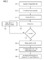
Das Verfahren geht in seinen beiden Ausführungsformen davon aus, dass an einem Patienten eine Katheterintervention vorgenommen wird, wobei sich der Patient hierbei im Röntgenangiographiesystem mit Röntgen-C-Bogen befindet. Bei einer Katheterintervention interessiert sich der behandelnde Arzt für die Herzkranzgefäße. Er nutzt das Röntgenangiographiesystem dazu, eine Mehrzahl von Röntgenbildern des Herzens gemäß Schritt S10 zu gewinnen, wobei im Regelfall auf einen Eingabebefehl hin das Röntgenangiographiesystem die Bildaufnahmeschritte selbständig durchführt. Der Röntgen-C-Bogen wird hierbei um seine Mittelachse gedreht, damit in unterschiedlichen Winkelstellungen bei dieser Bewegung Röntgenbilder aufgenommen werden. Der zeitliche Abstand zwischen der Aufnahme der einzelnen Röntgenbilder sollte zwischen 10 und 20 ms liegen, was bei der Aufnahme von insgesamt 400 Röntgenbildern über einen Winkelbereich von 200° möglich ist. Dann ändert sich die Lage der Herzkranzgefäße von Röntgenbild zu Röntgenbild kaum.In both embodiments, the method assumes that a catheter intervention is performed on a patient, whereby the patient is in the x-ray C-arm X-ray angiography system. In a catheter intervention, the attending physician is interested in the coronary arteries. He uses the X-ray angiography system to obtain a plurality of X-ray images of the heart according to step S10, whereby the X-ray angiography system normally performs the image recording steps independently upon an input command. The X-ray C-arm is rotated around its central axis so that X-ray images are recorded at different angular positions during this movement. The time interval between the recording of the individual X-ray images should be between 10 and 20 ms, which is possible when taking a total of 400 X-ray images over an angular range of 200 °. Then the position of the coronary arteries hardly changes from X-ray image to X-ray image.
In den einzelnen zweidimensionalen Röntgenbildern werden nun gemäß Schritt S12 die Herzkranzgefäße hervorgehoben. Dies kann eine einfache Filterung zur Erhöhung des Bildkontrastes beinhalten, bevorzugt wird das Verfahren der Segmentierung gemäß Koller et al, Frangi et al und gemäß Krissian et al verwendet, siehe die oben zitierten Artikel dieser Autoren.In the individual two-dimensional X-ray images, the coronary vessels are now highlighted according to step S12. This may involve simple filtering to increase the image contrast, preferably the method of segmentation according to Koller et al., Frangi et al and according to Krissian et al., See the above-cited articles of these authors.
Schritt S12 kann alternativ Teil der Aufnahme der Röntgenbilder sein, also z.B. implizit durch den Röntgenstrahlungsdetektor des Röntgenangiographiesystems aufgrund dessen Eigenschaften, die auf die Darstellung von Herzkranzgefäßen hin optimiert sein können, durchgeführt werden.Alternatively, step S12 may be part of the acquisition of the X-ray images, ie implicitly by the X-ray detector of the X-ray angiography system on the basis of its properties, which may be optimized for the presentation of coronary vessels.
Nun wird eine Funktion Φ(x, k) bestimmt. x ist hierbei ein Punkt im realen Raum, wobei der reale Raum auf das von dem Patienten eingenommene Raumvolumen beschränkt sein kann. k repräsentiert die Nummer des jeweiligen Röntgenbildes in der zeitlichen Reihenfolge seiner Aufnahme und entspricht der Zeit.Now a function Φ ( x , k) is determined. In this case, x is a point in real space, wherein the real space can be limited to the volume of space occupied by the patient. k represents the number of the respective X-ray image in the chronological order of its recording and corresponds to the time.
Die Funktion Φ hat im Folgenden die Aufgabe, die Zugehörigkeit bzw. Nichtzugehörigkeit von Raumpunkten, definiert zu den einzelnen Röntgenbildern, für die Herzkranzgefäße anzugeben. Bei den im Folgenden gegebenen Berechnungen wird davon ausgegangen, dass Φ(x) < 0 ist, wenn der Raumpunkt x innerhalb eines Herzkranzgefäßes zum Zeitpunkt der Aufnahme des Bildes k liegt. Der Wert Φ(x, k) ist größer als 0, wenn der Raumpunkt auf jeden Fall außerhalb der Herzkranzgefäße liegt, und er ist genau gleich 0, wenn er auf der Oberfläche eines Herzkranzgefäßes liegt.In the following, the function Φ has the task of indicating the affiliation or non-membership of spatial points, defined for the individual x-ray images, for the coronary vessels. In the calculations given below, it is assumed that Φ ( x ) <0 if the point in space x lies within a coronary vessel at the time the image k is taken. The value Φ ( x, k) is greater than 0 if the point in space is in any case outside the coronary vessels, and it is exactly 0 when it lies on the surface of a coronary vessel.
Wenn im Schritt S14 wird die Funktion Φ initialisiert worden ist, wird im Schritt S16 eine Größe E berechnet. Die Größe E soll wiedergeben inwieweit eine Zuordnung von Werten zu Φ(x, k) im dreidimensionalen Raum gemäß dem Röntgenbild von der Realität abweicht. Die Fehlergröße E setzt sich aus vier Teilgrößen E1, E2, E3 und E4 zusammen. E1 ist eine Teilgröße, die wiedergibt dass aufgrund der Zuordnung von Werten zu Φ fälschlicherweise Raumpunkten kein Herzkranzgefäß zugeordnet wird, auch wenn diese Raumpunkte auf einem Punkt im Röntgenbild abgebildet werden, der ein Herzkranzgefäß nach dem Hervorheben der Herzkranzgefäße in Schritt S12 zeigt. Die Teilgröße E2 gibt wieder, wie aufgrund der Zuordnung von Werten zu Φ fälschlicherweise Herzkranzgefäße im dreidimensionalen Raum vorgesehen sind, wo aufgrund des Röntgenbildes keine sein dürften. Die räumliche Veränderung der Größe Φ wird durch die Größe E3 angegeben, die Teilgröße E4 ist hier ein Maß für die zeitliche Veränderung von Röntgenbild zu Röntgenbild.If the function Φ has been initialized in step S14, a size E is calculated in step S16. The quantity E is intended to reflect to what extent an assignment of values to Φ ( x, k) in three-dimensional space deviates from reality in accordance with the X-ray image. The error variable E is composed of four sub-quantities E 1 , E 2 , E 3 and E 4 . E 1 is a fractional quantity representing that, due to the assignment of values to Φ, space dots are not assigned to a coronary vessel even though these space dots are imaged on a point in the X-ray image showing a coronary vessel after highlighting the coronary vessels in step S12. Partial size E 2 again shows how, due to the assignment of values to Φ, coronary vessels are erroneously provided in three-dimensional space, where due to the X-ray image none should be. The spatial variation of the size Φ is indicated by the size E 3 , the part size E 4 is here Measure for the temporal change from X-ray image to X-ray image.
Die Teilgröße E1 lässt sich wie folgt schreiben: 
E1 beinhaltet einen konstanten Faktor C1 und beinhaltet eine Summe über die Röntgenbilder k. Zu jedem Röntgenbild wird ein Integral über sämtliche Röntgenbildpunkte p berechnet, also über die Fläche des Röntgenstrahlungsdetektors. Zu jedem Punkt p ist die Intensität Ik(p) definiert. Diese wird in dem Integranden mit der Heavisidefunktion der folgenden Größe multipliziert:E 1 includes a constant factor C 1 and includes a sum over the X-ray images k. For each X-ray image, an integral over all X-ray pixels p is calculated, that is over the surface of the X-ray detector. For every point p the intensity I k ( p) is defined. This is multiplied in the integrand with the Heavisidefunktion of the following size:
Es wird zu jedem Punkt p die Gesamtheit X k(p) betrachtet, die sämtliche Raumpunkte beinhaltet, die auf dem Weg von der Röntgenquelle zum Punkt p aus dem Röntgenstrahlungsdetektor liegen. X k(p) ist also die Gesamtheit der Punkte auf dem Projektionsstrahl. Nun wird das Minimum von Φ(x,k) für alle auf diesem Strahl liegenden Raumpunkte x ermittelt, gegebenenfalls gibt es mehrere Minima. Ist das Minimum größer als 0, ergibt die Heavisidefunktion H den Wert 1. Daher gibt der Integrand einen Beitrag in Höhe von Ik(p). Es wird also die Intensität eines solchen Raumpunktes in der Teilgröße E1 gewichtet, wenn auf dem Strahl von der Röntgenstrahlungsquelle zu diesem Detektorenpunkt gemäß der Wertzuweisung zu Φ kein Herzkranzgefäß liegt. Die Intensität sollte so gestaltet sein, dass Ik(p) = 0, wenn das Röntgenbild tatsächlich kein Herzkranzgefäß zeigt. Liegt aber im k-ten Röntgenbild im Punkt p ein Herzkranzgefäß, so hat I einen Wert größer als 0, und dieser leistet eben gerade dann einen Beitrag zur Fehlergröße, wenn gemäß der Definition von Φ auf dem Strahlenweg zum Detektorenpunkt p kein Herzkranzgefäß liegen würde. Es wird also E1 umso größer, je mehr Detektorenpunkte p ein Herzkranzgefäß zeigen, zu denen gemäß den zugewiesenen Werten Φ kein Herzkranzgefäß im dreidimensionalen Raum gehören würde.For each point p, the totality X k ( p ) is considered, which includes all the points in space which lie on the way from the X-ray source to the point P from the X-ray detector. X k ( p ) is thus the totality of the points on the projection beam. Now the minimum of Φ ( x , k ) is determined for all spatial points x lying on this ray, if necessary there are several minima. If the minimum is greater than 0, the Heavisidefunktion H gives the value 1. Therefore, the integrand gives a contribution in the amount of I k ( p ). Thus, the intensity of such a spatial point in the subset E 1 is weighted if no coronary vessel is located on the beam from the X-ray source to this detector point according to the value assignment to Φ. The intensity should be such that I k ( p ) = 0 if the x-ray image does not actually show a coronary vessel. However, if a coronary vessel is located in the kth x-ray image at point p , I has a value greater than 0, and this just then contributes to the error size if, according to the definition of Φ, no coronary vessel would lie on the ray path to the detector point p . Thus, the greater the number of detector points p, the greater will be E 1 Show the coronary vessel to which, according to the assigned values Φ, no coronary vessel would belong in three-dimensional space.
Die Größe E2 ist wie folgt definiert: 
Die Größe E2 berechnet sich analog aus einem konstanten Faktor C2 mal der Summe über sämtliche Röntgenbilder. Zu jedem Röntgenbild wird ein Integral berechnet, vorliegend ein Volumenintegral über die Raumpunkte x. Der Integrand beinhaltet als Faktor die Größe 1 - H (Φ(x, k)). Ist Φ ein solcher Wert zugeordnet, dass von einem Herzkranzgefäß ausgegangen wird, so ist Φ < 0 und H (Φ) = 0. Dann ist 1 - H (Φ) = 1, und es ergibt sich ein Integrand von (1 - Ik(p k(x)). Hierbei ist p k(x) der Punkt auf den Röntgenstrahlungsdetektor, auf dem der Raumpunkt x projiziert wird. Ist Φ der korrekte Wert zugeordnet, so ist im Röntgenbild bei Φ < 0 ein hoher Wert von Ik zugeordnet, der sich normiert der Zahl 1 nähert. Dann leistet der Integrand fast keinen Beitrag. Im Falle eines Fehlers, dass aufgrund der Zuweisung des Wertes zu Φ fälschlicher Weise ein Herzkranzgefäß im dreidimensionalen Raum zugeordnet ist, das in dem Röntgenbild gar nicht gezeigt ist, ist Ik nahe an 0, und es ergibt sich ein relativ großer Beitrag im Integranden nahe an 1.The size E 2 is calculated analogously from a constant factor C 2 times the sum across all X-ray images. For each X-ray image, an integral is calculated, in the present case a volume integral over the spatial points x . The integrand contains the factor 1 - H (Φ ( x , k)) as a factor. If Φ is assigned such a value as to start from a coronary vessel, then Φ <0 and H (Φ) = 0. Then 1 - H (Φ) = 1, and the result is an integrand of (1 - I k (p k (x)). Here, p k (x) the point on the x-ray detector on which the spatial point x is projected. If associated with Φ the correct value, then in the x-ray image at Φ <0, a high value of I k then the integrand makes almost no contribution, in the case of an error that due to the assignment of the value to Φ is erroneously associated with a coronary vessel in three-dimensional space which is not shown in the x-ray image, I k is close to 0, and there is a relatively large contribution in the integrand close to 1.
Die Größe E3 lässt sich näherungsweise formulieren als: 
und die Größe E4 lässt sich näherungsweise formulieren als 
and the size E 4 can be approximated as
Es soll sich bei den Größen E3 und E4 jeweils um Funktionen der Ableitungen handeln, C3 und C4 sind hierbei Konstanten.The variables E 3 and E 4 should each be functions of the derivatives, C 3 and C 4 are constants.
So wie auch die Integrale aus E1 und E2 im Zweifel diskretisiert zu berechnen sind, sind vorliegend auch Näherungsverfahren für diese Ableitungen zu verwenden (Differenzquotient) bei ganzzahligen k. Es wird in Schritt S16 die Fehlergröße E als Summe E = E1 + E2 + E3 + E4 berechnet. Dadurch, dass E4 einbezogen wird, wird zu jedem Röntgenbild k eine Größe Φ definiert, bei der auch die zeitlich benachbart aufgenommenen Röntgenbilder berücksichtigt werden. Dadurch wird für eine zeitliche Stetigkeit in der späteren Darstellung gesorgt, die maßgeblich zur Qualität der später gewonnenen Darstellung beiträgt.Just as the integrals of E 1 and E 2 must be calculated discretized in doubt, in the present case approximation methods for these derivatives are also to be used (difference quotient) for integer k. In step S16, the error quantity E is calculated as the sum E = E 1 + E 2 + E 3 + E 4 . Because E 4 is included, a size Φ is defined for each X-ray image k, which also takes into account the temporally adjacent X-ray images. This ensures a temporal continuity in the later presentation, which contributes significantly to the quality of the later obtained representation.
Ihrem Namen entsprechend soll die Fehlergröße E möglichst klein sein. Im Schritt S18 wird daher geprüft, ob E minimal ist, und solange dies nicht der Fall ist, wird in Schritt S20 die Wertzuweisung für Φ geändert. Hierbei wird auf die Technik bekannter Variationsverfahren für Computerberechnungen geeigneter diskretisierter Form zurückgegriffen. Typischerweise wird hierbei Φ für jedes x und jedes k um einen Wert geändert, der von E, z.B. einer Ableitung von E, abhängig ist. Die Heavisidefunktion kann hierbei durch eine Funktion mit stetiger Ableitung z.B. eine Arcustangensfunktion, ersetzt werden.According to its name, the error size E should be as small as possible. In step S18, therefore, it is checked if E is minimum, and unless this is the case, the value assignment for Φ is changed in step S20. In this case, the technique of known variation methods for computer calculations of suitable discretized form is used. Typically, Φ is changed for each x and every k by a value that depends on E, eg a derivative of E. The Heavisidefunktion can be replaced by a function with a constant derivative such as an arctangent function.
Nach dem Ändern von Φ wird abermals die Fehlergröße in Schritt S16 ermittelt und nochmals in Schritt S18 geprüft, ob E nach einem vorbestimmten Kriterium minimal ist. Ist ein Abbruchkriterium erfüllt, dem gemäß E als minimal anzusehen ist, spiegeln die Wertzuweisungen für Φ die realen Raumstrukturen der Herzkranzgefäße des Patienten wieder. Φ = 0 ist hierbei die Definition der Oberfläche der Herzkranzgefäße mittels einer Niveaumenge. Das Verhältnis von Φ zu dieser, also Φ < 0 oder Φ > 0, bestimmt die Zugehörigkeit von Raumpunkten zu den Herzkranzgefäßen. Bei der Alternative gemäß
Bei einer zweiten Alternative des erfindungsgemäßen Verfahrens wird mehr als ein einfaches Schwarz-Weiß-Bild der Herzkranzgefäße geliefert. Hierzu wird, sobald die Wertzuteilung für Φ beendet ist, in S18 also erfasst wird, dass E gemäß vorbestimmtem Kriterium mimimal ist, aus den Werten von Φ in Schritt S26 ein Bewegungsfeld errechnet. Das Bewegungsfeld gibt wieder, wie sich einzelne Punkte auf der Oberfläche der Herzkranzgefäße im dreidimensionalen Raum von Röntgenbild zu Röntgenbild bewegt haben. Dann kann an bekannte Techniken angeknüpft werden, die Bewegungsfelder nutzen. Sind einmal Bewegungsfelder bekannt, kann eine 3D-Rekonstruktion errechnet werden. Es können auch aus Röntgenbildern, die in unterschiedlichen Herzschlagphasen aufgenommen werden, 3D-Rekonstruktionen gewonnen werden. Vorliegend wird somit in Schritt S28 eine 3D-Rekonstruktion der in Schritt S10 gewonnenen Röntgenbilder unter Verwendung der Bewegungsfelder errechnet. Anders als bei dem Verfahren, das anhand von
Die Erfindung verwendet eine rein abstrakt definierte Funktion Φ(x, k), um Volumenelemente im dreidimensionalen Raum Strukturen zuordnen zu können. Es kann dann eine Darstellung gegeben werden, bei der wie anhand von
Bei beiden Verfahren ist es sowohl möglich, ein einziges Bild für den Bildschirm zu errechnen, grundsätzlich aus beliebiger Perspektive. Genauso ist es möglich, eine Mehrzahl von Bildern auf der Grundlage jeweils eines Röntgenbildes zu errechnen und diese in der zeitlichen Abfolge der Aufnahmen der zugehörigen Röntgenbilder zu zeigen. Die Erfindung ermöglicht eine solche genaue Auflösung, dass auch Strukturen in der Größe von Herzkranzgefäßen deutlich sichtbar gemacht werden können, die dem behandelnden Arzt neue Möglichkeiten bei der Kontrolle von Katheterinterventionen eröffnen.In both methods, it is both possible to calculate a single image for the screen, basically from any perspective. In the same way, it is possible to calculate a plurality of images on the basis of an X-ray image in each case and to show them in the temporal sequence of the images of the associated X-ray images. The invention allows for such accurate resolution that also structures in the size of coronary vessels can be made clearly visible, opening up new possibilities for the doctor in the control of catheter interventions.
Claims (7)
Priority Applications (1)
| Application Number | Priority Date | Filing Date | Title |
|---|---|---|---|
| EP09151074A EP2187353B1 (en) | 2008-11-10 | 2009-01-22 | Method for visualising structures in a body, in particular in the body of a patient |
Applications Claiming Priority (3)
| Application Number | Priority Date | Filing Date | Title |
|---|---|---|---|
| EP08019641 | 2008-11-10 | ||
| EP08019642 | 2008-11-10 | ||
| EP09151074A EP2187353B1 (en) | 2008-11-10 | 2009-01-22 | Method for visualising structures in a body, in particular in the body of a patient |
Publications (3)
| Publication Number | Publication Date |
|---|---|
| EP2187353A2 true EP2187353A2 (en) | 2010-05-19 |
| EP2187353A3 EP2187353A3 (en) | 2010-06-23 |
| EP2187353B1 EP2187353B1 (en) | 2011-10-19 |
Family
ID=40383800
Family Applications (1)
| Application Number | Title | Priority Date | Filing Date |
|---|---|---|---|
| EP09151074A Not-in-force EP2187353B1 (en) | 2008-11-10 | 2009-01-22 | Method for visualising structures in a body, in particular in the body of a patient |
Country Status (2)
| Country | Link |
|---|---|
| EP (1) | EP2187353B1 (en) |
| AT (1) | ATE529839T1 (en) |
Cited By (1)
| Publication number | Priority date | Publication date | Assignee | Title |
|---|---|---|---|---|
| US9675304B2 (en) | 2011-06-27 | 2017-06-13 | Koninklijke Philips N.V. | Live 3D angiogram using registration of a surgical tool curve to an X-ray image |
Citations (1)
| Publication number | Priority date | Publication date | Assignee | Title |
|---|---|---|---|---|
| US20060133564A1 (en) | 2004-12-21 | 2006-06-22 | David Langan | Method and apparatus for correcting motion in image reconstruction |
-
2009
- 2009-01-22 AT AT09151074T patent/ATE529839T1/en active
- 2009-01-22 EP EP09151074A patent/EP2187353B1/en not_active Not-in-force
Patent Citations (1)
| Publication number | Priority date | Publication date | Assignee | Title |
|---|---|---|---|---|
| US20060133564A1 (en) | 2004-12-21 | 2006-06-22 | David Langan | Method and apparatus for correcting motion in image reconstruction |
Non-Patent Citations (8)
| Title |
|---|
| ALEJANDRO F. FRANGI; WIRO J. NIESSEN; KOEN L. VINCKEN; MAX A. VIERGEVER: "Proc. Int'l Conf. Med. Image Computing and Computer Assisted Intervention (MICCAI)", vol. 1496, SPRINGER, article "Multiscale vessel enhancement filtering", pages: 130 - 137 |
| GÜNTER LAURITSCH; JAN BOESE; LARS WIGSTRÖM; HERBERT KENNETH; REBECCA FAHRIG: "Towards cardiac C-arm computed tomography", IEEE TRANS. MED. IMAG., vol. 25, no. 7, 2006, pages 922 - 934 |
| KARL KRISSIAN; GREGOIRE MALANDAIN; NICHOLAS AYACHE; REGIS VAILLANT; YVES TROUSSET: "Model-based detection of tubular structures in 3D images", J. COMP. VIS. AND IMG. UNDERSTANDING, vol. 80, no. 2, 2000, pages 130 - 171, Retrieved from the Internet <URL:http: //dx.doi.org/10. 1006/cviu.2000.0866> |
| M. STYNER ET AL.: "Efficient segmentation of 3D fluoroskopic datasets from mobile C-arm", PROCEEDINGS OF THE SPIE - THE INTERNATIONAL SOCIETY FOR OPTICAL ENGINEERING, SPIE, US, vol. 5370, no. 1, 16 February 2004 (2004-02-16), pages 1667 - 1678 |
| MARCUS PRÜMMER; LARS WIGSTROEM; JOACHIM HORNEGGER; JAN BOESE; GUENTER LAURITSCH; NORBERT STROBEL; REBECCA FAHRIG: "Nuclear Science Symposium, Medical Imaging Conference", November 2006, SPRINGER, article "Cardiac C-arm CT: Efficient motion correction for 4D-FBP", pages: 1 - 20 |
| QI SU ET AL.: "A Semi-Automatic Clustering-Based Level Set Method for Segmentation of Endocardium from MSCT Images", ENGINEERING IN MEDICINE AND BIOLOGY SOCIETY, 2007. EMBS 2007, 29' ANNUAL INTERNATIONAL CONFERENCE OF THE IEEE, IEEE, 22 August 2007 (2007-08-22), pages 6023 - 6026 |
| T. KOHLBERGER ET AL.: "MEDICAL IMAGE COMPUTING AND COMPUTER-ASSISTED INTERVENTION - MIC CAI 2006 LECTURE NOTES IN COMPUTER SCIENCES", 1 January 2006, SPRINGER, article "4D shape Priors for a Level Set Segmentation of the Left Myocardium in SPECT Sequences", pages: 92 - 100 |
| T.M. KOLLER; G. GERIG; GABOR SZEKELY; D. DETT WILER: "Multiscale detection of curvilinear structures in 2-D und 3-D image data", PROC. INT'L CONF. COMP. VIS (ICCV), June 1995 (1995-06-01), pages 864 - 869, Retrieved from the Internet <URL:http://dx.doi.org/10.1109/ICCV. 1995. 466846> |
Cited By (1)
| Publication number | Priority date | Publication date | Assignee | Title |
|---|---|---|---|---|
| US9675304B2 (en) | 2011-06-27 | 2017-06-13 | Koninklijke Philips N.V. | Live 3D angiogram using registration of a surgical tool curve to an X-ray image |
Also Published As
| Publication number | Publication date |
|---|---|
| ATE529839T1 (en) | 2011-11-15 |
| EP2187353B1 (en) | 2011-10-19 |
| EP2187353A3 (en) | 2010-06-23 |
Similar Documents
| Publication | Publication Date | Title |
|---|---|---|
| DE602004002939T2 (en) | METHOD FOR THE THREE-DIMENSIONAL MODELING OF TUBULAR STRUCTURES | |
| DE102006045423B4 (en) | 07.09.07 Method for postprocessing a three-dimensional image data set of a vessel structure | |
| DE102005027963B3 (en) | Method of reconstructing three dimensional image data set of moved object from set of projected images taken from different directions involves dividing images into several partial sets taken during given phases of object movement | |
| DE102012207629B4 (en) | CT image reconstruction in the extended measuring field | |
| DE102011087337B4 (en) | A method of reconstructing a reconstruction data set containing two-dimensional virtual X-ray images | |
| DE10129631A1 (en) | Process for the reconstruction of a high-resolution 3D image | |
| DE10100572A1 (en) | Method for displaying blood flow in a vascular tree | |
| DE102009051384A1 (en) | Beam hardening correction for CT perfusion measurements | |
| DE102010034099B4 (en) | Iterative image filtering with anisotropic noise model for a CT image | |
| DE102009014723A1 (en) | Contrast-dependent regularization strength in the iterative reconstruction of CT images | |
| DE102016219887A1 (en) | Method and system for using measured data | |
| DE102011083647A1 (en) | Motion compensated computer tomography-image data set creating method, involves reconstructing final image data set using movement-compensating reconstruction method based on reconstruction algorithm and movement field | |
| DE102012209410A1 (en) | Determination of a patient-specific contrast agent impulse response function | |
| DE102012104599A1 (en) | Method and system for the reconstruction of tomographic images | |
| DE102010013360B4 (en) | Method for reconstructing image data of a cyclically moving examination object | |
| DE102008048045A1 (en) | A method for generating computer tomographic image data sets of a patient in cardiac CT in a perfusion control under contrast medium application | |
| DE102007045313B4 (en) | Method for the separate three-dimensional representation of arteries and veins in an examination subject | |
| DE102006045721A1 (en) | Tomographic photograph production method for partially cyclically moved test subject involves utilizing data records from detector output data of different cycle phase ranges in each of at least two iteration stages | |
| DE102010062975B4 (en) | Method for generating a four-dimensional representation of a target area of a body subject to periodic movement | |
| DE102008038357B3 (en) | Method for generating 2D slice images from 3D projection data acquired by means of a CT system from an examination object containing metallic parts | |
| DE102009007236A1 (en) | CT image reconstruction of a moving examination object | |
| DE10018707A1 (en) | Image reconfiguration apparatus for tomosynthesis in computerized tomography, produces reconfiguration algorithm based on virtual pixel weightages obtained by extrapolation of projection data | |
| DE102006002895B3 (en) | Cardio computer tomography display generation method for patient`s heart, involves reconstructing heart phase representation of each Roentgen spectrum with demand interval, and generating combined representation from result of scans | |
| EP2187353B1 (en) | Method for visualising structures in a body, in particular in the body of a patient | |
| DE102009021521B4 (en) | Method for the motion-compensated reconstruction of a three-dimensional image data set and X-ray device |
Legal Events
| Date | Code | Title | Description |
|---|---|---|---|
| PUAI | Public reference made under article 153(3) epc to a published international application that has entered the european phase |
Free format text: ORIGINAL CODE: 0009012 |
|
| AK | Designated contracting states |
Kind code of ref document: A2 Designated state(s): AT BE BG CH CY CZ DE DK EE ES FI FR GB GR HR HU IE IS IT LI LT LU LV MC MK MT NL NO PL PT RO SE SI SK TR |
|
| AX | Request for extension of the european patent |
Extension state: AL BA RS |
|
| PUAL | Search report despatched |
Free format text: ORIGINAL CODE: 0009013 |
|
| AK | Designated contracting states |
Kind code of ref document: A3 Designated state(s): AT BE BG CH CY CZ DE DK EE ES FI FR GB GR HR HU IE IS IT LI LT LU LV MC MK MT NL NO PL PT RO SE SI SK TR |
|
| AX | Request for extension of the european patent |
Extension state: AL BA RS |
|
| 17P | Request for examination filed |
Effective date: 20101018 |
|
| 17Q | First examination report despatched |
Effective date: 20101215 |
|
| AKX | Designation fees paid |
Designated state(s): AT BE BG CH CY CZ DE DK EE ES FI FR GB GR HR HU IE IS IT LI LT LU LV MC MK MT NL NO PL PT RO SE SI SK TR |
|
| GRAP | Despatch of communication of intention to grant a patent |
Free format text: ORIGINAL CODE: EPIDOSNIGR1 |
|
| GRAS | Grant fee paid |
Free format text: ORIGINAL CODE: EPIDOSNIGR3 |
|
| GRAA | (expected) grant |
Free format text: ORIGINAL CODE: 0009210 |
|
| AK | Designated contracting states |
Kind code of ref document: B1 Designated state(s): AT BE BG CH CY CZ DE DK EE ES FI FR GB GR HR HU IE IS IT LI LT LU LV MC MK MT NL NO PL PT RO SE SI SK TR |
|
| REG | Reference to a national code |
Ref country code: GB Ref legal event code: FG4D Free format text: NOT ENGLISH |
|
| REG | Reference to a national code |
Ref country code: CH Ref legal event code: EP |
|
| REG | Reference to a national code |
Ref country code: IE Ref legal event code: FG4D |
|
| REG | Reference to a national code |
Ref country code: DE Ref legal event code: R096 Ref document number: 502009001625 Country of ref document: DE Effective date: 20120119 |
|
| REG | Reference to a national code |
Ref country code: NL Ref legal event code: VDEP Effective date: 20111019 |
|
| LTIE | Lt: invalidation of european patent or patent extension |
Effective date: 20111019 |
|
| PG25 | Lapsed in a contracting state [announced via postgrant information from national office to epo] |
Ref country code: IS Free format text: LAPSE BECAUSE OF FAILURE TO SUBMIT A TRANSLATION OF THE DESCRIPTION OR TO PAY THE FEE WITHIN THE PRESCRIBED TIME-LIMIT Effective date: 20120219 Ref country code: NO Free format text: LAPSE BECAUSE OF FAILURE TO SUBMIT A TRANSLATION OF THE DESCRIPTION OR TO PAY THE FEE WITHIN THE PRESCRIBED TIME-LIMIT Effective date: 20120119 Ref country code: LT Free format text: LAPSE BECAUSE OF FAILURE TO SUBMIT A TRANSLATION OF THE DESCRIPTION OR TO PAY THE FEE WITHIN THE PRESCRIBED TIME-LIMIT Effective date: 20111019 |
|
| REG | Reference to a national code |
Ref country code: IE Ref legal event code: FD4D |
|
| PG25 | Lapsed in a contracting state [announced via postgrant information from national office to epo] |
Ref country code: SI Free format text: LAPSE BECAUSE OF FAILURE TO SUBMIT A TRANSLATION OF THE DESCRIPTION OR TO PAY THE FEE WITHIN THE PRESCRIBED TIME-LIMIT Effective date: 20111019 Ref country code: PT Free format text: LAPSE BECAUSE OF FAILURE TO SUBMIT A TRANSLATION OF THE DESCRIPTION OR TO PAY THE FEE WITHIN THE PRESCRIBED TIME-LIMIT Effective date: 20120220 Ref country code: GR Free format text: LAPSE BECAUSE OF FAILURE TO SUBMIT A TRANSLATION OF THE DESCRIPTION OR TO PAY THE FEE WITHIN THE PRESCRIBED TIME-LIMIT Effective date: 20120120 Ref country code: NL Free format text: LAPSE BECAUSE OF FAILURE TO SUBMIT A TRANSLATION OF THE DESCRIPTION OR TO PAY THE FEE WITHIN THE PRESCRIBED TIME-LIMIT Effective date: 20111019 Ref country code: SE Free format text: LAPSE BECAUSE OF FAILURE TO SUBMIT A TRANSLATION OF THE DESCRIPTION OR TO PAY THE FEE WITHIN THE PRESCRIBED TIME-LIMIT Effective date: 20111019 Ref country code: LV Free format text: LAPSE BECAUSE OF FAILURE TO SUBMIT A TRANSLATION OF THE DESCRIPTION OR TO PAY THE FEE WITHIN THE PRESCRIBED TIME-LIMIT Effective date: 20111019 Ref country code: HR Free format text: LAPSE BECAUSE OF FAILURE TO SUBMIT A TRANSLATION OF THE DESCRIPTION OR TO PAY THE FEE WITHIN THE PRESCRIBED TIME-LIMIT Effective date: 20111019 |
|
| PG25 | Lapsed in a contracting state [announced via postgrant information from national office to epo] |
Ref country code: CY Free format text: LAPSE BECAUSE OF FAILURE TO SUBMIT A TRANSLATION OF THE DESCRIPTION OR TO PAY THE FEE WITHIN THE PRESCRIBED TIME-LIMIT Effective date: 20111019 |
|
| BERE | Be: lapsed |
Owner name: SIEMENS A.G. Effective date: 20120131 |
|
| PG25 | Lapsed in a contracting state [announced via postgrant information from national office to epo] |
Ref country code: BG Free format text: LAPSE BECAUSE OF FAILURE TO SUBMIT A TRANSLATION OF THE DESCRIPTION OR TO PAY THE FEE WITHIN THE PRESCRIBED TIME-LIMIT Effective date: 20120119 Ref country code: EE Free format text: LAPSE BECAUSE OF FAILURE TO SUBMIT A TRANSLATION OF THE DESCRIPTION OR TO PAY THE FEE WITHIN THE PRESCRIBED TIME-LIMIT Effective date: 20111019 Ref country code: SK Free format text: LAPSE BECAUSE OF FAILURE TO SUBMIT A TRANSLATION OF THE DESCRIPTION OR TO PAY THE FEE WITHIN THE PRESCRIBED TIME-LIMIT Effective date: 20111019 Ref country code: DK Free format text: LAPSE BECAUSE OF FAILURE TO SUBMIT A TRANSLATION OF THE DESCRIPTION OR TO PAY THE FEE WITHIN THE PRESCRIBED TIME-LIMIT Effective date: 20111019 Ref country code: CZ Free format text: LAPSE BECAUSE OF FAILURE TO SUBMIT A TRANSLATION OF THE DESCRIPTION OR TO PAY THE FEE WITHIN THE PRESCRIBED TIME-LIMIT Effective date: 20111019 Ref country code: IE Free format text: LAPSE BECAUSE OF FAILURE TO SUBMIT A TRANSLATION OF THE DESCRIPTION OR TO PAY THE FEE WITHIN THE PRESCRIBED TIME-LIMIT Effective date: 20111019 |
|
| PLBE | No opposition filed within time limit |
Free format text: ORIGINAL CODE: 0009261 |
|
| STAA | Information on the status of an ep patent application or granted ep patent |
Free format text: STATUS: NO OPPOSITION FILED WITHIN TIME LIMIT |
|
| PG25 | Lapsed in a contracting state [announced via postgrant information from national office to epo] |
Ref country code: IT Free format text: LAPSE BECAUSE OF FAILURE TO SUBMIT A TRANSLATION OF THE DESCRIPTION OR TO PAY THE FEE WITHIN THE PRESCRIBED TIME-LIMIT Effective date: 20111019 Ref country code: RO Free format text: LAPSE BECAUSE OF FAILURE TO SUBMIT A TRANSLATION OF THE DESCRIPTION OR TO PAY THE FEE WITHIN THE PRESCRIBED TIME-LIMIT Effective date: 20111019 Ref country code: PL Free format text: LAPSE BECAUSE OF FAILURE TO SUBMIT A TRANSLATION OF THE DESCRIPTION OR TO PAY THE FEE WITHIN THE PRESCRIBED TIME-LIMIT Effective date: 20111019 Ref country code: MC Free format text: LAPSE BECAUSE OF NON-PAYMENT OF DUE FEES Effective date: 20120131 |
|
| 26N | No opposition filed |
Effective date: 20120720 |
|
| REG | Reference to a national code |
Ref country code: FR Ref legal event code: ST Effective date: 20120928 |
|
| REG | Reference to a national code |
Ref country code: DE Ref legal event code: R097 Ref document number: 502009001625 Country of ref document: DE Effective date: 20120720 |
|
| PG25 | Lapsed in a contracting state [announced via postgrant information from national office to epo] |
Ref country code: BE Free format text: LAPSE BECAUSE OF NON-PAYMENT OF DUE FEES Effective date: 20120131 Ref country code: FR Free format text: LAPSE BECAUSE OF NON-PAYMENT OF DUE FEES Effective date: 20120131 |
|
| PG25 | Lapsed in a contracting state [announced via postgrant information from national office to epo] |
Ref country code: MK Free format text: LAPSE BECAUSE OF FAILURE TO SUBMIT A TRANSLATION OF THE DESCRIPTION OR TO PAY THE FEE WITHIN THE PRESCRIBED TIME-LIMIT Effective date: 20111019 |
|
| PG25 | Lapsed in a contracting state [announced via postgrant information from national office to epo] |
Ref country code: ES Free format text: LAPSE BECAUSE OF FAILURE TO SUBMIT A TRANSLATION OF THE DESCRIPTION OR TO PAY THE FEE WITHIN THE PRESCRIBED TIME-LIMIT Effective date: 20120130 |
|
| PG25 | Lapsed in a contracting state [announced via postgrant information from national office to epo] |
Ref country code: FI Free format text: LAPSE BECAUSE OF FAILURE TO SUBMIT A TRANSLATION OF THE DESCRIPTION OR TO PAY THE FEE WITHIN THE PRESCRIBED TIME-LIMIT Effective date: 20111019 |
|
| PG25 | Lapsed in a contracting state [announced via postgrant information from national office to epo] |
Ref country code: MT Free format text: LAPSE BECAUSE OF FAILURE TO SUBMIT A TRANSLATION OF THE DESCRIPTION OR TO PAY THE FEE WITHIN THE PRESCRIBED TIME-LIMIT Effective date: 20111019 |
|
| REG | Reference to a national code |
Ref country code: CH Ref legal event code: PL |
|
| GBPC | Gb: european patent ceased through non-payment of renewal fee |
Effective date: 20130122 |
|
| PG25 | Lapsed in a contracting state [announced via postgrant information from national office to epo] |
Ref country code: CH Free format text: LAPSE BECAUSE OF NON-PAYMENT OF DUE FEES Effective date: 20130131 Ref country code: LI Free format text: LAPSE BECAUSE OF NON-PAYMENT OF DUE FEES Effective date: 20130131 |
|
| PG25 | Lapsed in a contracting state [announced via postgrant information from national office to epo] |
Ref country code: GB Free format text: LAPSE BECAUSE OF NON-PAYMENT OF DUE FEES Effective date: 20130122 |
|
| PG25 | Lapsed in a contracting state [announced via postgrant information from national office to epo] |
Ref country code: TR Free format text: LAPSE BECAUSE OF FAILURE TO SUBMIT A TRANSLATION OF THE DESCRIPTION OR TO PAY THE FEE WITHIN THE PRESCRIBED TIME-LIMIT Effective date: 20111019 |
|
| PG25 | Lapsed in a contracting state [announced via postgrant information from national office to epo] |
Ref country code: LU Free format text: LAPSE BECAUSE OF NON-PAYMENT OF DUE FEES Effective date: 20120122 |
|
| PG25 | Lapsed in a contracting state [announced via postgrant information from national office to epo] |
Ref country code: HU Free format text: LAPSE BECAUSE OF FAILURE TO SUBMIT A TRANSLATION OF THE DESCRIPTION OR TO PAY THE FEE WITHIN THE PRESCRIBED TIME-LIMIT Effective date: 20090122 |
|
| REG | Reference to a national code |
Ref country code: AT Ref legal event code: MM01 Ref document number: 529839 Country of ref document: AT Kind code of ref document: T Effective date: 20140122 |
|
| PG25 | Lapsed in a contracting state [announced via postgrant information from national office to epo] |
Ref country code: AT Free format text: LAPSE BECAUSE OF NON-PAYMENT OF DUE FEES Effective date: 20140122 |
|
| REG | Reference to a national code |
Ref country code: DE Ref legal event code: R081 Ref document number: 502009001625 Country of ref document: DE Owner name: SIEMENS HEALTHCARE GMBH, DE Free format text: FORMER OWNER: SIEMENS AKTIENGESELLSCHAFT, 80333 MUENCHEN, DE |
|
| PGFP | Annual fee paid to national office [announced via postgrant information from national office to epo] |
Ref country code: DE Payment date: 20190319 Year of fee payment: 11 |
|
| REG | Reference to a national code |
Ref country code: DE Ref legal event code: R119 Ref document number: 502009001625 Country of ref document: DE |
|
| PG25 | Lapsed in a contracting state [announced via postgrant information from national office to epo] |
Ref country code: DE Free format text: LAPSE BECAUSE OF NON-PAYMENT OF DUE FEES Effective date: 20200801 |