EP2181780A1 - Pipe-bending machine having an improved movement transmission to a bending die - Google Patents
Pipe-bending machine having an improved movement transmission to a bending die Download PDFInfo
- Publication number
- EP2181780A1 EP2181780A1 EP09425420A EP09425420A EP2181780A1 EP 2181780 A1 EP2181780 A1 EP 2181780A1 EP 09425420 A EP09425420 A EP 09425420A EP 09425420 A EP09425420 A EP 09425420A EP 2181780 A1 EP2181780 A1 EP 2181780A1
- Authority
- EP
- European Patent Office
- Prior art keywords
- machine
- gear wheel
- pipe
- bending die
- bending
- Prior art date
- Legal status (The legal status is an assumption and is not a legal conclusion. Google has not performed a legal analysis and makes no representation as to the accuracy of the status listed.)
- Granted
Links
- 238000005452 bending Methods 0.000 title claims abstract description 37
- 230000005540 biological transmission Effects 0.000 title claims abstract description 10
- 238000005259 measurement Methods 0.000 description 1
Images


Classifications
-
- B—PERFORMING OPERATIONS; TRANSPORTING
- B21—MECHANICAL METAL-WORKING WITHOUT ESSENTIALLY REMOVING MATERIAL; PUNCHING METAL
- B21D—WORKING OR PROCESSING OF SHEET METAL OR METAL TUBES, RODS OR PROFILES WITHOUT ESSENTIALLY REMOVING MATERIAL; PUNCHING METAL
- B21D7/00—Bending rods, profiles, or tubes
- B21D7/04—Bending rods, profiles, or tubes over a movably-arranged forming menber
-
- B—PERFORMING OPERATIONS; TRANSPORTING
- B21—MECHANICAL METAL-WORKING WITHOUT ESSENTIALLY REMOVING MATERIAL; PUNCHING METAL
- B21D—WORKING OR PROCESSING OF SHEET METAL OR METAL TUBES, RODS OR PROFILES WITHOUT ESSENTIALLY REMOVING MATERIAL; PUNCHING METAL
- B21D7/00—Bending rods, profiles, or tubes
- B21D7/02—Bending rods, profiles, or tubes over a stationary forming member; by use of a swinging forming member or abutment
- B21D7/024—Bending rods, profiles, or tubes over a stationary forming member; by use of a swinging forming member or abutment by a swinging forming member
-
- B—PERFORMING OPERATIONS; TRANSPORTING
- B21—MECHANICAL METAL-WORKING WITHOUT ESSENTIALLY REMOVING MATERIAL; PUNCHING METAL
- B21D—WORKING OR PROCESSING OF SHEET METAL OR METAL TUBES, RODS OR PROFILES WITHOUT ESSENTIALLY REMOVING MATERIAL; PUNCHING METAL
- B21D7/00—Bending rods, profiles, or tubes
- B21D7/02—Bending rods, profiles, or tubes over a stationary forming member; by use of a swinging forming member or abutment
Definitions
- the present invention relates to a pipe bending machine having an improved movement transmission to a bending die.
- the machine comprises a body and a head. Housed in the body is a motor, whose output shaft supports a driving gear wheel in the machine head. The driving gear wheel engages a driven gear wheel that is rigidly connected to a pipe bending die. It is evident that greater is the diameter of the pipes to be bent, higher is the required motor power, and also the transmission gear wheels must be suitable to the required torque. Increased required torque needs increased sizes of the machine, and as a result also the cost of the machine rises.
- the technical problem at the basis of the present invention is to provide a pipe bending machine having an improved movement transmission to a bending die in order to overcome above cited drawbacks relating to the encumbrance and low transmitted power in the state of art.
- an object of the present invention is to provide a pipe bending machine having an improved movement transmission to a bending die, the pipe bending machine having reduced-size gear wheels maintaining the same power transmitted from the driving gear wheel to the driven gear wheel.
- a pipe bending machine having an improved movement transmission to a bending die, the machine comprising a body and a head, a motor being housed in the machine body and having an output shaft supporting a driving gear wheel, which is located in the machine head, and a driven gear wheel, which is connected to a pipe bending die, being located in the same machine head, wherein a couple of intermediate gear wheels engage both the driving gear wheel and the driven gear wheel.
- the Applicant developed a so called translation invention, transposing a device from a technical field, where said device is already known, to another one in which the device is not yet employed.
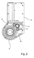
- a machine body is indicated as 1 and a machine head as 2.
- a motor 3 generally an electric motor.
- a driving gear wheel 5 is keyed to the output shaft 4 of the motor 3.
- Located on the machine head 2 is also a bending die 6 (only partially shown) that allows pipes to be bent in a known way.
- the bending die 6 is rotated by a shaft 7 to which a driven gear wheel 8 is keyed.
- intermediate gear wheels 9 and 10 are interposed between the driving gear wheel 5 and the driven gear wheel 8.
- the intermediate gear wheels 9 and 10 engage at the same time both the driving gear wheel 5 and the driven gear wheel 8. In such a way the intermediate gear wheels 9 and 10 both transmit a movement of rotation from the driving gear wheel 5. If the driving gear wheel rotates in a direction, also the driven gear wheel 8 rotates in the same direction.
- the power transmitted from the motor 3 to the bending die 6 being equal, the size of the gear wheels of the transmission and then of the machine head 2, and generally of all pipe bending machine, can be reduced.
- FIG. 3 shown therein is a general axonometric view of the pipe bending machine in which the present invention is embodied.
- the sizes of the machine being equal to those of the precedent machines having a reduced performance, to develop improved bending performance, up to the double of the present one, is made easier.
Abstract
Description
- The present invention relates to a pipe bending machine having an improved movement transmission to a bending die.
- In the existing pipe bending machines the machine comprises a body and a head. Housed in the body is a motor, whose output shaft supports a driving gear wheel in the machine head. The driving gear wheel engages a driven gear wheel that is rigidly connected to a pipe bending die. It is evident that greater is the diameter of the pipes to be bent, higher is the required motor power, and also the transmission gear wheels must be suitable to the required torque. Increased required torque needs increased sizes of the machine, and as a result also the cost of the machine rises.
-
U.S. Patents Nos. 3,302,505 and5,709,144 in the name of Shiokawa both relate to a machine press characterised by being small in size but producing a high pressure. Among the solutions chosen by that inventor for achieving his objects, provision is made that the power is transmitted from a driving gear wheel to a driven gear wheel by interposing a couple of idle pinion gears between said gear wheels. Whereby, as said in those patents, "the force conveyed by the rotation is doubled, so that the diameter of the gear wheel can be reduced by half. As the result, it becomes possible to reduce the measurements of the machine by placing all the gears in the frame and also to reduce the wear and noise of each part". - According to the present invention, what is taught with reference to a machine press is thought to be transferred to another kind of machine, such as a pipe bender, taking the same solution with the purpose of obtaining either reduced sizes or, alternatively, an improved performance of the pipe bending machine.
- In this context, the technical problem at the basis of the present invention is to provide a pipe bending machine having an improved movement transmission to a bending die in order to overcome above cited drawbacks relating to the encumbrance and low transmitted power in the state of art.
- In particular, an object of the present invention is to provide a pipe bending machine having an improved movement transmission to a bending die, the pipe bending machine having reduced-size gear wheels maintaining the same power transmitted from the driving gear wheel to the driven gear wheel.
- The object is generally achieved by a pipe bending machine having an improved movement transmission to a bending die, the machine comprising a body and a head, a motor being housed in the machine body and having an output shaft supporting a driving gear wheel, which is located in the machine head, and a driven gear wheel, which is connected to a pipe bending die, being located in the same machine head, wherein a couple of intermediate gear wheels engage both the driving gear wheel and the driven gear wheel.
- As one can see, the Applicant developed a so called translation invention, transposing a device from a technical field, where said device is already known, to another one in which the device is not yet employed.
- Further features and advantages of the present invention will be more evident by a schematic and therefore not limiting description of an embodiment of a pipe bending machine having an improved movement transmission to a bending die as shown in the accompanying drawings in which:
-
figure 1 is a cut axonometric view, with some parts being removed, of a pipe bending machine according to the invention; -
figure 2 is a partially cut top plan view of the pipe bending machine infigure 1 , with the bending die being removed; and -
figure 3 is a general axonometric view of the pipe bending machine according to the invention, with a pipe ready to be bent. - First referring to the axonometric view in
figure 1 , therein a machine body is indicated as 1 and a machine head as 2. Conventionally, situated inside the machine body is amotor 3, generally an electric motor. Adriving gear wheel 5 is keyed to theoutput shaft 4 of themotor 3. Located on themachine head 2 is also a bending die 6 (only partially shown) that allows pipes to be bent in a known way. Thebending die 6 is rotated by ashaft 7 to which a drivengear wheel 8 is keyed. According to the present invention, as best shown in the top plan view of the pipe bending machine infigure 2 (with the bending die being removed),intermediate gear wheels driving gear wheel 5 and the drivengear wheel 8. Theintermediate gear wheels driving gear wheel 5 and the drivengear wheel 8. In such a way theintermediate gear wheels driving gear wheel 5. If the driving gear wheel rotates in a direction, also the drivengear wheel 8 rotates in the same direction. - Thanks to the present invention, the power transmitted from the
motor 3 to thebending die 6 being equal, the size of the gear wheels of the transmission and then of themachine head 2, and generally of all pipe bending machine, can be reduced. - With reference to
figure 3 shown therein is a general axonometric view of the pipe bending machine in which the present invention is embodied. A pipe T that is positioned between the bending die 6 and the counter bending die 11, ready to be bent, is therein shown. - Thanks to the present invention, the sizes of the machine being equal to those of the precedent machines having a reduced performance, to develop improved bending performance, up to the double of the present one, is made easier.
Claims (1)
- A pipe bending machine having an improved movement transmission to a bending die, said machine comprising a body (1) and a head (2), a motor (3) being housed in the machine body (1) and having an output shaft (4) supporting a driving gear wheel (5), which is located in the machine head (2), and a driven gear wheel (8), which is connected to a pipe bending die (6), being located in the same machine head (2), characterised in that a couple of intermediate gear wheels (9, 10) engage both the driving gear wheel (5) and the driven gear wheel (8).
Applications Claiming Priority (1)
| Application Number | Priority Date | Filing Date | Title |
|---|---|---|---|
| ITRM2008A000574A IT1391476B1 (en) | 2008-10-28 | 2008-10-28 | CURVATURI MACHINE WITH PERFECT TRANSMISSION OF THE MOTORCYCLE TO THE MATRIX |
Publications (2)
| Publication Number | Publication Date |
|---|---|
| EP2181780A1 true EP2181780A1 (en) | 2010-05-05 |
| EP2181780B1 EP2181780B1 (en) | 2011-06-15 |
Family
ID=41137356
Family Applications (1)
| Application Number | Title | Priority Date | Filing Date |
|---|---|---|---|
| EP09425420A Active EP2181780B1 (en) | 2008-10-28 | 2009-10-23 | Pipe-bending machine having an improved movement transmission to a bending die |
Country Status (10)
| Country | Link |
|---|---|
| US (1) | US20100101299A1 (en) |
| EP (1) | EP2181780B1 (en) |
| JP (1) | JP2010105047A (en) |
| KR (1) | KR20100047144A (en) |
| CN (1) | CN101722216A (en) |
| AT (1) | ATE512732T1 (en) |
| BR (1) | BRPI0904398A2 (en) |
| ES (1) | ES2368196T3 (en) |
| IT (1) | IT1391476B1 (en) |
| RU (1) | RU2431534C2 (en) |
Cited By (6)
| Publication number | Priority date | Publication date | Assignee | Title |
|---|---|---|---|---|
| CN102343384A (en) * | 2011-10-16 | 2012-02-08 | 上海国青机械有限公司 | Dual-power-driven digital control pipe bender |
| CN103406406A (en) * | 2013-07-16 | 2013-11-27 | 和和机械(张家港)有限公司 | Rotary mould structure of pipe bending machine |
| CN103567262A (en) * | 2012-08-07 | 2014-02-12 | 浙江摩多巴克斯汽配有限公司 | Machine head of pipe bending machine |
| ITRM20120618A1 (en) * | 2012-12-06 | 2014-06-07 | Libero Angelo Massaro | MODULAR MACHINE, FOR BENDING METAL TUBES. |
| EP2995393A1 (en) | 2014-09-11 | 2016-03-16 | Melchor Gabilondo, S.A. | Bending machine |
| CN111842574A (en) * | 2020-07-23 | 2020-10-30 | 临海市金源工艺品有限公司 | A equipment of buckling for producing rattan chair skeleton |
Families Citing this family (14)
| Publication number | Priority date | Publication date | Assignee | Title |
|---|---|---|---|---|
| KR101165531B1 (en) * | 2010-08-27 | 2012-07-16 | 하나로테크 주식회사 | Swing ring plate manufacturing device and method using it |
| KR20120033035A (en) * | 2010-09-29 | 2012-04-06 | 하나로테크 주식회사 | Bending device for swing ring plate |
| CN102553988B (en) * | 2010-12-29 | 2014-12-31 | 东莞市蓝冠环保节能科技有限公司 | Pipe bending machine |
| CN102716952A (en) * | 2012-06-28 | 2012-10-10 | 常熟市电力机具有限公司 | Pipe bending machine |
| CN103801602B (en) * | 2012-11-06 | 2016-11-02 | 浙江摩多巴克斯科技股份有限公司 | Bending machine with pipe end molding function |
| ITRM20130259A1 (en) * | 2013-05-02 | 2014-11-03 | Cml Int Spa | BENDING MACHINE OF THE MATRIX AND COUNTERMATCHING TYPE TO TURN RIGHT AND LEFT A PIECE STRETCHED |
| CN104162565A (en) * | 2013-05-17 | 2014-11-26 | 何志强 | Novel pipe bender |
| CN104475509B (en) * | 2014-11-05 | 2016-07-13 | 太仓新宝谊钢管制造有限公司 | A kind of steel pipe bender and moulding process thereof |
| US20180078984A1 (en) * | 2015-04-02 | 2018-03-22 | Libero Angelo MASSARO | Multipurpose machine for bending metal tubes, both small and large |
| CN107570562A (en) * | 2017-09-26 | 2018-01-12 | 张家港市立业机械有限公司 | Full-automatic tube bending machine based on servo-drive |
| CN111163874A (en) * | 2017-10-06 | 2020-05-15 | 米沃奇电动工具公司 | Gear-driven catheter bender |
| IT201800003532A1 (en) * | 2018-03-14 | 2019-09-14 | Massaro Libero Angelo | ULTRA-COMPACT TUBE BENDING MACHINE |
| CN108687188A (en) * | 2018-07-18 | 2018-10-23 | 重庆双龙机械配件有限公司 | Motorcycle exhaust pipe process equipment |
| IT201800010409A1 (en) * | 2018-11-16 | 2020-05-16 | Cml Int S P A | Machine for bending an elongated piece without creasing |
Citations (6)
| Publication number | Priority date | Publication date | Assignee | Title |
|---|---|---|---|---|
| US3147792A (en) * | 1961-09-25 | 1964-09-08 | Charles F Hautau | Tube and bar bending machinery |
| JPS60231527A (en) * | 1984-04-27 | 1985-11-18 | Sumitomo Metal Ind Ltd | Bending method of pipe |
| EP0350457A2 (en) * | 1988-06-17 | 1990-01-10 | C.M.L. COSTRUZIONI MECCANICHE LIRI S.r.l. | A portable manually-controlled three-speed pipe-bending machine |
| EP0445081A2 (en) * | 1990-03-02 | 1991-09-04 | C.M.L. COSTRUZIONI MECCANICHE LIRI S.r.l. | Pipe bending machine with cantilevered bending head, with interchangeable multifunction tool, and being programmable by means of a computerized unit |
| EP0463132B1 (en) * | 1990-01-12 | 1994-12-14 | EVG Entwicklungs- u. Verwertungs- Gesellschaft m.b.H. | Machine for bending rod-shaped material |
| US5709144A (en) * | 1995-09-04 | 1998-01-20 | Shiokawa; Hiroyasu | Lever press machine having a reduced size based on the setting of an ascent/descent stroke of a ram |
Family Cites Families (8)
| Publication number | Priority date | Publication date | Assignee | Title |
|---|---|---|---|---|
| JPS512309B2 (en) * | 1972-09-08 | 1976-01-24 | ||
| JPS5481574A (en) * | 1977-12-10 | 1979-06-29 | Hiroyasu Shiokawa | Machine press |
| JPS61255721A (en) * | 1985-05-08 | 1986-11-13 | Ishikawajima Harima Heavy Ind Co Ltd | Tube bending device |
| JPH089063B2 (en) * | 1985-10-21 | 1996-01-31 | 臼井国際産業株式会社 | Bending unit device in automatic pipe bender |
| US5327758A (en) * | 1993-06-28 | 1994-07-12 | Galan Jose M J | Pipe bending machines |
| JP3846740B2 (en) * | 1994-02-25 | 2006-11-15 | 臼井国際産業株式会社 | Pipe bending machine |
| US6755093B2 (en) * | 2002-01-29 | 2004-06-29 | Meritor Heavy Vehicle Technology, Llc | Planetary drive assembly with idlers for low floor vehicle |
| US20070295136A1 (en) * | 2006-05-05 | 2007-12-27 | The Regents Of The University Of California | Anti-backlash gear system |
-
2008
- 2008-10-28 IT ITRM2008A000574A patent/IT1391476B1/en active
-
2009
- 2009-10-23 ES ES09425420T patent/ES2368196T3/en active Active
- 2009-10-23 EP EP09425420A patent/EP2181780B1/en active Active
- 2009-10-23 AT AT09425420T patent/ATE512732T1/en not_active IP Right Cessation
- 2009-10-26 KR KR1020090101550A patent/KR20100047144A/en not_active Application Discontinuation
- 2009-10-27 RU RU2009139671/02A patent/RU2431534C2/en not_active IP Right Cessation
- 2009-10-27 JP JP2009246614A patent/JP2010105047A/en active Pending
- 2009-10-28 US US12/607,376 patent/US20100101299A1/en not_active Abandoned
- 2009-10-28 CN CN200910246838A patent/CN101722216A/en active Pending
- 2009-10-28 BR BRPI0904398-5A patent/BRPI0904398A2/en not_active Application Discontinuation
Patent Citations (6)
| Publication number | Priority date | Publication date | Assignee | Title |
|---|---|---|---|---|
| US3147792A (en) * | 1961-09-25 | 1964-09-08 | Charles F Hautau | Tube and bar bending machinery |
| JPS60231527A (en) * | 1984-04-27 | 1985-11-18 | Sumitomo Metal Ind Ltd | Bending method of pipe |
| EP0350457A2 (en) * | 1988-06-17 | 1990-01-10 | C.M.L. COSTRUZIONI MECCANICHE LIRI S.r.l. | A portable manually-controlled three-speed pipe-bending machine |
| EP0463132B1 (en) * | 1990-01-12 | 1994-12-14 | EVG Entwicklungs- u. Verwertungs- Gesellschaft m.b.H. | Machine for bending rod-shaped material |
| EP0445081A2 (en) * | 1990-03-02 | 1991-09-04 | C.M.L. COSTRUZIONI MECCANICHE LIRI S.r.l. | Pipe bending machine with cantilevered bending head, with interchangeable multifunction tool, and being programmable by means of a computerized unit |
| US5709144A (en) * | 1995-09-04 | 1998-01-20 | Shiokawa; Hiroyasu | Lever press machine having a reduced size based on the setting of an ascent/descent stroke of a ram |
Cited By (11)
| Publication number | Priority date | Publication date | Assignee | Title |
|---|---|---|---|---|
| CN102343384A (en) * | 2011-10-16 | 2012-02-08 | 上海国青机械有限公司 | Dual-power-driven digital control pipe bender |
| CN102343384B (en) * | 2011-10-16 | 2013-06-19 | 上海国青机械有限公司 | Dual-power-driven digital control pipe bender |
| CN103567262A (en) * | 2012-08-07 | 2014-02-12 | 浙江摩多巴克斯汽配有限公司 | Machine head of pipe bending machine |
| CN103567262B (en) * | 2012-08-07 | 2015-08-05 | 浙江摩多巴克斯汽配有限公司 | The head of bending machine |
| ITRM20120618A1 (en) * | 2012-12-06 | 2014-06-07 | Libero Angelo Massaro | MODULAR MACHINE, FOR BENDING METAL TUBES. |
| WO2014087327A1 (en) * | 2012-12-06 | 2014-06-12 | Massaro Libero Angelo | Modular machine, for bending metal pipes |
| CN103406406A (en) * | 2013-07-16 | 2013-11-27 | 和和机械(张家港)有限公司 | Rotary mould structure of pipe bending machine |
| CN103406406B (en) * | 2013-07-16 | 2015-06-10 | 和和机械(张家港)有限公司 | Rotary mould structure of pipe bending machine |
| EP2995393A1 (en) | 2014-09-11 | 2016-03-16 | Melchor Gabilondo, S.A. | Bending machine |
| CN111842574A (en) * | 2020-07-23 | 2020-10-30 | 临海市金源工艺品有限公司 | A equipment of buckling for producing rattan chair skeleton |
| CN111842574B (en) * | 2020-07-23 | 2022-04-22 | 临海市金源工艺品有限公司 | A equipment of buckling for producing rattan chair skeleton |
Also Published As
| Publication number | Publication date |
|---|---|
| IT1391476B1 (en) | 2011-12-23 |
| KR20100047144A (en) | 2010-05-07 |
| ITRM20080574A1 (en) | 2010-04-28 |
| ATE512732T1 (en) | 2011-07-15 |
| US20100101299A1 (en) | 2010-04-29 |
| EP2181780B1 (en) | 2011-06-15 |
| RU2431534C2 (en) | 2011-10-20 |
| CN101722216A (en) | 2010-06-09 |
| RU2009139671A (en) | 2011-05-10 |
| BRPI0904398A2 (en) | 2011-04-19 |
| JP2010105047A (en) | 2010-05-13 |
| ES2368196T3 (en) | 2011-11-15 |
Similar Documents
| Publication | Publication Date | Title |
|---|---|---|
| EP2181780B1 (en) | Pipe-bending machine having an improved movement transmission to a bending die | |
| CN102553988B (en) | Pipe bending machine | |
| CN101396716A (en) | Steel-bar automatic hoop bender with synchronous belt drive mechanism | |
| CN202837115U (en) | Pipe fitting torsion testing machine | |
| EP1504884A3 (en) | Punch press | |
| EP1531436A3 (en) | Motor drive device | |
| EP4223455A3 (en) | Anti-backdrive mechanism | |
| CN103817182A (en) | Pipe bender | |
| CN203936297U (en) | Angle bender and reinforcing bar bending driving mechanism thereof | |
| CN101905260A (en) | Gear transmission device of closed punch press | |
| CN202431859U (en) | Power plant for white spirit filling and sealing conjoined device | |
| US20070256512A1 (en) | Speed Reducing Mechanism | |
| CN103203401A (en) | Automatic pipe bender | |
| CN201783554U (en) | Gear transmission device of closed punch press | |
| CN201579289U (en) | Pressing machine for extruding end of pipe fitting | |
| CN201678035U (en) | Outboard engine driving shaft counter-rotating thrust device | |
| JP4771454B2 (en) | Sheet metal processing apparatus and method | |
| CN110773610A (en) | Coiler bending device | |
| CN201309584Y (en) | Thrust device below outboard engine driving shaft | |
| CN213776298U (en) | Speed change mechanism of straightener | |
| CN201309585Y (en) | Thrust device on outboard engine driving shaft | |
| CN216065021U (en) | Sleeve pipe indent device | |
| CN217617015U (en) | Simple aluminum alloy bending mechanism | |
| CN109080357A (en) | A kind of novel iron sheet embossing contracting circular knitting machine | |
| CN202708019U (en) | Main chain wheel device for pipe bending machine |
Legal Events
| Date | Code | Title | Description |
|---|---|---|---|
| PUAI | Public reference made under article 153(3) epc to a published international application that has entered the european phase |
Free format text: ORIGINAL CODE: 0009012 |
|
| AK | Designated contracting states |
Kind code of ref document: A1 Designated state(s): AT BE BG CH CY CZ DE DK EE ES FI FR GB GR HR HU IE IS IT LI LT LU LV MC MK MT NL NO PL PT RO SE SI SK SM TR |
|
| AX | Request for extension of the european patent |
Extension state: AL BA RS |
|
| 17P | Request for examination filed |
Effective date: 20101103 |
|
| GRAP | Despatch of communication of intention to grant a patent |
Free format text: ORIGINAL CODE: EPIDOSNIGR1 |
|
| GRAS | Grant fee paid |
Free format text: ORIGINAL CODE: EPIDOSNIGR3 |
|
| GRAA | (expected) grant |
Free format text: ORIGINAL CODE: 0009210 |
|
| AK | Designated contracting states |
Kind code of ref document: B1 Designated state(s): AT BE BG CH CY CZ DE DK EE ES FI FR GB GR HR HU IE IS IT LI LT LU LV MC MK MT NL NO PL PT RO SE SI SK SM TR |
|
| REG | Reference to a national code |
Ref country code: GB Ref legal event code: FG4D Ref country code: CH Ref legal event code: EP |
|
| REG | Reference to a national code |
Ref country code: IE Ref legal event code: FG4D |
|
| REG | Reference to a national code |
Ref country code: DE Ref legal event code: R096 Ref document number: 602009001559 Country of ref document: DE Effective date: 20110728 |
|
| REG | Reference to a national code |
Ref country code: NL Ref legal event code: VDEP Effective date: 20110615 |
|
| PG25 | Lapsed in a contracting state [announced via postgrant information from national office to epo] |
Ref country code: LT Free format text: LAPSE BECAUSE OF FAILURE TO SUBMIT A TRANSLATION OF THE DESCRIPTION OR TO PAY THE FEE WITHIN THE PRESCRIBED TIME-LIMIT Effective date: 20110615 Ref country code: HR Free format text: LAPSE BECAUSE OF FAILURE TO SUBMIT A TRANSLATION OF THE DESCRIPTION OR TO PAY THE FEE WITHIN THE PRESCRIBED TIME-LIMIT Effective date: 20110615 Ref country code: NO Free format text: LAPSE BECAUSE OF FAILURE TO SUBMIT A TRANSLATION OF THE DESCRIPTION OR TO PAY THE FEE WITHIN THE PRESCRIBED TIME-LIMIT Effective date: 20110915 Ref country code: SE Free format text: LAPSE BECAUSE OF FAILURE TO SUBMIT A TRANSLATION OF THE DESCRIPTION OR TO PAY THE FEE WITHIN THE PRESCRIBED TIME-LIMIT Effective date: 20110615 |
|
| REG | Reference to a national code |
Ref country code: ES Ref legal event code: FG2A Ref document number: 2368196 Country of ref document: ES Kind code of ref document: T3 Effective date: 20111115 |
|
| PG25 | Lapsed in a contracting state [announced via postgrant information from national office to epo] |
Ref country code: CY Free format text: LAPSE BECAUSE OF FAILURE TO SUBMIT A TRANSLATION OF THE DESCRIPTION OR TO PAY THE FEE WITHIN THE PRESCRIBED TIME-LIMIT Effective date: 20110615 Ref country code: SI Free format text: LAPSE BECAUSE OF FAILURE TO SUBMIT A TRANSLATION OF THE DESCRIPTION OR TO PAY THE FEE WITHIN THE PRESCRIBED TIME-LIMIT Effective date: 20110615 Ref country code: LV Free format text: LAPSE BECAUSE OF FAILURE TO SUBMIT A TRANSLATION OF THE DESCRIPTION OR TO PAY THE FEE WITHIN THE PRESCRIBED TIME-LIMIT Effective date: 20110615 Ref country code: AT Free format text: LAPSE BECAUSE OF FAILURE TO SUBMIT A TRANSLATION OF THE DESCRIPTION OR TO PAY THE FEE WITHIN THE PRESCRIBED TIME-LIMIT Effective date: 20110615 Ref country code: GR Free format text: LAPSE BECAUSE OF FAILURE TO SUBMIT A TRANSLATION OF THE DESCRIPTION OR TO PAY THE FEE WITHIN THE PRESCRIBED TIME-LIMIT Effective date: 20110916 Ref country code: FI Free format text: LAPSE BECAUSE OF FAILURE TO SUBMIT A TRANSLATION OF THE DESCRIPTION OR TO PAY THE FEE WITHIN THE PRESCRIBED TIME-LIMIT Effective date: 20110615 |
|
| PG25 | Lapsed in a contracting state [announced via postgrant information from national office to epo] |
Ref country code: BE Free format text: LAPSE BECAUSE OF FAILURE TO SUBMIT A TRANSLATION OF THE DESCRIPTION OR TO PAY THE FEE WITHIN THE PRESCRIBED TIME-LIMIT Effective date: 20110615 Ref country code: NL Free format text: LAPSE BECAUSE OF FAILURE TO SUBMIT A TRANSLATION OF THE DESCRIPTION OR TO PAY THE FEE WITHIN THE PRESCRIBED TIME-LIMIT Effective date: 20110615 |
|
| PG25 | Lapsed in a contracting state [announced via postgrant information from national office to epo] |
Ref country code: PT Free format text: LAPSE BECAUSE OF FAILURE TO SUBMIT A TRANSLATION OF THE DESCRIPTION OR TO PAY THE FEE WITHIN THE PRESCRIBED TIME-LIMIT Effective date: 20111017 Ref country code: EE Free format text: LAPSE BECAUSE OF FAILURE TO SUBMIT A TRANSLATION OF THE DESCRIPTION OR TO PAY THE FEE WITHIN THE PRESCRIBED TIME-LIMIT Effective date: 20110615 Ref country code: IS Free format text: LAPSE BECAUSE OF FAILURE TO SUBMIT A TRANSLATION OF THE DESCRIPTION OR TO PAY THE FEE WITHIN THE PRESCRIBED TIME-LIMIT Effective date: 20111015 Ref country code: CZ Free format text: LAPSE BECAUSE OF FAILURE TO SUBMIT A TRANSLATION OF THE DESCRIPTION OR TO PAY THE FEE WITHIN THE PRESCRIBED TIME-LIMIT Effective date: 20110615 |
|
| PG25 | Lapsed in a contracting state [announced via postgrant information from national office to epo] |
Ref country code: PL Free format text: LAPSE BECAUSE OF FAILURE TO SUBMIT A TRANSLATION OF THE DESCRIPTION OR TO PAY THE FEE WITHIN THE PRESCRIBED TIME-LIMIT Effective date: 20110615 Ref country code: SK Free format text: LAPSE BECAUSE OF FAILURE TO SUBMIT A TRANSLATION OF THE DESCRIPTION OR TO PAY THE FEE WITHIN THE PRESCRIBED TIME-LIMIT Effective date: 20110615 |
|
| PLBE | No opposition filed within time limit |
Free format text: ORIGINAL CODE: 0009261 |
|
| STAA | Information on the status of an ep patent application or granted ep patent |
Free format text: STATUS: NO OPPOSITION FILED WITHIN TIME LIMIT |
|
| 26N | No opposition filed |
Effective date: 20120316 |
|
| PG25 | Lapsed in a contracting state [announced via postgrant information from national office to epo] |
Ref country code: MC Free format text: LAPSE BECAUSE OF NON-PAYMENT OF DUE FEES Effective date: 20111031 Ref country code: IT Free format text: LAPSE BECAUSE OF FAILURE TO SUBMIT A TRANSLATION OF THE DESCRIPTION OR TO PAY THE FEE WITHIN THE PRESCRIBED TIME-LIMIT Effective date: 20110615 |
|
| PG25 | Lapsed in a contracting state [announced via postgrant information from national office to epo] |
Ref country code: DK Free format text: LAPSE BECAUSE OF FAILURE TO SUBMIT A TRANSLATION OF THE DESCRIPTION OR TO PAY THE FEE WITHIN THE PRESCRIBED TIME-LIMIT Effective date: 20110615 |
|
| REG | Reference to a national code |
Ref country code: DE Ref legal event code: R097 Ref document number: 602009001559 Country of ref document: DE Effective date: 20120316 |
|
| REG | Reference to a national code |
Ref country code: IE Ref legal event code: MM4A |
|
| PG25 | Lapsed in a contracting state [announced via postgrant information from national office to epo] |
Ref country code: IE Free format text: LAPSE BECAUSE OF NON-PAYMENT OF DUE FEES Effective date: 20111023 |
|
| PG25 | Lapsed in a contracting state [announced via postgrant information from national office to epo] |
Ref country code: MT Free format text: LAPSE BECAUSE OF FAILURE TO SUBMIT A TRANSLATION OF THE DESCRIPTION OR TO PAY THE FEE WITHIN THE PRESCRIBED TIME-LIMIT Effective date: 20110615 Ref country code: MK Free format text: LAPSE BECAUSE OF FAILURE TO SUBMIT A TRANSLATION OF THE DESCRIPTION OR TO PAY THE FEE WITHIN THE PRESCRIBED TIME-LIMIT Effective date: 20110615 |
|
| PG25 | Lapsed in a contracting state [announced via postgrant information from national office to epo] |
Ref country code: SM Free format text: LAPSE BECAUSE OF FAILURE TO SUBMIT A TRANSLATION OF THE DESCRIPTION OR TO PAY THE FEE WITHIN THE PRESCRIBED TIME-LIMIT Effective date: 20110615 |
|
| PG25 | Lapsed in a contracting state [announced via postgrant information from national office to epo] |
Ref country code: LU Free format text: LAPSE BECAUSE OF NON-PAYMENT OF DUE FEES Effective date: 20111023 |
|
| PG25 | Lapsed in a contracting state [announced via postgrant information from national office to epo] |
Ref country code: BG Free format text: LAPSE BECAUSE OF FAILURE TO SUBMIT A TRANSLATION OF THE DESCRIPTION OR TO PAY THE FEE WITHIN THE PRESCRIBED TIME-LIMIT Effective date: 20110915 |
|
| PG25 | Lapsed in a contracting state [announced via postgrant information from national office to epo] |
Ref country code: DE Free format text: LAPSE BECAUSE OF NON-PAYMENT OF DUE FEES Effective date: 20130501 |
|
| REG | Reference to a national code |
Ref country code: DE Ref legal event code: R119 Ref document number: 602009001559 Country of ref document: DE Effective date: 20130501 |
|
| PG25 | Lapsed in a contracting state [announced via postgrant information from national office to epo] |
Ref country code: HU Free format text: LAPSE BECAUSE OF FAILURE TO SUBMIT A TRANSLATION OF THE DESCRIPTION OR TO PAY THE FEE WITHIN THE PRESCRIBED TIME-LIMIT Effective date: 20110615 |
|
| REG | Reference to a national code |
Ref country code: CH Ref legal event code: PL |
|
| PG25 | Lapsed in a contracting state [announced via postgrant information from national office to epo] |
Ref country code: LI Free format text: LAPSE BECAUSE OF NON-PAYMENT OF DUE FEES Effective date: 20131031 Ref country code: CH Free format text: LAPSE BECAUSE OF NON-PAYMENT OF DUE FEES Effective date: 20131031 |
|
| REG | Reference to a national code |
Ref country code: FR Ref legal event code: PLFP Year of fee payment: 7 |
|
| REG | Reference to a national code |
Ref country code: FR Ref legal event code: PLFP Year of fee payment: 8 |
|
| REG | Reference to a national code |
Ref country code: FR Ref legal event code: PLFP Year of fee payment: 9 |
|
| PGFP | Annual fee paid to national office [announced via postgrant information from national office to epo] |
Ref country code: TR Payment date: 20181019 Year of fee payment: 10 |
|
| GBPC | Gb: european patent ceased through non-payment of renewal fee |
Effective date: 20211023 |
|
| PG25 | Lapsed in a contracting state [announced via postgrant information from national office to epo] |
Ref country code: TR Free format text: LAPSE BECAUSE OF NON-PAYMENT OF DUE FEES Effective date: 20191023 |
|
| PG25 | Lapsed in a contracting state [announced via postgrant information from national office to epo] |
Ref country code: GB Free format text: LAPSE BECAUSE OF NON-PAYMENT OF DUE FEES Effective date: 20211023 |
|
| REG | Reference to a national code |
Ref country code: GB Ref legal event code: S28 Free format text: APPLICATION FILED |
|
| PGFP | Annual fee paid to national office [announced via postgrant information from national office to epo] |
Ref country code: FR Payment date: 20230227 Year of fee payment: 15 |
|
| REG | Reference to a national code |
Ref country code: GB Ref legal event code: S28 Free format text: RESTORATION ALLOWED Effective date: 20230621 |
|
| PGFP | Annual fee paid to national office [announced via postgrant information from national office to epo] |
Ref country code: GB Payment date: 20230613 Year of fee payment: 14 |
|
| PGFP | Annual fee paid to national office [announced via postgrant information from national office to epo] |
Ref country code: ES Payment date: 20231221 Year of fee payment: 15 |