EP2014382B1 - Tube bending machine - Google Patents
Tube bending machine Download PDFInfo
- Publication number
- EP2014382B1 EP2014382B1 EP08011762A EP08011762A EP2014382B1 EP 2014382 B1 EP2014382 B1 EP 2014382B1 EP 08011762 A EP08011762 A EP 08011762A EP 08011762 A EP08011762 A EP 08011762A EP 2014382 B1 EP2014382 B1 EP 2014382B1
- Authority
- EP
- European Patent Office
- Prior art keywords
- tube
- bending
- bent
- machine
- positioning
- Prior art date
- Legal status (The legal status is an assumption and is not a legal conclusion. Google has not performed a legal analysis and makes no representation as to the accuracy of the status listed.)
- Not-in-force
Links
- 238000005452 bending Methods 0.000 title claims abstract description 40
- 239000002184 metal Substances 0.000 description 5
- 239000007769 metal material Substances 0.000 description 4
- 230000000694 effects Effects 0.000 description 1
- 230000005484 gravity Effects 0.000 description 1
- 238000000034 method Methods 0.000 description 1
Images

Classifications
-
- B—PERFORMING OPERATIONS; TRANSPORTING
- B21—MECHANICAL METAL-WORKING WITHOUT ESSENTIALLY REMOVING MATERIAL; PUNCHING METAL
- B21D—WORKING OR PROCESSING OF SHEET METAL OR METAL TUBES, RODS OR PROFILES WITHOUT ESSENTIALLY REMOVING MATERIAL; PUNCHING METAL
- B21D7/00—Bending rods, profiles, or tubes
- B21D7/02—Bending rods, profiles, or tubes over a stationary forming member; by use of a swinging forming member or abutment
- B21D7/024—Bending rods, profiles, or tubes over a stationary forming member; by use of a swinging forming member or abutment by a swinging forming member
-
- B—PERFORMING OPERATIONS; TRANSPORTING
- B21—MECHANICAL METAL-WORKING WITHOUT ESSENTIALLY REMOVING MATERIAL; PUNCHING METAL
- B21D—WORKING OR PROCESSING OF SHEET METAL OR METAL TUBES, RODS OR PROFILES WITHOUT ESSENTIALLY REMOVING MATERIAL; PUNCHING METAL
- B21D7/00—Bending rods, profiles, or tubes
- B21D7/12—Bending rods, profiles, or tubes with programme control
Definitions
- the present invention relates to a machine for bending tubes of any length (short, medium or long) according to the preamble of claim 1 (see US-B1-6 434 995 ), without having to withdraw the tube to be bent, in order to effect curves with a different radius and/or in different bending planes.
- the machine which is the subject of the present invention is also suitable for bending tubes designated as hybrid, that is to say tubes formed from lengths of metal and lengths of rubber or other non-metallic material.
- Tube-bending machines which bend tubes by setting about the bending starting from one end of the tube to be bent and keeping the other end of said tube in the positioning device.
- Tubes bent with said known machines have the disadvantage of oscillating and/or undergoing deformation subsequently to bending because they are left lacking adequate support, in a so-called overhanging position, that is to say restrained at a single point and subjected to the force of gravity.
- the known tube-bending machines In relation to the bending of tubes generally designated hybrid, that is to say tubes formed from lengths of metal and lengths of rubber or other non-metallic material, the known tube-bending machines have great difficulty in bending said hybrid tubes, because said machines set about bending the tube starting from just one end of said tube, and the bending devices can easily touch the non-metallic parts of the tube, with the risk of damaging it.
- an orbital machine for bending long tubes is also known, described in document US 7.093.475 .
- Said machine includes a bending head mounted on a U-shaped arm which rotates around the horizontal axis of the tube to be bent.
- the machine described in said document has the disadvantage of being able to manipulate tubes of small size because the weight of the head mounted on the above-mentioned U-shaped arm must be small for structural reasons relating to the shape of said arm.
- the length of the tubes to be bent is anyway limited by the breadth of the U which constitutes the above-mentioned arm, the overall dimensions of the bent tube being limited by the breadth of the U formed by the above-mentioned arm.
- An object of the present invention is to create a machine for bending metal or hybrid tubes, that is to say tubes formed from lengths of metal and lengths of rubber or other non-metallic material, of any size and length, with characteristics which are such as to be able to overcome the disadvantages mentioned with reference to the known art.
- no. (1) indicates a machine for bending tubes, consisting of a supporting base (2) which supports a positioning device (3) for the tube to be bent (7) of wholly metallic or hybrid type, that is to say formed from lengths of metal and lengths of rubber or other non-metallic material, by one or more devices (4) for bending the tube (7) to be bent.
- Said positioning device (3) consists of a turret (5) and a positioning arm (6).
- Said machine also includes means known to persons skilled in the art for the purpose of making the positioning device (3), by means of the translation of turret (5) and/or device (4), take up mutual positions for the purpose of allowing said device (4) to be moved, according to methods known to persons skilled in the art, for the purpose of bending said tube (7) on the basis of the preset work programme.
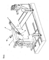
- Said Figure 1 also shows the positioning device (3) provided with means (8) for rotating the positioning arm (6) through up to 360° around the central axis (Y) of the tube (7) to be bent, so as to be able advantageously to bend said tube (7), particularly of hybrid type, in various bending planes having in common said central axis (Y), having among other things the possibility of locking the tube in the intermediate area and being able to start indifferently from either of its ends, thus overcoming the disadvantages of the known machines.
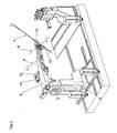
- FIG. 2 shows the machine of fig. 1 , highlighting the positioning arm (6) equipped with a locking device (9) for the tube (7) to be bent.
- Said locking device (9) is provided with means (10) for rotating through up to 360° around a fulcrum (F) so as to rotate said tube (7) for the purpose of being able to bend either end of said tube (7) alternatively by means of device (4) on the basis of a preset work programme.
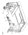
- Figure 3 shows the machine of figure 1 , demonstrating another embodiment according to which the positioning arm (6), equipped with two locking devices (12) and (13) for the tube (7) to be bent, is provided with means (10) and (11) for rotating through up to 360° around fulcrum (F) and fulcrum (G) so as to rotate said tube (7) for the purpose of being able to bend either end of said tube (7) alternatively and/or an intermediate part of said tube by means of device (4) on the basis of a preset work programme.
- Figure 4 shows the machine of fig. 1 , equipped with a further bending device (14) capable of moving and being moved by known movement means. Equipping machine 1 with further possibilities of bending enables a considerable increase in the possibilities of bending said tube (7).
- the machine 1 can be susceptible of numerous variations particularly as regards the positioning of the elements without thereby departing from the scope of the invention as defined by the appended claims.
Abstract
Description
- The present invention relates to a machine for bending tubes of any length (short, medium or long) according to the preamble of claim 1 (see
US-B1-6 434 995 ), without having to withdraw the tube to be bent, in order to effect curves with a different radius and/or in different bending planes. - The machine which is the subject of the present invention is also suitable for bending tubes designated as hybrid, that is to say tubes formed from lengths of metal and lengths of rubber or other non-metallic material.
- Tube-bending machines are known which bend tubes by setting about the bending starting from one end of the tube to be bent and keeping the other end of said tube in the positioning device. Tubes bent with said known machines have the disadvantage of oscillating and/or undergoing deformation subsequently to bending because they are left lacking adequate support, in a so-called overhanging position, that is to say restrained at a single point and subjected to the force of gravity.
- In relation to the bending of tubes generally designated hybrid, that is to say tubes formed from lengths of metal and lengths of rubber or other non-metallic material, the known tube-bending machines have great difficulty in bending said hybrid tubes, because said machines set about bending the tube starting from just one end of said tube, and the bending devices can easily touch the non-metallic parts of the tube, with the risk of damaging it.
- Among tube-bending machines, an orbital machine for bending long tubes is also known, described in document
US 7.093.475 . Said machine includes a bending head mounted on a U-shaped arm which rotates around the horizontal axis of the tube to be bent. The machine described in said document has the disadvantage of being able to manipulate tubes of small size because the weight of the head mounted on the above-mentioned U-shaped arm must be small for structural reasons relating to the shape of said arm. Furthermore, the length of the tubes to be bent is anyway limited by the breadth of the U which constitutes the above-mentioned arm, the overall dimensions of the bent tube being limited by the breadth of the U formed by the above-mentioned arm. - The machine described in document
US 7.093.475 is capable of bending tubes only in one plane of curvature, having therefore a limited productive capacity. - An object of the present invention is to create a machine for bending metal or hybrid tubes, that is to say tubes formed from lengths of metal and lengths of rubber or other non-metallic material, of any size and length, with characteristics which are such as to be able to overcome the disadvantages mentioned with reference to the known art.
- These and other objects are achieved by means of a tube-bending machine according to claim 1.
- This and other preferred characteristics will become clearer from the following description of some embodiments illustrated, purely by way of example in the attached drawings in which:
-
Figure 1 shows a perspective view of the whole of a tube-bending machine which is the subject of the present invention with a positioning device suitable for rotating through up to 360°; -
Figure 2 shows the machine offig. 1 highlighting the locking device and the means suitable for rotating said device up to 360° around fulcrum (F); -
Figure 3 shows the machine offig. 1 highlighting the two locking devices and the means suitable for rotating said devices up to 360° around fulcrums (F) and (G); -
Figure 4 shows the machine of fig. i with a second bending device. - With reference to
Figure 1 , no. (1) indicates a machine for bending tubes, consisting of a supporting base (2) which supports a positioning device (3) for the tube to be bent (7) of wholly metallic or hybrid type, that is to say formed from lengths of metal and lengths of rubber or other non-metallic material, by one or more devices (4) for bending the tube (7) to be bent. Said positioning device (3) consists of a turret (5) and a positioning arm (6). - Said machine also includes means known to persons skilled in the art for the purpose of making the positioning device (3), by means of the translation of turret (5) and/or device (4), take up mutual positions for the purpose of allowing said device (4) to be moved, according to methods known to persons skilled in the art, for the purpose of bending said tube (7) on the basis of the preset work programme.
- Said
Figure 1 also shows the positioning device (3) provided with means (8) for rotating the positioning arm (6) through up to 360° around the central axis (Y) of the tube (7) to be bent, so as to be able advantageously to bend said tube (7), particularly of hybrid type, in various bending planes having in common said central axis (Y), having among other things the possibility of locking the tube in the intermediate area and being able to start indifferently from either of its ends, thus overcoming the disadvantages of the known machines. -
Figure 2 shows the machine offig. 1 , highlighting the positioning arm (6) equipped with a locking device (9) for the tube (7) to be bent. Said locking device (9) is provided with means (10) for rotating through up to 360° around a fulcrum (F) so as to rotate said tube (7) for the purpose of being able to bend either end of said tube (7) alternatively by means of device (4) on the basis of a preset work programme. -
Figure 3 shows the machine offigure 1 , demonstrating another embodiment according to which the positioning arm (6), equipped with two locking devices (12) and (13) for the tube (7) to be bent, is provided with means (10) and (11) for rotating through up to 360° around fulcrum (F) and fulcrum (G) so as to rotate said tube (7) for the purpose of being able to bend either end of said tube (7) alternatively and/or an intermediate part of said tube by means of device (4) on the basis of a preset work programme. -
Figure 4 shows the machine offig. 1 , equipped with a further bending device (14) capable of moving and being moved by known movement means. Equipping machine 1 with further possibilities of bending enables a considerable increase in the possibilities of bending said tube (7). - The machine 1 can be susceptible of numerous variations particularly as regards the positioning of the elements without thereby departing from the scope of the invention as defined by the appended claims.
Claims (3)
- A tube-bending machine (1), comprising:- a supporting base (2);- a positioning device (3) for the tube (7) to be bent,- at least one device (4) for bending the tube (7) to be bent,- means for making the positioning device (3) and the device (4) for bending said tube (7) take up mutual positions for bending said tube (7), said positioning device (3) comprising a turret (5) and a positioning arm (6) equipped with means (8) suitable for rotating said positioning arm (6) through 360° around the central axis (Y) of the tube (7) to be bent, in order to position said tube (7) for the purpose of being bent by means of said device (4) in various bending planes characterised in that said positioning arm (6) is equipped with at least one locking device (9) for the tube (7) to be bent equipped with means (10) suitable for rotating said locking device (9) through up to 360° around a fulcrum (F) in order to rotate said tube (7) for the purpose of bending either end of the tube (7) alternatively by means of device (4);
- A tube-bending machine (1) according to claim 1 characterised in that said positioning arm (6) is equipped with two locking devices (12) and (13) for the tube (7) to be bent and means (10) and (11) suitable for rotating said devices through up to 360° respectively around a fulcrum (F) and a fulcrum (G) in order to rotate said tube (7) for the purpose of bending either end of tube (7) alternatively by means of device (4);
- A tube-bending machine (1) according to one of the preceding claims characterised in that it comprises at least one second bending device (14).
Applications Claiming Priority (1)
| Application Number | Priority Date | Filing Date | Title |
|---|---|---|---|
| IT001355A ITMI20071355A1 (en) | 2007-07-09 | 2007-07-09 | BENDER MACHINE |
Publications (2)
| Publication Number | Publication Date |
|---|---|
| EP2014382A1 EP2014382A1 (en) | 2009-01-14 |
| EP2014382B1 true EP2014382B1 (en) | 2010-10-27 |
Family
ID=39929889
Family Applications (1)
| Application Number | Title | Priority Date | Filing Date |
|---|---|---|---|
| EP08011762A Not-in-force EP2014382B1 (en) | 2007-07-09 | 2008-06-30 | Tube bending machine |
Country Status (5)
| Country | Link |
|---|---|
| US (1) | US20090173127A1 (en) |
| EP (1) | EP2014382B1 (en) |
| AT (1) | ATE485900T1 (en) |
| DE (1) | DE602008003160D1 (en) |
| IT (1) | ITMI20071355A1 (en) |
Families Citing this family (6)
| Publication number | Priority date | Publication date | Assignee | Title |
|---|---|---|---|---|
| WO2014185531A1 (en) * | 2013-05-17 | 2014-11-20 | 株式会社オプトン | Bending processing system |
| JP6619560B2 (en) * | 2015-04-15 | 2019-12-11 | 株式会社オプトン | Bending machine |
| US11007563B2 (en) * | 2016-04-27 | 2021-05-18 | Advanced Orthodontic Solutions | Wire bending machine |
| DE102018128903A1 (en) * | 2018-11-16 | 2020-05-20 | Wafios Aktiengesellschaft | Device for bending rod-shaped workpieces |
| CN109549699B (en) * | 2018-12-04 | 2021-05-25 | 中南大学湘雅医院 | Automatic moulding mechanism of medical interior fixed plate of pitch arc type titanium alloy |
| CN109530509B (en) * | 2018-12-04 | 2020-01-31 | 中国科学院宁波材料技术与工程研究所 | Automatic moulding mechanism of medical interior fixed plate of sharp type titanium alloy |
Family Cites Families (6)
| Publication number | Priority date | Publication date | Assignee | Title |
|---|---|---|---|---|
| US6434995B1 (en) * | 1999-10-15 | 2002-08-20 | Usui Kokusai Sangyo Kaisha Limited | Method of bending small diameter metal pipe and its apparatus |
| JP4319314B2 (en) * | 2000-01-31 | 2009-08-26 | 株式会社オプトン | Bending machine |
| FR2859653B1 (en) | 2003-09-12 | 2006-03-17 | Silfax Sa | ORBITAL MACHINE FOR BENDING TUBES |
| JP4591908B2 (en) * | 2003-12-15 | 2010-12-01 | 臼井国際産業株式会社 | Pipe bending machine |
| JP5090636B2 (en) * | 2004-09-27 | 2012-12-05 | 株式会社オプトン | Bending machine |
| DE102004048036A1 (en) * | 2004-09-28 | 2006-04-06 | Ras Reinhardt Maschinenbau Gmbh | bender |
-
2007
- 2007-07-09 IT IT001355A patent/ITMI20071355A1/en unknown
-
2008
- 2008-06-30 EP EP08011762A patent/EP2014382B1/en not_active Not-in-force
- 2008-06-30 AT AT08011762T patent/ATE485900T1/en not_active IP Right Cessation
- 2008-06-30 DE DE602008003160T patent/DE602008003160D1/en active Active
- 2008-07-07 US US12/168,574 patent/US20090173127A1/en not_active Abandoned
Also Published As
| Publication number | Publication date |
|---|---|
| ATE485900T1 (en) | 2010-11-15 |
| EP2014382A1 (en) | 2009-01-14 |
| DE602008003160D1 (en) | 2010-12-09 |
| ITMI20071355A1 (en) | 2009-01-10 |
| US20090173127A1 (en) | 2009-07-09 |
Similar Documents
| Publication | Publication Date | Title |
|---|---|---|
| EP2014382B1 (en) | Tube bending machine | |
| CN103507071A (en) | Robot system and method for manufacturing assembly fittings | |
| RU2628591C2 (en) | Device and method for edging using rollers | |
| JP6101454B2 (en) | Work processing apparatus and method of moving a mold in the work processing apparatus | |
| JP2014065079A (en) | Panel bending machine with universal bearing blade | |
| JP2010052002A (en) | Bending apparatus and bending method | |
| US20150040634A1 (en) | Bending machine having a bending head that is movable about a stationary bending shank | |
| JP5389522B2 (en) | Coil forming method and coil forming apparatus | |
| JP2010222138A (en) | Outrigger device | |
| JP2801170B2 (en) | Bending equipment for long objects | |
| JP6154229B2 (en) | Segment gripping device for shield machine | |
| JPH06198348A (en) | Roll bending method | |
| JP2014117726A (en) | Hemming apparatus | |
| EP1494825B1 (en) | Method and machine for bending of wire rods, wires, tubes or other material of prismatic cross section | |
| JP2008234891A (en) | Supporting unit of compression head | |
| KR102583197B1 (en) | Glass tube dual-directional stretching method, tools, and fine-tuning system | |
| US8220304B2 (en) | Machine for cambering, forming, folding or bending bars, wires or extruded shapes | |
| JP5505823B2 (en) | Bending device and bending method | |
| JP2014097565A (en) | Gripper of robot for assembling vehicle | |
| CN205436866U (en) | A frock for machine people that bends | |
| WO2015166875A1 (en) | Tire support mechanism and tire changer | |
| KR101117162B1 (en) | Bending device | |
| JP2811281B2 (en) | Bending equipment for small diameter metal pipes | |
| CN216679678U (en) | Plate bending machine with positioning device | |
| JPH06142775A (en) | Roll bender |
Legal Events
| Date | Code | Title | Description |
|---|---|---|---|
| PUAI | Public reference made under article 153(3) epc to a published international application that has entered the european phase |
Free format text: ORIGINAL CODE: 0009012 |
|
| 17P | Request for examination filed |
Effective date: 20080702 |
|
| AK | Designated contracting states |
Kind code of ref document: A1 Designated state(s): AT BE BG CH CY CZ DE DK EE ES FI FR GB GR HR HU IE IS IT LI LT LU LV MC MT NL NO PL PT RO SE SI SK TR |
|
| AX | Request for extension of the european patent |
Extension state: AL BA MK RS |
|
| AKX | Designation fees paid |
Designated state(s): AT BE BG CH CY CZ DE DK EE ES FI FR GB GR HR HU IE IS IT LI LT LU LV MC MT NL NO PL PT RO SE SI SK TR |
|
| GRAP | Despatch of communication of intention to grant a patent |
Free format text: ORIGINAL CODE: EPIDOSNIGR1 |
|
| GRAS | Grant fee paid |
Free format text: ORIGINAL CODE: EPIDOSNIGR3 |
|
| GRAA | (expected) grant |
Free format text: ORIGINAL CODE: 0009210 |
|
| AK | Designated contracting states |
Kind code of ref document: B1 Designated state(s): AT BE BG CH CY CZ DE DK EE ES FI FR GB GR HR HU IE IS IT LI LT LU LV MC MT NL NO PL PT RO SE SI SK TR |
|
| REG | Reference to a national code |
Ref country code: GB Ref legal event code: FG4D |
|
| REG | Reference to a national code |
Ref country code: CH Ref legal event code: EP |
|
| REG | Reference to a national code |
Ref country code: IE Ref legal event code: FG4D |
|
| REF | Corresponds to: |
Ref document number: 602008003160 Country of ref document: DE Date of ref document: 20101209 Kind code of ref document: P |
|
| REG | Reference to a national code |
Ref country code: NL Ref legal event code: VDEP Effective date: 20101027 |
|
| LTIE | Lt: invalidation of european patent or patent extension |
Effective date: 20101027 |
|
| PG25 | Lapsed in a contracting state [announced via postgrant information from national office to epo] |
Ref country code: NO Free format text: LAPSE BECAUSE OF FAILURE TO SUBMIT A TRANSLATION OF THE DESCRIPTION OR TO PAY THE FEE WITHIN THE PRESCRIBED TIME-LIMIT Effective date: 20110127 Ref country code: LT Free format text: LAPSE BECAUSE OF FAILURE TO SUBMIT A TRANSLATION OF THE DESCRIPTION OR TO PAY THE FEE WITHIN THE PRESCRIBED TIME-LIMIT Effective date: 20101027 |
|
| PG25 | Lapsed in a contracting state [announced via postgrant information from national office to epo] |
Ref country code: SE Free format text: LAPSE BECAUSE OF FAILURE TO SUBMIT A TRANSLATION OF THE DESCRIPTION OR TO PAY THE FEE WITHIN THE PRESCRIBED TIME-LIMIT Effective date: 20101027 Ref country code: HR Free format text: LAPSE BECAUSE OF FAILURE TO SUBMIT A TRANSLATION OF THE DESCRIPTION OR TO PAY THE FEE WITHIN THE PRESCRIBED TIME-LIMIT Effective date: 20101027 Ref country code: BG Free format text: LAPSE BECAUSE OF FAILURE TO SUBMIT A TRANSLATION OF THE DESCRIPTION OR TO PAY THE FEE WITHIN THE PRESCRIBED TIME-LIMIT Effective date: 20110127 Ref country code: LV Free format text: LAPSE BECAUSE OF FAILURE TO SUBMIT A TRANSLATION OF THE DESCRIPTION OR TO PAY THE FEE WITHIN THE PRESCRIBED TIME-LIMIT Effective date: 20101027 Ref country code: AT Free format text: LAPSE BECAUSE OF FAILURE TO SUBMIT A TRANSLATION OF THE DESCRIPTION OR TO PAY THE FEE WITHIN THE PRESCRIBED TIME-LIMIT Effective date: 20101027 Ref country code: FI Free format text: LAPSE BECAUSE OF FAILURE TO SUBMIT A TRANSLATION OF THE DESCRIPTION OR TO PAY THE FEE WITHIN THE PRESCRIBED TIME-LIMIT Effective date: 20101027 Ref country code: SI Free format text: LAPSE BECAUSE OF FAILURE TO SUBMIT A TRANSLATION OF THE DESCRIPTION OR TO PAY THE FEE WITHIN THE PRESCRIBED TIME-LIMIT Effective date: 20101027 Ref country code: NL Free format text: LAPSE BECAUSE OF FAILURE TO SUBMIT A TRANSLATION OF THE DESCRIPTION OR TO PAY THE FEE WITHIN THE PRESCRIBED TIME-LIMIT Effective date: 20101027 Ref country code: PT Free format text: LAPSE BECAUSE OF FAILURE TO SUBMIT A TRANSLATION OF THE DESCRIPTION OR TO PAY THE FEE WITHIN THE PRESCRIBED TIME-LIMIT Effective date: 20110228 Ref country code: IS Free format text: LAPSE BECAUSE OF FAILURE TO SUBMIT A TRANSLATION OF THE DESCRIPTION OR TO PAY THE FEE WITHIN THE PRESCRIBED TIME-LIMIT Effective date: 20110227 |
|
| PG25 | Lapsed in a contracting state [announced via postgrant information from national office to epo] |
Ref country code: GR Free format text: LAPSE BECAUSE OF FAILURE TO SUBMIT A TRANSLATION OF THE DESCRIPTION OR TO PAY THE FEE WITHIN THE PRESCRIBED TIME-LIMIT Effective date: 20110128 Ref country code: BE Free format text: LAPSE BECAUSE OF FAILURE TO SUBMIT A TRANSLATION OF THE DESCRIPTION OR TO PAY THE FEE WITHIN THE PRESCRIBED TIME-LIMIT Effective date: 20101027 |
|
| PG25 | Lapsed in a contracting state [announced via postgrant information from national office to epo] |
Ref country code: CZ Free format text: LAPSE BECAUSE OF FAILURE TO SUBMIT A TRANSLATION OF THE DESCRIPTION OR TO PAY THE FEE WITHIN THE PRESCRIBED TIME-LIMIT Effective date: 20101027 Ref country code: ES Free format text: LAPSE BECAUSE OF FAILURE TO SUBMIT A TRANSLATION OF THE DESCRIPTION OR TO PAY THE FEE WITHIN THE PRESCRIBED TIME-LIMIT Effective date: 20110207 Ref country code: EE Free format text: LAPSE BECAUSE OF FAILURE TO SUBMIT A TRANSLATION OF THE DESCRIPTION OR TO PAY THE FEE WITHIN THE PRESCRIBED TIME-LIMIT Effective date: 20101027 |
|
| PG25 | Lapsed in a contracting state [announced via postgrant information from national office to epo] |
Ref country code: RO Free format text: LAPSE BECAUSE OF FAILURE TO SUBMIT A TRANSLATION OF THE DESCRIPTION OR TO PAY THE FEE WITHIN THE PRESCRIBED TIME-LIMIT Effective date: 20101027 Ref country code: SK Free format text: LAPSE BECAUSE OF FAILURE TO SUBMIT A TRANSLATION OF THE DESCRIPTION OR TO PAY THE FEE WITHIN THE PRESCRIBED TIME-LIMIT Effective date: 20101027 Ref country code: PL Free format text: LAPSE BECAUSE OF FAILURE TO SUBMIT A TRANSLATION OF THE DESCRIPTION OR TO PAY THE FEE WITHIN THE PRESCRIBED TIME-LIMIT Effective date: 20101027 Ref country code: DK Free format text: LAPSE BECAUSE OF FAILURE TO SUBMIT A TRANSLATION OF THE DESCRIPTION OR TO PAY THE FEE WITHIN THE PRESCRIBED TIME-LIMIT Effective date: 20101027 |
|
| PLBE | No opposition filed within time limit |
Free format text: ORIGINAL CODE: 0009261 |
|
| STAA | Information on the status of an ep patent application or granted ep patent |
Free format text: STATUS: NO OPPOSITION FILED WITHIN TIME LIMIT |
|
| 26N | No opposition filed |
Effective date: 20110728 |
|
| REG | Reference to a national code |
Ref country code: DE Ref legal event code: R097 Ref document number: 602008003160 Country of ref document: DE Effective date: 20110728 |
|
| PG25 | Lapsed in a contracting state [announced via postgrant information from national office to epo] |
Ref country code: IT Free format text: LAPSE BECAUSE OF FAILURE TO SUBMIT A TRANSLATION OF THE DESCRIPTION OR TO PAY THE FEE WITHIN THE PRESCRIBED TIME-LIMIT Effective date: 20101027 Ref country code: MT Free format text: LAPSE BECAUSE OF FAILURE TO SUBMIT A TRANSLATION OF THE DESCRIPTION OR TO PAY THE FEE WITHIN THE PRESCRIBED TIME-LIMIT Effective date: 20101027 |
|
| REG | Reference to a national code |
Ref country code: FR Ref legal event code: ST Effective date: 20120229 |
|
| REG | Reference to a national code |
Ref country code: IE Ref legal event code: MM4A |
|
| PG25 | Lapsed in a contracting state [announced via postgrant information from national office to epo] |
Ref country code: IE Free format text: LAPSE BECAUSE OF NON-PAYMENT OF DUE FEES Effective date: 20110630 Ref country code: FR Free format text: LAPSE BECAUSE OF NON-PAYMENT OF DUE FEES Effective date: 20110630 |
|
| REG | Reference to a national code |
Ref country code: CH Ref legal event code: PL |
|
| REG | Reference to a national code |
Ref country code: CH Ref legal event code: PL |
|
| GBPC | Gb: european patent ceased through non-payment of renewal fee |
Effective date: 20120630 |
|
| PG25 | Lapsed in a contracting state [announced via postgrant information from national office to epo] |
Ref country code: MC Free format text: LAPSE BECAUSE OF NON-PAYMENT OF DUE FEES Effective date: 20110630 Ref country code: CH Free format text: LAPSE BECAUSE OF NON-PAYMENT OF DUE FEES Effective date: 20120630 Ref country code: GB Free format text: LAPSE BECAUSE OF NON-PAYMENT OF DUE FEES Effective date: 20120630 Ref country code: LI Free format text: LAPSE BECAUSE OF NON-PAYMENT OF DUE FEES Effective date: 20120630 |
|
| PG25 | Lapsed in a contracting state [announced via postgrant information from national office to epo] |
Ref country code: LU Free format text: LAPSE BECAUSE OF NON-PAYMENT OF DUE FEES Effective date: 20110630 Ref country code: CY Free format text: LAPSE BECAUSE OF FAILURE TO SUBMIT A TRANSLATION OF THE DESCRIPTION OR TO PAY THE FEE WITHIN THE PRESCRIBED TIME-LIMIT Effective date: 20101027 |
|
| PG25 | Lapsed in a contracting state [announced via postgrant information from national office to epo] |
Ref country code: TR Free format text: LAPSE BECAUSE OF FAILURE TO SUBMIT A TRANSLATION OF THE DESCRIPTION OR TO PAY THE FEE WITHIN THE PRESCRIBED TIME-LIMIT Effective date: 20101027 |
|
| PG25 | Lapsed in a contracting state [announced via postgrant information from national office to epo] |
Ref country code: HU Free format text: LAPSE BECAUSE OF FAILURE TO SUBMIT A TRANSLATION OF THE DESCRIPTION OR TO PAY THE FEE WITHIN THE PRESCRIBED TIME-LIMIT Effective date: 20101027 |
|
| PGFP | Annual fee paid to national office [announced via postgrant information from national office to epo] |
Ref country code: DE Payment date: 20190627 Year of fee payment: 12 |
|
| REG | Reference to a national code |
Ref country code: DE Ref legal event code: R119 Ref document number: 602008003160 Country of ref document: DE |
|
| PG25 | Lapsed in a contracting state [announced via postgrant information from national office to epo] |
Ref country code: DE Free format text: LAPSE BECAUSE OF NON-PAYMENT OF DUE FEES Effective date: 20210101 |