EP1976449B1 - System to manufacture custom orthodontic appliances - Google Patents
System to manufacture custom orthodontic appliances Download PDFInfo
- Publication number
- EP1976449B1 EP1976449B1 EP07704201.8A EP07704201A EP1976449B1 EP 1976449 B1 EP1976449 B1 EP 1976449B1 EP 07704201 A EP07704201 A EP 07704201A EP 1976449 B1 EP1976449 B1 EP 1976449B1
- Authority
- EP
- European Patent Office
- Prior art keywords
- bracket
- slot
- electrical discharge
- bracket slot
- electrode
- Prior art date
- Legal status (The legal status is an assumption and is not a legal conclusion. Google has not performed a legal analysis and makes no representation as to the accuracy of the status listed.)
- Active
Links
Images


Classifications
-
- A—HUMAN NECESSITIES
- A61—MEDICAL OR VETERINARY SCIENCE; HYGIENE
- A61C—DENTISTRY; APPARATUS OR METHODS FOR ORAL OR DENTAL HYGIENE
- A61C7/00—Orthodontics, i.e. obtaining or maintaining the desired position of teeth, e.g. by straightening, evening, regulating, separating, or by correcting malocclusions
- A61C7/12—Brackets; Arch wires; Combinations thereof; Accessories therefor
- A61C7/14—Brackets; Fixing brackets to teeth
- A61C7/145—Lingual brackets
-
- B—PERFORMING OPERATIONS; TRANSPORTING
- B23—MACHINE TOOLS; METAL-WORKING NOT OTHERWISE PROVIDED FOR
- B23H—WORKING OF METAL BY THE ACTION OF A HIGH CONCENTRATION OF ELECTRIC CURRENT ON A WORKPIECE USING AN ELECTRODE WHICH TAKES THE PLACE OF A TOOL; SUCH WORKING COMBINED WITH OTHER FORMS OF WORKING OF METAL
- B23H1/00—Electrical discharge machining, i.e. removing metal with a series of rapidly recurring electrical discharges between an electrode and a workpiece in the presence of a fluid dielectric
-
- B—PERFORMING OPERATIONS; TRANSPORTING
- B23—MACHINE TOOLS; METAL-WORKING NOT OTHERWISE PROVIDED FOR
- B23H—WORKING OF METAL BY THE ACTION OF A HIGH CONCENTRATION OF ELECTRIC CURRENT ON A WORKPIECE USING AN ELECTRODE WHICH TAKES THE PLACE OF A TOOL; SUCH WORKING COMBINED WITH OTHER FORMS OF WORKING OF METAL
- B23H9/00—Machining specially adapted for treating particular metal objects or for obtaining special effects or results on metal objects
-
- B—PERFORMING OPERATIONS; TRANSPORTING
- B33—ADDITIVE MANUFACTURING TECHNOLOGY
- B33Y—ADDITIVE MANUFACTURING, i.e. MANUFACTURING OF THREE-DIMENSIONAL [3-D] OBJECTS BY ADDITIVE DEPOSITION, ADDITIVE AGGLOMERATION OR ADDITIVE LAYERING, e.g. BY 3-D PRINTING, STEREOLITHOGRAPHY OR SELECTIVE LASER SINTERING
- B33Y80/00—Products made by additive manufacturing
-
- Y—GENERAL TAGGING OF NEW TECHNOLOGICAL DEVELOPMENTS; GENERAL TAGGING OF CROSS-SECTIONAL TECHNOLOGIES SPANNING OVER SEVERAL SECTIONS OF THE IPC; TECHNICAL SUBJECTS COVERED BY FORMER USPC CROSS-REFERENCE ART COLLECTIONS [XRACs] AND DIGESTS
- Y10—TECHNICAL SUBJECTS COVERED BY FORMER USPC
- Y10T—TECHNICAL SUBJECTS COVERED BY FORMER US CLASSIFICATION
- Y10T29/00—Metal working
- Y10T29/49—Method of mechanical manufacture
- Y10T29/49567—Dental appliance making
- Y10T29/49568—Orthodontic device making
Description
- The present invention relates generally to the field of orthodontics, particularly to the manufacture of orthodontic appliances. The present invention also relates to a system, program product, and related methods for designing and manufacturing orthodontic appliances for the purpose of straightening the teeth of a patient and custom precision brackets made in accordance with the methods.
- Orthodontic treatment applied to straighten or align teeth of a patient dates back hundreds of years. The treatment generally included use of wires wrapped around the patient's teeth. At around the mid-1970s, chiefly due to improvements in adhesive technology, the preferred method shifted to bonding brackets directly onto the teeth and running elastic wires of rectangular cross-sectional shape through slots in the bracket. Typically, the brackets are off-the-shelf products. In most cases, they are adapted to a certain tooth, for instance an upper canine, but not to the individual tooth of a specific patient. The adaptation of the bracket to the individual tooth is generally performed by filling the gap between tooth surface and bracket surface with adhesive to thereby bond the bracket to the tooth such that the bracket slot, when the teeth are moved to a finish position, lies in flat horizontal plane. The driving force for moving the teeth to the desired finish position is provided by the archwire. For lingual brackets, a system has been developed by Thomas Creekmore, for example, that has vertical bracket slots. This allows an easier insertion of the wire. The longer side of the wire is therefore oriented vertically.
- The wires used in orthodontic treatment today are also generally off-the-shelf products. If they need to be individualized by the orthodontist, the goal is to do so with as few modifications as possible. According to such method, the brackets are designed in a manner so that at the end of treatment, when teeth are aligned, the bracket slots are supposed to be located and oriented in a planar manner. This means that a wire that would run passively through the slots, without applying any force, would be planar (flat). This treatment regimen is known as "straight wire." The further the archwire is away from the tooth surface, the more difficult it is to achieve a precise finishing position for each tooth. An error of only 10 degrees, for example, in torque (rotation around the wire axis) may well induce a vertical error in tooth position of more than 1 mm. Thus, recognized by Applicant is the need for a precision brackets slot positioned as close to the tooth surfaces as possible which, in conjunction with a customized archwire, can form a precision archwire-bracket slot interface to thereby minimize torque error.
- Another problem in orthodontics is to determine the correct bracket position. At the time of bonding, teeth may be oriented far away from the desired position. So the task to locate the brackets in a manner that a flat planar archwire drives teeth to the correct position requires a lot of experience and visual imagination. The result is that at the end of treatment a lot of time is lost to perform necessary adjustments to either bracket position or wire shape. This problem can be solved by creating an ideal setup, either virtually using three-dimensional scan data of the dentition or physically by separating a dental model of the dentition into single teeth and setting up the teeth in a wax bed in an ideal position. For example,
U.S. Patent No. 6,648,640 by Rubbert et al. , titled "Interactive Orthodontic Care System Based On Intra-Oral Scanning of Teeth," describes a wire-based approach to orthodontics based on generic brackets and a customized orthodontic archwire. The archwire can have complex twists and bends, and as such is not necessarily a flat planar wire. This patent document also describes a scanning system for creating three-dimensional virtual models of a dentition and an interactive, computerized treatment planning system based on the models of the scanned dentition. As part of the treatment planning, virtual brackets are placed on virtual teeth and the teeth moved to a desired position by a human operator exercising clinical judgment. The three-dimensional virtual model of the dentition plus brackets in a malocclused condition is exported to a rapid prototyping device for manufacture of a physical model of the dentition plus brackets. -
US 5,736,015 describes an electrical discharge machining apparatus for machining dental prostheses, which are secured in a work holder and covered by an electrolytic liquid. -
EP 0290247 relates to the production of orthodontic brackets by using ultrasonic machining. It is described that tools used in ultrasonic machining can be made inter alia by electric discharge machining. -
U.S. Patent No. 6,776,614 by Wiechmann et al. , titled "Modular System for Customized Orthodontic Appliances," describes a wire-based approach to orthodontics based on customized orthodontic brackets and a customized orthodontic archwire. This patent document further describes designing the brackets on a computer as a combination of three-dimensional virtual objects including a virtual bracket bonding pad and a virtual bracket body retrieved from a library of virtual bracket bodies. The virtual brackets can be represented as a file containing digital shape data and can be exported to a rapid prototype fabrication device. - Recent developments in orthodontics include the use of rapid prototyping technology to form the brackets. Rapid prototyping machines can be used for models of the brackets which are then used to form molds to form the brackets. These molds generally have a cavity defining the bracket and can have a channel forming a pathway to pour bracket-forming material into the mold. Solidified bracket-forming material remaining in the channel forms a runner which must be removed. Also, if the bracket slot is not formed as part of the molding process, a bracket slot must be cut into the bracket body.
- Various methods of forming the bracket slot can include casting, grinding or milling. For example,
WO94/10935 by Andreiko et al. - Such processes are deficient in describing systems, apparatus, or methods for creating a highly-precise bracket slot, creating an undercut in the sidewalls of the bracket slots, cutting an investment cast bracket off a runner, or cutting a highly precise tub into the bracket body. Although the desire for precision brackets has been noted in Wiechmann, D., "A New Bracket System for Lingual Orthodontic Treatment, Part 2: First Clinical Experiences and Further Development," J. Orofac. Orthop. (2003), there has to-date not been recognition, of the need for a system, apparatus, program product, and methods of forming enhanced precision bracket slots or tubes having such desirable features that can be obtained using electrical discharge machining technology, e.g. planar machined surfaces of low tolerances allowing precise fit of an adjacent archwire.
-
EP 1 350 482 discloses an orthodontic bracket having increased adhesive strength to a tooth surface by way of having undercuts formed by plastic deformation, and a manufacturing method thereof. - In view of the foregoing, it is an object of the present invention to overcome deficiencies of known brackets and known production methods.
- The present invention achieves the above mentioned objects by providing a system, program product, and method of manufacturing orthodontic appliances which can provide enhanced precision in forming a precision customized bracket slot in each bracket body of the orthodontic appliance. For example, according to embodiments of the present invention, bracket slot configurations can be formed that were not previously able to be formed. Further, according to embodiments of the present invention, a custom archwire and each of the precision custom bracket slots can form a high-precision archwire-bracket slot interface which can significantly reduce or minimize torque error. An archwire is a generally U-shaped or arcuately shaped wire having a form and dimensions generally corresponding to the inner surface of the arrangement of teeth in the oral cavity. It has been found by the present inventors that use of electrical discharge machining in conjunction with virtual bracket design, if employed to form the bracket slot in the bracket body, can provide enhanced precision and can allow for runner removal. Still further, according to an embodiment of the present invention, electrical discharge machining in conjunction with virtual bracket design can provide enhanced precision and can allow for a manufacturing process including effective runner removal. Preferably, runner removal is effected simultaneously to machining the bracket slot, e.g. the process of machining the slot is effectively coupled with runner removal. This is realized in embodiments of the invention, in which the runner or a fixture section, respectively, is attached to the section of the bracket body that is arranged in the plane or attached to the plane of the open surface of the bracket slot to be machined. Accordingly, machining of the bracket slot in combination with removal of material filling the bracket slot results in concurrent removal of the runner or fixture section attached thereto.
- More specifically, in an embodiment of the present invention, a system to manufacture orthodontic appliances can include a virtual orthodontic appliance design computer having a processor, memory coupled to the processor, and orthodontic appliance design program product stored in the memory. The orthodontic appliance design program product can include instructions to perform the operation of receiving patient dentition data typically obtained through various methods known to those skilled in the art and can include those to perform the operation of designing a virtual dimensional representation of the orthodontic appliance defining virtual orthodontic appliance design data in response to the received patient dentition data. The orthodontic appliance can include an archwire which, for example, can be customized, and a plurality of precision customized brackets each including a bracket body having a tooth facing bonding surface, a bracket pad connected to the bracket body, and a bracket slot. Accordingly, a bracket comprises a bracket body having a bracket slot and a bracket pad having a tooth bonding surface. In a preferred embodiment, a bracket is a single-piece element comprising a bracket body, a bracket slot, and a bracket pad.
- The system can also include a mold forming apparatus which can utilize various techniques, such as, for example, rapid prototyping to create a mold used to thereby form the custom brackets. According to an embodiment of the present invention, the mold can be configured to simultaneously form both the bracket body and bracket pad and is positioned to receive a bracket-forming material. The mold forming apparatus also includes a device positioned to dispense the bracket-forming material into the mold. Each mold generally has a cavity for each of the brackets and for defining peripheries of the bracket when the bracket-forming material is positioned therein, and a channel for defining peripheries of a runner when filled with the bracket-forming material. Each molded bracket body can be connected to the runner when removed from the mold. Preferably, the runner comprises a fixture section that can be positioned into a receiving section of the system for orienting the bracket for machining by the electrical discharge machining apparatus. In this way, the fixture section can be used for orienting the bracket for machining independent from patient dentition data comprising e.g. the shape of the tooth bonding surface or, preferably, in accordance with patient dentition data, e.g. defining the tooth bonding surface and/or an inclination of the bracket slot towards the tooth bonding surface.
- In the alternative to molding a bracket body having a runner that comprises a fixture section, a bracket body can comprise a fixture section independent from the runner. Further, the bracket body can be produced by another production process, e.g. by generating its three-dimensional shape by machining or, preferably, by fusing a precursor material yielding a desired material into a pre-determined three-dimensional shape. The latter technique can for example employ laser irradiation to selectively fuse a precursor material along a pre-determined pattern in a numerically controlled manner essentially within the pre-determined shape of the bracket body. In the case of a metal alloy being the material constituting the bracket body, a precursor material can comprise particles of the metal alloy.
- The system can also include a data processing computer positioned, for example, in communication with the virtual orthodontic appliance design computer through a computer network and having memory and computer-aided manufacturing program product stored in the memory. The computer-aided manufacturing program product can include instructions to perform the operation of deriving electrical discharge device control instructions readable by a machine to perform the operation of forming the bracket slot responsive to the virtual orthodontic appliance design data.
- The system also includes an electrical discharge machining apparatus in communication with the data processing computer, for example, through the computer network or other communication medium known to those skilled in the art. The electrical discharge machining apparatus can include a controller having memory which can provide for computer numerical control. The controller can also include data communication program product stored in the memory which can include instructions to perform the operation of receiving or importing the electrical discharge device control instructions. The controller can also include control program product which can include instructions to derive a control signal carrying the electrical discharge device control instructions responsive to the received electrical discharge device control instructions.
- The electrical discharge machining apparatus can also include an electrical discharge device having an electrical discharge electrode assembly including an electrode. The electrodes of the electrical discharge device, for example, can come in two forms, a traveling wire electrical discharge electrode or traveling wire electrode and a die-sinker electrical discharge electrode. The electrical discharge device can include at least one drive section adapted to position the bracket in electrical discharge contact with the electrode to form the bracket slot and to simultaneously separate the bracket from the runner when forming the bracket slot responsive to the control signal, depending upon the type of bracket slot being formed.
- According to an embodiment of the present invention a system to fabricate or manufacture orthodontic appliances can include a numerical control data processor defining a controller having memory and control program product stored in the memory. The control program product can include instructions to perform the operation of deriving a numerical control signal carrying electrical discharge device control instructions to form a bracket slot in a bracket body of a bracket of an orthodontic appliance and to separate the bracket body from a runner connected to the bracket body. The system can also include an electrical discharge device in communication with the controller. The electrical discharge device can have an electrical discharge electrode assembly including an electrode and at least one drive section adapted to position the bracket body of the bracket in electrical discharge contact with the electrode responsive to the numerical control signal to form the bracket slot and to simultaneously separate the bracket body from the runner when forming the bracket slot.
- According to an embodiment of the present invention, a system to fabricate or manufacture orthodontic appliances can include a controller having memory, data communication program product stored in the memory including instructions to perform the operation of receiving electrical discharge device control instructions describing a virtual dimensional representation of a bracket slot in a bracket body of a bracket of an orthodontic appliance, and control program product also stored in the memory including instructions to perform the operation of deriving a control signal carrying the electrical discharge device control instructions responsive to the electrical discharge device control instructions. The system can also include an electrical discharge device in communication with the controller having an electrical discharge electrode assembly including an electrode and having at least one drive section adapted to position the bracket body of a bracket in electrical discharge contact with the electrode, responsive to the control signal, to form the bracket slot according to a predefined electrical discharge cutting pattern, for example, derived to substantially match associated dimensions of a preselected archwire. Beneficially, for example, this allows for the formation of an enhanced precision interface with the archwire.
- Further, embodiments of the present invention also include methods of manufacturing orthodontic appliances. For example, according to an embodiment of the present invention, a method of manufacturing orthodontic appliances includes performing the step of deriving a control signal carrying device control instructions from a virtual dimensional representation of a bracket slot in a bracket body of a bracket of an orthodontic appliance. For the purposes of this description, a virtual dimensional representation can refer to a set of data defining a dimensional representation, e.g. dimensions, contour and/or surface accuracy or tolerance. The device control instructions, for example, describe operations to execute an electrical discharge cutting pattern extending along a perimeter of the bracket slot and customized to substantially match associated dimensions of a preselected archwire to thereby form a precision interface with the archwire. The method can also include a step of executing the electrical discharge cutting pattern responsive to the control signal to form the bracket slot, e.g. by control of the electrical discharge apparatus and/or of a drive section thereof by numerical control instruction data serving as a control signal. If the bracket body is connected to a runner, for example, the method can also include the step of executing the electrical discharge cutting pattern including cutting the bracket body from the runner to separate the bracket body from the runner when forming the bracket slot. Where the bracket slot is an open-ended bracket slot, the slot can be formed adjacent the runner such that the bracket can be substantially simultaneously separated from the runner upon completing the forming of the bracket slot. According to an embodiment of the present invention, a transverse extension defining an undercut in the bracket slot also can be formed in the bracket body adjacent the closed-end of the bracket slot. Further, advantageously, where the bracket slot is a tube, the slot can be first cut using a first cutting pattern, and an associated runner, if attached, can be separated from the bracket body according to a second cutting pattern.
- According to an embodiment of the present invention, a method of manufacturing an orthodontic appliance can include the step of deriving control signal carrying device control instructions from data of a virtual dimensional representation of a bracket slot in a bracket body of a bracket of an orthodontic appliance describing operations to execute an electrical discharge cutting pattern extending along a perimeter of the bracket slot and customized to substantially match associated dimensions of a preselected archwire. Beneficially, the result includes the formation of an enhanced precision interface with the archwire and a bracket slot having a closed perimeter to thereby define a bracket tube. The method can also include the step of executing the electrical discharge cutting pattern, responsive to a control signal, to form the bracket tube. Accordingly, it is an advantage of the orthodontic appliance and of the method for its production according to the invention that at least one surface of the bracket slot or the bracket tube, respectively, preferably two opposed sides thereof, more preferably the two opposed sides as well as the base surface, in both the embodiments of an open-ended bracket slot and a closed-ended bracket slot are formed to accomodate the archwire in positive fit with high precision, e.g. tolerances of at maximum 30 µm, preferably at maximum 20 µm.
- According to another embodiment of the present invention, a method of manufacturing an orthodontic appliance can include the step of deriving a control signal carrying device control instructions from a virtual dimensional representation of a bracket slot in a bracket body of a bracket of an orthodontic appliance describing operations to execute an electrical discharge cutting pattern to form the bracket slot. The bracket slot, according to this embodiment, has an open surface end and a closed base end and two spaced-apart sides extending therebetween. The method can also include the step of executing the electrical discharge cutting pattern responsive to a control signal. The electrical discharge cutting pattern can extend along a perimeter of the bracket slot and can form a transverse extension extending into the bracket body from one of the spaced-apart sides at the base end of the bracket slot to thereby define a bracket slot undercut.
- A method of manufacturing an orthodontic appliance can include the steps of deriving a control signal carrying device control instructions describing operations to execute an electrical discharge cutting pattern to separate a bracket body of a bracket of an orthodontic appliance from a runner connected thereto, and executing the electrical discharge cutting pattern responsive to a control signal.
- Beneficially, embodiments of the present invention provide a manufacturing system and methods for manufacturing a highly-precise bracket slot, creating an undercut in the sidewalls of the bracket slots, cutting an investment cast bracket off a runner, and cutting a highly precise tub into the bracket body. Embodiments of the present invention provide a manufacturing system for fabricating at least one design feature of an orthodontic appliance or a part thereof including a data processing system deriving a control signal carrying machine control instructions from a virtual dimensional representation of the design feature and a manufacturing system fabricating the design feature that includes electrical discharge machining, which can provide a level of precision and efficiency not otherwise available in systems not employing electrical discharge sheeting. Embodiments of the present invention relate to a manufacturing system and methods for manufacturing features of an orthodontic appliance or parts thereof utilizing electrical discharge machining, which in an implementation of an embodiment provide for cutting a slot of a bracket with wire-cut EDM technology such as, for example, the Mitsubishi wire EDM SX 10.
- So that the manner in which the features and benefits of the invention, as well as others which will become apparent, may be understood in more detail, a more particular description of the invention briefly summarized above may be had by reference to the embodiments thereof which are illustrated in the appended drawings, which form a part of this specification. It is to be noted, however, that the drawings illustrate only various embodiments of the invention and are therefore not to be considered limiting of the invention's scope since it may include other effective embodiments as well. In the Figures:
-
FIG. 1 is a schematic block diagram of a system to manufacture orthodontic appliances according to an embodiment of the present invention; -
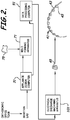
FIG. 2 is a schematic diagram of a process flow to manufacture orthodontic appliances according to an embodiment of the present invention; -
FIG. 3 is a perspective view of an orthodontic appliance according to an embodiment of the present invention; -
FIG. 4 is a perspective view of a bracket of an orthodontic appliance according to an embodiment of the present invention; -
FIG. 5 is a perspective view of a bracket of an orthodontic appliance according to an embodiment of the present invention; -
FIG. 6 is a perspective view of a bracket slot of a bracket of an orthodontic appliance according to an embodiment of the present invention; -
FIG. 7 is a perspective view of a bracket slot of a bracket of an orthodontic appliance according to an embodiment of the present invention; -
FIG. 8 is a perspective view of a mold-forming apparatus according to an embodiment of the present invention; -
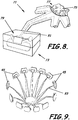
FIG. 9 is a perspective view of a mold tree according to an embodiment of the present invention; -
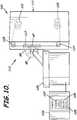
FIG. 10 is a perspective view of an electrical discharge apparatus according to an embodiment of the present invention; -
FIG. 11 is a perspective view of an electrical discharge apparatus according to an embodiment of the present invention; -
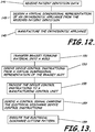
FIG. 12 is a flow diagram of a method of manufacturing an orthodontic appliance according to an embodiment of the present invention; -
FIG. 13 is a flow diagram of a method of manufacturing an orthodontic appliance according to an embodiment of the present invention; -
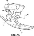
FIG. 14 is a perspective view of a bracket of an orthodontic appliance according to an embodiment of the present invention; -
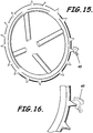
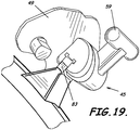
FIGS. 15-19 are perspective views of a portion of a molding apparatus and a molded bracket of an orthodontic appliance according to an embodiment of the present invention; -
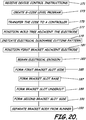
FIG. 20 is a flow diagram of a method of manufacturing an orthodontic appliance according to an embodiment of the present invention; -
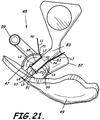
FIG. 21 is a perspective view of a bracket of an orthodontic appliance overlaid with a bracket slot cutting pattern according to an embodiment of the present invention; -
FIG. 22 is a schematic diagram of a bracket of an orthodontic appliance overlaid with a bracket slot cutting pattern according to an embodiment of the present invention; -
FIG. 23 is a sequence of numerical code in ASCII format provided to execute to an electrical discharge cutting pattern illustrated inFIG. 22 according to an embodiment of the present invention; -
FIG. 24 is block flow diagram of a method of manufacturing and orthodontic appliance according to an embodiment of the present invention; -
FIG. 25 is a perspective view of a bracket of an orthodontic appliance overlaid with a bracket slot cutting pattern according to an embodiment of the present invention; -
FIG. 26 is a schematic diagram of a bracket of an orthodontic appliance overlaid with a bracket slot cutting pattern according to an embodiment of the present invention; and -
FIG. 27 is a sequence of numerical code in ASCII format provided to execute to an electrical discharge cutting pattern illustrated inFIG. 26 according to an embodiment of the present invention. - The present invention will now be described more fully hereinafter with reference to the accompanying drawings, which illustrate embodiments of the invention. This invention may, however, be embodied in many different forms and should not be construed as limited to the illustrated embodiments set forth herein. Like numbers refer to like elements throughout. Prime notation, if used, indicates similar elements in alternative embodiments.
- As illustrated in
FIGS. 1-27 , embodiments of the present invention advantageously provide a new system, program product, and methods for fabricating features of an orthodontic appliance or parts thereof utilizing electrical discharge machining, and in an implementation of an embodiment, "cutting" or shaping various features of the appliance using traveling wire electrical discharge machining technology. The meaning of "CAD" shall include but shall not be limited to any and all technology of computer aided design. The meaning of "CAM" shall include but shall not be limited to any and all technology of computer aided manufacturing. The meaning of "CNC" or "machine control" shall include but shall not be limited to any and all technology of computer numerical control as it relates to manufacturing machinery and systems, including but not limited to rapid prototyping devices and systems. The meaning of "cut" shall include performing electrical erosion. The meaning of "EDM" or "EDM-ing" shall include but shall not be limited to any and all technology of electrical discharge machining. The term "3D" shall mean three-dimensional. The words used in this specification to describe the invention and its various embodiments are to be understood not only in the sense of their commonly defined meanings, but to include by special definition in this specification structure, material or acts beyond the scope of the commonly defined meanings. - As shown in
FIGS. 1 and2 , an embodiment of asystem 30 to fabricate or manufacture orthodontic appliances can include a virtual orthodonticappliance design computer 31 having aprocessor 33,memory 35 coupled to theprocessor 33, and orthodontic appliancedesign program product 37 stored in thememory 35. The orthodontic appliancedesign program product 37 can include instructions to perform the operation of receiving patient dentition data typically obtained through various methods known to those skilled in the art and can include those to perform the operation of designing a virtual dimensional representation of theorthodontic appliance 41 defining virtual orthodontic appliance design data in response to the received patient dentition data. - As shown in
FIGS. 4-7 , theorthodontic appliance 41 can include a customizedarchwire 43 and multiple of precision customizedbrackets 45 each including abracket body 47, abracket pad 49 connected to thebracket body 47, and abracket slot bracket body 47 having abracket slot width 55. Thebracket body 47 can also include abracket wing 57,bracket hook 59, or other design feature known to those skilled in the art. The open-end bracket slot 51 can include anopen surface end 61, aclosed base end 63, and twosides FIGS. 4 and 6 ) can also include a transverse extension or extensions adjacent thebase end 63 and extending into thebracket body 47 from one or both of thesides slot width 55. The portion of thebracket body 47 adjacent theopen surface end 61 can be arcuate or can have a more planar shape. Thesides base 63 of thebracket slot 51 can have a substantially planar surface, and, correspondingly, can be specified as having a dimensional tolerance of less than 30 microns and preferably as low as approximately eight microns, for example, along theslot width 55. The closed end (tube) bracket slot 53 (seeFIGS. 5 and 7 ) can include aclosed surface end 69 but is otherwise similar to the open-end bracket slot 51. That is, the closed-end bracket slot 53 also includes a base 63', a pair of sides 65', 66', a width 55' and can include an undercut 67'. Also similarly, thebracket tube slot 53 can be specified as having a tolerance of less than 30 microns and preferably as low as approximately eight microns along its respective slot width 55'. - As shown in
FIG. 8 , thesystem 30 can also include amold forming apparatus 71, as known to those skilled in the art, which can utilize various techniques, such as, for example, rapid prototyping to form amold 73 used to thereby form thecustom brackets 45. The various rapid prototyping techniques, for example, can include stereo lithography, laminated object manufacturing, selective laser sintering, fused deposition modeling, solid ground curing, and 3-D inkjet printing, just to name a few. According to an embodiment of the present invention, themold 73 is configured to simultaneously form both thebracket body 47 andbracket pad 49. Themold 73 is positioned to receive a bracket-formingmaterial 75 and adispensing device 77 positioned to dispense the bracket-formingmaterial 75 into themold 73. In an embodiment of the present invention, as perhaps best described inU.S. Patent No. 6,776,614 by Wiechmann et al. titled "Modular System for Customized Orthodontic Appliances," a rapid prototyping technique is used whereby a computer aided design of thebracket 45, bothbody 47 andpad 49, formed from a three-dimensional scan of impression of the teeth of a patient, is used to fabricate, e.g., wax or resin, models of thebracket 45 which are then used to form, e.g., cement,molds 73 of thebrackets 45. Eachmold 73 generally has acavity 79 for each of the ofbrackets 45 and for defining peripheries of thebracket body 47 andbracket pad 49 when the bracket-formingmaterial 75 is positioned therein and achannel 81, defining peripheries of a runner 83 (FIG. 9 ) when filled with thebracket material 75. As perhaps best shown inFIG. 14 , each moldedbracket body 47 can be connected to therunner 83 when removed from themold 73. - As shown in
FIGS. 1 and2 , thesystem 30 can also include adata processing computer 91 positioned, for example, in communication with the virtual orthodonticappliance design computer 31 through acomputer network 93 and havingmemory 95 and computer-aidedmanufacturing program product 97 stored in thememory 95. The computer-aidedmanufacturing program product 97 can include instructions to perform the operation of deriving electrical discharge device control instructions readable by a machine to perform the operation of forming thebracket slot bracket slot bracket body 47 from a fixture portion of therunner 83 when forming thebracket slot data processing computer 91. Such method can be used when a design feature, e.g.,bracket slot width 55, 55', is described by a limited number of parameters. If the design feature represents a more complex feature, then providing design input from a virtual orthodonticappliance design computer 31 would be preferable. Note, thememory 95 along with other described memory can include volatile and nonvolatile memory known to those skilled in the art including, for example, RAM, ROM, and magnetic or optical disks, just to name a few. Note also, the computer-aided manufacturing program product electrical discharge device control instructions can be in the form of microcode, programs, routines, and symbolic languages that provide a specific set or sets of ordered operations that control the functioning of the hardware and direct its operation. According to an embodiment of the present invention, the instructions are geared specifically for use by a numerical control device. - As shown in
FIGS. 1 and2 , thesystem 30 also includes an electricaldischarge machining apparatus 101 in communication with thedata processing computer 91 through, for example, thecomputer network 93, using, e.g., an RS-232-C serial communication port, or other communication medium known to those skilled in the art. The electricaldischarge machining apparatus 101 can include acontroller 103, e.g., machine control unit, havingmemory 105, which can provide for computer numerical control. Thecontroller 103 can also include a user input device or devices known to those skilled in the art and datacommunication program product 107 stored in thememory 105 which can include instructions to perform the operation of receiving or importing the electrical discharge device control instructions. Thecontroller 103 can also includecontrol program product 109, which includes instructions to derive a control signal carrying the electrical discharge device control instructions in response to the received electrical discharge device control instructions. Note, according to an embodiment of the present invention communication between, thecontroller 103 can alternatively receive (import) the electrical discharge device control instructions from thedata processing computer 91 through manual data transfer using, for example, a portable computer readable medium. - As shown in
FIGS. 10 and11 , the electricaldischarge machining apparatus 101 can also include anelectrical discharge device 111, 111', having an electricaldischarge electrode assembly electrode electrode bracket body 47 adjacent theelectrode electrical discharge device 111, 111', for example, can come in two forms, a traveling wire electrical discharge electrode or traveling wire electrode 117 (FIG. 10 ) and a die-sinker-electrical discharge electrode 119 (FIG. 11 ). - As shown in
FIG. 10 , theelectrode assembly 113 of anelectrical discharge device 111 utilizing atraveling wire electrode 117 includes a supply reel orspool 121 containing unused portions of the travelingwire electrode 117 to provide a continuous stream of supply traveling wire electrode when executing the cutting pattern and a take-up reel orspool 123 containing used portions of the traveling wire electrode to collect the traveling wire electrode supplied from thesupply reel 121 when executing the cutting pattern to form thebracket slot 51 and to provide tension to thetraveling wire electrode 117. Positioned between thesupply reel 121 and the take-upreel 123 are asupply wire guide 125 and a take-up-wire guide 127. Thewire electrode 117, constantly fed from thesupply reel 123 during cutting operations, is held between the supply and take-up guides 125, 127. The travelingwire electrode 117 typically uses water as its dielectric which can be dispensed through nozzles (not shown) positioned adjacent thebracket body 47. Electrode negative polarity can be selected to enhance manufacturing speed. Electrode positive polarity can be selected to produce a more refined bracket slot surface. A combination of the two also can be used, as desired or as necessary. - According to an embodiment of the present invention, the
electrical discharge device 111 includes an electrical discharge apparatus drive table 129, as will be understood by those skilled in the art, adapted to be moved in the X-Y plane, for example, using stepper or DC motors (not shown) in response to the control signal to position thebracket body 47 in electrical discharge contact with the travelingwire electrode 117 to thereby perform the cutting pattern to form thebracket slot wire electrode 117 to perform the cutting pattern. According to an embodiment of the present invention, thesupply guide 125 or the take-up guide 127 can further be positioned independently to thereby allow for the formation of various geometric shapes having non-parallel, non-planar surfaces. Note, the travelingwire electrode 117 via one or both of theguides bracket body 47 from therunner 83 in response to the control signal. - As shown in
FIG. 11 , theelectrode assembly 115 of an electrical discharge device 111' utilizing a die-sinkerelectrical discharge electrode 119 can include a ram (not shown) to extend the electrode adjacent the body of thebracket 45 when executing a hole formation portion of a cutting pattern to form thebracket slot 53. Note, rather than use a specific die-sinker electrode 119, a portion of the travelingwire electrode 117 disconnected from the take-upreel 125 can instead be used to function as a die-sinker electrode. Note, according to embodiments of the present invention other manufacturing methods including, for example, drilling a starter hole through thebracket body 47 or forming a starter hole through thebracket body 47 as part of the molding process, are within the scope of the present invention. Regardless of the method used to form the initial hole, once the initial hole has been formed through thebracket body 47, the end of the travelingwire electrode 117 can be connected to the take-upreel 125 to thereby function as described above in order to form abracket slot 53 in the form of a tube, described later. - As shown in
FIGS. 1-27 , embodiments of the present invention also include methods of manufacturing orthodontic appliances. For example, as shown inFIG. 12 , according to an embodiment of the present invention, a method of fabricating orthodontic appliances can include receiving patient dentition data (block 141) obtained through, for example, examination/diagnosis of a malocclusion using techniques known to those skilled in the art, designing a virtual dimensional representation of an orthodontic appliance from the received patient dentition (block 143), then manufacturing the orthodontic appliance (block 145). For example, an orthodontist or other medical professional performs an examination of a patient at the orthodontist's office to assemble data necessary to determine the patient's condition, prescribe the appropriate treatment, and specify the characteristics of the orthodontic appliance to implement the treatment. A physical model including a mandibular model and a maxillary model of the patient's lower and upper jaw, respectively, can be formed using a physical mold to be used to form a virtual model. Alternatively, a virtual model can be directly formed using various scanning techniques. Regardless of the method employed, a virtual model along with a prescription setting forth the treatment to be applied to the patient and a result to be achieved by the treatment can be used to form the dentition data. This data can be communicated to an appliance design and manufacturing facility where the design of the customizedorthodontic appliance 41 can be carried out with the use of a computer, e.g., virtual orthodonticappliance design computer 31, a workstation, or other data processor known to those skilled in the art, which can store a three-dimensional virtual model of the patient's dentition the and treatment planning software or program product for moving the teeth in the virtual model to decide finish positions. - The
orthodontic appliance 41 can include a customizedarchwire 43 and multiple precision customizedbrackets 45 each including abracket body 47,bracket pad 49 connected to thebracket body 47, and abracket slot bracket body 47. Various archwire forming systems and methods such as, for example, that described inU.S. Patent No. 6,928,733 by Rubbert et al. titled "Method and System for Customizing an Orthodontic Archwire," can be used to form a customizedprecision archwire 43 to be positioned in thebracket slots archwire 43 is typically formed of a stainless-steel, nickel-titanium based, titanium-niobium based, or titanium-molybdenum based alloys, but can be manufactured using various other materials known to those skilled in the art. Thebrackets 45 are typically formed of stainless-steel, titanium, or a titanium-based alloy, but can also be readily formed of various other materials known to those skilled in the art. - Various methods of forming the virtual bracket pad and bracket body can be employed.
U.S. Patent No. 6,776,614 by Wiechmann et al. titled "Modular System for Customized Orthodontic Appliances" describes methods of designing a virtual dimensional representation of theorthodontic appliance 41 used to manufacture thebrackets 45, including systems and methods of designing a customizedorthodontic bracket 45 for an individual patient with the aid of a computer having access to a library of virtual descriptions of bracket features. For example, according to one method, bracket pad geometry can be derived directly from digital representations of the patient's teeth so as to produce abracket bonding pad 49 that conforms substantially to the shape of the surface of the teeth. According to another method, described by Wiechmann et al., a software algorithm is employed that automatically or semiautomatically calculates an appropriate bracket bonding pad area by analyzing the curvature of the tooth surface and determines a surface that is large enough to cover substantial curvature features to allow for reliable manual positioning of thebracket 45 onto the tooth surface. Such an algorithm could for instance start with a pre-defined pad size. The tooth surface covered by that pad size would form a virtual "knoll" having at least one raised portion relative to surrounding tooth anatomy, as a completely flat tooth surface would not lend itself to unique positioning of a bracket. The volume of the knoll could be calculated provided that the edges of the pad are joined by a continuous surface in any convenient manner. The less curvature the tooth surface presents, the flatter the knoll and the smaller its volume would be. If the volume of the "knoll" does not exceed a pre-defined value, the pad would automatically be enlarged by a pre-defined value, with the idea that the larger volume would be more likely to include adequate raised tooth features. Again, the volume would be calculated. This loop would be continued until a minimum volume value would be achieved for each pad. This is just an exemplary approach for such an automated algorithm. Others could be readily chosen from the principles taught herein. - The portion of the
bracket pads 49 away from the patient's teeth can also be designed to conform to the geometry of the patient's teeth. Thebracket bodies 47 can also be designed and combined with thebracket pads 49. For example, a library ofbracket bodies 47 is pre-created and stored in the computer to allow ready selection, however, thebracket bodies 47 can also be readily customized to meet the needs of the patient. Thebracket slots bracket slots bracket slots open end slot 51 extending into a surface of the bracket body or aclosed end slot 53 forming a tube through thebracket body 47. Beneficially, using such manufacturing method, the tolerance along thebracket slot width 55 of either type ofslot - Further, other accessories such as, for example,
bracket wings 57 or bracket hooks 59, can be integrated into the bracket design. Once the three-dimensional design of thebracket pad 49,bracket body 45, and other accessories are combined, the process is repeated for eachbracket 45 forming the orthodontic appliance. - As shown in
FIG. 13 , according to an embodiment of the present invention, the method of manufacturing an orthodontic appliance can include using various molding techniques as known and understood by those skilled in the art. That is, the method can include pouring, injecting, or otherwise transferring bracket-formingmaterial 75 into a mold 73 (block 151). The mold 73 (FIG. 8 ) can have acavity 79 for each of thebrackets 45 which defines peripheries of thebracket body 47 andbracket pad 49 when bracket-formingmaterial 75 is positioned therein. Connected to eachcavity 79 within themold 73, for example, is a separate channel orsprue 81, which provides a separate conduit for the bracket-formingmaterial 75 to be transferred into therespective cavity 79. Eachchannel 81 defines peripheries of arunner 83 when filled with thebracket material 75. According to an embodiment of the present invention, when the bracket-formingmaterial 75 is solidified and when thebrackets 45 are removed from themold 73 each moldedbracket body 47 remains connected to the runner 83 (seeFIGS. 9 and14-19 ). When therunners 83 are jointly connected, therunners 83 form what is often termed a mold tree. - According to an embodiment of the present invention, the method of manufacturing an orthodontic appliance can include using automated machining techniques. That is, a method of manufacturing an
orthodontic appliance 41 can include deriving device control instructions, for example, using a data processing computer, e.g.,data processing computer 91, including software or program product, e.g., computer-aided manufacturing program product 97 (FIG. 1 ), described previously, which can be used to formulate the device control instructions from the virtual dimensional representation of thebracket slot bracket slot precision archwire 43, to thereby form a precision interface with thearchwire 43. The device control instructions can be provided either manually or through a computer network, to a controller, e.g.,controller 103, of a bracket manufacturing device, e.g.,electrical discharge device 111, 111' (block 155). A control signal carrying the electrical discharge device control instructions are then derived (block 157) in response to the received electrical discharge device control instructions using, for example, thecontroller 103, carryingcontrol program product 109. The electrical discharge cutting pattern is then executed in response to the control signals to form thebracket slot 51, 53 (block 159). - As shown in
FIG. 20 , according to an embodiment of the present invention where the bracket slot is an open ended bracket slot 51 a method of manufacturing orthodontic appliances 42 can include executing the electrical discharge cutting pattern responsive to the control signal to form the bracket slot as illustrated inFIGS. 21 and22 . In the open-end bracket slot configuration, thebracket slot 51 has anopen end 61, aclosed base end 63, and two spaced-apart sides 65, 66, extending between thebase end 63 and the open-end 61, and, for example, can be formed to accommodate being oriented parallel to the inner surface of the tooth so that the bracket is positioned upon and/or aligned according to the general orientation of thebracket pad 49. That is, thebracket slot 51 can be oriented substantially parallel to an orientation of the surface of the tooth, bracket pad geometry, or both. Similarly, according to an embodiment of the present invention, thebracket body 47 can have a shape substantially coinciding with the shape of an associated tooth. - According to an embodiment of the present invention, the
bracket slot 51 is "cut" into thebracket body 47 using anelectrical discharge apparatus 101 including anelectrical discharge device 111 equipped with a traveling wire electrode 117 (seeFIG. 10 ). An electricaldischarge apparatus controller 103 receives device control instructions either directly from the user or through a communication link to adata processing computer 91 or system providing device control instructions describing movements of theelectrode 117 or thebrackets 45 to form the electrical discharge pattern (block 171). For example, thedata processing computer 91 can have computer aided manufacturing program orcode 97, which can receive input either from a virtual orthodonticdevice design computer 31 including an orthodontic design program or from some other form of computer aided design program, or can receive input from or an orthodontic design program or other computer-aided design program resident with the computer aided manufacturing program in thedata processing computer 91, itself. According to an embodiment of the present invention, the computer aidedmanufacturing program 97 can be used to form device control instructions, e.g., computer numerical control program, similar to that created using manual operator programming, e.g., G-code level program such as that illustrated inFIG. 23 , (block 173), as understood by those skilled in the art. As stated above, this code can be readily transferred to the electricaldischarge apparatus controller 103 to control processing the electrical discharge cutting pattern (block 175). - Post-molding, the
brackets 45 can be configured in the form of a mold tree connected viarunners 83. After removing thebrackets 45 from themold 73, each of thebrackets 45 and associatedrunners 83 are positioned on an electrical discharge apparatus drive table to have a bracket slot "cut" into the bracket body of each bracket and to be removed from the mold tree. After positioning the mold tree adjacent the electrode 117 (block 177), the electrical discharge cutting pattern can be initiated (block 179). Initiation of the pattern can be either manually through an operator of the electrical discharge apparatus or automatically through use of sensors as known to those skilled in the art. According to an embodiment of the present invention, an electrical discharge apparatus drive table 129 carrying the mold tree can individually position eachbracket body 47 in electrical discharge contact with the travelingwire electrode 117. According to another embodiment of the present invention, this is accomplished via movement of the associated guides 125, 127. - Upon initiating the electrical discharge cutting pattern, the
first bracket 45 on the mold tree is positioned so that thefirst bracket 45 is in the proper juxtaposition with the travelingwire electrode 117 at a starting point, e.g., start point P0 shown inFIG. 21 (block 181), which is related to the program zero point of theapparatus 101 as known by those skilled in the art. Additionally, thesupply reel 121 containing unused portions of the travelingwire electrode 117 begins providing a continuous stream of supplytraveling wire electrode 117 and the take-upreel 123 containing used portions of the travelingwire electrode 117 begins collecting the travelingwire electrode 117 supplied from thesupply reel 121. High frequency electrical current is also passed through the travelingwire electrode 117 and a dielectric fluid (not shown) is supplied so that the voltage in a gap between the travelingwire electrode 117 and thebracket body 47 can ionize the dielectric fluid and allow the "spark" to perform the eroding process on thebracket body 47 to form thebracket slot 51. - According to an embodiment of the present invention, in response to the drive control instructions, the drive table 129, and thus the
bracket body 47, is positioned to translate thebracket 45 according to the first leg L1 of the cutting pattern so that the travelingwire electrode 117 electrically engages but does not directly contact thebracket body 47. At point P1, theelectrode 117 is in electrical engagement with thebracket body 47 and the erosion process begins (block 183), melting or vaporizing a portion of the surface of thebracket 45. Thebracket body 47 is then translated along leg L2 until reaching the desired beginning point P2 of thefirst side 65 of thebracket slot 51. Effectively, this initial portion of the pattern, particularly the second leg L2, can extend the cutting pattern along a portion of an outer surface of thebracket body 47 substantially transverse to thefirst side 65 and into a portion of therunner 83. - The bracket body is then translated along leg L3 until reaching the desired depth within the
bracket body 47, forming the length of the first side 65 (block 185). Thebracket body 47 is then translated along leg L4 until reaching the desired transverse depth within thebracket body 47 forming a transverse extension extending into the bracket body from first side. Thebracket body 47 is then retracted along leg L4 and translated along leg L5 until reaching the desired transverse depth within thebracket body 47 forming thebracket slot base 63 and forming a transverse extension extending into the bracket body from second side 66 (block 187). Thebracket body 47 is then retracted along leg L5 until reaching the desired beginning point P3 within the bracket body to begin forming thesecond side 66. The transverse extensions extending beyond the first andsecond sides bracket body 47 is then translated along leg L6 until reaching a bracket slot cutting pattern ending point P4 generally positioned adjacent to the beginning point P1 of thefirst side 65 forming the length of the second side 66 (block 191). Note, although shown as parallel, the first and thesecond sides base 63 of thebracket slot 51 so that the two spaced-apart sides 65, 66, converge extending from thebracket slot base 63 to the bracket slot opening 61 or from the bracket slot opening 61 to thebracket slot base 63. - The
bracket body 47 is then translated along leg L7 until exiting therunner 83, effectively separating thebracket body 47 from therunner 83 and thus, from the mold tree (block 193). If the bracket body design includes abracket wing 57 such as that illustrated inFIGS. 4 and21 , thebracket body 47 is further translated so that the cutting pattern extends along the slot-side surface of thebracket wing 57 to thereby form the slot-side surface of thebracket wing 57, separating thebracket body 47 from therunner 83. Note, as described previously, rather than translate thebracket body 47, theguides - As shown in
FIG. 24 , according to an embodiment of the present invention where the bracket slot is a closed endedbracket slot 53 defining a channel or tube through thebracket body 47, a method of manufacturingorthodontic appliances 41 can include executing the electrical discharge cutting pattern in response to the control signal to form the bracket slot as illustrated inFIGS. 25 and26 . In the tubular bracket slot configuration, thebracket slot 53 has a closed perimeter and extends through thebracket body 47. Thetubular bracket slot 53, similar to the open-endedbracket slot 51 can also, for example, be formed to accommodate being oriented parallel to the inner surface of the tooth so that thebracket body 47 is positioned upon and/or in the general orientation of thebracket pad 49. That is, thebracket slot 53 can be oriented substantially parallel to an orientation of the surface of the tooth, bracket pad geometry, or both. Similarly, thebracket body 47 carrying thebracket slot 53 having the tubular shape can also have a shape substantially coinciding with the shape of an associated tooth. - According to an embodiment of the present invention, in response to the control signal a first electrical discharge cutting pattern is executed to form the
bracket tube 53. The pattern extends along a perimeter of thebracket tube 53 and can be customized to substantially match associated dimensions of apreselected archwire 43 to thereby form a precision interface with thearchwire 43. Thebracket tube 53 is "cut" into thebracket body 47 using, for example, a combination die-sinker electrode 119 and atraveling wire electrode 117. The electricaldischarge apparatus controller 103, as described previously, can receive device control instructions such as, for example, those illustrated inFIG. 27 , either directly from the user or through a communication link to adata processing computer 91 or system providing device control instructions describing movements of the electrodes to form the electrical discharge pattern (block 201). Alternatively, a starter hole can be preformed through other means known to those skilled in the art. After positioning the mold tree (block 203), the electrical discharge cutting pattern can be initiated (block 205) either manually through an operator of theelectrical discharge apparatus 101 or automatically through use of sensors, as known to those skilled in the art. - Upon initiating the electrical discharge cutting pattern, the
first bracket 45 on the mold tree requiring a tube to be cut therethrough is positioned so that the bracket is in the proper juxtaposition with the travelingwire electrode 117 at a starting point, e.g., start point TP0 shown inFIG. 25 , which can be related to the program zero point of the electrical discharge device 111'. If astarter channel 130 has not previously been formed (block 207), a die-sinker electrode 119 or a disconnected piece of the travelingwire electrode 117 can be used to form or sink the starter channel 130 (block 209). High frequency electrical current is passed through theelectrode electrode bracket body 47 can ionize the dielectric fluid to perform the eroding process on thebracket body 47 to form the starter channel for thebracket tube 53. After sinking thechannel 130 to accommodate normal deployment of the travelingwire electrode 117, the travelingwire electrode 117 is threaded through thechannel 130 at the starting point TP0 (block 211). Thesupply reel 121 containing unused portions of the travelingwire electrode 117 begins providing a continuous stream of supplytraveling wire electrode 117 and the take-upreel 123 containing used portions of the travelingwire electrode 117 begins collecting the travelingwire electrode 117 supplied from thesupply reel 121 at a user selected or material dependent rate. As described previously, high frequency electrical current is also passed through the travelingwire electrode 117 and the dielectric fluid is supplied to perform the eroding process on thebracket body 47 to form the bracket tube. - According to a preferred embodiment of the present invention, in response to the drive control instructions, the bracket body is translated according to the first leg TL1 of the cutting pattern so that the traveling
wire electrode 117 electrically erodes bracket body material up to a portion of the desired perimeter of the bracket tube 53 (block 213), for example, at initial perimeter starting point TP1. Thebracket body 47 is then translated along leg TL2 until reaching the desired beginning point TP2 of the first side 65'. Thebracket body 47 is then translated along leg TL3 until reaching the desired length of thebracket tube 53. Thebracket body 47 is then translated along leg TL4 until reaching the desired width 55' of thebracket slot 53. Thebracket body 47 is then translated along leg TL5 until reaching the desired length of the second side 66'. Thebracket body 47 is then translated until reaching the initial perimeter starting point TP1, completing the perimeter of the bracket slot 53 (block 215). The travelingwire electrode 117 is then removed from within the bracket tube 53 (block 217). Note, although shown as parallel, the first and second sides 65', 66', can form an acute angle with the bracket slot base 63' of theslot 53 so that the two spaced-apart sides 65', 66', converge extending either from the bracket slot base 63' or toward the bracket slot base 63'. Further, similar to the open-endedbracket slot 51, described previously, either the length or width of one or more of the legs can be extended so that the length of the cut exceeds the length or width of thebracket tube 53 to thereby form an undercut. - According to an embodiment of the present invention, in response to the control signal, a second electrical discharge cutting pattern can also be executed to separate the
bracket body 47 from the runner 83 (seeFIGS. 25-27 ). Upon initiating the second electrical discharge cutting pattern (block 221), thebracket body 47 is repositioned so that thebracket 45 is in the proper juxtaposition with the traveling wire electrode 117 (block 223) at a starting point, e.g., start point So shown inFIG. 25 . Thebracket body 47 is then repositioned according to the first leg LP1 of the cutting pattern. Thebracket body 47 is then translated along leg LP2 until exiting therunner 83, effectively separating thebracket body 47 from the runner 83 (block 225) and thus, from the mold tree. - It is important to note that while embodiments of the present invention have been described in the context of a fully functional system, those skilled in the art will appreciate that the mechanism of the present invention and/or aspects thereof are capable of being distributed in the form of a computer readable medium of instructions in a variety of forms for execution on a processor, processors, or the like, and that the present invention applies equally regardless of the particular type of signal bearing media used to actually carry out the distribution. Examples of computer readable media include but are not limited to: nonvolatile, hard-coded type media such as read only memories (ROMs), CD-ROMs, and DVD-ROMs, or erasable, electrically programmable read only memories (EEPROMs), recordable type media such as floppy disks, hard disk drives, CD-R/RWs, DVD-RAMs, DVD-R/RWs, DVD+R/RWs, flash drives, and other newer types of memories, and transmission type media such as digital and analog communication links.
- As shown in
FIGS. 1-27 , embodiments of the present invention include a computer readable medium that is readable by a computer to fabricate or manufacture orthodontic appliances. For example, according to an embodiment of the present invention, provided is a computer readable medium containing a set of instructions that, when executed by the computer, cause the computer to perform the operation of receiving a virtual dimensional representation of abracket slot bracket body 47 of abracket 45 of anorthodontic appliance 41, and deriving device control instructions in response to the virtual dimensional representation of abracket slot bracket slot preselected archwire 43 to thereby form a precision interface with thearchwire 43. - Specifically, for an open-ended
slot 51, as perhaps best shown inFIG. 21 , the device control instructions, for example, can include those to perform the operations of detecting or determining a position on abracket body 47 defining a cutting pattern starting point to begin electrical discharge machining, extending an initial portion of the cutting pattern along a portion of an outer surface of the bracket body adjacent the mouth of theslot 51, cutting a path extending into thebracket body 47 to form afirst side 65 of theslot 51, cutting a path extending at least partially transverse to thefirst side 65 to form abracket base end 63, and extending the cutting path to the surface of thebracket body 47 to form thesecond side 66 and to complete formation of thebracket slot 51. The instructions can also include those to perform the operation of forming a transverse extension extending into thebracket body 47 from one or both of the spaced-apart sides 65, 66, adjacent thebase end 63 of thebracket slot 51 to thereby form a bracket slot undercut 67. The instructions can also include those to perform the operation of extending a portion of the cutting pattern along the slot-side surface of thebracket wing 57 to thereby form the slot-side surface of thebracket wing 57. Advantageously, according to embodiments of the present invention, the cutting pattern is selected so that the completion of thebracket slot 51 or completion of cutting the slot-side surface of thebracket wing 57, if applicable, results in severance of thebracket body 47 from an associatedrunner 83. - For a closed-ended
slot 53, as perhaps best shown inFIG. 25 , the device control instructions, for example, can include those to perform the operations of detecting or determining a position on abracket body 47 defining a first cutting pattern starting point to begin electrical discharge machining, extending an initial portion of the cutting pattern to a point adjacent the inner perimeter of thebracket slot 53, and extending the cutting pattern along the inner perimeter of thebracket slot 53 to thereby form thebracket slot 53. The instructions can also include those to perform the operation of forming a transverse extension extending into thebracket body 47 from one of the sides 65', 66', adjacent the base end 63' of thebracket slot 53 to thereby form a bracket slot undercut. Note, forbracket bodies 47 lacking apre-formed starter channel 130, the instructions can also include those to perform the operation of forming thestarter channel 130. The instructions can also include those to perform the operations of detecting or determining a position on abracket body 47 defining a second cutting pattern starting point to begin electrical discharge machining and extending the second cutting pattern through arunner 83 to thereby sever thebracket body 47 from therunner 83. - According to embodiments of the present invention, provided is a computer readable medium containing a set of instructions that, when executed by the computer, cause the computer to perform the operation of receiving electrical discharge device control instructions describing a virtual dimensional representation of a
bracket slot bracket body 47 of abracket 45 of anorthodontic appliance 41, and deriving a control signal carrying the electrical discharge device control instructions responsive to the electrical discharge device control instructions to perform the above described operations. - The invention has been described in considerable detail with specific reference to these illustrated embodiments. It will be apparent, however, that various modifications, alterations, and other changes can be made within the scope of the invention as described in the foregoing specification. For example, the slot-less bracket was described as produced within a mold. Other methods of producing the pre-processed bracket are within the above teachings. Further, for example, the bracket slot was described as being formed according to device control instructions. In an alternative embodiment of the present invention, other machining methods including mailing, drilling, turning, honing, ultrasonic machining, high-pressure water cutting or grinding, known to those skilled in the art, alone or in combination with themselves, or with electrical discharge machining, can be used to execute the above described machining pattern extending along a perimeter of the bracket slot to provide a customized bracket slot formed to substantially match associated dimensions of an archwire.
- Additionally, insubstantial changes from the claimed subject matter as viewed by a person with ordinary skill in the art, now known or later devised, are expressly contemplated as being equivalent within the scope of the claims. Therefore, obvious substitutions now or later known to one with ordinary skill in the art are defined to be within the scope of the defined elements. Further, the words used in this specification to describe the invention and its various embodiments are to be understood not only in the sense of their commonly defined meanings, but to include by special definition in this specification structure, material or acts beyond the scope of the commonly defined meanings.
- Accordingly, the present invention relates to a device for the manufacture of orthodontic appliances, the device comprising a virtual orthodontic appliance design computer having a processor, memory coupled to the processor, and orthodontic appliance design program product stored in the memory including instructions to perform the operations of receiving patient dentition data and designing a virtual dimensional representation of an orthodontic appliance defining virtual orthodontic appliance design data responsive to the received patient dentition data, the orthodontic appliance including a customized archwire and a plurality of precision customized brackets each including a tooth facing bonding surface, and a bracket slot; a mold forming apparatus positioned to form each bracket including a mold positioned to receive a bracket-forming material and a dispensing device positioned to dispense the bracket-forming material into the mold, the mold having a cavity for each of the plurality of brackets defining peripheries of the bracket when the bracket-forming material is positioned therein and having a channel defining peripheries of a runner when filled with the bracket-forming material, each molded bracket connected to the runner when removed from the mold; a data processing computer in communication with the virtual orthodontic appliance design computer and having memory and computer-aided manufacturing program product stored in the memory including instructions to perform the operation of deriving electrical discharge device control instructions including those to perform the operation of forming a pattern describing a virtual dimensional representation of the bracket slot responsive to the virtual orthodontic appliance design data; and an electrical discharge machining apparatus in communication with the data processing computer and comprising a controller having memory and data communication program product stored in the memory including instructions to perform the operation of receiving the electrical discharge device control instructions and control program product also stored in the memory and including instructions to derive a control signal carrying the electrical discharge device control instructions responsive to the received electrical discharge device control instructions, and an electrical discharge device comprising an electrical discharge electrode assembly including an electrode and at least one drive section adapted to position each bracket in electrical discharge contact with the electrode to form the bracket slot and adapted to simultaneously separate the bracket from the runner when forming the bracket slot responsive to the control signal.
- Preferably, the electrical discharge device control instructions include those to perform the operation of executing an electrical discharge cutting pattern extending along a perimeter of the bracket slot.
- Further, it is preferred that the bracket slot includes an open surface end and a closed base end and two spaced-apart sides extending therebetween, and wherein an initial portion of the cutting pattern extends along a portion of an outer surface of the bracket substantially transverse to at least one of the sides.
- Alternatively, the bracket slot includes an open surface end and a closed base end and two spaced-apart sides extending therebetween, wherein the bracket includes a bracket wing having slot-side surface, and wherein a portion of the cutting pattern extends along the slot-side surface of the bracket wing to thereby form the slot-side surface of the bracket wing.
- Preferably, the bracket slot includes an open end and a closed base end and two spaced-apart sides extending therebetween, and wherein the cutting pattern includes a transverse extension extending into the bracket from one of the spaced-apart sides at the base end of the bracket slot to thereby define a bracket slot undercut.
- The bracket slot can include an open end and a closed base end and two spaced-apart sides extending therebetween spaced apart to define a bracket slot width, wherein the cutting pattern includes at least one transverse extension extending into the bracket from a corresponding at least one of the spaced-apart sides adjacent the base to thereby define a bracket slot undercut having an undercut width, the undercut width exceeding the slot width.
- The electrical discharge device control instructions can include those to perform the operation of detecting a position on a bracket defining a cutting pattern starting point to begin electrical discharge machining.
- The electrode can include a traveling wire electrical discharge electrode defining a traveling wire electrode, wherein the electrode assembly includes a supply reel containing unused portions of the traveling wire electrode to provide a continuous stream of supply traveling wire electrode when executing the cutting pattern and a take-up reel containing used portions of the traveling wire electrode to collect the traveling wire electrode supplied from the supply reel when executing the cutting pattern to form the bracket slot and to provide tension to the traveling wire electrode to thereby provide a substantially planar cutting surface, wherein the bracket slot and the archwire form a bracket slot-archwire interface when the archwire is positioned within the bracket slot, and wherein the bracket slot-archwire interface provides in at least one dimension a tolerance of equal to or less than approximately 20 microns (µm).
- Alternatively, the electrode includes a die-sinker-electrical discharge electrode, wherein the electrode assembly includes a ram to extend the electrode adjacent the bracket when executing the cutting pattern to form the bracket slot, and wherein the bracket slot is specified having at least in one dimension a tolerance of less than 30 microns.
- In other words, the system for the manufacture of orthodontic appliances comprises a numerical control data processor defining a controller having memory and control program product stored in the memory including instructions that when executed by the controller cause the controller to perform the operation of deriving a numerical control signal carrying electrical discharge device control instructions to form a bracket slot in a bracket of an orthodontic appliance and to separate the bracket from a runner connected to the bracket; and
an electrical discharge device in communication with the controller and having an electrical discharge electrode assembly including an electrode and having at least one drive section adapted to position the bracket in electrical discharge contact with the electrode responsive to the numerical control signal to form the bracket slot and to separate the bracket from the runner when forming the bracket slot. Accordingly, the device comprises a controller having memory, data communication program product stored in the memory including instructions that when executed by the controller cause the controller to perform the operation of receiving electrical discharge device control instructions describing a virtual dimensional representation of a bracket slot in a bracket of an orthodontic appliance, and control program product also stored in the memory including instructions that when executed by the controller cause the controller to perform the operation of deriving a control signal carrying the electrical discharge device control instructions responsive to the electrical discharge device control instructions; and an electrical discharge device in communication with the controller having an electrical discharge electrode assembly including an electrode and having at least one drive section adapted to position the bracket in electrical discharge contact with the electrode responsive to the control signal to form the bracket slot according to a predefined electrical discharge cutting pattern derived to substantially match associated dimensions of an archwire to thereby form a precision interface with the archwire. - The method of manufacturing orthodontic appliances according to the invention comprises the steps of deriving a control signal carrying device control instructions from a virtual dimensional representation of a bracket slot in a bracket of an orthodontic appliance describing operations to execute an electrical discharge cutting pattern extending along a perimeter of the bracket slot and configured to substantially match associated dimensions of an archwire to thereby form a precision interface with the archwire; and executing the electrical discharge cutting pattern responsive to the control signal to form the bracket slot. Preferably, the electrical discharge cutting pattern is customized to substantially match associated dimensions of a preselected archwire.
- Prior to executing the electrical discharge cutting pattern, the bracket can be connected to a runner, and the step of executing the electrical discharge cutting pattern includes cutting the bracket from the runner to substantially simultaneously separate the bracket from the runner when forming the bracket slot.
- Prior to executing the electrical discharge cutting pattern, the bracket can be connected to a runner which is connected to a mold tree, and the step of executing the electrical discharge cutting pattern can include the step of cutting the bracket from the mold tree.
- When the bracket slot includes an open surface end and a closed base end and two spaced-apart sides extending therebetween, the step of executing the electrical discharge cutting pattern can further include the step of forming a transverse extension extending into the bracket from one of the spaced-apart sides adjacent the base end of the bracket slot to thereby define a bracket slot undercut.
- When the bracket slot includes an open surface end and a closed base end and two sides extending therebetween spaced apart to define a bracket slot width, the step of executing the electrical discharge cutting pattern can further include the step of forming a transverse extension extending into the bracket from one of the spaced-apart sides adjacent the base end of the bracket slot to thereby define a bracket slot undercut having an undercut width, the undercut width exceeding the bracket slot width.
- When the bracket includes a bracket wing, the step of executing the electrical discharge cutting pattern can further include the step of extending a portion of the cutting pattern along a slot-side surface of the bracket wing to thereby form the slot-side surface of the bracket wing.
- When the bracket slot includes an open surface end and a closed base end and two sides extending therebetween, the step of executing the electrical discharge cutting pattern can further include the step of extending an initial portion of the cutting pattern along a portion of an outer surface of the bracket substantially transverse to at least one of the sides. Further, the step of executing the electrical discharge cutting pattern can include the step of forming an acute angle between the one of the sides and the bracket slot base so that the two spaced-apart sides converge extending from the bracket slot base.
- When the bracket slot is a bracket tube, the electrical discharge cutting pattern can be a first electrical discharge cutting pattern, wherein prior to executing the first electrical discharge cutting pattern, the bracket is connected to a runner, and wherein the method further comprises the step of executing a second electrical discharge cutting pattern responsive to the control signal to separate the bracket from the runner.
- Preferably, the archwire is customized and the method further comprises the step of forming the customized archwire adapted to be positioned in the bracket slot to form a bracket slot-archwire interface providing in at least one dimension a play or tolerance of equal to or less than approximately 20 microns.
Claims (9)
- A system (30) to manufacture orthodontic appliances (41), the system comprising:a virtual orthodontic appliance design computer (31) adapted to generate numerical control instruction data from data defining a virtual dimensional representation of the orthodontic appliance having a processor (33), memory (35) coupled to the processor, and orthodontic appliance design program product (37) stored in the memory including instructions to perform operations of receiving patient dentition data and designing a virtual dimensional representation of an orthodontic appliance defining virtual orthodontic appliance design data responsive to the received patient dentition data, the orthodontic appliance including a customized archwire (43) and a plurality of precision customized brackets (45) each including a tooth facing bonding surface and a bracket slot (51, 53);a mold forming apparatus (71) positioned to form each bracket including a mold (73) positioned to receive a bracket-forming material (75) and a dispensing device (77) positioned to dispense the bracket-forming material into the mold, the mold having a cavity (79) for each of the plurality of brackets defining peripheries of the bracket when the bracket-forming material is positioned therein and having a channel (81) defining peripheries of a runner (83) when filled with the bracket-forming material, each molded bracket connected to the runner when removed from the mold;a data processing computer (91) in communication with the virtual orthodontic appliance design computer and having memory (95) and computer-aided manufacturing program product (97) stored in the memory including instructions that when executed by the data processing computer cause the data processing computer to perform an operation of deriving electrical discharge device control instructions including those to perform an operation of forming a pattern describing a virtual dimensional representation of the bracket slot responsive to the virtual orthodontic appliance design data, and including those to perform an operation of simultaneously separating the bracket from the runner when forming the bracket slot; andan electrical discharge machining apparatus (101) in communication with the data processing computer and comprising:a controller (103) having memory (105) and data communication program product (107) stored in the memory including instructions that when executed by the controller cause the controller to perform an operation of receiving the electrical discharge device control instructions, and having control program product (109) also stored in the memory and including instructions that when executed by the controller cause the controller to derive a control signal carrying the electrical discharge device control instructions responsive to the received electrical discharge device control instructions, andan electrical discharge device (111, 111') comprising an electrical discharge electrode assembly (113, 115) including an electrode (117, 119) and at least one drive section adapted to position each bracket in electrical discharge contact with the electrode to form the bracket slot and adapted to simultaneously separate the bracket from the runner when forming the bracket slot responsive to the control signal.
- A system as defined in claim 1, wherein the electrical discharge device control instructions include those to perform an operation of executing an electrical discharge cutting pattern extending along a perimeter of the bracket slot.
- A system as defined in claim 2, wherein the bracket slot includes an open surface end (61) and a closed base end (63) and two spaced-apart sides (65, 66) extending therebetween, and wherein an initial portion of the cutting pattern extends along a portion of an outer surface of the bracket substantially transverse to at least one of the sides.
- A system as defined in claim 2, wherein the bracket slot includes an open surface end (61) and a closed base end (63) and two spaced-apart sides (65, 66) extending therebetween, wherein the bracket includes a bracket wing (57) having slot-side surface, and wherein a portion of the cutting pattern extends along the slot-side surface of the bracket wing to thereby form the slot-side surface of the bracket wing.
- A system as defined in claim 2, wherein the bracket slot includes an open end (61) and a closed base end (63, 63') and two spaced-apart sides (65, 66 and 65', 66') extending therebetween, and wherein a portion of the cutting pattern includes a transverse extension extending into the bracket from one of the spaced-apart sides at the base end of the bracket slot to thereby define a bracket slot undercut (67, 67').
- A system as defined in claim 2, wherein the bracket slot includes an open end (61) and a closed base end (63, 63') and two spaced-apart sides (65, 66 and 65', 66') extending therebetween spaced apart to define a bracket slot width (55, 55'), and wherein a portion of the cutting pattern includes at least one transverse extension extending into the bracket from a corresponding at least one of the spaced-apart sides adjacent the base to thereby define a bracket slot undercut (67, 67') having an undercut width, the undercut width exceeding the bracket slot width.
- A system as defined in claim 2, wherein the electrical discharge device control instructions include those to perform an operation of detecting a position on a bracket defining a cutting pattern starting point to begin electrical discharge machining.
- A system as defined in claim 2, wherein the electrode includes a traveling wire electrical discharge electrode (117) defining a traveling wire electrode, wherein the electrode assembly includes a supply reel (121) containing unused portions of the traveling wire electrode to provide a continuous stream of supply traveling wire electrode when executing the cutting pattern and a take-up reel (123) containing used portions of the traveling wire electrode to collect the traveling wire electrode supplied from the supply reel when executing the cutting pattern to form the bracket slot and to provide tension to the traveling wire electrode to thereby provide a substantially planer cutting surface, wherein the bracket slot and the archwire form a bracket slot-archwire interface when the archwire is positioned within the bracket slot, and wherein the bracket slot-archwire interface provides in at least one dimension a tolerance of equal to or less than approximately 20 microns.
- A system as defined in claim 2, wherein the electrode includes a die-sinker-electrical discharge electrode (119), wherein the electrode assembly includes a ram to extend the electrode adjacent the bracket when executing the cutting pattern to form the bracket slot, and wherein the bracket slot is specified having at least in one dimension a tolerance of less than 30 microns.
Applications Claiming Priority (3)
| Application Number | Priority Date | Filing Date | Title |
|---|---|---|---|
| US76302206P | 2006-01-27 | 2006-01-27 | |
| US11/583,103 US7751925B2 (en) | 2006-01-27 | 2006-10-18 | System to manufacture custom orthodontic appliances, program product, and related methods |
| PCT/EP2007/050847 WO2007085656A1 (en) | 2006-01-27 | 2007-01-29 | System to manufacture custom orthodontic appliances, and related process |
Publications (2)
| Publication Number | Publication Date |
|---|---|
| EP1976449A1 EP1976449A1 (en) | 2008-10-08 |
| EP1976449B1 true EP1976449B1 (en) | 2017-11-15 |
Family
ID=37964358
Family Applications (1)
| Application Number | Title | Priority Date | Filing Date |
|---|---|---|---|
| EP07704201.8A Active EP1976449B1 (en) | 2006-01-27 | 2007-01-29 | System to manufacture custom orthodontic appliances |
Country Status (8)
| Country | Link |
|---|---|
| US (1) | US7751925B2 (en) |
| EP (1) | EP1976449B1 (en) |
| JP (1) | JP5543112B2 (en) |
| KR (1) | KR101287771B1 (en) |
| CN (1) | CN101374473B (en) |
| BR (1) | BRPI0706965B8 (en) |
| RU (1) | RU2429795C2 (en) |
| WO (1) | WO2007085656A1 (en) |
Families Citing this family (37)
| Publication number | Priority date | Publication date | Assignee | Title |
|---|---|---|---|---|
| US9466151B2 (en) * | 2001-04-13 | 2016-10-11 | Orametrix, Inc. | Bracket-slot-to-wire play compensation archwire design |
| US6776614B2 (en) | 2002-02-13 | 2004-08-17 | Lingualcare, Inc. | Modular system for customized orthodontic appliances |
| US6928733B2 (en) | 2002-11-06 | 2005-08-16 | Lingualcare, Inc. | Method and system for customizing an orthodontic archwire |
| US7240528B2 (en) * | 2004-11-22 | 2007-07-10 | Lingualcare, Inc. | Method and device for shaping an orthodontic archwire |
| CA2666505C (en) * | 2006-10-16 | 2013-09-10 | Jack Keith Hilliard | System for producing orthodontic aligners by cnc machining |
| US7950131B2 (en) * | 2006-12-19 | 2011-05-31 | Jack Keith Hilliard | Robotic system for forming features in orthodontic aligners |
| DE102007014088A1 (en) * | 2007-03-21 | 2008-09-25 | Dreve Prodimed Gmbh | Method for the generative production of individual, dental forms for articulators |
| US20080254403A1 (en) * | 2007-04-10 | 2008-10-16 | Jack Keith Hilliard | System for cnc-machining fixtures to set orthodontic archwires |
| JP5525526B2 (en) | 2008-07-30 | 2014-06-18 | スリーエム イノベイティブ プロパティズ カンパニー | Low profile self-ligating orthodontic appliance with clip |
| US20100092907A1 (en) * | 2008-10-10 | 2010-04-15 | Align Technology, Inc. | Method And System For Deriving A Common Coordinate System For Virtual Orthodontic Brackets |
| US8083522B2 (en) * | 2008-10-29 | 2011-12-27 | Inpronto Inc. | Method for tooth implants |
| US20100105011A1 (en) * | 2008-10-29 | 2010-04-29 | Inpronto Inc. | System, Method And Apparatus For Tooth Implant Planning And Tooth Implant Kits |
| US8257080B2 (en) * | 2009-05-05 | 2012-09-04 | 3M Innovative Properties Company | Low profile orthodontic bite corrector |
| CN102232873A (en) * | 2010-04-28 | 2011-11-09 | 黄正和 | Positioning method and structure of dental braces |
| CN101991465B (en) * | 2010-09-10 | 2012-09-26 | 广州瑞通生物科技有限公司 | Manufacturing method of positioning tray and bracket with positioning hook used for manufacturing positioning tray |
| DE102011003895A1 (en) * | 2011-02-09 | 2012-08-09 | Hoang Viet-Ha Julius Vu | Orthodontic component with a slot and associated component holding device |
| DE102011003892A1 (en) * | 2011-02-09 | 2012-08-09 | Hoang Viet-Ha Julius Vu | Method for producing at least one patient-specific, modularly constructed bracket and associated bracket |
| CN102274080A (en) * | 2011-04-28 | 2011-12-14 | 李强 | Tail-end protecting device of fixed appliance |
| US9427291B2 (en) | 2012-10-30 | 2016-08-30 | University Of Southern California | Orthodontic appliance with snap fitted, non-sliding archwire |
| FR3002431B1 (en) * | 2013-02-23 | 2017-12-29 | Robert Duchateau | VESTIBULAR ORTHODONTIC DEVICE |
| JP6441304B2 (en) | 2013-03-15 | 2018-12-19 | スリーエム イノベイティブ プロパティズ カンパニー | Orthodontic appliance and method of operating the same |
| DE102013209735A1 (en) * | 2013-05-24 | 2014-11-27 | Dw Lingual Systems Gmbh | A method of making a patient-specific replacement bracket for orthodontic treatment and a bracket made by the method |
| RU2664158C2 (en) * | 2013-06-14 | 2018-08-15 | Ормко Корпорейшн | Self-ligating orthodontic bracket with rotatable closure member |
| KR101489384B1 (en) * | 2013-06-20 | 2015-02-04 | 이종호 | Lingual orthodontic bracket and the bracket for the personalized production method |
| RU2572185C2 (en) * | 2013-11-15 | 2015-12-27 | Дмитрий Геннадиевич Корж | Lingual individual orthodontic appliance and method for orthodontic treatment taking into account temporomandibular joint parameters |
| EP2881075A1 (en) * | 2013-12-06 | 2015-06-10 | 3M Innovative Properties Company | A method of making customized orthodontic brackets |
| US10098709B1 (en) | 2014-06-24 | 2018-10-16 | Ormco Corporation | Constrained optimization of orthodontic bracket placement and archwire smoothing |
| US20170224444A1 (en) * | 2015-04-06 | 2017-08-10 | Smarter Alloys Inc. | Systems and methods for orthodontic archwires for malocclusions |
| JP2018514285A (en) * | 2015-05-04 | 2018-06-07 | プレミア オーソドンティック デザインズ エルエルエルピー | Orthodontic bracket |
| BR112018015564A2 (en) * | 2016-01-29 | 2018-12-26 | 3M Innovative Properties Co | an orthodontic bracket and a method of manufacturing an orthodontic bracket |
| CN105769357B (en) * | 2016-02-04 | 2017-01-11 | 北京正齐口腔医疗技术有限公司 | Generation method and device of transfer tray |
| CN110177521A (en) | 2016-12-02 | 2019-08-27 | 斯威夫特健康系统有限公司 | Indirect Orthodontic bonding system and method for bracket placement |
| JP7145858B2 (en) * | 2016-12-20 | 2022-10-03 | コーニンクレッカ フィリップス エヌ ヴェ | How to provide a manufacturing environment. |
| EP4279020A3 (en) | 2017-01-31 | 2024-01-24 | Swift Health Systems Inc. | Hybrid orthodontic archwires |
| US11612458B1 (en) | 2017-03-31 | 2023-03-28 | Swift Health Systems Inc. | Method of tongue preconditioning in preparation for lingual orthodontic treatment |
| CN114129289A (en) | 2017-04-21 | 2022-03-04 | 斯威夫特健康系统有限公司 | Indirect-bonded tray, non-slip orthodontic appliance and registration system using the same |
| US10278794B1 (en) * | 2018-09-28 | 2019-05-07 | 3D Med Ag | Systems and methods for making orthodontic brackets |
Family Cites Families (71)
| Publication number | Priority date | Publication date | Assignee | Title |
|---|---|---|---|---|
| US1103606A (en) | 1913-10-23 | 1914-07-14 | Christoph F Montag | Orthodontia-pliers. |
| US1163196A (en) | 1915-03-20 | 1915-12-07 | Edward H Angle | Dental pliers. |
| US2566414A (en) | 1948-07-03 | 1951-09-04 | Wesley J Henry | Method of forming orthodontic arches |
| US3738005A (en) | 1972-03-22 | 1973-06-12 | M Cohen | Method and apparatus for applying orthodontic brackets and the like |
| US3922787A (en) | 1974-05-07 | 1975-12-02 | Kenneth J Fischer | Plastic orthodontic bracket |
| US3936939A (en) | 1974-06-28 | 1976-02-10 | Faunce Frank R | Veneer supported orthodontic appliance |
| JPS5358191A (en) | 1976-11-05 | 1978-05-25 | Osamu Yoshii | Method of producing dental correction treating instrument using silicon resin material |
| US4386908A (en) | 1976-11-15 | 1983-06-07 | Kurz Craven H | Lingual orthodontic appliance system for the mandibular arch |
| US4184259A (en) | 1977-06-13 | 1980-01-22 | Sosnay Alan J | Orthodontic tool for placing twists in arch wires |
| US4243386A (en) | 1978-03-16 | 1981-01-06 | Gac International, Inc. | Orthodontic appliance |
| US4219617A (en) | 1978-08-09 | 1980-08-26 | Melvin Wallshein | Ceramic orthodontic bracket |
| US4284405A (en) | 1979-11-30 | 1981-08-18 | Dellinger Eugene L | Orthodontic appliance method of treatment and manufacture |
| US4337037A (en) | 1980-02-11 | 1982-06-29 | Kurz Craven H | Fixed lingual orthodontic appliance for the maxillary arch |
| JPS5982013U (en) | 1982-11-25 | 1984-06-02 | 藤田 欣也 | orthodontic appliance |
| US4470809A (en) | 1983-06-06 | 1984-09-11 | Klepacki Frank H | Orthodontic appliance |
| DE3415006A1 (en) | 1984-04-19 | 1985-11-07 | Helge Dr. 8000 München Fischer-Brandies | DENTAL PROCESS AND DEVICE FOR BENDING AND TURNING A WIRE PIECE |
| US4838786A (en) * | 1987-05-06 | 1989-06-13 | Manufacturers Hanover Trust Company | Orthodontic bracket |
| US4799882A (en) * | 1987-11-17 | 1989-01-24 | Tp Orthodontics, Inc. | Edgewise bracket |
| US5295886A (en) | 1988-09-26 | 1994-03-22 | Wildman Alexander J | Orthodontic archwire shaping method and archwire-segment forming templates |
| US5011405A (en) | 1989-01-24 | 1991-04-30 | Dolphin Imaging Systems | Method for determining orthodontic bracket placement |
| JPH03208522A (en) * | 1989-10-27 | 1991-09-11 | Mitsubishi Electric Corp | Wire-cut electric discharge machining device |
| US5431562A (en) | 1990-01-19 | 1995-07-11 | Ormco Corporation | Method and apparatus for designing and forming a custom orthodontic appliance and for the straightening of teeth therewith |
| US5447432A (en) | 1990-01-19 | 1995-09-05 | Ormco Corporation | Custom orthodontic archwire forming method and apparatus |
| US5454717A (en) | 1990-01-19 | 1995-10-03 | Ormco Corporation | Custom orthodontic brackets and bracket forming method and apparatus |
| US5139419A (en) | 1990-01-19 | 1992-08-18 | Ormco Corporation | Method of forming an orthodontic brace |
| US5368478A (en) | 1990-01-19 | 1994-11-29 | Ormco Corporation | Method for forming jigs for custom placement of orthodontic appliances on teeth |
| US5533895A (en) | 1990-01-19 | 1996-07-09 | Ormco Corporation | Orthodontic appliance and group standardized brackets therefor and methods of making, assembling and using appliance to straighten teeth |
| US5248257A (en) | 1990-12-13 | 1993-09-28 | Cannon James L | Orthodontic bracket system |
| JPH06210530A (en) * | 1991-12-26 | 1994-08-02 | I N R Kenkyusho:Kk | Composite machining device for machining medical material |
| JPH0655391A (en) * | 1992-08-04 | 1994-03-01 | I N R Kenkyusho:Kk | Composite machining device for medical material |
| WO1994010935A1 (en) | 1992-11-09 | 1994-05-26 | Ormco Corporation | Custom orthodontic appliance forming method and apparatus |
| US5456600A (en) | 1992-11-09 | 1995-10-10 | Ormco Corporation | Coordinated orthodontic archwires and method of making same |
| US5386908A (en) * | 1993-03-25 | 1995-02-07 | United States Surgical Corporation | Package for endoscopic suture system |
| US5374187A (en) | 1993-11-02 | 1994-12-20 | Vashi; Nikhil S. | Orthodontic appliance |
| US5553895A (en) | 1995-05-03 | 1996-09-10 | Aeroquip Corporation | Coupling assembly |
| DE19547690C2 (en) | 1995-12-20 | 1997-12-18 | Geyer Medizin Und Fertigungste | Process for the thermal treatment of a plastically deformable workpiece and device for such a thermal treatment |
| US5736015A (en) | 1996-09-06 | 1998-04-07 | Pilot Industries, Inc. | Electrical discharge machining apparatus |
| US5879158A (en) | 1997-05-20 | 1999-03-09 | Doyle; Walter A. | Orthodontic bracketing system and method therefor |
| US5975893A (en) | 1997-06-20 | 1999-11-02 | Align Technology, Inc. | Method and system for incrementally moving teeth |
| US5931667A (en) | 1997-07-14 | 1999-08-03 | Papandreas; Samuel G. | Orthodontic apparatus and method |
| IL122807A0 (en) | 1997-12-30 | 1998-08-16 | Cadent Ltd | Virtual orthodontic treatment |
| JPH11226033A (en) | 1998-02-19 | 1999-08-24 | Kiyoujin Takemoto | Orthodontic device |
| FR2778330B1 (en) | 1998-05-05 | 2000-11-17 | Jean Jacques Aknin | APPARATUS FOR ORTHODONTIC TREATMENT |
| US6322728B1 (en) | 1998-07-10 | 2001-11-27 | Jeneric/Pentron, Inc. | Mass production of dental restorations by solid free-form fabrication methods |
| US6227850B1 (en) | 1999-05-13 | 2001-05-08 | Align Technology, Inc. | Teeth viewing system |
| US6227851B1 (en) | 1998-12-04 | 2001-05-08 | Align Technology, Inc. | Manipulable dental model system for fabrication of a dental appliance |
| US6431870B1 (en) | 1999-11-30 | 2002-08-13 | Ora Metrix, Inc. | Method and apparatus for generating a desired three-dimensional digital model of an orthodontic structure |
| WO2001011969A1 (en) | 1999-08-13 | 2001-02-22 | Novozymes A/S | ENZYMATIC METHOD FOR KILLING OR INHIBITING MICROBIAL CELLS AT HIGH pH |
| US6648640B2 (en) * | 1999-11-30 | 2003-11-18 | Ora Metrix, Inc. | Interactive orthodontic care system based on intra-oral scanning of teeth |
| US6315553B1 (en) | 1999-11-30 | 2001-11-13 | Orametrix, Inc. | Method and apparatus for site treatment of an orthodontic patient |
| US6250918B1 (en) | 1999-11-30 | 2001-06-26 | Orametrix, Inc. | Method and apparatus for simulating tooth movement for an orthodontic patient |
| US6350120B1 (en) | 1999-11-30 | 2002-02-26 | Orametrix, Inc. | Method and apparatus for designing an orthodontic apparatus to provide tooth movement |
| US6318995B1 (en) | 2000-04-19 | 2001-11-20 | Drametrix, Inc. | Method and apparatus for bonding a bracket to a tooth |
| US6464496B1 (en) | 1999-11-30 | 2002-10-15 | Orametrix, Inc. | Method and apparatus for determining and monitoring orthodontic treatment |
| US6471512B1 (en) | 1999-11-30 | 2002-10-29 | Ora Metrix, Inc. | Method and apparatus for determining and monitoring orthodontic treatment |
| US6632089B2 (en) | 1999-11-30 | 2003-10-14 | Orametrix, Inc. | Orthodontic treatment planning with user-specified simulation of tooth movement |
| AU2607301A (en) | 1999-12-29 | 2001-07-09 | Ormco Corporation | Custom orthodontic appliance forming method and apparatus |
| US6293791B1 (en) | 2000-03-09 | 2001-09-25 | Albert Einstein Healthcare Network | Z-bend orthodontic instrument and method |
| EP2204136B1 (en) | 2000-04-19 | 2013-08-28 | OraMetrix, Inc. | Orthodontic archwire |
| US6612143B1 (en) | 2001-04-13 | 2003-09-02 | Orametrix, Inc. | Robot and method for bending orthodontic archwires and other medical devices |
| US6776614B2 (en) | 2002-02-13 | 2004-08-17 | Lingualcare, Inc. | Modular system for customized orthodontic appliances |
| US7155373B2 (en) | 2002-02-22 | 2006-12-26 | 3M Innovative Properties Company | Selection of orthodontic brackets |
| US7229282B2 (en) | 2002-05-31 | 2007-06-12 | Ormco Corporation | Providing custom orthodontic treatment with appliance components from inventory |
| US20040072120A1 (en) | 2002-06-12 | 2004-04-15 | Lauren Mark D. | Mass-customized wire forming system |
| US6685468B1 (en) | 2002-08-21 | 2004-02-03 | Tp Orthodontics, Inc. | Bondable orthodontic appliance with a polymer resin bonding base |
| US6928733B2 (en) | 2002-11-06 | 2005-08-16 | Lingualcare, Inc. | Method and system for customizing an orthodontic archwire |
| US6988889B2 (en) | 2003-03-04 | 2006-01-24 | Norbert Abels | Custom-fitted orthodontic bracket manufactured by computerized and selective removal of portions of a bracket |
| US7188421B2 (en) | 2003-05-02 | 2007-03-13 | 3M Innovative Properties Company | Orthodontic appliances having a contoured bonding surface |
| US7335024B2 (en) * | 2005-02-03 | 2008-02-26 | Align Technology, Inc. | Methods for producing non-interfering tooth models |
| US7240528B2 (en) | 2004-11-22 | 2007-07-10 | Lingualcare, Inc. | Method and device for shaping an orthodontic archwire |
| US20060127834A1 (en) * | 2004-12-09 | 2006-06-15 | 3M Innovative Properties Company | Orthodontic kits and methods |
-
2006
- 2006-10-18 US US11/583,103 patent/US7751925B2/en active Active
-
2007
- 2007-01-29 KR KR1020087019930A patent/KR101287771B1/en active IP Right Grant
- 2007-01-29 RU RU2008130929/14A patent/RU2429795C2/en active
- 2007-01-29 CN CN2007800036092A patent/CN101374473B/en not_active Expired - Fee Related
- 2007-01-29 EP EP07704201.8A patent/EP1976449B1/en active Active
- 2007-01-29 WO PCT/EP2007/050847 patent/WO2007085656A1/en active Application Filing
- 2007-01-29 JP JP2008551804A patent/JP5543112B2/en active Active
- 2007-01-29 BR BRPI0706965A patent/BRPI0706965B8/en not_active IP Right Cessation
Non-Patent Citations (1)
| Title |
|---|
| None * |
Also Published As
| Publication number | Publication date |
|---|---|
| EP1976449A1 (en) | 2008-10-08 |
| RU2008130929A (en) | 2010-03-10 |
| BRPI0706965B8 (en) | 2021-06-22 |
| KR20080092960A (en) | 2008-10-16 |
| JP5543112B2 (en) | 2014-07-09 |
| WO2007085656A1 (en) | 2007-08-02 |
| JP2009524462A (en) | 2009-07-02 |
| BRPI0706965B1 (en) | 2019-01-22 |
| US7751925B2 (en) | 2010-07-06 |
| US20070178423A1 (en) | 2007-08-02 |
| CN101374473A (en) | 2009-02-25 |
| BRPI0706965A2 (en) | 2011-04-12 |
| KR101287771B1 (en) | 2013-07-19 |
| RU2429795C2 (en) | 2011-09-27 |
| CN101374473B (en) | 2012-07-04 |
Similar Documents
| Publication | Publication Date | Title |
|---|---|---|
| EP1976449B1 (en) | System to manufacture custom orthodontic appliances | |
| KR100647356B1 (en) | Modular system for customized orthodontic appliances | |
| KR20190111016A (en) | 3D orthodontic brace and manufacturing method of 3D orthodontic braces | |
| JP6687491B2 (en) | Method for making a dental restoration from a sintered preform | |
| EP1871276A1 (en) | Orthodontic appliance and method | |
| KR20150004825A (en) | Method for producing dentures |
Legal Events
| Date | Code | Title | Description |
|---|---|---|---|
| PUAI | Public reference made under article 153(3) epc to a published international application that has entered the european phase |
Free format text: ORIGINAL CODE: 0009012 |
|
| 17P | Request for examination filed |
Effective date: 20080707 |
|
| AK | Designated contracting states |
Kind code of ref document: A1 Designated state(s): DE FR GB IT |
|
| 17Q | First examination report despatched |
Effective date: 20081128 |
|
| DAX | Request for extension of the european patent (deleted) | ||
| RBV | Designated contracting states (corrected) |
Designated state(s): DE FR GB IT |
|
| RAP1 | Party data changed (applicant data changed or rights of an application transferred) |
Owner name: TOP-SERVICE FUER LINGUALTECHNIK GMBH Owner name: 3M INNOVATIVE PROPERTIES COMPANY |
|
| GRAP | Despatch of communication of intention to grant a patent |
Free format text: ORIGINAL CODE: EPIDOSNIGR1 |
|
| STAA | Information on the status of an ep patent application or granted ep patent |
Free format text: STATUS: GRANT OF PATENT IS INTENDED |
|
| INTG | Intention to grant announced |
Effective date: 20170508 |
|
| GRAS | Grant fee paid |
Free format text: ORIGINAL CODE: EPIDOSNIGR3 |
|
| GRAA | (expected) grant |
Free format text: ORIGINAL CODE: 0009210 |
|
| STAA | Information on the status of an ep patent application or granted ep patent |
Free format text: STATUS: THE PATENT HAS BEEN GRANTED |
|
| AK | Designated contracting states |
Kind code of ref document: B1 Designated state(s): DE FR GB IT |
|
| REG | Reference to a national code |
Ref country code: GB Ref legal event code: FG4D |
|
| REG | Reference to a national code |
Ref country code: FR Ref legal event code: PLFP Year of fee payment: 12 |
|
| REG | Reference to a national code |
Ref country code: DE Ref legal event code: R096 Ref document number: 602007053026 Country of ref document: DE |
|
| REG | Reference to a national code |
Ref country code: DE Ref legal event code: R097 Ref document number: 602007053026 Country of ref document: DE |
|
| PG25 | Lapsed in a contracting state [announced via postgrant information from national office to epo] |
Ref country code: IT Free format text: LAPSE BECAUSE OF FAILURE TO SUBMIT A TRANSLATION OF THE DESCRIPTION OR TO PAY THE FEE WITHIN THE PRESCRIBED TIME-LIMIT Effective date: 20171115 |
|
| PLBE | No opposition filed within time limit |
Free format text: ORIGINAL CODE: 0009261 |
|
| STAA | Information on the status of an ep patent application or granted ep patent |
Free format text: STATUS: NO OPPOSITION FILED WITHIN TIME LIMIT |
|
| 26N | No opposition filed |
Effective date: 20180817 |
|
| PGFP | Annual fee paid to national office [announced via postgrant information from national office to epo] |
Ref country code: GB Payment date: 20210120 Year of fee payment: 15 |
|
| GBPC | Gb: european patent ceased through non-payment of renewal fee |
Effective date: 20220129 |
|
| PG25 | Lapsed in a contracting state [announced via postgrant information from national office to epo] |
Ref country code: GB Free format text: LAPSE BECAUSE OF NON-PAYMENT OF DUE FEES Effective date: 20220129 |
|
| PGFP | Annual fee paid to national office [announced via postgrant information from national office to epo] |
Ref country code: FR Payment date: 20221220 Year of fee payment: 17 |
|
| PGFP | Annual fee paid to national office [announced via postgrant information from national office to epo] |
Ref country code: DE Payment date: 20221220 Year of fee payment: 17 |