EP1932603A1 - Pipe bending machine for manufacturing meandering pipes and method for manufacturing meandering pipes - Google Patents
Pipe bending machine for manufacturing meandering pipes and method for manufacturing meandering pipes Download PDFInfo
- Publication number
- EP1932603A1 EP1932603A1 EP06025676A EP06025676A EP1932603A1 EP 1932603 A1 EP1932603 A1 EP 1932603A1 EP 06025676 A EP06025676 A EP 06025676A EP 06025676 A EP06025676 A EP 06025676A EP 1932603 A1 EP1932603 A1 EP 1932603A1
- Authority
- EP
- European Patent Office
- Prior art keywords
- bending
- pipe
- tube
- drive train
- segment
- Prior art date
- Legal status (The legal status is an assumption and is not a legal conclusion. Google has not performed a legal analysis and makes no representation as to the accuracy of the status listed.)
- Granted
Links
Images


Classifications
-
- B—PERFORMING OPERATIONS; TRANSPORTING
- B21—MECHANICAL METAL-WORKING WITHOUT ESSENTIALLY REMOVING MATERIAL; PUNCHING METAL
- B21D—WORKING OR PROCESSING OF SHEET METAL OR METAL TUBES, RODS OR PROFILES WITHOUT ESSENTIALLY REMOVING MATERIAL; PUNCHING METAL
- B21D7/00—Bending rods, profiles, or tubes
- B21D7/02—Bending rods, profiles, or tubes over a stationary forming member; by use of a swinging forming member or abutment
- B21D7/024—Bending rods, profiles, or tubes over a stationary forming member; by use of a swinging forming member or abutment by a swinging forming member
-
- B—PERFORMING OPERATIONS; TRANSPORTING
- B21—MECHANICAL METAL-WORKING WITHOUT ESSENTIALLY REMOVING MATERIAL; PUNCHING METAL
- B21D—WORKING OR PROCESSING OF SHEET METAL OR METAL TUBES, RODS OR PROFILES WITHOUT ESSENTIALLY REMOVING MATERIAL; PUNCHING METAL
- B21D11/00—Bending not restricted to forms of material mentioned in only one of groups B21D5/00, B21D7/00, B21D9/00; Bending not provided for in groups B21D5/00 - B21D9/00; Twisting
- B21D11/06—Bending into helical or spiral form; Forming a succession of return bends, e.g. serpentine form
- B21D11/07—Making serpentine-shaped articles by bending essentially in one plane
Definitions
- the invention relates to a pipe bending machine for meandering pipe courses, as used for example in the field of solar thermal energy as sun-irradiated, by a fluid to be heated by flowing Rohrmeander.
- Other applications include underfloor heating, cooling ceilings or heat exchange registers.
- Such tube bending machines usually have two to the tube caliber, i. the Rohrau . mismesser substantially adapted pipe bending segments, which are free to pivot relative to each other while leaving a bending die and specify the bending profile to be produced.
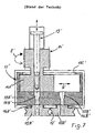
- FIG. 7 On the market, a generic pipe bending machine is known as in FIG. 7 is shown as prior art.
- this known pipe bending machine is driven by a toothed belt, not shown, long-toothed pivot pin used as the drive means 14 ', in which a pneumatically adjustable locking pin 15 'is mounted coaxially displaceable.
- a pneumatically adjustable locking pin 15 ' is mounted coaxially displaceable.
- One with the drive means 14 'rotatably connected pivot shaft 14 A' is designed as a rectangular block and also penetrated by the locking pin 15 '.
- the pivot shaft 14A ' together with a guide housing 17', a bed, which a lateral, ie transversely oriented to the pivot shaft displacement (double arrow D) 'of the pivot shaft 14A' together with the drive means 14 'with the aid of a guide slot 17C' allows.
- the rotational drive force (double arrow E ') on the guide housing 17' transferred, so that the entire guide housing 17 'is pivoted about the respective pivot axis about the respective drive axis.
- the pivot shaft 14A ' can be locked to a base plate 17A' of the guide housing 17 'by the locking bolt 15' in one or the other sliding position, so that during the bending process no displacement between the guide housing 17 'and the pivot shaft 14A' can take place.
- Coaxial with the guide bores 17B 'of the base plate 17A' are circular tube bending segments 12A 'and 12B' and their associated retaining pins 16A 'and 16B', respectively, and held relatively loosely in position relative to the guide housing 17 ', this position being maintained by the tapered free end of the guide Arresting pin 15 'is improved in the respective locking position.
- the tube to be bent is guided by the bending die 12 'between the circumferential half-grooves of the tube bending segments 12A'. Accordingly, in the bending process, the pipe bending segment which is not in the locked position, ie eccentrically to the drive 14 ', pivots about the pipe bending segment coaxially oriented with the drive device 14' and mechanically connected in a straight line.
- the invention has for its object to improve the bending behavior in a relatively simple construction of a generic pipe bending machine.
- This object is achieved by a tube bending machine having the features of claim 1 or 2 and by a method having the features of claim 10. Accordingly, it is provided in terms of the tube bending machine in the core that the pivot axes of the drive means each Rohrbiegesegmentes are arranged in the zero position coaxial with the bending radius of the other Rohrbiegesegmehtes and the coaxiality is left during each bending cut.
- the tube bending machine endlessly supplied, in itself straight tube feed strand is bendable once in a right bend and once in a left turn around the desired angle.
- This angle is usually 180 °, so that the highest possible pipe density per clamped pipe surface is achieved.
- the driven pivot axes of the two tube bending segments rotate in opposite directions during tube bending, wherein the one tube bending segment is in each case in its stationary to the drive shaft of the pivoting tube bending segment in a stationary, coaxial idle state. After each bending step, the previously pivoted tube bending segment is pivoted back to its zero position, the tube register preferably not displaced.
- a coaxial with him holding pin is provided on the drive side for each tube bending segment.
- the pipe holding pins of both pipe bending segments are connected by a respective pivotally connected to the pipe holding pin spacer element.
- the first drive device has a rigid first pivot arm between its pivot shaft and the retaining pin of the first pipe bending element, an optimum pivoting force transmission is thereby achieved.
- the second drive device has a rigid second pivot arm between its pivot shaft and the retaining pin of the second pipe bending element, which is rigidly connected to the pivot shaft of the second drive device, in particular by means of a clogging element, this results in a low-loss pivoting force transmission.
- the second pivot arm has a recess for pivoting in and out of the first holding pin of the first pipe bending element, then a very small, extremely stable pipe bending head can be realized thereby.
- a further disrupttechniksverêtung the pipe bending is achieved in that the pivot shafts of both pipe bending elements are pivotally mounted in a shaft holding body. This may include a distance variability of the two drive shafts
- the first pivot arm has a recess for pivoting in and out of the Verkopfungsijns the second drive means.
- the, z. B. when wearing the pipe bending elements or when changing to other pipe diameter or bending radii to be bent is required to simplify, consisting of two coupling points separation point between the pivot shafts, preferably the shaft holding body and the Schwenkkarmen provided.
- a distance adjuster for the pivot shafts allows a centering of the bending die on the exit point of the pipe straight holder and thus a Rohrbiege37 improving adjustment.
- the object with the features of claim 10 is achieved. Accordingly, it is provided to pivot the two pipe bending segments starting from a pipe feed aligned to the zero position alternately to the other pipe bending segment under bending of the pipe and after pivoting back (in Leerweg) of the initially bent under bending pipe bending segment the pipe on the pipe feed for the Next advance bending step sufficiently far and then to pivot the other pipe bending segment to the one pipe bending segment with simultaneous pipe bending back and then foundedzuschwenken back in the free path and to repeat this process for the production of further Rohrmeander.
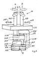
- a first pivot shaft 14A which is rotatable via the drive in an angle range between usually 0 ° and approximately 270 ° in both directions of rotation, is rotatably mounted in a shaft holding body 26 - as well as the drive train B, the pivot shaft 14B.
- Spacers 26A, 26B allow the lateral spacing of the parallel aligned ones To change the pivot shafts 14A / 14B, be it for adjustment or for bending radius adjustment.
- each drive train at a coupling point 24A and 24B is separable, so that the entire underlying bending head of the pipe bending machine can be replaced with another. This is required if the tube bending radii are to change.
- the pivot shaft 14A is closed, e.g. As shown approximately at right angles to a pivot arm 20A, the rotatable with the pivot shaft 14A, if necessary, separable as an interface, connected and a recess 25A ', to release movement space for the yet to be explained Verkröpfungselement 22.
- a retaining pin 16A which penetrates a spacer 18 in rotatable form and carries at its free end a first tube bending segment 12A.
- the retaining pin 16A may be rotatably attached to the free end of the pivot arm 20A and the retaining pin 16A rotatably or rotatably support the first tube bending segment 12A at its free end.
- the first (and also the second) tube bending segment 12A, 12B consist in the illustrated embodiment of a circular disc, each with a radially outer circumferential groove whose cross section corresponds in a known manner to be bent tube half diameter approximately.
- the pivot shaft 14A of the drive train A and the retaining pin 16B of the drive train B are in the in Fig. 1 shown zero position of the pipe bending machine coaxial arranged. The same applies to the pivot shaft 14B of the drive train B and the holding pin 16A of the drive train A.
- the operation is the following:
- the drive train B becomes active, wherein the drive device 14 rotates the pivot shaft 14B by, for example, 180 °.
- the Verkröpfungselement 22 moves into the recess 20A 'and the retaining pin 16B pivots the spacer member 18 together with the Rohrbiegesegmentes 12B in the counterclockwise direction by 180 ° around the Rohrbiegesegment 12A around and thus generates a 180 ° bend of the tube.
- the strand B pivots back by the same angle until the tube bending segment 12B has returned to its illustrated zero position when viewed from above.
- the tube to be bent can be further advanced through the bending die 12. This usually happens without rotation about the tube axis, but in principle can also be done with rotation about the tube axis.
- a further bending operation in particular a left bend can be performed.
- the drive device 14 pivots the pivot shaft 14A by a predetermined angle of, for example, 180 ° in the clockwise direction seen from above.
- the retaining pin 16A pivots the spacer element 18 together with the tube bending segment 12B around the second tube bending segment 12B.
- the drive train A travels in the free travel again by the bending angle in its zero position shown in the drawing. This completes a complete double bend cycle to produce a meander. This can be followed by further bending cycles in any way.
- FIGS. 1 to 5 illustrate the in FIG. 6 illustrated device in a practical embodiment.
- FIG. 1 illustrates the state of the pipe bending machine before the start of manufacturing a pipe mandrel 10 (see FIG. Fig. 3 ), wherein the bendable, in the direction of arrow C by a Rohrgeradehalter 28 displaceable tube is advanced as required by the bending die 12.
- FIG. 2 It can be seen how the tube bending segment 12B, starting from the in FIG. 1 shown zero position, in a bent by 180 ° bending position (in the drawing in the clockwise direction) is pivoted about the remaining in position other tube bending segment 12A and thus bent the tube to be bent around the tube bending segment 12A according to the predetermined bending contour by 180 ° ,
- FIG. 4 It is particularly clear how the two drive units 14 of the drive train A and B with respect to the shaft holding body 26 centered by Abstandversteller 26 A, 26 B with respect to the pipe straight holder 28 and can be adjusted in terms of spacing to produce larger or smaller Rohrbieger segments with other Rohrbiegesegmenten.
- FIG. 5 and 6 shows, inter alia, how a tool change can take place at the coupling points 24A, 24B.
- the pivot arms 20A, 20B of the pivot shafts 14A, 14B of the two drive trains A and B are separated.
Abstract
Description
Die Erfindung betrifft eine Rohrbiegemaschine für meandrierende Rohrverläufe, wie sie zum Beispiel im Bereich der Solar-Thermie als sonnenbestrahlte, von einem aufzuheizenden Fluid durchflossene Rohrmeander verwendet werden. Andere Anwendungsgebiete sind Fußbodenheizungen, Kühldecken oder Wärmeaustauschregister. Derartige Rohrbiegemaschinen weisen in der Regel zwei an das Rohrkaliber, d.h. den Rohrau-ßendurchmesser im wesentlichen angepasste Rohrbiegesegmente, welche unter Freilassen einer Biegematrize relativ zu einander verschwenkbar sind und das herzustellende Biegeprofil vorgeben.The invention relates to a pipe bending machine for meandering pipe courses, as used for example in the field of solar thermal energy as sun-irradiated, by a fluid to be heated by flowing Rohrmeander. Other applications include underfloor heating, cooling ceilings or heat exchange registers. Such tube bending machines usually have two to the tube caliber, i. the Rohrau ßendurchmesser substantially adapted pipe bending segments, which are free to pivot relative to each other while leaving a bending die and specify the bending profile to be produced.
Auf dem Markt ist eine gattungsgemäße Rohrbiegemaschine bekannt, wie sie in
Um eine Rohrbiegung mit entgegengesetztem Drehsinn zum Erzeugen einer meandrierenden Rohrmeander herzustellen, wird die vorbeschriebene Arretierung aufgehoben und der gesamte Antrieb 14' mit seiner Schwenkwelle 14A' bezüglich des Führungsgehäuses 17' quer verschoben und in der zweiten, nunmehr mit dem anderen Rohrbiegesegment koaxialen Arbeitsposition erneut verriegelt. - Diese bekannte Rohrbiegemaschine ist entsprechend aufwendig in der Handhabung und wegen des notwendigen Schiebespiels nicht allzu präzise und weniger robust wie dies zu wünschen wäre.In order to produce a pipe bend with opposite direction of rotation to produce a meandering Rohrmeander, the above lock is released and the entire drive 14 'with its
Der Erfindung liegt die Aufgabe zugrunde, bei einem vergleichsweise einfachen Aufbau einer gattungsgemäßen Rohrbiegemaschine das Biegeverhalten zu verbessern. Insbesondere ist es erwünscht, größere Maßhaltigkeit und geringere Anfälligkeit der Rohrbiegemaschine zu erreichen. Diese Aufgabe wird durch eine Rohrbiegemaschine mit den Merkmalen des Anspruchs 1 oder 2sowie durch ein Verfahren mit den Merkmalen des Anspruchs 10 gelöst. Demnach ist hinsichtlich der Rohrbiegemaschine im Kern vorgesehen, dass die Schwenkachsen der Antriebseinrichtungen jedes Rohrbiegesegmentes in Null-Stellung koaxial zum Biegeradius des jeweils anderen Rohrbiegesegmehtes angeordnet sind und die Koaxialität während jedes Biegeschnittes verlassen wird. Auf diese Weise ist es möglich, dass der der Rohrbiegemaschine endlos zugeführte, in sich gerade Rohrspeisestrang einmal in einer Rechtsbiegung und einmal in einer Linksbiegung um den gewünschten Winkel biegbar ist. Dieser Winkel liegt in der Regel bei 180°, so dass eine möglichst hohe Rohrdichte pro aufgespannter Rohrfläche erzielt wird. Demzufolge drehen sich die angetriebenen Schwenkachsen der beiden Rohrbiegesegmente beim Rohrbiegen gegenläufig, wobei sich das eine Rohrbiegesegment jeweils in seiner zur Antriebswelle des in Verschwenken begriffenen Rohrbiegesegmentes in einem stationären, koaxialen Ruhezustand befindet. Nach jedem Biegeschritt wird das zuvor verschwenkte Rohrbiegesegment in seine Null-Stellung zurückverschwenkt, wobei das Rohrregister sich vorzugsweise nicht verlagert. Auf diese Weise kann nach diesem Rückschwenken ein vorgebbarer Längenabschnitt des Rohres durch die Biegematrize gerade hindurch geschoben werden, bis der gerade verlaufende Teil der Registerlänge samt einer Bogenlänge nachgeführt ist. Erst dann beginnt ein neuer Rohrbiegeschritt in die zur ersten Biegerichtung entgegengesetzte zweite Biegerichtung. Bei jedem Biegeschritt wird das gerade Speisestück des noch nicht gebogenen Rohres in Position gehalten. Dies hat zur Folge, dass der Anfang des zu biegenden Rohrregisters bzw. das gesamte bereits gebogene Rohrregister um den Biegewinkel auf seiner Unter lage verschwenkt wird. Letzteres ist gebräuchlich und kann durch einen Schwenktisch erleichtert werden.The invention has for its object to improve the bending behavior in a relatively simple construction of a generic pipe bending machine. In particular, it is desirable to achieve greater dimensional accuracy and less susceptibility of the tube bending machine. This object is achieved by a tube bending machine having the features of claim 1 or 2 and by a method having the features of
Um jedes Rohrbiegesegment auf einfache Weise mit seinem zugehörigen Schwenkantrieb auf einfache Weise verbinden zu können, ist für jedes Rohrbiegesegment ein mit ihm koaxialer Haltezapfen antriebsseitig vorgesehen. Um die Maßhaltigkeit der zu biegenden Rohrregister zu verbessern, sind die Rohrhaltezapfen beider Rohrbiegesegmente durch ein mit den Rohrhaltezapfen jeweils schwenkbar verbundenes Abstandshalteelement verbunden.In order to easily connect each tube bending segment with its associated rotary actuator, a coaxial with him holding pin is provided on the drive side for each tube bending segment. In order to improve the dimensional accuracy of the pipe register to be bent, the pipe holding pins of both pipe bending segments are connected by a respective pivotally connected to the pipe holding pin spacer element.
Wenn die erste Antriebseinrichtung zwischen ihrer Schwenkwelle und dem Haltezapfen des ersten Rohrbiegeslementes einen starren ersten Schwenkarm aufweist, so wird dadurch eine optimale Schwenkkraftübertragung erreicht.If the first drive device has a rigid first pivot arm between its pivot shaft and the retaining pin of the first pipe bending element, an optimum pivoting force transmission is thereby achieved.
Wenn die zweite Antriebseinrichtung ein zwischen seiner Schwenkwelle und dem Haltezapfen des zweiten Rohrbiegeelementes einen starren zweiten Schwenkarm aufweist, der über ein Verkopfungselement mit der Schwenkwelle der zweiten Antriebseinrichung, insbesondere starr verbunden ist, so wird dadurch eine verlustarme Schwenkkraftübertragung erzielt.If the second drive device has a rigid second pivot arm between its pivot shaft and the retaining pin of the second pipe bending element, which is rigidly connected to the pivot shaft of the second drive device, in particular by means of a clogging element, this results in a low-loss pivoting force transmission.
Wenn der zweite Schwenkarm eine Aussparung zum Hinein- und Herausschwenken des ersten Haltezapfens des ersten Rohrbiegeelementes aufweist, so kann dadurch ein sehr klein bauender, äußerst stabiler Rohrbiegekopf verwirklicht werden.If the second pivot arm has a recess for pivoting in and out of the first holding pin of the first pipe bending element, then a very small, extremely stable pipe bending head can be realized thereby.
Eine weitere Maßhaltigkeitsverbesserung des Rohrbiegens wird dadurch erreicht, dass die Schwenkwellen beider Rohrbiegeelemente in einem Wellenhaltekörper schwenkgelagert sind. Dieser kann eine Abstandsveränderbarkeit der beiden Antriebswellen beinhaltenA further Maßhaltigkeitsverbesserung the pipe bending is achieved in that the pivot shafts of both pipe bending elements are pivotally mounted in a shaft holding body. This may include a distance variability of the two drive shafts
Das Gleiche gilt, wenn der erste Schwenkarm eine Aussparung zum Hinein- und Herausschwenken des Verkopfungselementes der zweiten Antriebseinrichtung aufweist.The same applies if the first pivot arm has a recess for pivoting in and out of the Verkopfungselementes the second drive means.
Um den Werkzeugwechsel zu vereinfachen, der, z. B. beim Verschleiß der Rohrbiegeelemente oder beim Wechsel auf andere zu biegende Rohrdurchmesser oder Biegeradien erforderlich ist, zu vereinfachen, ist eine aus zwei Kupplungsstellen bestehende Trennstelle zwischen den Schwenkwellen, vorzugsweise dem Wellenhaltekörper und den Schwenkkarmen vorgesehen.To simplify the tool change, the, z. B. when wearing the pipe bending elements or when changing to other pipe diameter or bending radii to be bent is required to simplify, consisting of two coupling points separation point between the pivot shafts, preferably the shaft holding body and the Schwenkkarmen provided.
Ein Rohrgeradehalter gestattet eine gezielte Zuführung des Rohrspeisestranges zur Biegematrize.A pipe straight holder allows a targeted feeding of the pipe feed strand to the bending die.
Ein Abstandsversteller für die Schwenkwellen gestattet eine Zentrierung der Biegematrize auf die Austrittsstelle des Rohrgeradehalters und somit eine die Rohrbiegequalität verbessernde Justage.A distance adjuster for the pivot shafts allows a centering of the bending die on the exit point of the pipe straight holder and thus a Rohrbiegequalität improving adjustment.
Hinsichtlich eines Verfahrens zum Herstellen von meandrierenden Rohrverläufen wird die Aufgabe mit den Merkmalen des Anspruchs 10 gelöst. Demnach ist vorgesehen, die beiden Rohrbiegesegmente ausgehend von einer auf die Rohrspeisestelle ausgerichtete Null-Stellung wechselseitig um das jeweils andere Rohrbiegesegment unter Biegen des Rohres zu verschwenken und nach Rückschwenken (im Leerweg) des zunächst unter Biegen hin verschwenkten Rohrbiegesegmentes das Rohr über die Rohrspeisestelle für den nächsten Biegeschritt ausreichend weit vorzuschieben und nachfolgend das andere Rohrbiegesegment um das eine Rohrbiegesegment unter gleichzeitigem Rohrbiegen hin zu verschwenken und anschließend wieder im Leerweg zurückzuschwenken und diesen Vorgang zum Herstellen weiterer Rohrmeander zu wiederholen.With regard to a method for producing meandering pipe runs, the object with the features of
Die vorgenannten sowie die beanspruchten und in den Ausführungsbeispielen beschriebenen erfindungsgemäß zu verwendenden Bauteile unterliegen in ihrer Größe, Formgestaltung, Materialauswahl und technischen Konzeption keinen besonderen Ausnahmebedingungen, so dass die in dem Anwendungsgebiet bekannten Auswahlkriterien uneingeschränkt Anwendung finden können.The above-mentioned and the claimed components to be used according to the invention described in the exemplary embodiments are not subject to special conditions of size, shape, material selection and technical design, so that the selection criteria known in the field of application can be used without restriction.
Weitere Einzelheiten, Merkmale und Vorteile des Gegenstandes der Erfindung ergeben sich aus den Unteransprüchen, sowie aus der nachfolgenden Beschreibung der zugehörigen Zeichnung und Tabelle, in der - beispielhaft - ein Ausführungsbeispiel einer Rohrbiegemaschine dargestellt ist.Further details, features and advantages of the subject matter of the invention will become apparent from the dependent claims, as well as from the following description of the accompanying drawings and table, in which - by way of example - an embodiment of a pipe bending machine is shown.
In der Zeichnung zeigen
- Fig. 1
- eine Rohrbiegemaschine in Ansicht von unten in Null-Stellung vor dem Biegen;
- Fig. 2
- dieselbe Rohrbiegemaschine in einer Biegestellung nach Vollenden einer Rechtsbiegung;
- Fig. 3
- dieselbe Rohrbiegemaschine in einer zweiten Biegestellung nach Vollenden einer Linksbiegung;
- Fig. 4
- dieselbe Rohrbiegemaschine in perspektivischer Ansicht von unten;
- Fig. 5
- dieselbe Rohrbiegemaschine in Seitenansicht;
- Fig. 6
- eine Prinzipdarstellung der Rohrbiegemaschine sowie
- Fig. 7
- eine Rohrbiegemaschine nach dem Stand der Technik.
- Fig. 1
- a pipe bending machine in bottom view in zero position before bending;
- Fig. 2
- the same tube bending machine in a bending position after completion of a right bend;
- Fig. 3
- the same tube bending machine in a second bending position after completion of a left bend;
- Fig. 4
- the same pipe bending machine in a perspective view from below;
- Fig. 5
- the same pipe bending machine in side view;
- Fig. 6
- a schematic diagram of the pipe bending machine as well
- Fig. 7
- a pipe bending machine according to the prior art.
Alle wesentlichen Elemente der Rohrbiegemaschine gehen aus der Prinzipdarstellung der
Auf der der Antriebseinrichtung 14 gegenüberliegenden Seite des Wellenhaltkörpers 26 ist jeder Antriebsstrang an einer Kupplungsstelle 24A bzw. 24B trennbar, so dass der ganze darunter liegende Biegekopf der Rohrbiegemaschine gegen einen anderen ausgetauscht werden kann. Dies ist erforderlich, wenn die Rohrbiegeradien sich ändern sollen.On the opposite side of the
An die Schwenkwelle 14A schließt sich z.B. wie dargestellt in etwa rechtwinklig ein Schwenkarm 20A an, der mit der Schwenkwelle 14A drehfest, als Schnittstelle ggf. trennbar, verbunden ist und eine Aussparung 25A' aufweist, um Bewegungsraum für das noch zu erläuternde Verkröpfungselement 22 freizulassen. Am freien Ende des Schwenkarmes 20A schließt sich etwa rechtwinklig und mit dem Schwenkarm 20A drehfest verbunden ein Haltezapfen 16A an, welcher ein Abstandselement 18 in drehbarer Form durchdringt und an seinem freien Ende ein erstes Rohrbiegesegment 12A trägt. Ebenso kann der Haltezapfen 16A mit dem freien Ende des Schwenkarms 20A drehbar befestigt sein und der Haltezapfen 16A an seinem freien Ende das erste Rohrbiegesegment 12A drehfest oder drehbar tragen. Das erste (und auch das zweite) Rohrbiegesegment 12A, 12B bestehen im dargestellten Ausführungsbeispiel aus einer Kreisscheibe mit je einer radial außen umlaufenden Nut, deren Querschnitt in bekannter Weise dem zu biegenden Rohrhalbdurchmesser in etwa entspricht.The
In ähnlicher Weise ist der zweite Antriebsstrang B aufgebaut, wobei sich an die Schwenkwelle 14B zunächst eine Verkröpfung 22 anschließt und die Aussparung 20B' des sich anschließenden Schwenkarmes 20B Raum für die Bewegung des Haltezapfens 16A des Antriebsstranges A freilassen.Similarly, the second drive train B is constructed, wherein the
Die Schwenkwelle 14A des Antriebsstranges A und der Haltezapfen 16B des Antriebsstranges B sind in den in
Wenn ein durch die Biegematrize 12 ausreichend weit vorgeschobenes zunächst gerades Rohrstück zu einem von oben gesehenen Linksbogen gebogen werden soll, wird der Antriebsstrang B tätig, wobei die Antriebseinrichtung 14 die Schwenkwelle 14B um z.B. 180° verdreht. Dabei verlagert sich das Verkröpfungselement 22 bis in die Aussparung 20A' und der Haltezapfen 16B verschwenkt das Abstandshalteelement 18 samt des Rohrbiegesegmentes 12B im Gegenuhrzeigersinn um 180° um das Rohrbiegesegment 12A herum und erzeugt damit eine 180° Biegung des Rohres. Nachfolgend schwenkt der Strang B wieder um denselben Winkel zurück, bis das Rohrbiegesegment 12B in von oben gesehenen seine dargestellten Null-Stellung zurückgekehrt ist. Danach kann das zu biegende Rohr weiter durch die Biegematrize 12 vorgeschoben werden. Dies geschieht in der Regel ohne Drehung um die Rohrachse, kann grundsätzlich aber auch mit Drehung um die Rohrachse erfolgen. Nachdem das eingespeiste noch gerade Rohr ausreichend weit vorgeschoben ist, kann ein weiterer Biegevorgang, insbesondere eine Linksbiegung durchgeführt werden. Hierzu verschwenkt der die Antriebseinrichtung 14, die Schwenkwelle 14A um einen vorgegebenen Winkel von z.B. 180° im von oben gesehenen Uhrzeigersinn. Dadurch verschwenkt der Haltezapfen 16A den das Abstandshalteelement 18 samt des Rohrbiegesegmentes 12B um das zweite Rohrbiegesegment 12B herum. Das dadurch sich erneut verbiegende Rohrende vollzieht diese Schwenkung mit. Im Anschluss an diesen zweiten Biegeschritt fährt der Antriebsstrang A im Leerweg wieder um den Biegewinkel in seinen in der Zeichnung dargestellte Null-Stellung zurück. Damit ist ein vollständiger Doppelbiegezyklus unter Erzeugung eines Meanders abgeschlossen. Hieran können sich weitere Biegezyklen in beliebiger Weise anschließen.If an initially straight pipe section pushed forward by the bending die 12 sufficiently far to be bent to a left-hand arc seen from above, the drive train B becomes active, wherein the
Die
Aus
Nach dem in
Aus
Aus
Während in den Zeichnungen von kreisrunden Rohrbiegesegmenten ausgegangen wird, deren Biegeform und Rohrbiegeradius in der Null-Stellung koaxial zur Schwenkwelle des jeweils anderen Antriebsstranges angeordnet sind, gestattet es die Erfindung grundsätzlich auch, Rohriegesegmente mit anderen Biegeformen und anderer Anordnung der Achse des Rohrbiegradius zu verwirklichen, wenn die beiden Antriebsstränge A, B entsprechend den Merkmalen von Anspruch 2 verwirklicht sind.While in the drawings of circular tube bending segments is assumed, the bending shape and tube bending radius are arranged in the zero position coaxial with the pivot shaft of the other drive train, the invention basically also allows to realize Rohriegesegmente with other bending shapes and other arrangement of the axis of Rohrbiegradius, when the two drive trains A, B are realized according to the features of claim 2.
- 1010
- RohrmeanderRohrmeander
- 10A10A
- Biegeprofilbending profile
- 10B10B
- Biegeprofilbending profile
- 1212
- Biegematrizebending die
- 12'12 '
- BiegmatrizeBiegmatrize
- 12A12A
- RohrbiegesegmentPipe bending segment
- 12A'12A '
- RohrbiegesegmentPipe bending segment
- 12B12B
- RohrbiegesegmentPipe bending segment
- 12B'12B '
- RohrbiegesegmentPipe bending segment
- 1414
- Antriebseinrichtungdriving means
- 14'14 '
- Antriebseinrichtungdriving means
- 14A14A
- Schwenkwellepivot shaft
- 14A'14A '
- Schwenkwellepivot shaft
- 14B14B
- Schwenkwellepivot shaft
- 15'15 '
- Arretierbolzenlocking pin
- 16A16A
- Haltezapfenretaining pins
- 16A'16A '
- Haltezapfenretaining pins
- 16B16B
- Haltezapfenretaining pins
- 16B'16B '
- Haltezapfenretaining pins
- 17'17 '
- Führungsgehäuseguide housing
- 17A'17A '
- Grundplattebaseplate
- 17B'17B '
- Führungsbohrungenguide bores
- 17C'17C '
- Führungskulisseguide link
- 1818
- AbstandshalteelementSpacer element
- 20A20A
- Schwenkarmswivel arm
- 20A'20A '
- Aussparungrecess
- 20B20B
- Schwenkarmswivel arm
- 20B'20B '
- Aussparungrecess
- 2222
- VerkröpfungselemeritVerkröpfungselemerit
- 24A24A
- Kupplungsstellecoupling site
- 24B24B
- Kupplungsstellecoupling site
- 2626
- WellehaltekörperShaft holding body
- 26A26A
- Abstandsverstellerdistance adjuster
- 26B26B
- Abstandsverstellerdistance adjuster
- 2828
- RohrgeradehalterPipe Corset
- AA
- Antriebsstrangpowertrain
- BB
- Antriebsstrangpowertrain
- CC
- Pfeilarrow
- D'D '
- Doppelpfeil (Verschiebung)Double arrow (shift)
- E'e '
- Doppelpfeil (Drehung)Double arrow (rotation)
- FF
- Doppelpfeil (Verschwenkung)Double arrow (swiveling)
- GG
- Doppelpfeil (Verschwenkung)Double arrow (swiveling)
- RARA
- Biegeradius .Bending radius.
- RBRB
- Biegeradiusbending radius
Claims (10)
dadurch gekennzeichnet,
dass jedes Rohrbiegesegment (12A; 12B) mit einem gesonderten Antriebsstrang (A) und (B) versehen ist,
dass in einer Null-Stellung die Achse der Schwenkwelle (14A) des ersten Antriebsstranges (A) koaxial zum Biegeradius (RB) des zweiten Biegesegmentes (12B) und die Schwenkwelle (14B) des zweiten Antriebsstranges (B) koaxial zum Biegeradius (RA) des ersten Rohrbiegesegmentes (12A) angeordnet sind und
dass die Koaxialität der Null-Stellung bei jedem Verschwenken einer der der Schwenkwellen (14A, 14B) in eine Biegestellung des jeweils verschwenkten Rohrbiegesegmentes aufgehoben ist.Pipe bending machine for meandering pipe runs (10) having at least two tube bending segments (12A, 12B) which are substantially adapted to the tube caliber and allow a bending die (12) to be pivoted relative to one another, which predetermines the bending profile (10A, 10B) and a drive device (14). for separate pivoting of both tube bending segments,
characterized,
in that each tube bending segment (12A, 12B) is provided with a separate drive train (A) and (B),
that in a zero position, the axis of the pivot shaft (14A) of the first drive train (A) coaxial with the bending radius (RB) of the second bending segment (12B) and the pivot shaft (14B) of the second drive train (B) coaxial with the bending radius (RA) of first pipe bending segment (12A) are arranged and
that the coaxiality of the zero position at each pivoting of one of the pivot shafts (14A, 14B) is canceled in a bending position of the respective pivoted Rohrbiegesegmentes.
dass jedes Rohrbiegesegment (12A; 12B) mit einem gesonderten Antriebsstrang (A) und (B) versehen ist und
dass der erste Antriebsstrang (A) zwischen seiner Schwenkwelle (14A) und einem Haltezapfen (16A) des ersten Rohrbiegeelementes (12A) einen ersten Schwenkarm (20A) und der zweite Antriebsstrang (B) zwischen seiner Schwenkwelle (14B) und einem Haltezapfen (16B) des zweiten Rohrbiegesegmentes (12B) einen über ein Verkröpfungselement (22) mit der zweiten Schwenkwelle (14B) des zweiten Antriebsstranges (B) verbundenen zweiten Schwenkarm (20B) aufweist.Pipe bending machine according to the preamble of claim 1, in particular claim 1, characterized
that each tube bending segment (12A, 12B) is provided with a separate drive train (A) and (B), and
that the first drive train (A) between its pivot shaft (14A) and a retaining pin (16A) of the first pipe bending element (12A) has a first Swing arm (20A) and the second drive train (B) between its pivot shaft (14B) and a retaining pin (16B) of the second Rohrbiegesegmentes (12B) via a crank member (22) with the second pivot shaft (14B) of the second drive train (B) second pivot arm (20B).
dadurch gekennzeichnet, dass
jedes Rohrbiegesegment von einem gesonderten Antriebsstrang wahlweise verschwenkt wird, wobei eine in einer Null-Stellung vorhandene Koaxialität zwischen den Schwenkwellen der Antriebsstränge mit dem Biegeradius des Rohrbiegesegmentes des jeweils anderen Antriebsstranges für das jeweils verschwenkte Rohrbiegesegment in den Biege-Stellungen aufgehoben wird, und wobei das eine oder das andere Rohrbiegesegment, ausgehend von der auf eine Rohrspeisestelle ausgerichteten Null-Stellung, wechselseitig von dem ihm zugeordnetem Antriebsstrang um das jeweils andere Rohrbiegesegment unter Biegen des Rohres verschwenkt wird und nach Rückschwenken (im Leerweg) des zunächst unter Biegen hin verschwenkten einen Rohrbiegesegments das Rohr über die Rohrspeisestelle für den nächsten Biegeschritt ausreichend weit vorgeschoben und nachfolgend das andere Rohrbiegesegment von seinem ihm zugeordneten Antriebsstränge um das eine Rohrbiegsegment unter gleichzeitigem Rohrbiegen hin verschwenkt wird und anschließend wieder (im Leerweg) zurückverschwenkt wird und diese Schritte zum Herstellen weiterer Rohrmeander Im Bedarfsfall wiederholt werden.DB = EPODOC & ... PN = EP0284301 A method of producing circumferential pipe runs with at least two tube bending segments (12A, 12B) which are substantially adapted to the tube caliber and which are capable of pivoting reactively with respect to one another, leaving the bending profile (10A, 10B) free, and with a drive device (14) for the separate pivoting of the tube bending segments, both tube bending segments,
characterized in that
each Rohrbiegesegment is selectively pivoted by a separate drive train, wherein a present in a zero position coaxiality between the pivot shafts of the drive trains is repealed with the bending radius of the pipe bending segment of the other drive train for each pivoted Rohrbiegesegment in the bending positions, and wherein the one or the other pipe bending segment, starting from the aligned to a pipe feeding zero position, mutually pivoted by the associated drive train to the other pipe bending segment bending the pipe and after pivoting back (in the free path) of the initially bent under bending a Rohrbiegesegments the pipe over the pipe feeding point for the next bending step advanced far enough and subsequently the other pipe bending segment is pivoted by its associated drive trains to a pipe bending segment with simultaneous tube bending and is then swung back again (in Leerweg) and these steps for making further pipe mandrels are repeated if necessary.
Priority Applications (3)
| Application Number | Priority Date | Filing Date | Title |
|---|---|---|---|
| AT06025676T ATE423639T1 (en) | 2006-12-12 | 2006-12-12 | TUBE BENDING MACHINE FOR PRODUCING MEANDERING TUBE ROUTES AND METHOD FOR PRODUCING MEANDERING PIPE ROUTES |
| DE502006002973T DE502006002973D1 (en) | 2006-12-12 | 2006-12-12 | Pipe bending machine for the production of meandering pipe runs and method for producing meandering pipe runs |
| EP06025676A EP1932603B1 (en) | 2006-12-12 | 2006-12-12 | Pipe bending machine for manufacturing meandering pipes and method for manufacturing meandering pipes |
Applications Claiming Priority (1)
| Application Number | Priority Date | Filing Date | Title |
|---|---|---|---|
| EP06025676A EP1932603B1 (en) | 2006-12-12 | 2006-12-12 | Pipe bending machine for manufacturing meandering pipes and method for manufacturing meandering pipes |
Publications (2)
| Publication Number | Publication Date |
|---|---|
| EP1932603A1 true EP1932603A1 (en) | 2008-06-18 |
| EP1932603B1 EP1932603B1 (en) | 2009-02-25 |
Family
ID=37682889
Family Applications (1)
| Application Number | Title | Priority Date | Filing Date |
|---|---|---|---|
| EP06025676A Active EP1932603B1 (en) | 2006-12-12 | 2006-12-12 | Pipe bending machine for manufacturing meandering pipes and method for manufacturing meandering pipes |
Country Status (3)
| Country | Link |
|---|---|
| EP (1) | EP1932603B1 (en) |
| AT (1) | ATE423639T1 (en) |
| DE (1) | DE502006002973D1 (en) |
Cited By (4)
| Publication number | Priority date | Publication date | Assignee | Title |
|---|---|---|---|---|
| US20130025339A1 (en) * | 2011-07-26 | 2013-01-31 | Medtronic Vascular, Inc. | Apparatus and Method for Forming a Wave Form for a Stent from a Wire |
| DE102012019183A1 (en) * | 2012-09-28 | 2014-04-03 | Ulrich Zimmer | Device for bending pipe material, particularly brake lines or fuel lines, has hinge bending head pivotally mounted at bending tower and intermediate gear mounted on pivotal receiving lever of hinge bending head |
| CN113894190A (en) * | 2021-10-11 | 2022-01-07 | 马鞍山市润通重工科技有限公司 | Large sleeve pipe bending equipment and implementation method thereof |
| CN113894190B (en) * | 2021-10-11 | 2024-04-30 | 马鞍山市润通重工科技有限公司 | Large-sleeve pipe bending equipment and implementation method thereof |
Citations (6)
| Publication number | Priority date | Publication date | Assignee | Title |
|---|---|---|---|---|
| FR2125193A1 (en) * | 1971-02-18 | 1972-09-29 | Gol Sp Kon | Coiled tube mfr - by a high-performance machine employing two drive shafts |
| JPS4893571A (en) * | 1972-03-11 | 1973-12-04 | ||
| DE2236898A1 (en) | 1972-07-27 | 1974-02-07 | Stiebel Eltron Gmbh & Co Kg | Bending tubes for heat exchangers - using machine with two grooved bending rolls side by side |
| DE2918813A1 (en) * | 1979-05-10 | 1980-11-20 | Brueninghaus Gmbh Stahlwerke | Bending machine for metal bars or tubes - has horizontally movable pillars supporting respective anvils on which workpiece is bent via rollers on lever arms |
| JPS6160218A (en) * | 1984-08-30 | 1986-03-27 | Sanden Corp | Apparatus for producing zigzag pipe |
| FR2685228A1 (en) * | 1991-12-23 | 1993-06-25 | Automation Franc | Machine for bending a rod-, bar-, tube-, wire- or similar-type element |
-
2006
- 2006-12-12 DE DE502006002973T patent/DE502006002973D1/en active Active
- 2006-12-12 AT AT06025676T patent/ATE423639T1/en active
- 2006-12-12 EP EP06025676A patent/EP1932603B1/en active Active
Patent Citations (6)
| Publication number | Priority date | Publication date | Assignee | Title |
|---|---|---|---|---|
| FR2125193A1 (en) * | 1971-02-18 | 1972-09-29 | Gol Sp Kon | Coiled tube mfr - by a high-performance machine employing two drive shafts |
| JPS4893571A (en) * | 1972-03-11 | 1973-12-04 | ||
| DE2236898A1 (en) | 1972-07-27 | 1974-02-07 | Stiebel Eltron Gmbh & Co Kg | Bending tubes for heat exchangers - using machine with two grooved bending rolls side by side |
| DE2918813A1 (en) * | 1979-05-10 | 1980-11-20 | Brueninghaus Gmbh Stahlwerke | Bending machine for metal bars or tubes - has horizontally movable pillars supporting respective anvils on which workpiece is bent via rollers on lever arms |
| JPS6160218A (en) * | 1984-08-30 | 1986-03-27 | Sanden Corp | Apparatus for producing zigzag pipe |
| FR2685228A1 (en) * | 1991-12-23 | 1993-06-25 | Automation Franc | Machine for bending a rod-, bar-, tube-, wire- or similar-type element |
Cited By (6)
| Publication number | Priority date | Publication date | Assignee | Title |
|---|---|---|---|---|
| US20130025339A1 (en) * | 2011-07-26 | 2013-01-31 | Medtronic Vascular, Inc. | Apparatus and Method for Forming a Wave Form for a Stent from a Wire |
| US9296034B2 (en) * | 2011-07-26 | 2016-03-29 | Medtronic Vascular, Inc. | Apparatus and method for forming a wave form for a stent from a wire |
| US10518315B2 (en) | 2011-07-26 | 2019-12-31 | Medtronic Vascular, Inc. | Apparatus and method for forming a wave form for a stent from a wire |
| DE102012019183A1 (en) * | 2012-09-28 | 2014-04-03 | Ulrich Zimmer | Device for bending pipe material, particularly brake lines or fuel lines, has hinge bending head pivotally mounted at bending tower and intermediate gear mounted on pivotal receiving lever of hinge bending head |
| CN113894190A (en) * | 2021-10-11 | 2022-01-07 | 马鞍山市润通重工科技有限公司 | Large sleeve pipe bending equipment and implementation method thereof |
| CN113894190B (en) * | 2021-10-11 | 2024-04-30 | 马鞍山市润通重工科技有限公司 | Large-sleeve pipe bending equipment and implementation method thereof |
Also Published As
| Publication number | Publication date |
|---|---|
| DE502006002973D1 (en) | 2009-04-09 |
| EP1932603B1 (en) | 2009-02-25 |
| ATE423639T1 (en) | 2009-03-15 |
Similar Documents
| Publication | Publication Date | Title |
|---|---|---|
| EP2879823A1 (en) | Machine for machining pipe ends, having a centering device for centering a tubular workpiece in relation to an axis of rotation | |
| EP0300959B1 (en) | Process and apparatus for centering a pilot arbor | |
| DE102004060766C5 (en) | Bending device for pipes | |
| DE4323009C2 (en) | Device for generating the pitch of a spring in a spring wind device | |
| EP0079587A1 (en) | Wire-bending machine | |
| DE2523831C3 (en) | Device for straightening wire | |
| DE102007049547A1 (en) | Compound filter producing machine for reducing poisonous effects of cigarette smoke, has rotary drum including adjusting device adjusting position of rotational axis of fittings based on rotational axis of rotary drum | |
| DE3644251C2 (en) | ||
| EP3645188A1 (en) | Method for producing a bent part and bending machine for performing the method | |
| DE19816403C2 (en) | Wire forming device with a wire brake device and wire forming method | |
| DE3423706A1 (en) | DEVICE FOR CONTINUOUS STEEL TUBE PRODUCTION | |
| DE102011014953B4 (en) | Bending device for rod and tubular workpieces | |
| EP1932603B1 (en) | Pipe bending machine for manufacturing meandering pipes and method for manufacturing meandering pipes | |
| DE102016116159B4 (en) | Method and device for bending strand-like workpieces | |
| EP0561025B1 (en) | Device for bending tubes, in particular for making serpentine-shaped tubes | |
| EP3116680B1 (en) | Device and method for producing a functional shaft | |
| DE602005002579T2 (en) | Machine for bending bars | |
| DE102016101908B4 (en) | Apparatus and method for bending pipes | |
| DE202004011947U1 (en) | Device for bending pipes used e.g. in the production of brake and fuel lines in the motor vehicle construction industry comprises two parallel pipe-bending stations, and a pipe transfer device | |
| DE2419231C3 (en) | Device for incremental grid transport by different amounts in a grid welding machine | |
| DE2420584C3 (en) | Winding machine for tape material or the like. | |
| EP3581291B1 (en) | Sheet metal bending machine with variable roller geometry | |
| DE1959160A1 (en) | Method and device for corrugating pipes | |
| DE2319092B2 (en) | Automatic brush mfg. machine - has two support plates, rotating on central shaft, with levers | |
| AT228035B (en) | Machine for continuously shaping wire into articles having sections of different predetermined shapes |
Legal Events
| Date | Code | Title | Description |
|---|---|---|---|
| PUAI | Public reference made under article 153(3) epc to a published international application that has entered the european phase |
Free format text: ORIGINAL CODE: 0009012 |
|
| 17P | Request for examination filed |
Effective date: 20080115 |
|
| AK | Designated contracting states |
Kind code of ref document: A1 Designated state(s): AT BE BG CH CY CZ DE DK EE ES FI FR GB GR HU IE IS IT LI LT LU LV MC NL PL PT RO SE SI SK TR |
|
| AX | Request for extension of the european patent |
Extension state: AL BA HR MK RS |
|
| GRAP | Despatch of communication of intention to grant a patent |
Free format text: ORIGINAL CODE: EPIDOSNIGR1 |
|
| GRAS | Grant fee paid |
Free format text: ORIGINAL CODE: EPIDOSNIGR3 |
|
| GRAA | (expected) grant |
Free format text: ORIGINAL CODE: 0009210 |
|
| AK | Designated contracting states |
Kind code of ref document: B1 Designated state(s): AT BE BG CH CY CZ DE DK EE ES FI FR GB GR HU IE IS IT LI LT LU LV MC NL PL PT RO SE SI SK TR |
|
| REG | Reference to a national code |
Ref country code: GB Ref legal event code: FG4D Free format text: NOT ENGLISH |
|
| REG | Reference to a national code |
Ref country code: CH Ref legal event code: EP |
|
| REG | Reference to a national code |
Ref country code: IE Ref legal event code: FG4D Free format text: LANGUAGE OF EP DOCUMENT: GERMAN |
|
| REF | Corresponds to: |
Ref document number: 502006002973 Country of ref document: DE Date of ref document: 20090409 Kind code of ref document: P |
|
| REG | Reference to a national code |
Ref country code: GR Ref legal event code: EP Ref document number: 20090401023 Country of ref document: GR |
|
| PG25 | Lapsed in a contracting state [announced via postgrant information from national office to epo] |
Ref country code: SI Free format text: LAPSE BECAUSE OF FAILURE TO SUBMIT A TRANSLATION OF THE DESCRIPTION OR TO PAY THE FEE WITHIN THE PRESCRIBED TIME-LIMIT Effective date: 20090225 Ref country code: LT Free format text: LAPSE BECAUSE OF FAILURE TO SUBMIT A TRANSLATION OF THE DESCRIPTION OR TO PAY THE FEE WITHIN THE PRESCRIBED TIME-LIMIT Effective date: 20090225 Ref country code: FI Free format text: LAPSE BECAUSE OF FAILURE TO SUBMIT A TRANSLATION OF THE DESCRIPTION OR TO PAY THE FEE WITHIN THE PRESCRIBED TIME-LIMIT Effective date: 20090225 |
|
| PG25 | Lapsed in a contracting state [announced via postgrant information from national office to epo] |
Ref country code: SE Free format text: LAPSE BECAUSE OF FAILURE TO SUBMIT A TRANSLATION OF THE DESCRIPTION OR TO PAY THE FEE WITHIN THE PRESCRIBED TIME-LIMIT Effective date: 20090525 Ref country code: PL Free format text: LAPSE BECAUSE OF FAILURE TO SUBMIT A TRANSLATION OF THE DESCRIPTION OR TO PAY THE FEE WITHIN THE PRESCRIBED TIME-LIMIT Effective date: 20090225 Ref country code: LV Free format text: LAPSE BECAUSE OF FAILURE TO SUBMIT A TRANSLATION OF THE DESCRIPTION OR TO PAY THE FEE WITHIN THE PRESCRIBED TIME-LIMIT Effective date: 20090225 Ref country code: IS Free format text: LAPSE BECAUSE OF FAILURE TO SUBMIT A TRANSLATION OF THE DESCRIPTION OR TO PAY THE FEE WITHIN THE PRESCRIBED TIME-LIMIT Effective date: 20090625 |
|
| REG | Reference to a national code |
Ref country code: IE Ref legal event code: FD4D |
|
| PG25 | Lapsed in a contracting state [announced via postgrant information from national office to epo] |
Ref country code: PT Free format text: LAPSE BECAUSE OF FAILURE TO SUBMIT A TRANSLATION OF THE DESCRIPTION OR TO PAY THE FEE WITHIN THE PRESCRIBED TIME-LIMIT Effective date: 20090812 Ref country code: IE Free format text: LAPSE BECAUSE OF FAILURE TO SUBMIT A TRANSLATION OF THE DESCRIPTION OR TO PAY THE FEE WITHIN THE PRESCRIBED TIME-LIMIT Effective date: 20090225 Ref country code: ES Free format text: LAPSE BECAUSE OF FAILURE TO SUBMIT A TRANSLATION OF THE DESCRIPTION OR TO PAY THE FEE WITHIN THE PRESCRIBED TIME-LIMIT Effective date: 20090605 Ref country code: EE Free format text: LAPSE BECAUSE OF FAILURE TO SUBMIT A TRANSLATION OF THE DESCRIPTION OR TO PAY THE FEE WITHIN THE PRESCRIBED TIME-LIMIT Effective date: 20090225 Ref country code: DK Free format text: LAPSE BECAUSE OF FAILURE TO SUBMIT A TRANSLATION OF THE DESCRIPTION OR TO PAY THE FEE WITHIN THE PRESCRIBED TIME-LIMIT Effective date: 20090225 Ref country code: CZ Free format text: LAPSE BECAUSE OF FAILURE TO SUBMIT A TRANSLATION OF THE DESCRIPTION OR TO PAY THE FEE WITHIN THE PRESCRIBED TIME-LIMIT Effective date: 20090225 |
|
| PG25 | Lapsed in a contracting state [announced via postgrant information from national office to epo] |
Ref country code: SK Free format text: LAPSE BECAUSE OF FAILURE TO SUBMIT A TRANSLATION OF THE DESCRIPTION OR TO PAY THE FEE WITHIN THE PRESCRIBED TIME-LIMIT Effective date: 20090225 Ref country code: RO Free format text: LAPSE BECAUSE OF FAILURE TO SUBMIT A TRANSLATION OF THE DESCRIPTION OR TO PAY THE FEE WITHIN THE PRESCRIBED TIME-LIMIT Effective date: 20090225 |
|
| PLBE | No opposition filed within time limit |
Free format text: ORIGINAL CODE: 0009261 |
|
| STAA | Information on the status of an ep patent application or granted ep patent |
Free format text: STATUS: NO OPPOSITION FILED WITHIN TIME LIMIT |
|
| PG25 | Lapsed in a contracting state [announced via postgrant information from national office to epo] |
Ref country code: BG Free format text: LAPSE BECAUSE OF FAILURE TO SUBMIT A TRANSLATION OF THE DESCRIPTION OR TO PAY THE FEE WITHIN THE PRESCRIBED TIME-LIMIT Effective date: 20090525 |
|
| 26N | No opposition filed |
Effective date: 20091126 |
|
| BERE | Be: lapsed |
Owner name: REIMANN, PETER Effective date: 20091231 |
|
| PG25 | Lapsed in a contracting state [announced via postgrant information from national office to epo] |
Ref country code: MC Free format text: LAPSE BECAUSE OF NON-PAYMENT OF DUE FEES Effective date: 20100701 |
|
| PG25 | Lapsed in a contracting state [announced via postgrant information from national office to epo] |
Ref country code: BE Free format text: LAPSE BECAUSE OF NON-PAYMENT OF DUE FEES Effective date: 20091231 |
|
| PG25 | Lapsed in a contracting state [announced via postgrant information from national office to epo] |
Ref country code: LU Free format text: LAPSE BECAUSE OF NON-PAYMENT OF DUE FEES Effective date: 20091212 |
|
| PGRI | Patent reinstated in contracting state [announced from national office to epo] |
Ref country code: IT Effective date: 20110501 |
|
| PG25 | Lapsed in a contracting state [announced via postgrant information from national office to epo] |
Ref country code: HU Free format text: LAPSE BECAUSE OF FAILURE TO SUBMIT A TRANSLATION OF THE DESCRIPTION OR TO PAY THE FEE WITHIN THE PRESCRIBED TIME-LIMIT Effective date: 20090826 |
|
| REG | Reference to a national code |
Ref country code: CH Ref legal event code: PL |
|
| PG25 | Lapsed in a contracting state [announced via postgrant information from national office to epo] |
Ref country code: CY Free format text: LAPSE BECAUSE OF FAILURE TO SUBMIT A TRANSLATION OF THE DESCRIPTION OR TO PAY THE FEE WITHIN THE PRESCRIBED TIME-LIMIT Effective date: 20090225 |
|
| PG25 | Lapsed in a contracting state [announced via postgrant information from national office to epo] |
Ref country code: CH Free format text: LAPSE BECAUSE OF NON-PAYMENT OF DUE FEES Effective date: 20101231 Ref country code: LI Free format text: LAPSE BECAUSE OF NON-PAYMENT OF DUE FEES Effective date: 20101231 |
|
| REG | Reference to a national code |
Ref country code: FR Ref legal event code: PLFP Year of fee payment: 10 |
|
| REG | Reference to a national code |
Ref country code: FR Ref legal event code: PLFP Year of fee payment: 11 |
|
| REG | Reference to a national code |
Ref country code: FR Ref legal event code: PLFP Year of fee payment: 12 |
|
| PGFP | Annual fee paid to national office [announced via postgrant information from national office to epo] |
Ref country code: FR Payment date: 20171219 Year of fee payment: 12 Ref country code: TR Payment date: 20171211 Year of fee payment: 12 |
|
| PGFP | Annual fee paid to national office [announced via postgrant information from national office to epo] |
Ref country code: GB Payment date: 20171221 Year of fee payment: 12 Ref country code: IT Payment date: 20171218 Year of fee payment: 12 Ref country code: GR Payment date: 20171218 Year of fee payment: 12 |
|
| GBPC | Gb: european patent ceased through non-payment of renewal fee |
Effective date: 20181212 |
|
| PG25 | Lapsed in a contracting state [announced via postgrant information from national office to epo] |
Ref country code: FR Free format text: LAPSE BECAUSE OF NON-PAYMENT OF DUE FEES Effective date: 20181231 Ref country code: IT Free format text: LAPSE BECAUSE OF NON-PAYMENT OF DUE FEES Effective date: 20181212 |
|
| PG25 | Lapsed in a contracting state [announced via postgrant information from national office to epo] |
Ref country code: GR Free format text: LAPSE BECAUSE OF NON-PAYMENT OF DUE FEES Effective date: 20190702 |
|
| PG25 | Lapsed in a contracting state [announced via postgrant information from national office to epo] |
Ref country code: GB Free format text: LAPSE BECAUSE OF NON-PAYMENT OF DUE FEES Effective date: 20181212 |
|
| PGFP | Annual fee paid to national office [announced via postgrant information from national office to epo] |
Ref country code: NL Payment date: 20191217 Year of fee payment: 14 |
|
| PGFP | Annual fee paid to national office [announced via postgrant information from national office to epo] |
Ref country code: AT Payment date: 20191213 Year of fee payment: 14 |
|
| REG | Reference to a national code |
Ref country code: NL Ref legal event code: MM Effective date: 20210101 |
|
| REG | Reference to a national code |
Ref country code: AT Ref legal event code: MM01 Ref document number: 423639 Country of ref document: AT Kind code of ref document: T Effective date: 20201212 |
|
| PG25 | Lapsed in a contracting state [announced via postgrant information from national office to epo] |
Ref country code: NL Free format text: LAPSE BECAUSE OF NON-PAYMENT OF DUE FEES Effective date: 20210101 |
|
| PG25 | Lapsed in a contracting state [announced via postgrant information from national office to epo] |
Ref country code: AT Free format text: LAPSE BECAUSE OF NON-PAYMENT OF DUE FEES Effective date: 20201212 |
|
| PG25 | Lapsed in a contracting state [announced via postgrant information from national office to epo] |
Ref country code: TR Free format text: LAPSE BECAUSE OF NON-PAYMENT OF DUE FEES Effective date: 20181212 |
|
| PGFP | Annual fee paid to national office [announced via postgrant information from national office to epo] |
Ref country code: DE Payment date: 20230228 Year of fee payment: 17 |