EP1920731A2 - Device for holding a model - Google Patents
Device for holding a model Download PDFInfo
- Publication number
- EP1920731A2 EP1920731A2 EP20070021489 EP07021489A EP1920731A2 EP 1920731 A2 EP1920731 A2 EP 1920731A2 EP 20070021489 EP20070021489 EP 20070021489 EP 07021489 A EP07021489 A EP 07021489A EP 1920731 A2 EP1920731 A2 EP 1920731A2
- Authority
- EP
- European Patent Office
- Prior art keywords
- model
- holding
- dental prosthesis
- shape
- region
- Prior art date
- Legal status (The legal status is an assumption and is not a legal conclusion. Google has not performed a legal analysis and makes no representation as to the accuracy of the status listed.)
- Granted
Links
- 238000000034 method Methods 0.000 claims abstract description 25
- 238000004519 manufacturing process Methods 0.000 claims description 5
- 238000011156 evaluation Methods 0.000 claims description 3
- 238000001459 lithography Methods 0.000 claims description 3
- 238000003801 milling Methods 0.000 claims description 3
- 239000011324 bead Substances 0.000 claims 1
- 239000007943 implant Substances 0.000 description 4
- 239000000919 ceramic Substances 0.000 description 1
- 229910002110 ceramic alloy Inorganic materials 0.000 description 1
- 238000011157 data evaluation Methods 0.000 description 1
- 238000001514 detection method Methods 0.000 description 1
- PCHJSUWPFVWCPO-UHFFFAOYSA-N gold Chemical compound [Au] PCHJSUWPFVWCPO-UHFFFAOYSA-N 0.000 description 1
- 239000010931 gold Substances 0.000 description 1
- 229910052737 gold Inorganic materials 0.000 description 1
- 238000003780 insertion Methods 0.000 description 1
- 230000037431 insertion Effects 0.000 description 1
- 230000014759 maintenance of location Effects 0.000 description 1
- 239000003550 marker Substances 0.000 description 1
- 239000002184 metal Substances 0.000 description 1
- 229910052751 metal Inorganic materials 0.000 description 1
- 229910001092 metal group alloy Inorganic materials 0.000 description 1
- 230000003287 optical effect Effects 0.000 description 1
- 229920003023 plastic Polymers 0.000 description 1
- 239000004033 plastic Substances 0.000 description 1
- NTHWMYGWWRZVTN-UHFFFAOYSA-N sodium silicate Chemical compound [Na+].[Na+].[O-][Si]([O-])=O NTHWMYGWWRZVTN-UHFFFAOYSA-N 0.000 description 1
Images


Classifications
-
- A—HUMAN NECESSITIES
- A61—MEDICAL OR VETERINARY SCIENCE; HYGIENE
- A61C—DENTISTRY; APPARATUS OR METHODS FOR ORAL OR DENTAL HYGIENE
- A61C13/00—Dental prostheses; Making same
- A61C13/0027—Base for holding castings
-
- A—HUMAN NECESSITIES
- A61—MEDICAL OR VETERINARY SCIENCE; HYGIENE
- A61C—DENTISTRY; APPARATUS OR METHODS FOR ORAL OR DENTAL HYGIENE
- A61C13/00—Dental prostheses; Making same
- A61C13/12—Tools for fastening artificial teeth; Holders, clamps, or stands for artificial teeth
-
- A—HUMAN NECESSITIES
- A61—MEDICAL OR VETERINARY SCIENCE; HYGIENE
- A61C—DENTISTRY; APPARATUS OR METHODS FOR ORAL OR DENTAL HYGIENE
- A61C9/00—Impression cups, i.e. impression trays; Impression methods
- A61C9/004—Means or methods for taking digitized impressions
- A61C9/0093—Workpiece support
-
- Y—GENERAL TAGGING OF NEW TECHNOLOGICAL DEVELOPMENTS; GENERAL TAGGING OF CROSS-SECTIONAL TECHNOLOGIES SPANNING OVER SEVERAL SECTIONS OF THE IPC; TECHNICAL SUBJECTS COVERED BY FORMER USPC CROSS-REFERENCE ART COLLECTIONS [XRACs] AND DIGESTS
- Y10—TECHNICAL SUBJECTS COVERED BY FORMER USPC
- Y10T—TECHNICAL SUBJECTS COVERED BY FORMER US CLASSIFICATION
- Y10T29/00—Metal working
- Y10T29/49—Method of mechanical manufacture
- Y10T29/49567—Dental appliance making
Definitions
- the invention relates to a device for holding a model of a tooth replacement part, a device for scanning objects, a method for creating a digital model of a tooth replacement part as well as an associated data carrier and a method for producing a tooth replacement part.
- An abutment is a part of a dental care that is placed on an implant, e.g. is screwed on.
- a crown or bridge or other can be placed on the abutment.
- standard abutments are used which are adapted or assigned to a corresponding implant.
- the object of the present invention is to specify means and methods with which an automated production of individual abutments or other tooth replacement parts is made possible. This object is achieved with a device for holding according to claim 1, an apparatus for scanning objects according to claim 10, a method for creating a digital model of a dental prosthesis according to claim 11, a method of manufacturing a dental prosthesis according to claim 16 and a computer-readable medium Claim 17. Preferred embodiments are disclosed in the subclaims.
- the device for holding a model of a dental prosthetic item has two areas. On the first area, the model of a dental prosthesis can be modeled or a corresponding model can be placed.
- the second area allows a unique location identification of the device for holding.
- the second area is preferably not covered by the model of the tooth replacement part, so that this second area remains optically accessible.
- Such a model of a dental prosthesis part can be modeled, for example, from wax, whereby a light, fast and individual as well as well-known modeling can be used.
- the device for holding is preferably dimensioned such that it can have only one model of a tooth replacement part that can be associated with a single tooth, such as an abutment that belongs to exactly one implant (instead of one tooth).
- the position of the device can be detected to hold. If the position of the device for holding known, so that the location of the first area is known. Since the model is modeled or placed on the first area, by determining the outer shape of the model and by determining the position of the device for holding and thus that of the first area, the inner shape of the dental prosthesis can be defined.
- this model piece should correspond to the inner shape of the dental prosthesis part. In this way it is possible in the modeling of the dental prosthesis part to take into account the later occurring in the real dental prosthesis part inside shape.
- the second region preferably comprises at least one, two, three or more planar surfaces. Such flat surfaces can be advantageously exploited for the position identification of the device for holding.
- the second region may have one, two, three or more shape marks.
- Mold marks are those given by the mold. Possible variants of a shape marking include groove, groove, depression, elevation, sphere, hemisphere, a conical or a pyramidal shape, wherein the shape marking can be formed in each case as a positive or negative form, ie as a survey as well as a depression. Several of these different possible shape marks, of the same or different kind, together are possible.
- the second area preferably further comprises a connection part connected to the first area.
- a connection part can be detected well with a scanner in the rule and thus allows information acquisition for a location identification of the device for holding.
- the fact that the connecting part is connected to the first part he is also quite close to the model of the dental prosthesis part, so that it can be scanned with one and the same scan, with which the dental prosthesis model is scanned, with scanned.
- the connecting part also has a preferably simple geometric shape, such as rod-shaped or disc-shaped, since this allows the position identification in a preferred manner. It is particularly advantageous if the connecting part protrudes from a flat surface. This facilitates the identification of the connection part as such for the evaluation of scan data in the position identification.
- the device for holding further preferably has a holding part with which the device can be held in a holder.
- This holding part is for example rod-shaped, so that it can be easily inserted into a corresponding sleeve of a holder.
- holder is used for the device intended to hold the "holding device”.
- the holding part is preferably designed so that a holder of the device for holding in a unique position is possible.
- this can be achieved, for example, by flattening the cylinder on one or more sides.
- An apparatus for scanning objects is equipped with a holder, in which an above-mentioned device can be held with a unique positional orientation and scanned.
- a scanner for example, jaw models and / or tooth models and / or sawtooth model sections or other objects for a Dental care will be scanned.
- a model of a dental prosthetic item such as that for an abutment, can be scanned.
- the device has a holder which permits a (at least roughly) unambiguous positional orientation.
- a dental prosthetic item may first be modeled or attached to the device for retention. Such a dental prosthesis model can then be scanned together with the device for holding. For this purpose, tooth replacement part models and the device for holding with one or more scans can be detected simultaneously and / or successively. The data from multiple scans can be combined with a matching procedure to form more comprehensive datasets. The scan data can then be evaluated in order, on the one hand, to capture a part of the shape of the dental prosthesis part model and, on the other hand, to detect the position of the device for holding.
- Modeling of the dental prosthetic item and / or scanning may occur at locations other than evaluating the scan data. The latter can be done, for example, in a manufacturing center, whereas modeling and / or scanning can be performed by a dental technician and / or by a dentist. But these steps can all be done in one place.
- a holding device as described above can be used. Also, such a method may preferably be performed with the apparatus for scanning objects described above.
- a digital model as described above, is first created, and then the tooth replacement part is produced with the aid of the digital model.
- known CAM methods such as milling, 3D lithography or the like are possible.
- a dental prosthetic item made in this way may consist of ceramic, metal, gold, metal alloy, ceramic alloys, plastics or the like.
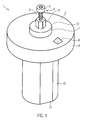
- FIG. 1 shows a device 1 for holding a model of a tooth replacement part.
- the device 1 comprises a disc-shaped element 9 with a flat surface 2. From this flat surface 2 rises a connecting part 7, which is here disc-shaped with a circular cross-section. Both for the disc 9 and independently of the write 7 other cross-sectional shapes are possible as circular, such as square, rectangular, triangular, hexagonal, polygonal or elliptical or other.
- a shape marker in the form of a quadrangular pyramid 8 is shown on the flat surface 2.
- This shape mark 8 allows a unique position identification of the second area.
- the second area here comprises the disc 9 and the disc 7 and the shape mark 8.
- This comprises a rod-shaped element 3 with a hexagonal cross-section.
- other cross-sectional shapes are possible, such as square, rectangular, circular, triangular, pentagonal, octagonal or otherwise polygonal or elliptical.
- the rod-shaped element 3 may be fixedly arranged on the disc 7 and z. B. may have been formed integrally with this. However, it may also have been used in a corresponding receptacle in the disc 7.
- the rod-shaped element 3 has a threaded bore into which a screw 4 can be screwed.
- the screw 4 has a thread 6, with which it is screwed into the threaded hole and a head 5, which represents here, for example, a Allen head.
- the screw 4 corresponds to such a screw with which an abutment can be screwed for example to an implant.
- the first region is given here in this example by the surface 12 of the disc 7, the rod-shaped element 3 and the screw 4.
- the device 1 comprises a holding part 10, which is designed rod-shaped here. This is provided with a flat 11 on one side. By this flattening, the device can be kept in a unique position.
- a unique position identification can already be given only by the holding part 10.
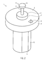
- FIG. 2 shows a variant of the device for holding the model of a tooth replacement part. It differs from the device of Figure 1 only in the part that specifies the inner shape of a dental prosthesis.
- an element 15 with a rod 17 and a head 16 is formed to specify the inner shape. This may either have been inserted into the disc 7 or be integrally formed therewith or otherwise secured to the disc (eg screwed in).
- the variant in Figure 2 is merely exemplary.
- the inner shape of the tooth replacement part does not have to be specified by the holding device, since this can be inserted later digitally when creating a model of digital data.
- the holder already has the inner shape of the tooth replacement part. For example, for the estimation of wall thicknesses in the model this is advantageous.
- the device has a first area in which the model can be modeled. For example, in FIG. 2, if the element 15 is missing with the rod 17 and the head 16, the first area is given by the surface 12 of the disk 7.
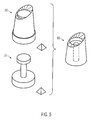
- FIG. 3 shows the holder from FIG. 2 with a modeled dental prosthesis part.
- the model 18 of the dental prosthesis is, for example, made of wax on the surface 12 around the element 15.
- FIG. 4 a shows a variant of the device for holding, in which a notch 20 is provided in the disk 9 on the side, with which a clear position identification of the device for holding is likewise made possible.
- FIG. 4 b shows a further example in which three hemispherical elements 21 are provided on the surface 2 of the disk 9.
- a device for holding with a model of a tooth replacement part 18, as shown in Figure 3 can be scanned with a scanning device.
- Dental scanners for such procedures are known. With such a dental scanner, the outer shape of the model 18, the exposed surface of the head 16 and the surface 12 can be scanned. Thus, the outer shape of the dental prosthesis part can be determined. Furthermore, with the scanner, for example, the surface 2 and the shape mark 8 can be detected. Also, the edges, which are given by the disc 7 and the disc 7 itself can be scanned. A correspondingly obtained data record is shown by way of example in FIG. 5 with the reference numeral 30.
- the data set 31 shown in FIG. 5 reflects the actually desired inner shape of the dental prosthesis part, whereas the shaped parts in FIGS. 1, 2 and 3 are merely an orientation aid for creating the model.
- the data set 31 used to create the digital model does not necessarily have to correspond exactly to the shape given in the device 1 for holding, although this is of course possible.
- the data 30 and 31 in FIG. 5 can be combined with a corresponding (software) method in order subsequently to obtain a digital model 33 of a dental prosthetic item.
- a variety of methods can be used.
- the relative arrangement of the data set 30 and 31 can be determined on the basis of the unique position identification of the holder and subsequently the model 33 can be obtained by "subtracting" the two data sets.
- the model 33 has an abutment in which a central opening for a screw thread and space for the head of a screw is specified.
- Such a digital model 33 may be fed to a known CAM method, such as a milling method, 3D lithography or the like, to produce a dental prosthetic item.
- the invention further relates to a computer-readable medium having instructions for performing one of the methods described herein as soon as the corresponding instructions are loaded onto a computer.
Abstract
Description
Die Erfindung betrifft eine Vorrichtung zum Halten eines Modells eines Zahnersatzteils, eine Vorrichtung zum Scannen von Objekten, ein Verfahren zum Erstellen eines digitalen Modells eines Zahnersatzteils sowie einem dazugehörigen Datenträger und ein Verfahren zum Herstellen eines Zahnersatzteils.The invention relates to a device for holding a model of a tooth replacement part, a device for scanning objects, a method for creating a digital model of a tooth replacement part as well as an associated data carrier and a method for producing a tooth replacement part.
Das Modellieren von Zahnersatzteilen, wie etwa eines Abutments, ist bekannt. Ein Abutment ist ein Teil einer zahnärztlichen Versorgung, das auf ein Implantat z.B. aufgeschraubt wird. Auf das Abutment kann eine Krone oder eine Brücke oder anderes aufgesetzt werden.The modeling of dental prostheses, such as an abutment, is known. An abutment is a part of a dental care that is placed on an implant, e.g. is screwed on. A crown or bridge or other can be placed on the abutment.
In der Regel werden Standard-Abutments verwendet, die einem entsprechendem Implantat angepasst bzw. zugeordnet sind.As a rule, standard abutments are used which are adapted or assigned to a corresponding implant.
Aufgabe der vorliegenden Erfindung ist es, Mittel und Verfahren anzugeben, mit denen eine automatisierte Herstellung von individuellen Abutments oder anderen Zahnersatzteilen ermöglicht wird. Diese Aufgabe wird gelöst mit einer Vorrichtung zum Halten nach Anspruch 1, einer Vorrichtung zum Scannen von Objekten nach Anspruch 10, einem Verfahren zum Erstellen eines digitalen Modells eines Zahnersatzteils nach Anspruch 11, einem Verfahren zum Herstellen eines Zahnersatzteils nach Anspruch 16 und einem computerlesbaren Medium nach Anspruch 17. Bevorzugte Ausführungsformen sind in den Unteransprüchen offenbart.The object of the present invention is to specify means and methods with which an automated production of individual abutments or other tooth replacement parts is made possible. This object is achieved with a device for holding according to claim 1, an apparatus for scanning objects according to
Die Vorrichtung zum Halten eines Modells eines Zahnersatzteils, wie etwa eines Abutments, hat zwei Bereiche. Auf dem ersten Bereich kann das Modell eines Zahnersatzteils aufmodelliert oder ein entsprechendes Modell aufgesetzt werden. Der zweite Bereich erlaubt eine eindeutige Lageidentifizierung der Vorrichtung zum Halten. Der zweite Bereich wird vorzugsweise von dem Modell des Zahnersatzteils nicht abgedeckt, sodass dieser zweite Bereich optisch zugängig bleibt.The device for holding a model of a dental prosthetic item, such as an abutment, has two areas. On the first area, the model of a dental prosthesis can be modeled or a corresponding model can be placed. The second area allows a unique location identification of the device for holding. The second area is preferably not covered by the model of the tooth replacement part, so that this second area remains optically accessible.
Ein solches Modell eines Zahnersatzteils kann beispielsweise aus Wachs modelliert werden, wodurch sich eine leichte, schnelle und individuelle sowie auch wohl bekannte Modellierungsart einsetzen lässt.Such a model of a dental prosthesis part can be modeled, for example, from wax, whereby a light, fast and individual as well as well-known modeling can be used.
Die Vorrichtung zum Halten ist vorzugsweise so dimensioniert, dass sie nur ein Modell eines Zahnersatzteils aufweisen kann, dass einem einzelnen Zahn zugeordnet werden kann, wie etwa ein Abutment, das zu genau einem Implantat (an Stelle eines Zahns) gehört.The device for holding is preferably dimensioned such that it can have only one model of a tooth replacement part that can be associated with a single tooth, such as an abutment that belongs to exactly one implant (instead of one tooth).
Mit dem zweiten Bereich kann die Lage der Vorrichtung zum Halten erkannt werden. Ist die Lage der Vorrichtung zum Halten bekannt, ist damit auch die Lage des ersten Bereichs bekannt. Da das Modell auf dem ersten Bereich aufmodelliert oder aufgesetzt ist, kann durch die Ermittlung der Außenform des Modells und durch die Ermittlung der Lage der Vorrichtung zum Halten und damit der des ersten Bereichs auch die Innenform des Zahnersatzteils definiert werden.With the second area, the position of the device can be detected to hold. If the position of the device for holding known, so that the location of the first area is known. Since the model is modeled or placed on the first area, by determining the outer shape of the model and by determining the position of the device for holding and thus that of the first area, the inner shape of the dental prosthesis can be defined.
Vorteilhaft ist es beispielsweise, wenn der erste Bereich bereits der gewünschten Innenform eines Zahnersatzteils entspricht oder in dem ersten Bereich eine Aufnahme für ein Modellstück ausgebildet ist, wobei dieses Modellstück der Innenform des Zahnersatzteils entsprechen soll. Auf diese Weise ist es bei dem Modellieren des Zahnersatzteils möglich, die später im realen Zahnersatzteil vorkommende Innenform zu berücksichtigen.It is advantageous, for example, if the first region already corresponds to the desired inner shape of a tooth replacement part or in the first region a receptacle for a model piece is formed, this model piece should correspond to the inner shape of the dental prosthesis part. In this way it is possible in the modeling of the dental prosthesis part to take into account the later occurring in the real dental prosthesis part inside shape.
Der zweite Bereich umfasst vorzugsweise zumindest eine, zwei, drei oder mehr ebene Flächen. Derartige ebene Flächen lassen sich vorteilhaft für die Lageidentifizierung der Vorrichtung zum Halten ausnutzen.The second region preferably comprises at least one, two, three or more planar surfaces. Such flat surfaces can be advantageously exploited for the position identification of the device for holding.
Weiterhin kann der zweite Bereich eine, zwei, drei oder mehr Formmarkierungen aufweisen. Formmarkierungen sind solche, die durch die Form gegeben werden. Mögliche Varianten einer Formmarkierung umfassen Nut, Rille, Vertiefung, Erhöhung, Kugel, Halbkugel, eine Kegel- oder eine Pyramidenform, wobei die Formmarkierung jeweils als Positiv- oder Negativform, d. h. als Erhebung als auch als Vertiefung ausgebildet sein kann. Auch mehrere dieser verschiedenen möglichen Formmarkierungen, der gleichen oder verschiedener Art, zusammen sind möglich.Furthermore, the second region may have one, two, three or more shape marks. Mold marks are those given by the mold. Possible variants of a shape marking include groove, groove, depression, elevation, sphere, hemisphere, a conical or a pyramidal shape, wherein the shape marking can be formed in each case as a positive or negative form, ie as a survey as well as a depression. Several of these different possible shape marks, of the same or different kind, together are possible.
Mit derartigen Formmarkierungen, die leicht beispielsweise mit einem optischen oder mechanischen Scanner erkannt werden können, lässt sich sehr präzise die Lage der Vorrichtung zum Halten identifizieren.With such shape marks, which can be easily detected, for example, with an optical or mechanical scanner, the position of the device for holding can be identified very precisely.
Der zweite Bereich umfasst vorzugsweise weiterhin einen Verbindungsteil, der mit dem ersten Bereich verbunden ist. Auch ein solcher Verbindungsteil kann mit einem Scanner in der Regel gut erfasst werden und erlaubt somit Informationsgewinnung für eine Lageidentifizierung der Vorrichtung zum Halten. Dadurch, dass der Verbindungsteil mit dem ersten Teil verbunden ist, ist er auch recht nahe des Modells des Zahnersatzteils, sodass er unter Umständen mit ein- und demselben Scanvorgang, mit dem das Zahnersatzteilmodell abgescannt wird, mit abgescannt werden kann.The second area preferably further comprises a connection part connected to the first area. Also, such a connection part can be detected well with a scanner in the rule and thus allows information acquisition for a location identification of the device for holding. The fact that the connecting part is connected to the first part, he is also quite close to the model of the dental prosthesis part, so that it can be scanned with one and the same scan, with which the dental prosthesis model is scanned, with scanned.
Der Verbindungsteil hat ebenfalls eine vorzugsweise einfache geometrische Form, wie stabförmig oder scheibenförmig, da dies die Lageidentifizierung in bevorzugter Weise ermöglicht. Besonders vorteilhaft ist hierbei, wenn der Verbindungsteil von einer ebenen Fläche absteht. Dies erleichtert die Identifizierung des Verbindungsteils als solches für die Auswertung von Scandaten bei der Lageidentifizierung.The connecting part also has a preferably simple geometric shape, such as rod-shaped or disc-shaped, since this allows the position identification in a preferred manner. It is particularly advantageous if the connecting part protrudes from a flat surface. This facilitates the identification of the connection part as such for the evaluation of scan data in the position identification.
Die Vorrichtung zum Halten hat weiterhin vorzugsweise ein Halteteil mit dem die Vorrichtung in einem Halter gehalten werden kann. Dieser Halteteil ist beispielsweise stabförmig, sodass er in eine entsprechende Hülse eines Halters leicht eingeführt werden kann. (Der Begriff "Halter" wird für diejenige Einrichtung verwendet, die zum Halten der "Vorrichtung zum Halten" vorgesehen ist.)The device for holding further preferably has a holding part with which the device can be held in a holder. This holding part is for example rod-shaped, so that it can be easily inserted into a corresponding sleeve of a holder. (The term "holder" is used for the device intended to hold the "holding device".)
Der Halteteil ist vorzugsweise so ausgebildet, dass eine Halterung der Vorrichtung zum Halten in einer eindeutigen Lage möglich ist. Bei einem zylinderförmigen, stabförmigen Halteteil kann dies beispielsweise durch eine Abflachung des Zylinders an einer oder mehreren Seiten erreicht werden.The holding part is preferably designed so that a holder of the device for holding in a unique position is possible. In the case of a cylindrical, rod-shaped holding part, this can be achieved, for example, by flattening the cylinder on one or more sides.
Eine Vorrichtung zum Scannen von Objekten ist mit einem Halter ausgerüstet, in dem eine oben erwähnte Vorrichtung mit einer eindeutigen Lageorientierung gehalten werden und abgescannt werden kann. Mit einem solchen Scanner können beispielsweise Kiefermodelle und/oder Zahnmodelle und/oder Sägezahnmodellabschnitte oder andere Objekte für eine Dentalversorgung abgescannt werden. Mit ein- und demselben Scanner kann auch ein Modell eines Zahnersatzteils, wie das für ein Abutment, abgescannt werden. Die Vorrichtung weist hierzu einen Halter auf, der eine (zumindest im groben) eindeutige Lageorientierung erlaubt.An apparatus for scanning objects is equipped with a holder, in which an above-mentioned device can be held with a unique positional orientation and scanned. With such a scanner, for example, jaw models and / or tooth models and / or sawtooth model sections or other objects for a Dental care will be scanned. With the same scanner, a model of a dental prosthetic item, such as that for an abutment, can be scanned. For this purpose, the device has a holder which permits a (at least roughly) unambiguous positional orientation.
Bei einem Verfahren zum Erstellen eines digitalen Modells eines Zahnersatzteils, wie etwa eines Abutments, kann zunächst ein Zahnersatzteil an der Vorrichtung zum Halten modelliert oder aufgesetzt werden. Ein solches Zahnersatzteilmodell kann dann zusammen mit der Vorrichtung zum Halten abgescannt werden. Hierzu können Zahnersatzteilmodelle und die Vorrichtung zum Halten mit einem oder mehreren Scanvorgängen gleichzeitig und/oder nacheinander erfasst werden. Die Daten von mehreren Scanvorgängen können mit einem Matchingverfahren zu umfassenderen Datensätzen zusammengesetzt werden. Die Scandaten können dann ausgewertet werden, um zum Einen einen Teil der Form des Zahnersatzteilsmodells und zum Anderen die Lage der Vorrichtung zum Halten zu erfassen.In a method of creating a digital model of a dental prosthetic item, such as an abutment, a dental prosthetic item may first be modeled or attached to the device for retention. Such a dental prosthesis model can then be scanned together with the device for holding. For this purpose, tooth replacement part models and the device for holding with one or more scans can be detected simultaneously and / or successively. The data from multiple scans can be combined with a matching procedure to form more comprehensive datasets. The scan data can then be evaluated in order, on the one hand, to capture a part of the shape of the dental prosthesis part model and, on the other hand, to detect the position of the device for holding.
Die Modellierung des Zahnersatzteils und/oder das Abscannen können an anderen Orten als das Auswerten der Scanndaten erfolgen. Letzteres kann beispielsweise in einem Fertigungszenzrum geschehen, wohingegen das Modellieren und/oder das Abscannen bei einem Dentaltechniker und/oder bei einem Zahnarzt erfolgen kann. Diese Schritte können aber auch alle an einem Ort durchgeführt werden.Modeling of the dental prosthetic item and / or scanning may occur at locations other than evaluating the scan data. The latter can be done, for example, in a manufacturing center, whereas modeling and / or scanning can be performed by a dental technician and / or by a dentist. But these steps can all be done in one place.
Bei dem Verfahren kann vorzugsweise eine Vorrichtung zum Halten, wie sie oben beschrieben worden ist, eingesetzt werden. Auch kann ein solches Verfahren vorzugsweise mit der oben beschriebenen Vorrichtung zum Scannen von Objekten durchgeführt werden.In the method, preferably a holding device as described above can be used. Also, such a method may preferably be performed with the apparatus for scanning objects described above.
Mit einem solchen Verfahren ist es dann beispielsweise möglich, die Innenform des Zahnersatzteils durch die erkannte Lage der Vorrichtung zum Halten festzulegen.With such a method, it is then possible, for example, to determine the inner shape of the dental prosthesis part by the detected position of the device for holding.
Bei einem Verfahren zum Herstellen eines Zahnersatzteils wird zunächst ein digitales Modell, wie oben beschrieben, erstellt und anschließend das Zahnersatzteil unter Zuhilfenahme des digitalen Modells hergestellt. Hierfür sind bekannte CAM-Verfahren, wie Fräsen, 3D-Lithografie oder Ähnliches möglich.In a method for producing a tooth replacement part, a digital model, as described above, is first created, and then the tooth replacement part is produced with the aid of the digital model. For this purpose, known CAM methods, such as milling, 3D lithography or the like are possible.
Ein so hergestelltes Zahnersatzteil kann aus Keramik, Metall, Gold, Metalllegierung, keramischen Legierungen, Kunststoffen oder Ähnlichem bestehen.A dental prosthetic item made in this way may consist of ceramic, metal, gold, metal alloy, ceramic alloys, plastics or the like.
Bevorzugte Ausführungsformen der Erfindung sollen anhand der beigefügten Figuren erläutert werden. Dabei zeigt:
- Figur 1
- eine Vorrichtung zum Halten eines Modells gemäß einem ersten Ausführungsbeispiel der Erfindung;
Figur 2- eine Vorrichtung zum Halten eines Modells gemäß einer zweiten Ausführungsform;
Figur 3- die Vorrichtung aus
Figur 2 mit einem Modell; - Figur 4
- Varianten einer Formmarkierung;
- Figur 5
- schematische Darstellung der Daten zur Erstellung eines digitalen Modells eines Zahnersatzteils.
- FIG. 1
- a device for holding a model according to a first embodiment of the invention;
- FIG. 2
- a device for holding a model according to a second embodiment;
- FIG. 3
- the device of Figure 2 with a model;
- FIG. 4
- Variants of a shape marking;
- FIG. 5
- schematic representation of the data for creating a digital model of a tooth replacement part.
In Figur 1 ist eine Vorrichtung 1 zum Halten eines Modells eines Zahnersatzteils gezeigt. Die Vorrichtung 1 umfasst ein scheibenförmiges Element 9 mit einer ebenen Oberfläche 2. Von dieser ebenen Oberfläche 2 erhebt sich ein Verbindungsteil 7, das hier scheibenförmig mit einem kreisförmigen Querschnitt ausgebildet ist. Sowohl für die Scheibe 9 als auch unabhängig davon für die Schreibe 7 sind andere Querschnittsformen als kreisrund möglich, wie etwa quadratisch, rechteckig, dreieckig, sechseckig, polygonal oder elliptisch oder Anderes.FIG. 1 shows a device 1 for holding a model of a tooth replacement part. The device 1 comprises a disc-shaped
Auf der ebenen Oberfläche 2 ist eine Formmarkierung in Form einer Viereckspyramide 8 dargestellt. Diese Formmarkierung 8 erlaubt eine eindeutige Lageidentifizierung des zweiten Bereichs. Der zweite Bereich umfasst hier die Scheibe 9 und die Scheibe 7 sowie die Formmarkierung 8. Auf der Scheibe 7 ist eine mögliche Innenform eines Abutments angeordnet. Dies umfasst ein stabförmiges Element 3 mit einem hexagonalen Querschnitt. Hier sind auch andere Querschnittsformen möglich, wie etwa quadratisch, rechteckig, kreisrund, dreieckig, fünfeckig, achteckig oder sonst wie polygonal oder elliptisch. Das stabförmige Element 3 kann fest auf der Scheibe 7 angeordnet sein und z. B. einstückig mit diesem ausgebildet worden sein. Es kann jedoch auch in eine entsprechende Aufnahme in der Scheibe 7 eingesetzt worden sein.On the
In dem Beispiel, wie es in Figur 1 gezeigt ist, weist das stabförmige Element 3 eine Gewindebohrung auf, in die eine Schraube 4 eingeschraubt werden kann. Die Schraube 4 hat ein Gewinde 6, mit dem sie in die Gewindebohrung eingeschraubt wird und einen Kopf 5, der hier beispielsweise einen Imbusschraubenkopf darstellt. Die Schraube 4 entspricht einer solchen Schraube, mit der ein Abutment beispielsweise an ein Implantat festgeschraubt werden kann.In the example, as shown in Figure 1, the rod-shaped
Die Darstellung in Figur 1 für das stabförmige Element 3 und die Schraube 4 sind lediglich beispielhaft. Je nach gewünschter Innenform des Zahnersatzteils, so wie beispielsweise eines Abutments, kann hier jede beliebige Form vorhanden sein.The illustration in Figure 1 for the rod-shaped
Der erste Bereich wird hier in diesem Beispiel durch die Oberfläche 12 der Scheibe 7, das stabförmige Element 3 und die Schraube 4 gegeben.The first region is given here in this example by the
Die Vorrichtung 1 umfasst einen Halteteil 10, der hier stabförmig ausgebildet ist. Dieser ist mit einer Abflachung 11 an einer Seite versehen. Durch diese Abflachung lässt sich die Vorrichtung in einer eindeutigen Lage halten.The device 1 comprises a holding
Diese eindeutige Lagerung kann jedoch unter Umständen nicht präzise genug sein, um hieraus auf die Innenform des Modells des Zahnersatzteils schließen zu können. Von daher bietet sich hier eine zusätzliche Erfassung der Lage durch den zweiten Bereich (mit z. B. der Formmarkierung 8) an.However, this unique bearing may not be precise enough to conclude from this on the inner shape of the model of the dental prosthesis. For this reason, an additional detection of the position by the second region (with, for example, the shape marking 8) offers itself here.
In speziellen Beispielen einer Vorrichtung zum Halten eines Modells eines Zahnersatzteils kann jedoch bereits eine eindeutige Lageidentifizierung nur durch den Halteteil 10 gegeben sein.However, in specific examples of a device for holding a model of a tooth replacement part, a unique position identification can already be given only by the holding
Durch jedoch zumindest eine im groben eindeutige Lagerung befindet sich z. B. eine Formmarkierung 8 an einer im groben vorbestimmten Stelle. Nur an dieser im groben vorbestimmten Stelle muss dann mit einem Scanverfahren und der entsprechenden Datenauswertung nach der Formmarkierung gesucht werden, so dass diese dann nicht nur grob, sondern präzise in ihrer Lage bestimmt werden kann.However, by at least one in roughly clear storage is z. B. a
Je mehr Formmarkierungen vorgesehen sind, desto präziser kann die Lage der Vorrichtung zum Halten erfasst werden.The more shape markings are provided, the more precisely the position of the holding device can be detected.
In Figur 2 ist eine Variante der Vorrichtung zum Halten des Modells eines Zahnersatzteils dargestellt. Sie unterscheidet sich von der Vorrichtung aus Figur 1 lediglich in dem Teil, der die Innenform eines Zahnersatzteils vorgibt. Hier ist zur Vorgabe der Innenform ein Element 15 mit einem Stab 17 und einem Kopf 16 ausgebildet. Dieser kann entweder in die Scheibe 7 eingesteckt worden sein oder einstückig mit dieser ausgebildet worden sein oder sonst wie mit der Scheibe befestigt worden sein (z. B. eingeschraubt). Auch die Variante in Figur 2 ist lediglich beispielhaft.FIG. 2 shows a variant of the device for holding the model of a tooth replacement part. It differs from the device of Figure 1 only in the part that specifies the inner shape of a dental prosthesis. Here, an
Es sei hier angemerkt, dass an sich durch die Vorrichtung zum Halten die Innenform des Zahnersatzteils nicht vorgegeben werden muss, da dies später bei der Erstellung eines Modells von digitalen Daten digital eingefügt werden kann. Um jedoch dem Modellierer eine bessere Übersicht über die spätere Struktur des Zahnersatzteils zu geben, ist es vorteilhaft, wenn der Halter bereits die Innenform des Zahnersatzteils aufweist. Beispielsweise für die Abschätzung von Wandstärken in dem Modell ist dies vorteilhaft.It should be noted here that the inner shape of the tooth replacement part does not have to be specified by the holding device, since this can be inserted later digitally when creating a model of digital data. However, in order to give the modeler a better overview of the subsequent structure of the tooth replacement part, it is advantageous if the holder already has the inner shape of the tooth replacement part. For example, for the estimation of wall thicknesses in the model this is advantageous.
Andererseits reicht es auch, wenn die Vorrichtung zum Halten die Innenform nur in etwa vorgibt. So können Abweichungen in einigen Bemaßungen von 5 % oder 10 % vorgesehen sein, beispielsweise um einen Kanal für das Gewinde 6 der Schraube 4 breiter zu machen als das Gewinde 6 selber.On the other hand, it is sufficient if the device for holding the inner mold only approximately pretends. Thus, deviations in some dimensions of 5% or 10% may be provided, for example, to make a channel for the thread 6 of the screw 4 wider than the thread 6 itself.
Unabhängig davon jedoch, ob die Vorrichtung die Innenform des Zahnersatzteils vorgibt oder nicht, weist die Vorrichtung einen ersten Bereich auf, in dem das Modell aufmodelliert werden kann. Fehlt beispielsweise in Figur 2 das Element 15 mit dem Stab 17 und dem Kopf 16, so ist der erste Bereich durch die Oberfläche 12 der Scheibe 7 gegeben.Regardless of whether the device dictates the interior shape of the dental prosthesis or not, the device has a first area in which the model can be modeled. For example, in FIG. 2, if the
In Figur 3 ist der Halter aus Figur 2 mit einem aufmodellierten Zahnersatzteil dargestellt. Das Modell 18 des Zahnersatzteils wird beispielsweise aus Wachs auf der Oberfläche 12 um das Element 15 herummodelliert.FIG. 3 shows the holder from FIG. 2 with a modeled dental prosthesis part. The
In Figur 4 a ist eine Variante der Vorrichtung zum Halten gezeigt, bei der in der Scheibe 9 an der Seite eine Kerbe 20 vorgesehen ist, mit der ebenfalls eine eindeutige Lageidentifizierung der Vorrichtung zum Halten ermöglicht wird.FIG. 4 a shows a variant of the device for holding, in which a
In Figur 4 b ist ein weiters Beispiel gezeigt, bei der drei Halbkugelelemente 21 auf der Oberfläche 2 der Scheibe 9 vorgesehen sind.FIG. 4 b shows a further example in which three
Eine Vorrichtung zum Halten mit einem Modell eines Zahnersatzteils 18, wie es in Figur 3 dargestellt ist, kann mit einer Scanvorrichtung abgescannt werden.A device for holding with a model of a
Dentalscanner für derartige Vorgänge sind bekannt. Mit einem solchen Dentalscanner können die Außenform des Modells 18, die freiliegende Oberfläche des Kopfes 16 und der Oberfläche 12 abgescannt werden. Damit kann die Außenform des Zahnersatzteils bestimmt werden. Weiterhin können mit dem Scanner beispielsweise die Oberfläche 2 und die Formmarkierung 8 erfasst werden. Auch die Kanten, die durch die Scheibe 7 gegeben werden bzw. die Scheibe 7 selbst können abgescannt werden. Ein entsprechend gewonnener Datensatz ist beispielhaft in Figur 5 mit der Bezugsziffer 30 dargestellt.Dental scanners for such procedures are known. With such a dental scanner, the outer shape of the
Bei einem Verfahren zum Erstellen eines digitalen Modells eines Zahnersatzteils ist weiterhin ein Datensatz vorhanden, der die gewünschte Innenform eines Zahnersatzteils wiedergibt. Ein entsprechender Datensatz ist in Figur 5 unter Bezugsziffer 31 dargestellt. Die Relation dieses Datensatzes zu einer Formmarkierung ist bekannt und ebenfalls gespeichert (siehe Figur 5).In a method for creating a digital model of a dental prosthesis part, there is also a dataset which reproduces the desired inner shape of a tooth replacement part. A corresponding data record is shown in FIG. 5 under
Der in Figur 5 dargestellte Datensatz 31 gibt die tatsächlich gewünschte Innenform des Zahnersatzteils wieder, wohingegen die Formstücke in den Figuren 1, 2 und 3 lediglich eine Orientierungshilfe für das Erstellen des Modells sind. So kann der Datensatz 31, der im Wesentlichen der Form der Vorrichtung zum Halten aus Figur 2 entspricht, in seinem Durchmesser etwas größer sein, um so beispielsweise etwas Spiel für das Einsetzen einer Schraube oder Ähnliches zu ermöglichen.The
Hier ist also festzuhalten, dass der Datensatz 31, der zur Erstellung des digitalen Modells verwendet wird, nicht zwangsläufig der Form, die in der Vorrichtung 1 zum Halten vorgegeben ist, exakt entsprechen muss, auch wenn dies natürlich möglich ist.It should be noted here that the data set 31 used to create the digital model does not necessarily have to correspond exactly to the shape given in the device 1 for holding, although this is of course possible.
Die Daten 30 und 31 in Figur 5 können mit einem entsprechenden (Software-) Verfahren zusammengesetzt werden, um anschließend ein digitales Modell 33 eines Zahnersatzteils zu gewinnen. Hierzu können verschiedenste Verfahren eingesetzt werden. Beispielsweise kann die relative Anordnung des Datensatzes 30 und 31 anhand der eindeutigen Lageidentifizierung des Halters bestimmt werden und anschließend durch "Subtraktion" der beiden Datensätze das Modell 33 gewonnen werden. Das Modell 33 weist ein Abutment auf, in dem eine zentrale Öffnung für ein Schraubengewinde sowie Raum für den Kopf einer Schraube vorgegeben ist. Ein solches digitales Modell 33 kann einem bekannten CAM-Verfahren, wie etwa einem Fräsverfahren, 3D-Lithographie oder Ähnlichem zugeführt werden, um ein Zahnersatzteil herzustellen.The
Die Erfindung betrifft weiterhin einen computerlesbaren Datenträger, mit Instruktionen zum Durchführen eines der hier beschriebenen Verfahren, sobald die entsprechenden Instruktionen auf einen Computer geladen werden.The invention further relates to a computer-readable medium having instructions for performing one of the methods described herein as soon as the corresponding instructions are loaded onto a computer.
Claims (17)
einem Halter, in den eine Vorrichtung nach einem der Ansprüche 1 bis 9 mit einer eindeutigen Lageorientierung gehalten und abgescannt werden kann.Device for scanning objects, such as jaw models and / or tooth models and / or sawtooth model sections, with
a holder, in which a device according to one of claims 1 to 9 can be held and scanned with a unique positional orientation.
Priority Applications (1)
| Application Number | Priority Date | Filing Date | Title |
|---|---|---|---|
| EP10151569.0A EP2181665B1 (en) | 2006-11-07 | 2007-11-05 | Method of producing a dental restoration |
Applications Claiming Priority (1)
| Application Number | Priority Date | Filing Date | Title |
|---|---|---|---|
| DE102006052420A DE102006052420A1 (en) | 2006-11-07 | 2006-11-07 | Device for holding a model |
Related Child Applications (2)
| Application Number | Title | Priority Date | Filing Date |
|---|---|---|---|
| EP10151569.0A Division-Into EP2181665B1 (en) | 2006-11-07 | 2007-11-05 | Method of producing a dental restoration |
| EP10151569.0A Division EP2181665B1 (en) | 2006-11-07 | 2007-11-05 | Method of producing a dental restoration |
Publications (3)
| Publication Number | Publication Date |
|---|---|
| EP1920731A2 true EP1920731A2 (en) | 2008-05-14 |
| EP1920731A3 EP1920731A3 (en) | 2008-10-15 |
| EP1920731B1 EP1920731B1 (en) | 2016-07-20 |
Family
ID=39125113
Family Applications (2)
| Application Number | Title | Priority Date | Filing Date |
|---|---|---|---|
| EP07021489.5A Active EP1920731B1 (en) | 2006-11-07 | 2007-11-05 | Device for holding a model |
| EP10151569.0A Active EP2181665B1 (en) | 2006-11-07 | 2007-11-05 | Method of producing a dental restoration |
Family Applications After (1)
| Application Number | Title | Priority Date | Filing Date |
|---|---|---|---|
| EP10151569.0A Active EP2181665B1 (en) | 2006-11-07 | 2007-11-05 | Method of producing a dental restoration |
Country Status (7)
| Country | Link |
|---|---|
| US (2) | US20080108014A1 (en) |
| EP (2) | EP1920731B1 (en) |
| JP (1) | JP4833951B2 (en) |
| AU (2) | AU2007231764B2 (en) |
| CA (1) | CA2609855A1 (en) |
| DE (1) | DE102006052420A1 (en) |
| ES (1) | ES2585655T3 (en) |
Cited By (2)
| Publication number | Priority date | Publication date | Assignee | Title |
|---|---|---|---|---|
| WO2009049778A2 (en) * | 2007-10-09 | 2009-04-23 | Straumann Holding Ag | Device for holding a model support of an abutment model |
| CN109341567A (en) * | 2018-08-31 | 2019-02-15 | 先临三维科技股份有限公司 | Scan sub-mount, stamp fixture, stamp fixture assembly and its artificial tooth spatial digitizer |
Families Citing this family (12)
| Publication number | Priority date | Publication date | Assignee | Title |
|---|---|---|---|---|
| DE202011001654U1 (en) * | 2011-01-18 | 2012-04-19 | Straumann Holding Ag | Device for aligning a dental arch model and device for detecting surfaces |
| US9610145B2 (en) * | 2013-03-15 | 2017-04-04 | Cmp Industries Llc | Precision-milled denture teeth and method and devices for making same |
| EP2974690B1 (en) | 2013-03-11 | 2019-01-09 | Fujitsu Limited | Program for design of dental prostheses, device for design of dental prostheses, and method for design of dental prostheses |
| ITMI20131561A1 (en) * | 2013-09-23 | 2015-03-24 | Dental Knowledge S R L | METHOD OF REALIZING A DENTAL PROSTHESIS |
| US10016262B2 (en) | 2014-06-16 | 2018-07-10 | Align Technology, Inc. | Unitary dental model |
| KR101505529B1 (en) * | 2014-06-21 | 2015-03-25 | 주식회사 디오에프연구소 | A table for 3D scanning tooth structure model |
| EP2965712B1 (en) * | 2014-07-07 | 2019-01-30 | Kulzer GmbH | Improved device for supporting preformed elements for producing single superstructures for dental prostheses and system for supporting this device on the processing machine of said preformed elements |
| EP3130310A1 (en) * | 2015-08-11 | 2017-02-15 | Rheinisch-Westfälische Technische Hochschule Aachen | Scanning aid and method of scanning an object |
| KR101602749B1 (en) * | 2015-09-03 | 2016-03-11 | 주식회사 메디트 | Apparatus and Method for Measuring Teeth Shape |
| LU100319B1 (en) * | 2017-06-20 | 2018-12-20 | Laboratoire Dentaire Hornbeck Jacques S A R L | Mounting element for production of a dental prosthesis, a prosthesis and method of manufacturing same |
| US10959817B2 (en) * | 2019-08-14 | 2021-03-30 | Sdc U.S. Smilepay Spv | Dental model holding system |
| KR102429383B1 (en) * | 2020-05-12 | 2022-08-04 | 오스템임플란트 주식회사 | Device and method for providing scan data |
Citations (11)
| Publication number | Priority date | Publication date | Assignee | Title |
|---|---|---|---|---|
| US6224371B1 (en) * | 1998-12-29 | 2001-05-01 | Silvio De Luca | Supporting device for the manufacture of dental prosthetic components |
| US20010029010A1 (en) * | 2000-04-07 | 2001-10-11 | Renishaw Plc | Mount and mount transit system |
| US20010034010A1 (en) * | 2000-01-05 | 2001-10-25 | Macdougald Joseph A. | Method and apparatus for preparing dental restorations |
| US20030123943A1 (en) * | 2000-05-29 | 2003-07-03 | Hiroaki Hamada | Measuring/machining system for dentistry |
| US6640150B1 (en) * | 1998-05-29 | 2003-10-28 | Nobel Biocare Ab | Method for producing a dental first attachment part for an implant or a second attachment part, and a holder for a model of the first attachment part |
| US20040032594A1 (en) * | 2000-11-08 | 2004-02-19 | Gerhard Weber | Surface mapping and generating devices and methods for surface mapping and surface generation |
| US6766217B1 (en) * | 1999-08-02 | 2004-07-20 | Kabushiki Kaisya Advance | Method of manufacturing dental prosthesis, method of placing object for measurement and measuring device |
| US20050254064A1 (en) * | 2002-07-22 | 2005-11-17 | Sirona Dental Systems Gmbh | Measuring device for a model and machining device equipped with the same |
| US20060093204A1 (en) * | 2004-10-20 | 2006-05-04 | Willytec Gmbh | Method and apparatus for producing datasets for making dental protheses |
| US20060115784A1 (en) * | 2002-01-22 | 2006-06-01 | Renishaw Plc | Re-orientatable sample holder |
| US20060127858A1 (en) * | 2004-12-14 | 2006-06-15 | Huafeng Wen | Producing accurate base for a dental arch model |
Family Cites Families (13)
| Publication number | Priority date | Publication date | Assignee | Title |
|---|---|---|---|---|
| CH665551A5 (en) * | 1984-03-06 | 1988-05-31 | Werner Hans Dr Med De Moermann | BLANK FOR THE MANUFACTURE OF DENTAL TECHNOLOGY MOLDED PARTS. |
| SE501410C2 (en) * | 1993-07-12 | 1995-02-06 | Nobelpharma Ab | Method and apparatus in connection with the manufacture of tooth, bridge, etc. |
| DE10102115B4 (en) * | 2001-01-18 | 2006-12-28 | Hint-Els Gmbh | Holder for a fixed object on a receiving plate |
| DE10133568A1 (en) * | 2001-07-13 | 2003-01-30 | Degussa Dental Gmbh & Co Kg | Method and device for three-dimensional measurement and digitization of a body |
| DE10394004D2 (en) * | 2002-10-18 | 2005-09-08 | Willytec Gmbh | Facilities and methods for the production of dental prostheses |
| GB0327698D0 (en) * | 2003-11-28 | 2003-12-31 | Renishaw Plc | Method and apparatus for scanning |
| JP4451274B2 (en) * | 2004-10-28 | 2010-04-14 | 株式会社ジーシー | Measuring object wearing tool and method for producing three-dimensional shape data of dental prosthesis using the same |
| JP4451275B2 (en) * | 2004-10-29 | 2010-04-14 | 株式会社ジーシー | Method for creating three-dimensional shape data of dental prosthesis |
| DE102004054880B3 (en) * | 2004-11-12 | 2006-05-18 | Sirona Dental Systems Gmbh | Holder for holding a toothed model for the production of rotational receptacles and holding device therefor |
| DE102004054876B3 (en) * | 2004-11-12 | 2006-07-27 | Sirona Dental Systems Gmbh | Measuring device for 3D measurement of tooth models, sliding plate and method |
| DE202005003439U1 (en) * | 2005-03-03 | 2005-07-28 | Thiel, Franz-Rudolf | Workpiece fixing and repositioning device for use on dentistry machine, has three spherical bodies aligned together in between device parts that are subjected to magnetic resilience created through fixture device |
| DE102005033738B4 (en) * | 2005-07-15 | 2008-06-05 | Sirona Dental Systems Gmbh | Method and device for producing dental prostheses |
| CA2556533A1 (en) * | 2005-08-24 | 2007-02-24 | Degudent Gmbh | Method of determining the shape of a dental technology object and apparatus performing the method |
-
2006
- 2006-11-07 DE DE102006052420A patent/DE102006052420A1/en not_active Withdrawn
-
2007
- 2007-11-05 EP EP07021489.5A patent/EP1920731B1/en active Active
- 2007-11-05 EP EP10151569.0A patent/EP2181665B1/en active Active
- 2007-11-05 ES ES07021489.5T patent/ES2585655T3/en active Active
- 2007-11-06 CA CA002609855A patent/CA2609855A1/en not_active Abandoned
- 2007-11-07 JP JP2007290124A patent/JP4833951B2/en not_active Expired - Fee Related
- 2007-11-07 AU AU2007231764A patent/AU2007231764B2/en not_active Ceased
- 2007-11-07 US US11/936,192 patent/US20080108014A1/en not_active Abandoned
-
2010
- 2010-12-08 AU AU2010249235A patent/AU2010249235C1/en not_active Ceased
-
2011
- 2011-09-21 US US13/238,589 patent/US20120009541A1/en not_active Abandoned
Patent Citations (11)
| Publication number | Priority date | Publication date | Assignee | Title |
|---|---|---|---|---|
| US6640150B1 (en) * | 1998-05-29 | 2003-10-28 | Nobel Biocare Ab | Method for producing a dental first attachment part for an implant or a second attachment part, and a holder for a model of the first attachment part |
| US6224371B1 (en) * | 1998-12-29 | 2001-05-01 | Silvio De Luca | Supporting device for the manufacture of dental prosthetic components |
| US6766217B1 (en) * | 1999-08-02 | 2004-07-20 | Kabushiki Kaisya Advance | Method of manufacturing dental prosthesis, method of placing object for measurement and measuring device |
| US20010034010A1 (en) * | 2000-01-05 | 2001-10-25 | Macdougald Joseph A. | Method and apparatus for preparing dental restorations |
| US20010029010A1 (en) * | 2000-04-07 | 2001-10-11 | Renishaw Plc | Mount and mount transit system |
| US20030123943A1 (en) * | 2000-05-29 | 2003-07-03 | Hiroaki Hamada | Measuring/machining system for dentistry |
| US20040032594A1 (en) * | 2000-11-08 | 2004-02-19 | Gerhard Weber | Surface mapping and generating devices and methods for surface mapping and surface generation |
| US20060115784A1 (en) * | 2002-01-22 | 2006-06-01 | Renishaw Plc | Re-orientatable sample holder |
| US20050254064A1 (en) * | 2002-07-22 | 2005-11-17 | Sirona Dental Systems Gmbh | Measuring device for a model and machining device equipped with the same |
| US20060093204A1 (en) * | 2004-10-20 | 2006-05-04 | Willytec Gmbh | Method and apparatus for producing datasets for making dental protheses |
| US20060127858A1 (en) * | 2004-12-14 | 2006-06-15 | Huafeng Wen | Producing accurate base for a dental arch model |
Cited By (4)
| Publication number | Priority date | Publication date | Assignee | Title |
|---|---|---|---|---|
| WO2009049778A2 (en) * | 2007-10-09 | 2009-04-23 | Straumann Holding Ag | Device for holding a model support of an abutment model |
| WO2009049778A3 (en) * | 2007-10-09 | 2009-08-06 | Straumann Holding Ag | Device for holding a model support of an abutment model |
| US8448928B2 (en) | 2007-10-09 | 2013-05-28 | Straumann Holding Ag | Device for holding a model support of an abutment model |
| CN109341567A (en) * | 2018-08-31 | 2019-02-15 | 先临三维科技股份有限公司 | Scan sub-mount, stamp fixture, stamp fixture assembly and its artificial tooth spatial digitizer |
Also Published As
| Publication number | Publication date |
|---|---|
| AU2010249235C1 (en) | 2013-05-23 |
| ES2585655T3 (en) | 2016-10-07 |
| US20120009541A1 (en) | 2012-01-12 |
| EP1920731B1 (en) | 2016-07-20 |
| AU2010249235A1 (en) | 2011-01-06 |
| JP2008114079A (en) | 2008-05-22 |
| AU2007231764B2 (en) | 2010-09-30 |
| EP2181665A1 (en) | 2010-05-05 |
| CA2609855A1 (en) | 2008-05-07 |
| AU2010249235B2 (en) | 2013-01-10 |
| DE102006052420A1 (en) | 2008-05-08 |
| AU2007231764A1 (en) | 2008-05-22 |
| EP1920731A3 (en) | 2008-10-15 |
| EP2181665B1 (en) | 2014-04-23 |
| US20080108014A1 (en) | 2008-05-08 |
| JP4833951B2 (en) | 2011-12-07 |
Similar Documents
| Publication | Publication Date | Title |
|---|---|---|
| EP2181665B1 (en) | Method of producing a dental restoration | |
| EP2237740B1 (en) | Method for modeling an individual dental prosthesis | |
| DE10233314B4 (en) | Measuring device for an original and thus provided processing machine | |
| EP2111180B1 (en) | Method concerning the modelling and the production of an artificial denture or its base | |
| EP1920730A2 (en) | Method for determining the position and orientation of a dental implant | |
| DE102011003561A1 (en) | Impression, drilling template and method for providing a positional relationship and for creating a surgical template | |
| DE102014102770B4 (en) | Bite fork and method and system for displaying a bit | |
| WO2011147988A2 (en) | Dental tool | |
| DE102009014013B4 (en) | Detection auxiliary body and its use for detecting the position and orientation of an implant | |
| EP3471655B1 (en) | Scan body | |
| DE102008028214A1 (en) | Scan build system | |
| WO2018015562A1 (en) | Measuring system and method for measuring an implant-implant situation | |
| EP1913895A2 (en) | Method for manufacturing the head part of a dental implant and production set for such a method | |
| EP2594227A2 (en) | Impression device and method for three-dimensional detection of intra-oral structures, and a corresponding scanning device | |
| DE102011014664A1 (en) | Device for fixing, positioning, scanning and creating denture partial model i.e. abutment, has holding element attached at element via retaining element, which directly or indirectly fixes denture partial model in height and/or position | |
| DE102004051165B3 (en) | Method and device for generating data sets for the production of dental prostheses | |
| EP2197388A2 (en) | Device for holding a model support of an abutment model | |
| EP2957251A1 (en) | Device for use in a method for the production of a dental implant structure | |
| EP1820469A1 (en) | Device for scanning a tooth model | |
| DE102014102923A1 (en) | Insertion post, system and method for detecting the position of an implanted implant | |
| AT523132A2 (en) | SCAN BODY WITH LONG ARM | |
| EP2964134A1 (en) | Adapter sleeve for insertion into dental models | |
| DE102016122204B4 (en) | Laboratory analog system | |
| AT523131A2 (en) | SCAN BODIES WITH ORIENTATION MARKINGS | |
| WO2021089156A1 (en) | Dental model comprising a detachable tooth stump |
Legal Events
| Date | Code | Title | Description |
|---|---|---|---|
| PUAI | Public reference made under article 153(3) epc to a published international application that has entered the european phase |
Free format text: ORIGINAL CODE: 0009012 |
|
| AK | Designated contracting states |
Kind code of ref document: A2 Designated state(s): AT BE BG CH CY CZ DE DK EE ES FI FR GB GR HU IE IS IT LI LT LU LV MC MT NL PL PT RO SE SI SK TR |
|
| AX | Request for extension of the european patent |
Extension state: AL BA HR MK RS |
|
| PUAL | Search report despatched |
Free format text: ORIGINAL CODE: 0009013 |
|
| AK | Designated contracting states |
Kind code of ref document: A3 Designated state(s): AT BE BG CH CY CZ DE DK EE ES FI FR GB GR HU IE IS IT LI LT LU LV MC MT NL PL PT RO SE SI SK TR |
|
| AX | Request for extension of the european patent |
Extension state: AL BA HR MK RS |
|
| 17P | Request for examination filed |
Effective date: 20090414 |
|
| 17Q | First examination report despatched |
Effective date: 20090519 |
|
| AKX | Designation fees paid |
Designated state(s): AT BE BG CH CY CZ DE DK EE ES FI FR GB GR HU IE IS IT LI LT LU LV MC MT NL PL PT RO SE SI SK TR |
|
| RAP1 | Party data changed (applicant data changed or rights of an application transferred) |
Owner name: INSTITUT STRAUMANN AG |
|
| RIC1 | Information provided on ipc code assigned before grant |
Ipc: A61C 9/00 20060101ALI20151210BHEP Ipc: A61C 13/00 20060101AFI20151210BHEP Ipc: A61C 13/12 20060101ALI20151210BHEP |
|
| GRAP | Despatch of communication of intention to grant a patent |
Free format text: ORIGINAL CODE: EPIDOSNIGR1 |
|
| INTG | Intention to grant announced |
Effective date: 20160127 |
|
| GRAS | Grant fee paid |
Free format text: ORIGINAL CODE: EPIDOSNIGR3 |
|
| GRAA | (expected) grant |
Free format text: ORIGINAL CODE: 0009210 |
|
| AK | Designated contracting states |
Kind code of ref document: B1 Designated state(s): AT BE BG CH CY CZ DE DK EE ES FI FR GB GR HU IE IS IT LI LT LU LV MC MT NL PL PT RO SE SI SK TR |
|
| REG | Reference to a national code |
Ref country code: GB Ref legal event code: FG4D Free format text: NOT ENGLISH |
|
| REG | Reference to a national code |
Ref country code: CH Ref legal event code: EP |
|
| REG | Reference to a national code |
Ref country code: IE Ref legal event code: FG4D Free format text: LANGUAGE OF EP DOCUMENT: GERMAN |
|
| REG | Reference to a national code |
Ref country code: AT Ref legal event code: REF Ref document number: 813383 Country of ref document: AT Kind code of ref document: T Effective date: 20160815 |
|
| REG | Reference to a national code |
Ref country code: DE Ref legal event code: R096 Ref document number: 502007014949 Country of ref document: DE |
|
| REG | Reference to a national code |
Ref country code: CH Ref legal event code: NV Representative=s name: PATENTANWAELTE SCHAAD, BALASS, MENZL AND PARTN, CH |
|
| REG | Reference to a national code |
Ref country code: ES Ref legal event code: FG2A Ref document number: 2585655 Country of ref document: ES Kind code of ref document: T3 Effective date: 20161007 |
|
| REG | Reference to a national code |
Ref country code: LT Ref legal event code: MG4D |
|
| REG | Reference to a national code |
Ref country code: NL Ref legal event code: MP Effective date: 20160720 |
|
| PG25 | Lapsed in a contracting state [announced via postgrant information from national office to epo] |
Ref country code: LT Free format text: LAPSE BECAUSE OF FAILURE TO SUBMIT A TRANSLATION OF THE DESCRIPTION OR TO PAY THE FEE WITHIN THE PRESCRIBED TIME-LIMIT Effective date: 20160720 Ref country code: FI Free format text: LAPSE BECAUSE OF FAILURE TO SUBMIT A TRANSLATION OF THE DESCRIPTION OR TO PAY THE FEE WITHIN THE PRESCRIBED TIME-LIMIT Effective date: 20160720 Ref country code: NL Free format text: LAPSE BECAUSE OF FAILURE TO SUBMIT A TRANSLATION OF THE DESCRIPTION OR TO PAY THE FEE WITHIN THE PRESCRIBED TIME-LIMIT Effective date: 20160720 Ref country code: IS Free format text: LAPSE BECAUSE OF FAILURE TO SUBMIT A TRANSLATION OF THE DESCRIPTION OR TO PAY THE FEE WITHIN THE PRESCRIBED TIME-LIMIT Effective date: 20161120 |
|
| PG25 | Lapsed in a contracting state [announced via postgrant information from national office to epo] |
Ref country code: LV Free format text: LAPSE BECAUSE OF FAILURE TO SUBMIT A TRANSLATION OF THE DESCRIPTION OR TO PAY THE FEE WITHIN THE PRESCRIBED TIME-LIMIT Effective date: 20160720 Ref country code: PT Free format text: LAPSE BECAUSE OF FAILURE TO SUBMIT A TRANSLATION OF THE DESCRIPTION OR TO PAY THE FEE WITHIN THE PRESCRIBED TIME-LIMIT Effective date: 20161121 Ref country code: GR Free format text: LAPSE BECAUSE OF FAILURE TO SUBMIT A TRANSLATION OF THE DESCRIPTION OR TO PAY THE FEE WITHIN THE PRESCRIBED TIME-LIMIT Effective date: 20161021 Ref country code: PL Free format text: LAPSE BECAUSE OF FAILURE TO SUBMIT A TRANSLATION OF THE DESCRIPTION OR TO PAY THE FEE WITHIN THE PRESCRIBED TIME-LIMIT Effective date: 20160720 Ref country code: SE Free format text: LAPSE BECAUSE OF FAILURE TO SUBMIT A TRANSLATION OF THE DESCRIPTION OR TO PAY THE FEE WITHIN THE PRESCRIBED TIME-LIMIT Effective date: 20160720 Ref country code: BE Free format text: LAPSE BECAUSE OF NON-PAYMENT OF DUE FEES Effective date: 20161130 |
|
| REG | Reference to a national code |
Ref country code: DE Ref legal event code: R097 Ref document number: 502007014949 Country of ref document: DE |
|
| PG25 | Lapsed in a contracting state [announced via postgrant information from national office to epo] |
Ref country code: RO Free format text: LAPSE BECAUSE OF FAILURE TO SUBMIT A TRANSLATION OF THE DESCRIPTION OR TO PAY THE FEE WITHIN THE PRESCRIBED TIME-LIMIT Effective date: 20160720 Ref country code: EE Free format text: LAPSE BECAUSE OF FAILURE TO SUBMIT A TRANSLATION OF THE DESCRIPTION OR TO PAY THE FEE WITHIN THE PRESCRIBED TIME-LIMIT Effective date: 20160720 |
|
| PLBE | No opposition filed within time limit |
Free format text: ORIGINAL CODE: 0009261 |
|
| STAA | Information on the status of an ep patent application or granted ep patent |
Free format text: STATUS: NO OPPOSITION FILED WITHIN TIME LIMIT |
|
| PG25 | Lapsed in a contracting state [announced via postgrant information from national office to epo] |
Ref country code: CZ Free format text: LAPSE BECAUSE OF FAILURE TO SUBMIT A TRANSLATION OF THE DESCRIPTION OR TO PAY THE FEE WITHIN THE PRESCRIBED TIME-LIMIT Effective date: 20160720 Ref country code: DK Free format text: LAPSE BECAUSE OF FAILURE TO SUBMIT A TRANSLATION OF THE DESCRIPTION OR TO PAY THE FEE WITHIN THE PRESCRIBED TIME-LIMIT Effective date: 20160720 Ref country code: SK Free format text: LAPSE BECAUSE OF FAILURE TO SUBMIT A TRANSLATION OF THE DESCRIPTION OR TO PAY THE FEE WITHIN THE PRESCRIBED TIME-LIMIT Effective date: 20160720 Ref country code: BG Free format text: LAPSE BECAUSE OF FAILURE TO SUBMIT A TRANSLATION OF THE DESCRIPTION OR TO PAY THE FEE WITHIN THE PRESCRIBED TIME-LIMIT Effective date: 20161020 |
|
| 26N | No opposition filed |
Effective date: 20170421 |
|
| REG | Reference to a national code |
Ref country code: IE Ref legal event code: MM4A |
|
| REG | Reference to a national code |
Ref country code: FR Ref legal event code: ST Effective date: 20170731 |
|
| PG25 | Lapsed in a contracting state [announced via postgrant information from national office to epo] |
Ref country code: SI Free format text: LAPSE BECAUSE OF FAILURE TO SUBMIT A TRANSLATION OF THE DESCRIPTION OR TO PAY THE FEE WITHIN THE PRESCRIBED TIME-LIMIT Effective date: 20160720 |
|
| PG25 | Lapsed in a contracting state [announced via postgrant information from national office to epo] |
Ref country code: LU Free format text: LAPSE BECAUSE OF NON-PAYMENT OF DUE FEES Effective date: 20161130 |
|
| PG25 | Lapsed in a contracting state [announced via postgrant information from national office to epo] |
Ref country code: FR Free format text: LAPSE BECAUSE OF NON-PAYMENT OF DUE FEES Effective date: 20161130 |
|
| PG25 | Lapsed in a contracting state [announced via postgrant information from national office to epo] |
Ref country code: IE Free format text: LAPSE BECAUSE OF NON-PAYMENT OF DUE FEES Effective date: 20161105 |
|
| REG | Reference to a national code |
Ref country code: AT Ref legal event code: MM01 Ref document number: 813383 Country of ref document: AT Kind code of ref document: T Effective date: 20161105 |
|
| PG25 | Lapsed in a contracting state [announced via postgrant information from national office to epo] |
Ref country code: AT Free format text: LAPSE BECAUSE OF NON-PAYMENT OF DUE FEES Effective date: 20161105 |
|
| REG | Reference to a national code |
Ref country code: BE Ref legal event code: MM Effective date: 20161130 |
|
| PG25 | Lapsed in a contracting state [announced via postgrant information from national office to epo] |
Ref country code: CY Free format text: LAPSE BECAUSE OF FAILURE TO SUBMIT A TRANSLATION OF THE DESCRIPTION OR TO PAY THE FEE WITHIN THE PRESCRIBED TIME-LIMIT Effective date: 20160720 Ref country code: HU Free format text: LAPSE BECAUSE OF FAILURE TO SUBMIT A TRANSLATION OF THE DESCRIPTION OR TO PAY THE FEE WITHIN THE PRESCRIBED TIME-LIMIT; INVALID AB INITIO Effective date: 20071105 |
|
| PG25 | Lapsed in a contracting state [announced via postgrant information from national office to epo] |
Ref country code: MC Free format text: LAPSE BECAUSE OF FAILURE TO SUBMIT A TRANSLATION OF THE DESCRIPTION OR TO PAY THE FEE WITHIN THE PRESCRIBED TIME-LIMIT Effective date: 20160720 Ref country code: TR Free format text: LAPSE BECAUSE OF FAILURE TO SUBMIT A TRANSLATION OF THE DESCRIPTION OR TO PAY THE FEE WITHIN THE PRESCRIBED TIME-LIMIT Effective date: 20160720 |
|
| PG25 | Lapsed in a contracting state [announced via postgrant information from national office to epo] |
Ref country code: MT Free format text: LAPSE BECAUSE OF FAILURE TO SUBMIT A TRANSLATION OF THE DESCRIPTION OR TO PAY THE FEE WITHIN THE PRESCRIBED TIME-LIMIT Effective date: 20160720 |
|
| PGFP | Annual fee paid to national office [announced via postgrant information from national office to epo] |
Ref country code: IT Payment date: 20191128 Year of fee payment: 13 |
|
| PG25 | Lapsed in a contracting state [announced via postgrant information from national office to epo] |
Ref country code: IT Free format text: LAPSE BECAUSE OF NON-PAYMENT OF DUE FEES Effective date: 20201105 |
|
| PGFP | Annual fee paid to national office [announced via postgrant information from national office to epo] |
Ref country code: ES Payment date: 20230125 Year of fee payment: 16 |
|
| PGFP | Annual fee paid to national office [announced via postgrant information from national office to epo] |
Ref country code: GB Payment date: 20231123 Year of fee payment: 17 |
|
| PGFP | Annual fee paid to national office [announced via postgrant information from national office to epo] |
Ref country code: DE Payment date: 20231121 Year of fee payment: 17 Ref country code: CH Payment date: 20231201 Year of fee payment: 17 |
|
| PGFP | Annual fee paid to national office [announced via postgrant information from national office to epo] |
Ref country code: ES Payment date: 20240124 Year of fee payment: 17 |