EP1908537B1 - Verfahren und System zur Produktion von dreidimensionalen Produkten aus Draht - Google Patents
Verfahren und System zur Produktion von dreidimensionalen Produkten aus Draht Download PDFInfo
- Publication number
- EP1908537B1 EP1908537B1 EP07117186A EP07117186A EP1908537B1 EP 1908537 B1 EP1908537 B1 EP 1908537B1 EP 07117186 A EP07117186 A EP 07117186A EP 07117186 A EP07117186 A EP 07117186A EP 1908537 B1 EP1908537 B1 EP 1908537B1
- Authority
- EP
- European Patent Office
- Prior art keywords
- wire
- production
- dimensional products
- bending
- rebar
- Prior art date
- Legal status (The legal status is an assumption and is not a legal conclusion. Google has not performed a legal analysis and makes no representation as to the accuracy of the status listed.)
- Active
Links
- 238000004519 manufacturing process Methods 0.000 title claims abstract description 38
- 238000000034 method Methods 0.000 title claims abstract description 37
- 230000008569 process Effects 0.000 title claims abstract description 35
- 239000000463 material Substances 0.000 claims abstract description 75
- 230000007246 mechanism Effects 0.000 claims abstract description 47
- 238000005452 bending Methods 0.000 claims abstract description 46
- 230000000694 effects Effects 0.000 description 3
- 230000015572 biosynthetic process Effects 0.000 description 1
- 230000008859 change Effects 0.000 description 1
- 238000010276 construction Methods 0.000 description 1
- 238000005259 measurement Methods 0.000 description 1
- 238000001228 spectrum Methods 0.000 description 1
Images

Classifications
-
- B—PERFORMING OPERATIONS; TRANSPORTING
- B21—MECHANICAL METAL-WORKING WITHOUT ESSENTIALLY REMOVING MATERIAL; PUNCHING METAL
- B21D—WORKING OR PROCESSING OF SHEET METAL OR METAL TUBES, RODS OR PROFILES WITHOUT ESSENTIALLY REMOVING MATERIAL; PUNCHING METAL
- B21D11/00—Bending not restricted to forms of material mentioned in only one of groups B21D5/00, B21D7/00, B21D9/00; Bending not provided for in groups B21D5/00 - B21D9/00; Twisting
- B21D11/10—Bending specially adapted to produce specific articles, e.g. leaf springs
- B21D11/12—Bending specially adapted to produce specific articles, e.g. leaf springs the articles being reinforcements for concrete
-
- B—PERFORMING OPERATIONS; TRANSPORTING
- B21—MECHANICAL METAL-WORKING WITHOUT ESSENTIALLY REMOVING MATERIAL; PUNCHING METAL
- B21F—WORKING OR PROCESSING OF METAL WIRE
- B21F1/00—Bending wire other than coiling; Straightening wire
-
- B—PERFORMING OPERATIONS; TRANSPORTING
- B21—MECHANICAL METAL-WORKING WITHOUT ESSENTIALLY REMOVING MATERIAL; PUNCHING METAL
- B21F—WORKING OR PROCESSING OF METAL WIRE
- B21F1/00—Bending wire other than coiling; Straightening wire
- B21F1/006—Bending wire other than coiling; Straightening wire in 3D with means to rotate the tools about the wire axis
Definitions
- the invention relates to a process of production of three-dimensional products from wire, rods, rebar, or other suitable material of any cross-section, capable of undergoing plastic deformation, and to a system which implements this process.
- the three-dimensional products may find use in a broad field of applications and cover a very large spectrum of shapes.
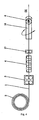
- US 5170654 A (ANAGNOSTOPOULOS) 15.12.1992 disclosed an automatic bending machine wherein wire is advanced to a straightening mechanism 2 and passes through a measuring mechanism 3.
- a bending mechanism 6 bends the wire in a plane, and a cutter 7 is used for cutting the formed product from the wire.
- a fixed gripper 8 and a rotating gripper 9 comprise a mechanism that is found between the straightener 4 and the bending mechanism 6, this mechanism functioning to hold the material with fixed gripper 8 and simultaneously rotate the material about its longitudinal axis X with the rotating gripper 9. This is explained at columns 3-5 of US5170654 . This system permits the production of some three-dimensional products from wire.
- a great disadvantage in each of the above-described state-of-the-art processes and in machines of the these first and second types is that each one of them respectively provides only one respective way for generating the third dimension in a shape.
- This entails great limitations primarily as to productivity, taking into consideration that the in-question products in almost all cases must be produced in very large numbers.
- whichever process is employed has the consequence of significant delay in production. That is because with the first process and automatic machines of the first type (a), the delay will occur during the generation of the large sides; while in the second process and automatic machines of the second type (b) the delay will occur during the generation of the small sides of the product space as the entire bending mechanism is rotated.
- the invention provides for the first time the breakthrough coexistence, within one system, of arrangement 14 and bending mechanism 12 with the individual characteristics referred to above, thus providing the heretofore unenvisioned and unknown capability of selectively choosing and energizing within the same shape one or the other of the mechanisms 12, 14 according to the geometry and the dimensions of the different portions of the at-production shape. This uniquely imparts the flexibility to improve times of production of the various or different three-dimensional shapes produced.
- the present invention provides the following among its specific advantages. Taking into consideration that these three-dimensional products are usually produced in very large number:
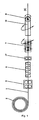
- FIG. 1 depicts in idealization the process of production and its kinematic requirements, according to the present invention.
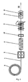
- FIG. 2 schematically depicts one of the systems that implement the process of production of three-dimensional products according to the present invention.
- FIG. 3 depicts in idealization a process of production of the three-dimensional products according to the state of the art.
- FIG. 4 depicts in idealization a second process of production of the three-dimensional products according to the state of the art.
- the process may be understood to comprise several steps.
- the wire 1, rod, rebar, or other suitable material 1 able to undergo plastic deformation, originating from spool 2 is advanced 3, is straightened 4, there occurs a measurement 17 of its length of the advanced material, and afterwards the material 1 passes sequentially from two arrangements 7, 10 of which the first 7 can hold the material 1 and rotate it around the longitudinal axis X, while the second 10 can rotate around the longitudinal axis X of the material 1, having the capability to bend the material 1 at a desired and predetermined angle and to cut it 6.
- this process it is possible to effectively choose from these two ways of creating the third dimension in the entire product or in a portion thereof, the more suitable and faster, each time.
- one can significantly reduce the time of production of the product, independent of its shape, its dimensions and its other geometric characteristics.
- a process for production of three-dimensional products from wire 1, rod, rebar, or other suitable material of any cross-section, originating from a spool 2, and capable of undergoing plastic deformation may comprise advancement 3 of material 1, measuring 17 of the advanced length, and straightening 4. Bending is effected with a bending means 5, that has the ability to rotate around the longitudinal axis X of the wire 1 and to bend the material 1 plastically, at-will, at selected and predetermined angles in different planes that may be different amongst themselves within the same shape.
- a final cutting 6 may occur upon completion of the three-dimensional product.
- the process is characterized in that according to the form and individual geometric characteristics and the dimensions of the for-production three-dimensional product it is possible to generate bendings in different planes.
- the bending means 5 for generating a different-plane bending or a second suitable means 7 with which is held fixed the wire 1 at one location and gripped at another location so as to be twisted around its longitudinal axis X, securing thus the most suitable and fastest manner of generation of individual portions of the product so as to improve the time for its production.
- a process according to the immediately preceding paragraph may be further characterized in that the location of twisting of material 1 is located after the location at which the material is held fixed.
- a process according to either of the two preceding paragraphs may be further characterized in that the twisting of material 1 around its longitudinal axis X may be made with right directional twist and left directional twist.
- the process may be implemented in an innovative system 8 which comprises an advancement mechanism 3,9 of wire 1 originating from spool 2. Also included are a straightening mechanism 11, 4 that straightens the material 1; an arrangement 18, 17 for measuring length of the material advanced; an arrangement 14, 7 able to hold the material with suitable stationary grippers 15 and simultaneously with other rotating grippers 16, which grip the material, to twist it at desired angle around its longitudinal axis X; a bending mechanism 12 that may bend the material plastically in one plane and simultaneously may rotate at a suitable angle around the longitudinal axis X of the material 1, capable thus to generate at-will selected and predetermined bendings on different planes, which bendings may be different amongst themselves within the same shape; and a cutting arrangement 13, 6 that may be carried by the bending mechanism.
- a system 8 for the production of three-dimensional products from wire 1 or rod, rebar, or other suitable material of any cross-section capable of undergoing plastic deformation may comprise an advancement mechanism 9 suitable for advancing the material originating from spool 2, a suitable straightening mechanism 11 that straightens the advancing material 1, and a length measuring arrangement 18 towards which advances the material.
- a bending mechanism 12 that can bend the material plastically on one plane and also is able to rotate to a desired angle around the longitudinal axis X of the wire 1, capable thus of generating at-will selected and predetermined bendings in different planes, which may be different amongst themselves within the same shape and which bending mechanism 12 may carry a cutting arrangement 13 for the material.
- the system 8 is characterized in that between the straightening mechanism 11 and the bending mechanism 12, that bends the material in the plane and also in the space, is interposed a gripper arrangement 14, able to hold the material with suitable stationary grippers 15 and simultaneously with other grippers 16 to twist it to a desired angle around the longitudinal axis X deforming it plastically at a desired location, so that the bends that have been made by the bending mechanism 12 may change plane.
- Either the bending mechanism 12 rotation, or the arrangement 14 may be energized at choice according to the geometric characteristics of the for-production shape, producing thus three-dimensional products from wire 1 or other suitable material capable of undergoing plastic deformation, with the suitable and best choice of advancement, bending and torsion and with the best speed corresponding with the dimensions and the requirements of the shape, each time.
- a system 8 according to the immediately preceding paragraph may be further characterized in that the arrangement 14 that is able to hold steady the material with suitable fixed grippers 15 and simultaneously with other rotating grippers 16 to twist it to a desired angle around its longitudinal axis X to deform it plastically at a desired location, is located between the straightening mechanism 11 and the bending mechanism 12.
- a system 8 according to any one of the two immediately preceding paragraphs may be further characterized in that the arrangement 14 holds steady the material with suitable grippers 15 and simultaneously with other grippers 16 may twist it to a desired angle around its longitudinal axis X with either right directional twist and left directional twist.
- a system 8 according to any one of the three immediately preceding paragraphs may be further characterized in that the supervision, the coordination and the control of all the functions of the process of production of the three-dimensional product are made by a suitable electronic computer, in which are entered the necessary characteristics of the for-production three-dimensional product.
- the individual elements and mechanisms that comprise the system 8 according to the present invention may be arranged in series, so that the arrangement 14 is located between the straightening mechanism 11 and the bending mechanism 12.
- the layout 8 according to the present invention may work wire 1, rods or other suitable material of any cross section, able to undergo plastic deformation.
- the present invention is not limited in any manner to the example described and in-the-drawing-portrayed implementation. Furthermore, in the implementation of the invention, the materials that are used as well as the dimensions of the individual elements can be in accordance with the requirements of the particular construction.
Claims (9)
- System (8) zum Erzeugen von dreidimensionalen Erzeugnissen aus Draht (1), Stäben, Bewehrungsstahl oder anderem Material mit jeglichem Querschnitt, das dazu imstande ist, sich einer plastischen Verformung zu unterziehen, umfassend:einen Vorschubmechanismus (9, 3) zum Vorrücken des Materials (1);einen Richtmechanismus (11, 4) zum Geraderichten des vorrückenden Materials (1);eine Längenmessanordnung (18, 17) zum Messen der Länge des vorgerückten Materials (1);einen Biegemechanismus (12, 10) zum Biegen des Materials (1) in einer Ebene, wobei der Biegemechanismus (12, 10) zu einem gewünschten Winkel um eine Längsachse (X) des Materials (1) zum Erzeugen ausgewählter vorgegebener Biegungen des Materials (1) in verschiedenen Ebenen selektiv drehbar ist;und dadurch gekennzeichnet, dass:eine Greiferanordnung (14, 7) zwischen dem Richtmechanismus (11, 4) und dem Biegemechanismus (12, 10) zwischengeschaltet ist;die Greiferanordnung (14, 7) ortsfeste Greifer (15) enthält;die Greiferanordnung (14, 7) Drehgreifer (16) zum selektiven Verwinden von Material (1) um seine Längsachse (X) enthält.
- System (8) zum Erzeugen von dreidimensionalen Erzeugnissen aus Draht (1), Stäben, Bewehrungsstahl oder anderem Material mit jeglichem Querschnitt, das dazu imstande ist, sich einer plastischen Verformung zu unterziehen, nach Anspruch 1, ferner gekennzeichnet durch:eine Schneidanordnung (13, 6), die von dem Biegemechanismus (12, 10) getragen ist.
- System (8) zum Erzeugen von dreidimensionalen Erzeugnissen aus Draht (1), Stäben, Bewehrungsstahl oder anderem Material mit jeglichem Querschnitt, das dazu imstande ist, sich einer plastischen Verformung zu unterziehen, nach einem der Ansprüche 1 oder 2, ferner gekennzeichnet durch:die Drehgreifer (16), die zum Verwinden des Materials (1) um seine Längsachse (X) mit rechtsgerichteter Verwindung und linksgerichteter Verwindung gestaltet sind.
- System (8) zum Erzeugen von dreidimensionalen Erzeugnissen aus Draht (1), Stäben, Bewehrungsstahl oder anderem Material mit jeglichem Querschnitt, das dazu imstande ist, sich einer plastischen Verformung zu unterziehen, nach einem der Ansprüche 1, 2 oder 3, ferner gekennzeichnet durch:einen geeigneten elektronischen Rechner zur Überwachung, Koordination und Steuerung der Erzeugung der dreidimensionalen Erzeugnisse.
- Verfahren zum Erzeugen von dreidimensionalen Erzeugnissen aus Draht (1), Stäben, Bewehrungsstahl oder anderem geeigneten Material mit jeglichem Querschnitt, das dazu imstande ist, sich einer plastischen Verformung zu unterziehen, folgende Schritte umfassend:Vorrücken (3) des Materials (1);Messen (17) der vorgerückten Länge des Materials (1);Geraderichten (4) des Materials (1);Biegen (10) des Materials (1) mit einem Biegemittel (10, 12), das zum Drehen um die Längsachse (X) des Materials (1) und zum beliebigen plastischen Biegen des Materials (1) an ausgewählten vorgegebenen Winkeln in verschiedenen Ebenen gestaltet ist;Schneiden (6) des Materials (1) nach Fertigstellung des dreidimensionalen Erzeugnisses;und gekennzeichnet durch den Schritt des:Auswählens von entweder dem Biegemittel (10, 12) oder einem zweiten Mittel (7), das das Material (1) starr an einer Stelle hält und es gleichzeitig durch Greifen desselben an einer zweiten Stelle um seine Längsachse (X) verwindet, zum Erzeugen von Biegungen in verschiedenen Ebenen.
- Verfahren zum Erzeugen von dreidimensionalen Erzeugnissen aus Draht (1), Stäben, Bewehrungsstahl oder anderem geeigneten Material mit jeglichem Querschnitt, das dazu imstande ist, sich einer plastischen Verformung zu unterziehen, nach Anspruch 5, ferner gekennzeichnet durch den Schritt des:Verwindens des Materials (1) um seine Längsachse (X) mit dem zweiten Mittel (7) in einer rechtsgerichteten Verwindung oder einer linksgerichteten Verwindung.
- Verfahren zum Erzeugen von dreidimensionalen Erzeugnissen aus Draht (1), Stäben, Bewehrungsstahl oder anderem geeigneten Material mit jeglichem Querschnitt, das dazu imstande ist, sich einer plastischen Verformung zu unterziehen, nach einem der Ansprüche 5 oder 6, ferner gekennzeichnet durch den Schritt des:örtlichen Festlegens der zweiten Stelle nach der ersten Stelle.
- Verfahren zum Erzeugen von dreidimensionalen Erzeugnissen aus Draht (1), Stäben, Bewehrungsstahl oder anderem geeigneten Material mit jeglichem Querschnitt, das dazu imstande ist, sich einer plastischen Verformung zu unterziehen, nach einem der Ansprüche 5, 6 oder 7, ferner dadurch gekennzeichnet, dass:das Auswählen von entweder dem Biegemittel (10, 12) oder einem zweiten Mittel (7) gemäß den großen Erzeugnisseiten oder den kleinen Erzeugnisseiten des dreidimensionalen Vorproduktionserzeugnisses erfolgt.
- Verfahren zum Erzeugen von dreidimensionalen Erzeugnissen aus Draht (1), Stäben, Bewehrungsstahl oder anderem geeigneten Material mit jeglichem Querschnitt, das dazu imstande ist, sich einer plastischen Verformung zu unterziehen, nach einem der Ansprüche 5, 6, 7 oder 8, ferner dadurch gekennzeichnet, dass:das Auswählen von entweder dem Biegemittel (10, 12) oder einem zweiten Mittel (7) zum Sicherstellen der geeignetsten und schnellsten Art und Weise der Erzeugung individueller Abschnitte des Erzeugnisses erfolgt.
Applications Claiming Priority (1)
| Application Number | Priority Date | Filing Date | Title |
|---|---|---|---|
| GR20060100545A GR1005986B (el) | 2006-10-03 | 2006-10-03 | Μεθοδος και συστημα παραγωγης τρισδιαστατων προϊοντων απο συρμα. |
Publications (2)
| Publication Number | Publication Date |
|---|---|
| EP1908537A1 EP1908537A1 (de) | 2008-04-09 |
| EP1908537B1 true EP1908537B1 (de) | 2011-01-05 |
Family
ID=38669852
Family Applications (1)
| Application Number | Title | Priority Date | Filing Date |
|---|---|---|---|
| EP07117186A Active EP1908537B1 (de) | 2006-10-03 | 2007-09-25 | Verfahren und System zur Produktion von dreidimensionalen Produkten aus Draht |
Country Status (7)
| Country | Link |
|---|---|
| US (1) | US7878038B2 (de) |
| EP (1) | EP1908537B1 (de) |
| AT (1) | ATE494084T1 (de) |
| DE (1) | DE602007011704D1 (de) |
| DK (1) | DK1908537T3 (de) |
| ES (1) | ES2358449T3 (de) |
| GR (1) | GR1005986B (de) |
Families Citing this family (23)
| Publication number | Priority date | Publication date | Assignee | Title |
|---|---|---|---|---|
| US8549888B2 (en) | 2008-04-04 | 2013-10-08 | Nuvasive, Inc. | System and device for designing and forming a surgical implant |
| CN102317000B (zh) * | 2010-04-07 | 2014-09-03 | 株式会社太洋 | 全自动型管折弯机 |
| CN101961763B (zh) * | 2010-10-28 | 2012-12-05 | 建科机械(天津)股份有限公司 | 钢筋三维成型机的扭线装置 |
| IT1403849B1 (it) * | 2011-02-04 | 2013-11-08 | Galluccio | Metodo e apparecchiatura per realizzare armature per cemento armato |
| ITUD20110116A1 (it) | 2011-07-20 | 2013-01-21 | Piegatrici Macch Elettr | Macchina per la piegatura di barre metalliche e relativo procedimento |
| US20140033782A1 (en) * | 2012-01-24 | 2014-02-06 | Fci Holdings Delaware, Inc. | Method and Apparatus for Continuous Bulbing of Stranded Cable |
| US9156077B2 (en) * | 2012-03-29 | 2015-10-13 | L&P Property Management Company | Method of making border wire |
| CN103212653B (zh) * | 2013-03-26 | 2014-11-26 | 苏州盟川自动化科技有限公司 | 一种熔丝的自动送丝及切断折弯装置 |
| GR1008523B (el) | 2014-04-01 | 2015-07-09 | Αντωνιος Παναγιωτη Αναγνωστοπουλος | Μεθοδος και συστημα τροφοδοσιας διαμηκων συρματων ή μπετοβεργων σε μηχανηματα παραγωγης πλεγματος |
| US20170014725A1 (en) * | 2015-07-15 | 2017-01-19 | Ignacio Marc Asperas | Method Of Manufacturing A Light Weight Ball Configured To Adhere & Maintain Snow For A Snowman |
| CN106694747A (zh) * | 2015-07-27 | 2017-05-24 | 青岛欧勃亚商用设备有限公司 | 三维铁线成型一体机及方法 |
| CN105537457A (zh) * | 2016-02-03 | 2016-05-04 | 建科机械(天津)股份有限公司 | 一种钢筋弯箍机的伸缩装置 |
| CN106938307A (zh) * | 2017-03-29 | 2017-07-11 | 国网山东省电力公司菏泽供电公司 | 一种智能截线机 |
| DE102017217032A1 (de) * | 2017-09-26 | 2019-03-28 | Wafios Aktiengesellschaft | Verfahren und Biegemaschine zur Herstellung von Biegeteilen aus Flachmaterial |
| DE102018215501A1 (de) * | 2018-09-12 | 2020-03-12 | Wafios Aktiengesellschaft | Verfahren zur Herstellung eines Biegeteils und Biegemaschine zur Durchführung des Verfahrens |
| CN109365698B (zh) * | 2018-09-13 | 2020-06-09 | 葛骏驰 | 一种全自动单根钢丝卷毛机及其加工方法 |
| CN109531771B (zh) * | 2018-12-07 | 2020-03-24 | 中国建筑材料科学研究总院有限公司 | 基于3d打印制备建筑结构的设备及方法 |
| CN110560602A (zh) * | 2019-09-30 | 2019-12-13 | 汪海军 | 一种折线机机床 |
| CN110523881B (zh) * | 2019-09-30 | 2021-06-22 | 邵东智能制造技术研究院有限公司 | 钢筋上料弯折装置 |
| CN111215566B (zh) * | 2019-11-29 | 2021-06-15 | 高晖 | 一种建筑机械用钢筋拉直系统 |
| CN111730007B (zh) * | 2020-08-07 | 2022-06-24 | 山东睿煜矿用材料加工有限公司 | 一种钢筋弯箍机的矫直装置 |
| CN113636771B (zh) * | 2021-09-06 | 2023-04-28 | 浙江理工大学 | 弧形状钢纤维、制造模具及方法及应用该钢纤维的混凝土 |
| CN113754332A (zh) * | 2021-09-06 | 2021-12-07 | 浙江理工大学 | 三维钢纤维、制造模具及方法及应用三维钢纤维的混凝土 |
Family Cites Families (12)
| Publication number | Priority date | Publication date | Assignee | Title |
|---|---|---|---|---|
| US813215A (en) * | 1904-04-29 | 1906-02-20 | Charles A Juengst | Stapling-machine. |
| US3922901A (en) * | 1973-11-29 | 1975-12-02 | Weldun Tool & Engineering Co | Apparatus for bending tubing |
| DE3415006A1 (de) * | 1984-04-19 | 1985-11-07 | Helge Dr. 8000 München Fischer-Brandies | Zahntechnisches verfahren und vorrichtung zum biegen und tordieren eines drahtstueckes |
| EP0231092B1 (de) * | 1986-01-29 | 1991-08-21 | Ronald Edward Benton | Biegemaschine |
| GR890100232A (el) * | 1989-04-11 | 1991-09-27 | Panagiotis Anagnostopoulos | Επιπρόσ?ετος κουρμπαδόρος συρματουργικών μηχανών δια κατασκευήν σχημάτων τριών διαστάσεων. |
| GR1001322B (el) * | 1990-04-06 | 1993-08-31 | Panagiotis Anagnostopoulos | Μηχανισμος μηχανων καμψης συρματος σε τρεις διαστασεις. |
| DE4229294C1 (de) * | 1992-09-02 | 1993-12-16 | Wafios Maschinen Wagner | Vorrichtung zum Formen von Draht |
| DE19816403C2 (de) * | 1998-04-11 | 2001-06-13 | Wafios Maschinen Wagner | Vorrichtung zum Formen von Draht mit einer Drahtbremseinrichtung und Verfahren zum Formen von Draht |
| FR2806943B1 (fr) * | 2000-04-03 | 2002-08-16 | Macsoft | Machine de cintrage de barres a nez de pliage effacable |
| US6644079B2 (en) * | 2001-12-21 | 2003-11-11 | Burr Oak Tool And Gauge Company, Inc. | Hairpin bender with leg length measurement and adjustment feature |
| GR1004318B (el) * | 2002-06-05 | 2003-08-28 | Αντωνης Παναγιωτη Αναγνωστοπουλος | Μεθοδος και μηχανη ταυτοχρονης και παραλληλης παραγωγης ιδιων προιοντων με ευθυγραμμιση και καμψη απο υλικο συρμα, μπετοβεργα σωληνα η αλλο υλικο πρισματικης διατομης |
| US7240528B2 (en) * | 2004-11-22 | 2007-07-10 | Lingualcare, Inc. | Method and device for shaping an orthodontic archwire |
-
2006
- 2006-10-03 GR GR20060100545A patent/GR1005986B/el active IP Right Grant
-
2007
- 2007-09-25 DE DE602007011704T patent/DE602007011704D1/de active Active
- 2007-09-25 ES ES07117186T patent/ES2358449T3/es active Active
- 2007-09-25 DK DK07117186.2T patent/DK1908537T3/da active
- 2007-09-25 EP EP07117186A patent/EP1908537B1/de active Active
- 2007-09-25 US US11/861,277 patent/US7878038B2/en not_active Expired - Fee Related
- 2007-09-25 AT AT07117186T patent/ATE494084T1/de active
Also Published As
| Publication number | Publication date |
|---|---|
| GR20060100545A (el) | 2008-05-21 |
| US7878038B2 (en) | 2011-02-01 |
| EP1908537A1 (de) | 2008-04-09 |
| DE602007011704D1 (de) | 2011-02-17 |
| US20080078226A1 (en) | 2008-04-03 |
| DK1908537T3 (da) | 2011-04-04 |
| ES2358449T3 (es) | 2011-05-10 |
| ATE494084T1 (de) | 2011-01-15 |
| GR1005986B (el) | 2008-07-10 |
Similar Documents
| Publication | Publication Date | Title |
|---|---|---|
| EP1908537B1 (de) | Verfahren und System zur Produktion von dreidimensionalen Produkten aus Draht | |
| US9370817B2 (en) | Method and system for programming the control of a multiaxis forming machine and forming machine | |
| EP2822714B1 (de) | Verfahren und system zum biegen von abstandshaltern | |
| EP1852195A2 (de) | Verfahren und Maschine zur Herstellung von dreidimensionalen Bügeln | |
| KR100908981B1 (ko) | 밴딩 기능이 부착된 파이프 성형기 | |
| KR102189749B1 (ko) | 금속 와이어를 드로잉 및 교정하는 장치, 및 해당 드로잉 및 교정 방법 | |
| US7497105B2 (en) | Machine and method for parallel production of similar products, through straightening and bending of wires, wire rods, metal tubes or other material of prismatic cross section | |
| RU2766591C2 (ru) | Станок и способ гибки удлиненных металлических изделий таких, как прутки, стержни, профильные прутки или прочие подобные изделия | |
| EP0209876A2 (de) | Universalbiegemaschine und entsprechendes Biegeverfahren | |
| EP2714296B1 (de) | Vorrichtung zur herstellung von bügeln | |
| US20050103080A1 (en) | Method and machine for simultaneous and parallel production of similar products, through straightening and bending of wires, wire rods, metal tubes or other material of prismatic cross section | |
| RU2678852C2 (ru) | Гибочное устройство для продолговатых металлических изделий, таких как полосы, прутки или металлическая проволока, и соответствующий способ изгибания | |
| JP6571994B2 (ja) | コイルばね製造装置と、コイルばねの製造方法 | |
| WO2013011373A1 (en) | Machine for bending metal bars and corresponding method | |
| EP1478476B1 (de) | Verfahren und mechanismus zum zuführen von drähten, stäben, rohren oder sonstigen materialien mit prismatischem querschnitt von verschiedenen zuführlinien zu einer behandlungslinie | |
| JP2001321868A (ja) | ロッド材曲成物の成形加工方法と、それに用いる成形加工装置 | |
| JPS5976635A (ja) | 二重コイルねじりばねの製法及びその製造装置 | |
| JP2020506805A (ja) | 金網を製造するための装置及び方法 | |
| WO2003082492A1 (en) | Method and machine for bending of wire rods, wires, tubes or other material of prismatic cross section | |
| WO2023275840A1 (en) | Method of bending and bending machine for the execution of a method of bending | |
| JPH10314849A (ja) | 長尺ワークの曲げ・捩り加工装置 | |
| JP2002146786A (ja) | 丸鋼スパイラルの製造方法 | |
| PL113914B1 (en) | Spring making apparatus especially for making double volute springs |
Legal Events
| Date | Code | Title | Description |
|---|---|---|---|
| PUAI | Public reference made under article 153(3) epc to a published international application that has entered the european phase |
Free format text: ORIGINAL CODE: 0009012 |
|
| AK | Designated contracting states |
Kind code of ref document: A1 Designated state(s): AT BE BG CH CY CZ DE DK EE ES FI FR GB GR HU IE IS IT LI LT LU LV MC MT NL PL PT RO SE SI SK TR |
|
| AX | Request for extension of the european patent |
Extension state: AL BA HR MK RS |
|
| 17P | Request for examination filed |
Effective date: 20080328 |
|
| 17Q | First examination report despatched |
Effective date: 20080528 |
|
| AKX | Designation fees paid |
Designated state(s): AT BE BG CH CY CZ DE DK EE ES FI FR GB GR HU IE IS IT LI LT LU LV MC MT NL PL PT RO SE SI SK TR |
|
| RAP1 | Party data changed (applicant data changed or rights of an application transferred) |
Owner name: ANAGNOSTOPOULOS, ANTONIOS |
|
| RIN1 | Information on inventor provided before grant (corrected) |
Inventor name: ANAGNOSTOPOULOS, ANTONIOS |
|
| GRAP | Despatch of communication of intention to grant a patent |
Free format text: ORIGINAL CODE: EPIDOSNIGR1 |
|
| GRAS | Grant fee paid |
Free format text: ORIGINAL CODE: EPIDOSNIGR3 |
|
| GRAA | (expected) grant |
Free format text: ORIGINAL CODE: 0009210 |
|
| AK | Designated contracting states |
Kind code of ref document: B1 Designated state(s): AT BE BG CH CY CZ DE DK EE ES FI FR GB GR HU IE IS IT LI LT LU LV MC MT NL PL PT RO SE SI SK TR |
|
| REG | Reference to a national code |
Ref country code: GB Ref legal event code: FG4D |
|
| REG | Reference to a national code |
Ref country code: CH Ref legal event code: EP |
|
| REG | Reference to a national code |
Ref country code: IE Ref legal event code: FG4D |
|
| REF | Corresponds to: |
Ref document number: 602007011704 Country of ref document: DE Date of ref document: 20110217 Kind code of ref document: P |
|
| REG | Reference to a national code |
Ref country code: DE Ref legal event code: R096 Ref document number: 602007011704 Country of ref document: DE Effective date: 20110217 |
|
| REG | Reference to a national code |
Ref country code: CH Ref legal event code: NV Representative=s name: ROSENICH PAUL; GISLER CHRISTIAN PATENTBUERO PAUL R |
|
| REG | Reference to a national code |
Ref country code: DK Ref legal event code: T3 |
|
| REG | Reference to a national code |
Ref country code: SE Ref legal event code: TRGR |
|
| REG | Reference to a national code |
Ref country code: NL Ref legal event code: T3 |
|
| REG | Reference to a national code |
Ref country code: ES Ref legal event code: FG2A Ref document number: 2358449 Country of ref document: ES Kind code of ref document: T3 Effective date: 20110427 |
|
| PG25 | Lapsed in a contracting state [announced via postgrant information from national office to epo] |
Ref country code: SI Free format text: LAPSE BECAUSE OF FAILURE TO SUBMIT A TRANSLATION OF THE DESCRIPTION OR TO PAY THE FEE WITHIN THE PRESCRIBED TIME-LIMIT Effective date: 20110105 |
|
| LTIE | Lt: invalidation of european patent or patent extension |
Effective date: 20110105 |
|
| PG25 | Lapsed in a contracting state [announced via postgrant information from national office to epo] |
Ref country code: LT Free format text: LAPSE BECAUSE OF FAILURE TO SUBMIT A TRANSLATION OF THE DESCRIPTION OR TO PAY THE FEE WITHIN THE PRESCRIBED TIME-LIMIT Effective date: 20110105 Ref country code: PT Free format text: LAPSE BECAUSE OF FAILURE TO SUBMIT A TRANSLATION OF THE DESCRIPTION OR TO PAY THE FEE WITHIN THE PRESCRIBED TIME-LIMIT Effective date: 20110505 Ref country code: LV Free format text: LAPSE BECAUSE OF FAILURE TO SUBMIT A TRANSLATION OF THE DESCRIPTION OR TO PAY THE FEE WITHIN THE PRESCRIBED TIME-LIMIT Effective date: 20110105 Ref country code: IS Free format text: LAPSE BECAUSE OF FAILURE TO SUBMIT A TRANSLATION OF THE DESCRIPTION OR TO PAY THE FEE WITHIN THE PRESCRIBED TIME-LIMIT Effective date: 20110505 Ref country code: GR Free format text: LAPSE BECAUSE OF FAILURE TO SUBMIT A TRANSLATION OF THE DESCRIPTION OR TO PAY THE FEE WITHIN THE PRESCRIBED TIME-LIMIT Effective date: 20110406 |
|
| PG25 | Lapsed in a contracting state [announced via postgrant information from national office to epo] |
Ref country code: BE Free format text: LAPSE BECAUSE OF FAILURE TO SUBMIT A TRANSLATION OF THE DESCRIPTION OR TO PAY THE FEE WITHIN THE PRESCRIBED TIME-LIMIT Effective date: 20110105 Ref country code: CY Free format text: LAPSE BECAUSE OF FAILURE TO SUBMIT A TRANSLATION OF THE DESCRIPTION OR TO PAY THE FEE WITHIN THE PRESCRIBED TIME-LIMIT Effective date: 20110105 Ref country code: FI Free format text: LAPSE BECAUSE OF FAILURE TO SUBMIT A TRANSLATION OF THE DESCRIPTION OR TO PAY THE FEE WITHIN THE PRESCRIBED TIME-LIMIT Effective date: 20110105 Ref country code: BG Free format text: LAPSE BECAUSE OF FAILURE TO SUBMIT A TRANSLATION OF THE DESCRIPTION OR TO PAY THE FEE WITHIN THE PRESCRIBED TIME-LIMIT Effective date: 20110405 Ref country code: PL Free format text: LAPSE BECAUSE OF FAILURE TO SUBMIT A TRANSLATION OF THE DESCRIPTION OR TO PAY THE FEE WITHIN THE PRESCRIBED TIME-LIMIT Effective date: 20110105 |
|
| PG25 | Lapsed in a contracting state [announced via postgrant information from national office to epo] |
Ref country code: EE Free format text: LAPSE BECAUSE OF FAILURE TO SUBMIT A TRANSLATION OF THE DESCRIPTION OR TO PAY THE FEE WITHIN THE PRESCRIBED TIME-LIMIT Effective date: 20110105 |
|
| PLBE | No opposition filed within time limit |
Free format text: ORIGINAL CODE: 0009261 |
|
| STAA | Information on the status of an ep patent application or granted ep patent |
Free format text: STATUS: NO OPPOSITION FILED WITHIN TIME LIMIT |
|
| PG25 | Lapsed in a contracting state [announced via postgrant information from national office to epo] |
Ref country code: RO Free format text: LAPSE BECAUSE OF FAILURE TO SUBMIT A TRANSLATION OF THE DESCRIPTION OR TO PAY THE FEE WITHIN THE PRESCRIBED TIME-LIMIT Effective date: 20110105 Ref country code: CZ Free format text: LAPSE BECAUSE OF FAILURE TO SUBMIT A TRANSLATION OF THE DESCRIPTION OR TO PAY THE FEE WITHIN THE PRESCRIBED TIME-LIMIT Effective date: 20110105 Ref country code: SK Free format text: LAPSE BECAUSE OF FAILURE TO SUBMIT A TRANSLATION OF THE DESCRIPTION OR TO PAY THE FEE WITHIN THE PRESCRIBED TIME-LIMIT Effective date: 20110105 |
|
| 26N | No opposition filed |
Effective date: 20111006 |
|
| REG | Reference to a national code |
Ref country code: DE Ref legal event code: R097 Ref document number: 602007011704 Country of ref document: DE Effective date: 20111006 |
|
| PG25 | Lapsed in a contracting state [announced via postgrant information from national office to epo] |
Ref country code: MC Free format text: LAPSE BECAUSE OF NON-PAYMENT OF DUE FEES Effective date: 20110930 |
|
| PG25 | Lapsed in a contracting state [announced via postgrant information from national office to epo] |
Ref country code: MT Free format text: LAPSE BECAUSE OF FAILURE TO SUBMIT A TRANSLATION OF THE DESCRIPTION OR TO PAY THE FEE WITHIN THE PRESCRIBED TIME-LIMIT Effective date: 20110105 |
|
| PG25 | Lapsed in a contracting state [announced via postgrant information from national office to epo] |
Ref country code: LU Free format text: LAPSE BECAUSE OF NON-PAYMENT OF DUE FEES Effective date: 20110925 |
|
| PG25 | Lapsed in a contracting state [announced via postgrant information from national office to epo] |
Ref country code: TR Free format text: LAPSE BECAUSE OF FAILURE TO SUBMIT A TRANSLATION OF THE DESCRIPTION OR TO PAY THE FEE WITHIN THE PRESCRIBED TIME-LIMIT Effective date: 20110105 |
|
| PG25 | Lapsed in a contracting state [announced via postgrant information from national office to epo] |
Ref country code: HU Free format text: LAPSE BECAUSE OF FAILURE TO SUBMIT A TRANSLATION OF THE DESCRIPTION OR TO PAY THE FEE WITHIN THE PRESCRIBED TIME-LIMIT Effective date: 20110105 |
|
| REG | Reference to a national code |
Ref country code: FR Ref legal event code: PLFP Year of fee payment: 10 |
|
| REG | Reference to a national code |
Ref country code: FR Ref legal event code: PLFP Year of fee payment: 11 |
|
| REG | Reference to a national code |
Ref country code: DE Ref legal event code: R082 Ref document number: 602007011704 Country of ref document: DE Representative=s name: PATENTBUERO PAUL ROSENICH AG, LI |
|
| REG | Reference to a national code |
Ref country code: FR Ref legal event code: PLFP Year of fee payment: 12 |
|
| PGFP | Annual fee paid to national office [announced via postgrant information from national office to epo] |
Ref country code: NL Payment date: 20190927 Year of fee payment: 13 Ref country code: SE Payment date: 20190925 Year of fee payment: 13 Ref country code: IE Payment date: 20190925 Year of fee payment: 13 Ref country code: DK Payment date: 20190925 Year of fee payment: 13 |
|
| PGFP | Annual fee paid to national office [announced via postgrant information from national office to epo] |
Ref country code: AT Payment date: 20190926 Year of fee payment: 13 |
|
| REG | Reference to a national code |
Ref country code: CH Ref legal event code: PCAR Free format text: NEW ADDRESS: ROTENBODENSTRASSE 12, 9497 TRIESENBERG (LI) |
|
| PGFP | Annual fee paid to national office [announced via postgrant information from national office to epo] |
Ref country code: CH Payment date: 20200811 Year of fee payment: 14 |
|
| REG | Reference to a national code |
Ref country code: DK Ref legal event code: EBP Effective date: 20200930 |
|
| REG | Reference to a national code |
Ref country code: NL Ref legal event code: MM Effective date: 20201001 |
|
| REG | Reference to a national code |
Ref country code: AT Ref legal event code: MM01 Ref document number: 494084 Country of ref document: AT Kind code of ref document: T Effective date: 20200925 |
|
| PG25 | Lapsed in a contracting state [announced via postgrant information from national office to epo] |
Ref country code: NL Free format text: LAPSE BECAUSE OF NON-PAYMENT OF DUE FEES Effective date: 20201001 |
|
| PG25 | Lapsed in a contracting state [announced via postgrant information from national office to epo] |
Ref country code: SE Free format text: LAPSE BECAUSE OF NON-PAYMENT OF DUE FEES Effective date: 20200926 Ref country code: IE Free format text: LAPSE BECAUSE OF NON-PAYMENT OF DUE FEES Effective date: 20200925 Ref country code: AT Free format text: LAPSE BECAUSE OF NON-PAYMENT OF DUE FEES Effective date: 20200925 |
|
| REG | Reference to a national code |
Ref country code: SE Ref legal event code: EUG |
|
| PG25 | Lapsed in a contracting state [announced via postgrant information from national office to epo] |
Ref country code: DK Free format text: LAPSE BECAUSE OF NON-PAYMENT OF DUE FEES Effective date: 20200930 |
|
| REG | Reference to a national code |
Ref country code: CH Ref legal event code: PL |
|
| PG25 | Lapsed in a contracting state [announced via postgrant information from national office to epo] |
Ref country code: LI Free format text: LAPSE BECAUSE OF NON-PAYMENT OF DUE FEES Effective date: 20210930 Ref country code: CH Free format text: LAPSE BECAUSE OF NON-PAYMENT OF DUE FEES Effective date: 20210930 |
|
| PGFP | Annual fee paid to national office [announced via postgrant information from national office to epo] |
Ref country code: GB Payment date: 20230920 Year of fee payment: 17 |
|
| PGFP | Annual fee paid to national office [announced via postgrant information from national office to epo] |
Ref country code: FR Payment date: 20230922 Year of fee payment: 17 Ref country code: DE Payment date: 20230930 Year of fee payment: 17 |
|
| PGFP | Annual fee paid to national office [announced via postgrant information from national office to epo] |
Ref country code: ES Payment date: 20231002 Year of fee payment: 17 |
|
| PGFP | Annual fee paid to national office [announced via postgrant information from national office to epo] |
Ref country code: IT Payment date: 20230927 Year of fee payment: 17 |