EP1908537A1 - Process and System for Production of Three-Dimensional Products From Wire - Google Patents
Process and System for Production of Three-Dimensional Products From Wire Download PDFInfo
- Publication number
- EP1908537A1 EP1908537A1 EP07117186A EP07117186A EP1908537A1 EP 1908537 A1 EP1908537 A1 EP 1908537A1 EP 07117186 A EP07117186 A EP 07117186A EP 07117186 A EP07117186 A EP 07117186A EP 1908537 A1 EP1908537 A1 EP 1908537A1
- Authority
- EP
- European Patent Office
- Prior art keywords
- wire
- production
- dimensional products
- bending
- rebar
- Prior art date
- Legal status (The legal status is an assumption and is not a legal conclusion. Google has not performed a legal analysis and makes no representation as to the accuracy of the status listed.)
- Granted
Links
- 238000004519 manufacturing process Methods 0.000 title claims abstract description 38
- 238000000034 method Methods 0.000 title claims abstract description 37
- 230000008569 process Effects 0.000 title claims abstract description 35
- 239000000463 material Substances 0.000 claims abstract description 75
- 230000007246 mechanism Effects 0.000 claims abstract description 47
- 238000005452 bending Methods 0.000 claims abstract description 46
- 230000000694 effects Effects 0.000 description 3
- 230000015572 biosynthetic process Effects 0.000 description 1
- 230000008859 change Effects 0.000 description 1
- 238000010276 construction Methods 0.000 description 1
- 238000005259 measurement Methods 0.000 description 1
- 238000001228 spectrum Methods 0.000 description 1
Images


Classifications
-
- B—PERFORMING OPERATIONS; TRANSPORTING
- B21—MECHANICAL METAL-WORKING WITHOUT ESSENTIALLY REMOVING MATERIAL; PUNCHING METAL
- B21D—WORKING OR PROCESSING OF SHEET METAL OR METAL TUBES, RODS OR PROFILES WITHOUT ESSENTIALLY REMOVING MATERIAL; PUNCHING METAL
- B21D11/00—Bending not restricted to forms of material mentioned in only one of groups B21D5/00, B21D7/00, B21D9/00; Bending not provided for in groups B21D5/00 - B21D9/00; Twisting
- B21D11/10—Bending specially adapted to produce specific articles, e.g. leaf springs
- B21D11/12—Bending specially adapted to produce specific articles, e.g. leaf springs the articles being reinforcements for concrete
-
- B—PERFORMING OPERATIONS; TRANSPORTING
- B21—MECHANICAL METAL-WORKING WITHOUT ESSENTIALLY REMOVING MATERIAL; PUNCHING METAL
- B21F—WORKING OR PROCESSING OF METAL WIRE
- B21F1/00—Bending wire other than coiling; Straightening wire
-
- B—PERFORMING OPERATIONS; TRANSPORTING
- B21—MECHANICAL METAL-WORKING WITHOUT ESSENTIALLY REMOVING MATERIAL; PUNCHING METAL
- B21F—WORKING OR PROCESSING OF METAL WIRE
- B21F1/00—Bending wire other than coiling; Straightening wire
- B21F1/006—Bending wire other than coiling; Straightening wire in 3D with means to rotate the tools about the wire axis
Definitions
- the invention relates to a process of production of three-dimensional products from wire, rods, rebar, or other suitable material of any cross-section, capable of undergoing plastic deformation, and to a system which implements this process.
- the three-dimensional products may find use in a broad field of applications and cover a very large spectrum of shapes.
- US 5170654 A (ANAGNOSTOPOULOS) 15.12.1992 disclosed an automatic bending machine wherein wire is advanced to a straightening mechanism 2 and passes through a measuring mechanism 3.
- a bending mechanism 6 bends the wire in a plane, and a cutter 7 is used for cutting the formed product from the wire.
- a fixed gripper 8 and a rotating gripper 9 comprise a mechanism that is found between the straightener 4 and the bending mechanism 6, this mechanism functioning to hold the material with fixed gripper 8 and simultaneously rotate the material about its longitudinal axis X with the rotating gripper 9. This is explained at columns 3-5 of US5170654 . This system permits the production of some three-dimensional products from wire.
- a great disadvantage in each of the above-described state-of-the-art processes and in machines of the these first and second types is that each one of them respectively provides only one respective way for generating the third dimension in a shape.
- This entails great limitations primarily as to productivity, taking into consideration that the in-question products in almost all cases must be produced in very large numbers.
- whichever process is employed has the consequence of significant delay in production. That is because with the first process and automatic machines of the first type (a), the delay will occur during the generation of the large sides; while in the second process and automatic machines of the second type (b) the delay will occur during the generation of the small sides of the product space as the entire bending mechanism is rotated.
- the invention provides for the first time the breakthrough coexistence, within one system, of arrangement 14 and bending mechanism 12 with the individual characteristics referred to above, thus providing the heretofore unenvisioned and unknown capability of selectively choosing and energizing within the same shape one or the other of the mechanisms 12, 14 according to the geometry and the dimensions of the different portions of the at-production shape. This uniquely imparts the flexibility to improve times of production of the various or different three-dimensional shapes produced.
- the present invention provides the following among its specific advantages. Taking into consideration that these three-dimensional products are usually produced in very large number:
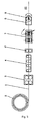
- FIG. 1 depicts in idealization the process of production and its kinematic requirements, according to the present invention.
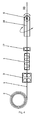
- FIG. 2 schematically depicts one of the systems that implement the process of production of three-dimensional products according to the present invention.
- FIG. 3 depicts in idealization a process of production of the three-dimensional products according to the state of the art.
- FIG. 4 depicts in idealization a second process of production of the three-dimensional products according to the state of the art.
- the process may be understood to comprise several steps.
- the wire 1, rod, rebar, or other suitable material 1 able to undergo plastic deformation, originating from spool 2 is advanced 3, is straightened 4, there occurs a measurement 17 of its length of the advanced material, and afterwards the material 1 passes sequentially from two arrangements 7, 10 of which the first 7 can hold the material 1 and rotate it around the longitudinal axis X, while the second 10 can rotate around the longitudinal axis X of the material 1, having the capability to bend the material 1 at a desired and predetermined angle and to cut it 6.
- this process it is possible to effectively choose from these two ways of creating the third dimension in the entire product or in a portion thereof, the more suitable and faster, each time.
- one can significantly reduce the time of production of the product, independent of its shape, its dimensions and its other geometric characteristics.
- a process for production of three-dimensional products from wire 1, rod, rebar, or other suitable material of any cross-section, originating from a spool 2, and capable of undergoing plastic deformation may comprise advancement 3 of material 1, measuring 17 of the advanced length, and straightening 4. Bending is effected with a bending means 5, that has the ability to rotate around the longitudinal axis X of the wire 1 and to bend the material 1 plastically, at-will, at selected and predetermined angles in different planes that may be different amongst themselves within the same shape.
- a final cutting 6 may occur upon completion of the three-dimensional product.
- the process is characterized in that according to the form and individual geometric characteristics and the dimensions of the for-production three-dimensional product it is possible to generate bendings in different planes.
- the bending means 5 for generating a different-plane bending or a second suitable means 7 with which is held fixed the wire 1 at one location and gripped at another location so as to be twisted around its longitudinal axis X, securing thus the most suitable and fastest manner of generation of individual portions of the product so as to improve the time for its production.
- a process according to the immediately preceding paragraph may be further characterized in that the location of twisting of material 1 is located after the location at which the material is held fixed.
- a process according to either of the two preceding paragraphs may be further characterized in that the twisting of material 1 around its longitudinal axis X may be made with right directional twist and left directional twist.
- the process may be implemented in an innovative system 8 which comprises an advancement mechanism 3,9 of wire 1 originating from spool 2. Also included are a straightening mechanism 11, 4 that straightens the material 1; an arrangement 18, 17 for measuring length of the material advanced; an arrangement 14, 7 able to hold the material with suitable stationary grippers 15 and simultaneously with other rotating grippers 16, which grip the material, to twist it at desired angle around its longitudinal axis X; a bending mechanism 12 that may bend the material plastically in one plane and simultaneously may rotate at a suitable angle around the longitudinal axis X of the material 1, capable thus to generate at-will selected and predetermined bendings on different planes, which bendings may be different amongst themselves within the same shape; and a cutting arrangement 13, 6 that may be carried by the bending mechanism.
- a system 8 for the production of three-dimensional products from wire 1 or rod, rebar, or other suitable material of any cross-section capable of undergoing plastic deformation may comprise an advancement mechanism 9 suitable for advancing the material originating from spool 2, a suitable straightening mechanism 11 that straightens the advancing material 1, and a length measuring arrangement 18 towards which advances the material.
- a bending mechanism 12 that can bend the material plastically on one plane and also is able to rotate to a desired angle around the longitudinal axis X of the wire 1, capable thus of generating at-will selected and predetermined bendings in different planes, which may be different amongst themselves within the same shape and which bending mechanism 12 may carry a cutting arrangement 13 for the material.
- the system 8 is characterized in that between the straightening mechanism 11 and the bending mechanism 12, that bends the material in the plane and also in the space, is interposed a gripper arrangement 14, able to hold the material with suitable stationary grippers 15 and simultaneously with other grippers 16 to twist it to a desired angle around the longitudinal axis X deforming it plastically at a desired location, so that the bends that have been made by the bending mechanism 12 may change plane.
- Either the bending mechanism 12 rotation, or the arrangement 14 may be energized at choice according to the geometric characteristics of the for-production shape, producing thus three-dimensional products from wire 1 or other suitable material capable of undergoing plastic deformation, with the suitable and best choice of advancement, bending and torsion and with the best speed corresponding with the dimensions and the requirements of the shape, each time.
- a system 8 according to the immediately preceding paragraph may be further characterized in that the arrangement 14 that is able to hold steady the material with suitable fixed grippers 15 and simultaneously with other rotating grippers 16 to twist it to a desired angle around its longitudinal axis X to deform it plastically at a desired location, is located between the straightening mechanism 11 and the bending mechanism 12.
- a system 8 according to any one of the two immediately preceding paragraphs may be further characterized in that the arrangement 14 holds steady the material with suitable grippers 15 and simultaneously with other grippers 16 may twist it to a desired angle around its longitudinal axis X with either right directional twist and left directional twist.
- a system 8 according to any one of the three immediately preceding paragraphs may be further characterized in that the supervision, the coordination and the control of all the functions of the process of production of the three-dimensional product are made by a suitable electronic computer, in which are entered the necessary characteristics of the for-production three-dimensional product.
- the individual elements and mechanisms that comprise the system 8 according to the present invention may be arranged in series, so that the arrangement 14 is located between the straightening mechanism 11 and the bending mechanism 12.
- the layout 8 according to the present invention may work wire 1, rods or other suitable material of any cross section, able to undergo plastic deformation.
- the present invention is not limited in any manner to the example described and in-the-drawing-portrayed implementation, but may be implemented in many forms and dimensions without abandoning the region of protection of the invention. Furthermore, in the implementation of the invention, the materials that are used as well as the dimensions of the individual elements can be in accordance with the requirements of the particular construction.
Abstract
Description
- The invention relates to a process of production of three-dimensional products from wire, rods, rebar, or other suitable material of any cross-section, capable of undergoing plastic deformation, and to a system which implements this process. The three-dimensional products may find use in a broad field of applications and cover a very large spectrum of shapes.
-
US 5170654 A (ANAGNOSTOPOULOS) 15.12.1992 disclosed an automatic bending machine wherein wire is advanced to astraightening mechanism 2 and passes through ameasuring mechanism 3. With reference to Figure 1 of this prior patent, abending mechanism 6 bends the wire in a plane, and acutter 7 is used for cutting the formed product from the wire. Furthermore, afixed gripper 8 and arotating gripper 9 comprise a mechanism that is found between the straightener 4 and thebending mechanism 6, this mechanism functioning to hold the material withfixed gripper 8 and simultaneously rotate the material about its longitudinal axis X with therotating gripper 9. This is explained at columns 3-5 ofUS5170654 . This system permits the production of some three-dimensional products from wire. - A different solution to the problem of producing three-dimensional products from wire, rods, or other suitable material was given in
US 4799373 A (BENTON) 24.01.1989 . With initial reference to Figure 3 of this prior patent, the worked material 24 is advanced by afeed unit 14 and is measured by a measuring system 36, 38. With further regard to Figure 1 of this prior patent, astraightening mechanism 12 straightens the material, while a bending mechanism 20 may bend the wire in one plane and may rotate in its entirety about the longitudinal axis of the material 24, in both directions as indicated in Figure 1 thereof, and as explained at column 4, lines 40-54 of this prior patent. A cutter 76 is included. As explained atcolumn 1, lines 34-36, this machine permits the production of some three-dimensional products from wire, tubing, or other elongate material. - Thus, it may be understood that the in-question three-dimensional products are produced currently in the following ways:
- (a) With reference to FIG. 3 of the appended drawings, the products may be produced with the aid of automatic machines which include an arrangement of
advancement mechanism 3, system for straightening 4, system for measuring ofadvanced length 17, a bending mechanism 5 that is fixed and bends thewire 1 in one plane thereby generating only planar forms, and which automatic machines include amechanism 7, that is found between the straightener 4 and the bending mechanism 5 and that holds the material with suitable grippers and simultaneously with other grippers twists it around its longitudinal axis X. A system for cutting 6 of thewire 1 may typically be included. - (b) With reference to FIG. 4 of the appended drawings, the products may be produced with the aid of automatic machines which include an arrangement of
advancement mechanism 3, straightener 4, a system for measuring ofadvanced length 17, and abending mechanism 10 that may bend thewire 1 in one plane and afterwards may rotate in its entirety around the longitudinal axis X of thewire 1 and effect bending again in another plane. Furthermore, asystem 6 for cutting thewire 1 may typically be included. - In the first process (a) referred to above, and in automatic machines of this first type, for the generation of the third dimension the material is twisted around its own longitudinal axis X, so that the already-produced portion of the shape comes to the suitable angle in relation to the bending tools. There follows the bending generating the new plane. This way is advisable for the generation of small sides because of the speed which characterizes it. However, for the generation of large sides, such a twisting has the disadvantage that it must occur quite slowly, because the large moment of inertia of the material of the already produced portion of the shape tends to induce vibrations in or to deform the already produced angles and sides.
- In marked contrast, in the second process (b) referred to above, and in automatic machines of the second type, for the generation of the third dimension the
entire bending mechanism 10 is rotated around the longitudinal axis X of thewire 1 so that the bending tools arrive at a suitable location for there to occur afterwards the bending of the material at the desired angle. This manner of controlled generation of bends in different planes within a single product form is advisable when it is necessary to generate large sides, because it is not necessary, as in the first process (a) referred to above, to turn in its entirety the already produced shape by twisting it at suitable angle about the material's longitudinal axis X. - A great disadvantage in each of the above-described state-of-the-art processes and in machines of the these first and second types is that each one of them respectively provides only one respective way for generating the third dimension in a shape. This entails great limitations primarily as to productivity, taking into consideration that the in-question products in almost all cases must be produced in very large numbers. It may be readily understood that in shapes that have both large and small sides, whichever process is employed has the consequence of significant delay in production. That is because with the first process and automatic machines of the first type (a), the delay will occur during the generation of the large sides; while in the second process and automatic machines of the second type (b) the delay will occur during the generation of the small sides of the product space as the entire bending mechanism is rotated.
- A process according to the present invention and an exemplary system that implements it, as presented herein, effect the automated production of three-dimensional products from wire, rod, rebar, or other suitable material of any cross-section able to undergo plastic formation, and provide the possibility, for each segment or portion of the under-production product, of selecting the faster and best manner of production according to its geometry and its dimensions. The invention provides for the first time the breakthrough coexistence, within one system, of
arrangement 14 andbending mechanism 12 with the individual characteristics referred to above, thus providing the heretofore unenvisioned and unknown capability of selectively choosing and energizing within the same shape one or the other of themechanisms - In relation to the enumerated disadvantages of the methods and machines that existed, explained above, and in contrast thereto, the present invention provides the following among its specific advantages. Taking into consideration that these three-dimensional products are usually produced in very large number:
- Flexibility in production is significantly increased
- The time for production of the three-dimensional products is significantly shortened.
- The cost of production is reduced to a great degree.
- The details of the process and of the system according to the present invention will be understood from the following description and from the appended drawings, where:
- FIG. 1 depicts in idealization the process of production and its kinematic requirements, according to the present invention.
- FIG. 2 schematically depicts one of the systems that implement the process of production of three-dimensional products according to the present invention.
- FIG. 3 depicts in idealization a process of production of the three-dimensional products according to the state of the art.
- FIG. 4 depicts in idealization a second process of production of the three-dimensional products according to the state of the art.
- The process may be understood to comprise several steps. With reference to FIG. 1, the
wire 1, rod, rebar, or othersuitable material 1 able to undergo plastic deformation, originating fromspool 2, is advanced 3, is straightened 4, there occurs ameasurement 17 of its length of the advanced material, and afterwards thematerial 1 passes sequentially from twoarrangements material 1 and rotate it around the longitudinal axis X, while the second 10 can rotate around the longitudinal axis X of thematerial 1, having the capability to bend thematerial 1 at a desired and predetermined angle and to cut it 6. With this process, it is possible to effectively choose from these two ways of creating the third dimension in the entire product or in a portion thereof, the more suitable and faster, each time. Thus, with the flexibility afforded by this process one can significantly reduce the time of production of the product, independent of its shape, its dimensions and its other geometric characteristics. - Accordingly, there is provided a process for production of three-dimensional products from
wire 1, rod, rebar, or other suitable material of any cross-section, originating from aspool 2, and capable of undergoing plastic deformation. The process may compriseadvancement 3 ofmaterial 1, measuring 17 of the advanced length, and straightening 4. Bending is effected with a bending means 5, that has the ability to rotate around the longitudinal axis X of thewire 1 and to bend thematerial 1 plastically, at-will, at selected and predetermined angles in different planes that may be different amongst themselves within the same shape. Afinal cutting 6 may occur upon completion of the three-dimensional product. The process is characterized in that according to the form and individual geometric characteristics and the dimensions of the for-production three-dimensional product it is possible to generate bendings in different planes. For each portion of the for-production shape there is selected separately, either the bending means 5 for generating a different-plane bending, or a secondsuitable means 7 with which is held fixed thewire 1 at one location and gripped at another location so as to be twisted around its longitudinal axis X, securing thus the most suitable and fastest manner of generation of individual portions of the product so as to improve the time for its production. - A process according to the immediately preceding paragraph may be further characterized in that the location of twisting of
material 1 is located after the location at which the material is held fixed. - Furthermore, a process according to either of the two preceding paragraphs may be further characterized in that the twisting of
material 1 around its longitudinal axis X may be made with right directional twist and left directional twist. - With reference to FIGS. 1-2, the process may be implemented in an
innovative system 8 which comprises anadvancement mechanism wire 1 originating fromspool 2. Also included are astraightening mechanism 11, 4 that straightens thematerial 1; anarrangement arrangement stationary grippers 15 and simultaneously with otherrotating grippers 16, which grip the material, to twist it at desired angle around its longitudinal axis X; abending mechanism 12 that may bend the material plastically in one plane and simultaneously may rotate at a suitable angle around the longitudinal axis X of thematerial 1, capable thus to generate at-will selected and predetermined bendings on different planes, which bendings may be different amongst themselves within the same shape; and acutting arrangement - Accordingly, in a version of the invention there is provided a
system 8 for the production of three-dimensional products fromwire 1 or rod, rebar, or other suitable material of any cross-section capable of undergoing plastic deformation. Thesystem 8 may comprise anadvancement mechanism 9 suitable for advancing the material originating fromspool 2, asuitable straightening mechanism 11 that straightens the advancingmaterial 1, and alength measuring arrangement 18 towards which advances the material. Also included are an arrangement of abending mechanism 12 that can bend the material plastically on one plane and also is able to rotate to a desired angle around the longitudinal axis X of thewire 1, capable thus of generating at-will selected and predetermined bendings in different planes, which may be different amongst themselves within the same shape and whichbending mechanism 12 may carry acutting arrangement 13 for the material. Thesystem 8 is characterized in that between thestraightening mechanism 11 and thebending mechanism 12, that bends the material in the plane and also in the space, is interposed agripper arrangement 14, able to hold the material with suitablestationary grippers 15 and simultaneously withother grippers 16 to twist it to a desired angle around the longitudinal axis X deforming it plastically at a desired location, so that the bends that have been made by thebending mechanism 12 may change plane. Either thebending mechanism 12 rotation, or thearrangement 14 may be energized at choice according to the geometric characteristics of the for-production shape, producing thus three-dimensional products fromwire 1 or other suitable material capable of undergoing plastic deformation, with the suitable and best choice of advancement, bending and torsion and with the best speed corresponding with the dimensions and the requirements of the shape, each time. - A
system 8 according to the immediately preceding paragraph may be further characterized in that thearrangement 14 that is able to hold steady the material with suitable fixedgrippers 15 and simultaneously with otherrotating grippers 16 to twist it to a desired angle around its longitudinal axis X to deform it plastically at a desired location, is located between the straighteningmechanism 11 and thebending mechanism 12. - Furthermore, a
system 8 according to any one of the two immediately preceding paragraphs may be further characterized in that thearrangement 14 holds steady the material withsuitable grippers 15 and simultaneously withother grippers 16 may twist it to a desired angle around its longitudinal axis X with either right directional twist and left directional twist. - Furthermore, a
system 8 according to any one of the three immediately preceding paragraphs may be further characterized in that the supervision, the coordination and the control of all the functions of the process of production of the three-dimensional product are made by a suitable electronic computer, in which are entered the necessary characteristics of the for-production three-dimensional product. - The individual elements and mechanisms that comprise the
system 8 according to the present invention may be arranged in series, so that thearrangement 14 is located between the straighteningmechanism 11 and thebending mechanism 12. - As has been explained, the
layout 8 according to the present invention may workwire 1, rods or other suitable material of any cross section, able to undergo plastic deformation. - The coordination and control of all the functions of the process of production of the three-dimensional products are effected by a suitable electronic computer, in which are entered all necessary product characteristics for the production of the product and via which may be chosen in which portions of the product, which
mechanism - The present invention is not limited in any manner to the example described and in-the-drawing-portrayed implementation, but may be implemented in many forms and dimensions without abandoning the region of protection of the invention. Furthermore, in the implementation of the invention, the materials that are used as well as the dimensions of the individual elements can be in accordance with the requirements of the particular construction.
- With regard to the appended claims, in every claim, where reference to technical characteristics is made and followed by reference numerals, it should be understood that these are included only to increase the comprehensibility of the claims, and in this way the reference numerals do not affect the treatment of the claim elements, which are identified by way of example with them.
Claims (9)
- A system (8) for producing three-dimensional products from wire (1), rod, rebar, or other material of any cross-section capable of undergoing plastic deformation, comprising:an advancement mechanism (9,3) for advancing material (1);a straightening mechanism (11,4) for straightening the advancing material (1); a length-measuring arrangement (18,17) for measuring the length of material (1) advanced;a bending mechanism (12,10) for bending the material (1) in one plane, said bending mechanism (12,10) being selectively rotatable to a desired angle around a longitudinal axis (X) of the material (1) to generate selected predetermined bends of the material (1) in different planes;and characterized by:a gripper arrangement (14,7) interposed between said straightening mechanism (11,4) and said bending mechanism (12,10);said gripper arrangement (14,7) including stationary grippers (15);said gripper arrangement (14,7) including rotating grippers (16) for selectively twisting material (1) around its longitudinal axis (X).
- The system (8) for producing three-dimensional products from wire (1), rod, rebar, or other material of any cross-section capable of undergoing plastic deformation, as claimed in Claim 1, further characterized by:a cutting arrangement (13,6) carried by said bending mechanism (12,10).
- The system (8) for producing three-dimensional products from wire (1), rod, rebar, or other material of any cross-section capable of undergoing plastic deformation, as claimed in any of Claims 1 or 2, further characterized by:said rotating grippers (16) configured to twist the material (1) around its longitudinal axis (X) with right-directional twist and left-directional twist.
- The system (8) for producing three-dimensional products from wire (1), rod, rebar, or other material of any cross-section capable of undergoing plastic deformation, as claimed in any of Claims 1, 2 or 3, further characterized by:a suitable electronic computer for supervision, coordination, and control of the production of the three-dimensional products.
- A process for production of three-dimensional products from wire (1), rod, rebar, or other suitable material of any cross-section capable of undergoing plastic deformation, comprising the steps of:advancing (3) the material (1);measuring (17) the advanced length of the material (1);straightening (4) the material (1);bending (10) the material (1) with a bending means (10,12) configured to rotate around the longitudinal axis (X) of the material (1) and to bend material (1) plastically at-will at selected, predetermined angles in different planes;cutting (6) the material (1) upon completion of the three-dimensional product; and characterized by the step of:selecting either the bending means (10,12), or a second means (7) that holds the material (1) fixed at a first location and simultaneously twists it around its longitudinal axis (X) by gripping it at a second location, to generate bendings in different planes.
- The process for production of three-dimensional products from wire (1), rod, rebar, or other suitable material of any cross-section capable of undergoing plastic deformation as claimed in Claim 5, further characterized by the step of:twisting the material (1) around its longitudinal axis (X) with said second means (7), in a right-directional twist or a left-directional twist.
- The process for production of three-dimensional products from wire (1), rod, rebar, or other suitable material of any cross-section capable of undergoing plastic deformation as claimed any of Claims 5 or 6, further characterized by the step of:locating said second location after said first location.
- The process for production of three-dimensional products from wire (1), rod, rebar, or other suitable material of any cross-section capable of undergoing plastic deformation as claimed any of Claims 5, 6 or 7, further characterized in that:said selecting of either the bending means (10,12) or a second means (7) is made according to the form and individual geometric characteristics of the for-production three-dimensional product.
- The process for production of three-dimensional products from wire (1), rod, rebar, or other suitable material of any cross-section capable of undergoing plastic deformation as claimed any of Claims 5, 6, 7 or 8, further characterized in that:said selecting of either the bending means (10,12) or a second means (7) is made to secure the most suitable and fastest manner of generation of individual portions of the product.
Applications Claiming Priority (1)
| Application Number | Priority Date | Filing Date | Title |
|---|---|---|---|
| GR20060100545A GR1005986B (en) | 2006-10-03 | 2006-10-03 | Method and system for the production of three-dimensional products. |
Publications (2)
| Publication Number | Publication Date |
|---|---|
| EP1908537A1 true EP1908537A1 (en) | 2008-04-09 |
| EP1908537B1 EP1908537B1 (en) | 2011-01-05 |
Family
ID=38669852
Family Applications (1)
| Application Number | Title | Priority Date | Filing Date |
|---|---|---|---|
| EP07117186A Active EP1908537B1 (en) | 2006-10-03 | 2007-09-25 | Process and system for production of three-dimensional products from wire |
Country Status (7)
| Country | Link |
|---|---|
| US (1) | US7878038B2 (en) |
| EP (1) | EP1908537B1 (en) |
| AT (1) | ATE494084T1 (en) |
| DE (1) | DE602007011704D1 (en) |
| DK (1) | DK1908537T3 (en) |
| ES (1) | ES2358449T3 (en) |
| GR (1) | GR1005986B (en) |
Cited By (6)
| Publication number | Priority date | Publication date | Assignee | Title |
|---|---|---|---|---|
| CN101961763A (en) * | 2010-10-28 | 2011-02-02 | 天津市建科机械制造有限公司 | Wire twisting device of three-dimensional forming machine for steel bars |
| ITBO20110048A1 (en) * | 2011-02-04 | 2012-08-05 | Anton Massimo Galluccio | METHOD AND EQUIPMENT FOR REALIZING REINFORCED CONCRETE REINFORCEMENTS |
| ITUD20110116A1 (en) * | 2011-07-20 | 2013-01-21 | Piegatrici Macch Elettr | MACHINE FOR BENDING METAL BARS AND ITS PROCEDURE |
| CN109365698A (en) * | 2018-09-13 | 2019-02-22 | 葛骏驰 | A kind of full-automatic individual wire hair curling machine and its processing method |
| DE102018215501A1 (en) * | 2018-09-12 | 2020-03-12 | Wafios Aktiengesellschaft | Process for producing a bent part and bending machine for carrying out the process |
| US10926315B2 (en) | 2014-04-01 | 2021-02-23 | Antonios Anagnostopoulos | Systems and processes for feeding longitudinal wires or rods to mesh producing machines |
Families Citing this family (17)
| Publication number | Priority date | Publication date | Assignee | Title |
|---|---|---|---|---|
| US8549888B2 (en) * | 2008-04-04 | 2013-10-08 | Nuvasive, Inc. | System and device for designing and forming a surgical implant |
| JP4708508B1 (en) * | 2010-04-07 | 2011-06-22 | 株式会社太洋 | Fully automatic pipe bender |
| US20140033782A1 (en) * | 2012-01-24 | 2014-02-06 | Fci Holdings Delaware, Inc. | Method and Apparatus for Continuous Bulbing of Stranded Cable |
| US9156077B2 (en) * | 2012-03-29 | 2015-10-13 | L&P Property Management Company | Method of making border wire |
| CN103212653B (en) * | 2013-03-26 | 2014-11-26 | 苏州盟川自动化科技有限公司 | Automatic wire feeding, cutting off and bending device for fuse wire |
| US20170014725A1 (en) * | 2015-07-15 | 2017-01-19 | Ignacio Marc Asperas | Method Of Manufacturing A Light Weight Ball Configured To Adhere & Maintain Snow For A Snowman |
| CN106694747A (en) * | 2015-07-27 | 2017-05-24 | 青岛欧勃亚商用设备有限公司 | Three-dimensional iron wire formation integrated machine and method |
| CN105537457A (en) * | 2016-02-03 | 2016-05-04 | 建科机械(天津)股份有限公司 | Extension and contraction device for rebar hoop bending machine |
| CN106938307A (en) * | 2017-03-29 | 2017-07-11 | 国网山东省电力公司菏泽供电公司 | A kind of intelligent transversal machine |
| DE102017217032A1 (en) * | 2017-09-26 | 2019-03-28 | Wafios Aktiengesellschaft | Method and bending machine for producing bent parts from flat material |
| CN109531771B (en) * | 2018-12-07 | 2020-03-24 | 中国建筑材料科学研究总院有限公司 | Equipment and method for preparing building structure based on 3D printing |
| CN110523881B (en) * | 2019-09-30 | 2021-06-22 | 邵东智能制造技术研究院有限公司 | Reinforcing bar material loading device of buckling |
| CN110560602A (en) * | 2019-09-30 | 2019-12-13 | 汪海军 | Machine tool of line folding machine |
| CN111215566B (en) * | 2019-11-29 | 2021-06-15 | 高晖 | Reinforcing bar system of flare-outing for building machinery |
| CN111730007B (en) * | 2020-08-07 | 2022-06-24 | 山东睿煜矿用材料加工有限公司 | Straightening device of reinforcing steel bar hoop bending machine |
| CN113636771B (en) * | 2021-09-06 | 2023-04-28 | 浙江理工大学 | Arc-shaped steel fiber, manufacturing mold and method and concrete using steel fiber |
| CN113754332A (en) * | 2021-09-06 | 2021-12-07 | 浙江理工大学 | Three-dimensional steel fiber, manufacturing mold and method and concrete applying three-dimensional steel fiber |
Citations (3)
| Publication number | Priority date | Publication date | Assignee | Title |
|---|---|---|---|---|
| EP0231092A2 (en) * | 1986-01-29 | 1987-08-05 | Ronald Edward Benton | Bending machine |
| US5170654A (en) * | 1990-04-06 | 1992-12-15 | Anagnostopoulos Panagiotis A | Method for wire bending in three dimensions |
| WO2003103874A1 (en) * | 2002-06-05 | 2003-12-18 | Antonios Anagnostopoulos | Method and machine for simultaneous and parallel production of similar products, through straightening and bending of wires, wire rods, metal tubes or other material of prismatic cross section. |
Family Cites Families (9)
| Publication number | Priority date | Publication date | Assignee | Title |
|---|---|---|---|---|
| US813215A (en) * | 1904-04-29 | 1906-02-20 | Charles A Juengst | Stapling-machine. |
| US3922901A (en) * | 1973-11-29 | 1975-12-02 | Weldun Tool & Engineering Co | Apparatus for bending tubing |
| DE3415006A1 (en) * | 1984-04-19 | 1985-11-07 | Helge Dr. 8000 München Fischer-Brandies | DENTAL PROCESS AND DEVICE FOR BENDING AND TURNING A WIRE PIECE |
| GR890100232A (en) * | 1989-04-11 | 1991-09-27 | Panagiotis Anagnostopoulos | Added flexion system for wire works for the construction of tridensional flat forms |
| DE4229294C1 (en) * | 1992-09-02 | 1993-12-16 | Wafios Maschinen Wagner | Wire-shaping machine esp. for mfr. of springs - has wire-clamping rollers turning in either direction together round the wire guide axis and intermittently and programme-controlled |
| DE19816403C2 (en) * | 1998-04-11 | 2001-06-13 | Wafios Maschinen Wagner | Wire forming device with a wire brake device and wire forming method |
| FR2806943B1 (en) * | 2000-04-03 | 2002-08-16 | Macsoft | ERASABLE FOLDING NOSE BAR BENDING MACHINE |
| US6644079B2 (en) * | 2001-12-21 | 2003-11-11 | Burr Oak Tool And Gauge Company, Inc. | Hairpin bender with leg length measurement and adjustment feature |
| US7240528B2 (en) * | 2004-11-22 | 2007-07-10 | Lingualcare, Inc. | Method and device for shaping an orthodontic archwire |
-
2006
- 2006-10-03 GR GR20060100545A patent/GR1005986B/en active IP Right Grant
-
2007
- 2007-09-25 EP EP07117186A patent/EP1908537B1/en active Active
- 2007-09-25 US US11/861,277 patent/US7878038B2/en not_active Expired - Fee Related
- 2007-09-25 ES ES07117186T patent/ES2358449T3/en active Active
- 2007-09-25 DK DK07117186.2T patent/DK1908537T3/en active
- 2007-09-25 AT AT07117186T patent/ATE494084T1/en active
- 2007-09-25 DE DE602007011704T patent/DE602007011704D1/en active Active
Patent Citations (3)
| Publication number | Priority date | Publication date | Assignee | Title |
|---|---|---|---|---|
| EP0231092A2 (en) * | 1986-01-29 | 1987-08-05 | Ronald Edward Benton | Bending machine |
| US5170654A (en) * | 1990-04-06 | 1992-12-15 | Anagnostopoulos Panagiotis A | Method for wire bending in three dimensions |
| WO2003103874A1 (en) * | 2002-06-05 | 2003-12-18 | Antonios Anagnostopoulos | Method and machine for simultaneous and parallel production of similar products, through straightening and bending of wires, wire rods, metal tubes or other material of prismatic cross section. |
Cited By (10)
| Publication number | Priority date | Publication date | Assignee | Title |
|---|---|---|---|---|
| CN101961763A (en) * | 2010-10-28 | 2011-02-02 | 天津市建科机械制造有限公司 | Wire twisting device of three-dimensional forming machine for steel bars |
| CN101961763B (en) * | 2010-10-28 | 2012-12-05 | 建科机械(天津)股份有限公司 | Wire twisting device of three-dimensional forming machine for steel bars |
| ITBO20110048A1 (en) * | 2011-02-04 | 2012-08-05 | Anton Massimo Galluccio | METHOD AND EQUIPMENT FOR REALIZING REINFORCED CONCRETE REINFORCEMENTS |
| WO2012104412A1 (en) * | 2011-02-04 | 2012-08-09 | Anton Massimo Galluccio | Method and apparatus for making reinforcements for reinforced concrete |
| ITUD20110116A1 (en) * | 2011-07-20 | 2013-01-21 | Piegatrici Macch Elettr | MACHINE FOR BENDING METAL BARS AND ITS PROCEDURE |
| WO2013011373A1 (en) | 2011-07-20 | 2013-01-24 | M.E.P. Macchine Elettroniche Piegatrici Spa | Machine for bending metal bars and corresponding method |
| US10926315B2 (en) | 2014-04-01 | 2021-02-23 | Antonios Anagnostopoulos | Systems and processes for feeding longitudinal wires or rods to mesh producing machines |
| DE102018215501A1 (en) * | 2018-09-12 | 2020-03-12 | Wafios Aktiengesellschaft | Process for producing a bent part and bending machine for carrying out the process |
| CN109365698A (en) * | 2018-09-13 | 2019-02-22 | 葛骏驰 | A kind of full-automatic individual wire hair curling machine and its processing method |
| CN109365698B (en) * | 2018-09-13 | 2020-06-09 | 葛骏驰 | Full-automatic single steel wire wool rolling machine and processing method thereof |
Also Published As
| Publication number | Publication date |
|---|---|
| US7878038B2 (en) | 2011-02-01 |
| US20080078226A1 (en) | 2008-04-03 |
| ATE494084T1 (en) | 2011-01-15 |
| GR20060100545A (en) | 2008-05-21 |
| ES2358449T3 (en) | 2011-05-10 |
| EP1908537B1 (en) | 2011-01-05 |
| DK1908537T3 (en) | 2011-04-04 |
| GR1005986B (en) | 2008-07-10 |
| DE602007011704D1 (en) | 2011-02-17 |
Similar Documents
| Publication | Publication Date | Title |
|---|---|---|
| EP1908537B1 (en) | Process and system for production of three-dimensional products from wire | |
| CN103765335B (en) | For method and system and the forming machine of the programming of the control of multiaxial type forming machine | |
| EP1852195B1 (en) | Method and Machine for Production of Three-Dimensional Stirrups | |
| EP2822714B1 (en) | Method and system for bending spacers | |
| KR102189749B1 (en) | Drawing and Straightening Apparatus for Metal Wire, and Corresponding Drawing and Straightening Method | |
| CN111225753B (en) | Machine and method for bending elongated elements, preferably metal, such as bars, rods, profiles and the like | |
| EP2714296B1 (en) | Apparatus for making stirrups | |
| EP0209876A2 (en) | Universal bending machine and respective method for bending | |
| RU2678852C2 (en) | Apparatus for bending oblong metal products, such as bars, round pieces or metal wires, and corresponding bending method | |
| US20050103080A1 (en) | Method and machine for simultaneous and parallel production of similar products, through straightening and bending of wires, wire rods, metal tubes or other material of prismatic cross section | |
| WO2013011373A1 (en) | Machine for bending metal bars and corresponding method | |
| JPS62130730A (en) | Forming method for zigzag spring | |
| WO2016194482A1 (en) | Device for manufacturing coil spring and method for manufacturing coil spring | |
| EP1478476B1 (en) | Method and mechanism for feeding of wires, wire rods, tubes or other material of prismatic cross section from different feeding lines to one processing line | |
| JP2020506805A (en) | Apparatus and method for manufacturing wire mesh | |
| WO2023275840A1 (en) | Method of bending and bending machine for the execution of a method of bending | |
| UA20935U (en) | Method for treatment of wire billet | |
| PL113914B1 (en) | Spring making apparatus especially for making double volute springs |
Legal Events
| Date | Code | Title | Description |
|---|---|---|---|
| PUAI | Public reference made under article 153(3) epc to a published international application that has entered the european phase |
Free format text: ORIGINAL CODE: 0009012 |
|
| AK | Designated contracting states |
Kind code of ref document: A1 Designated state(s): AT BE BG CH CY CZ DE DK EE ES FI FR GB GR HU IE IS IT LI LT LU LV MC MT NL PL PT RO SE SI SK TR |
|
| AX | Request for extension of the european patent |
Extension state: AL BA HR MK RS |
|
| 17P | Request for examination filed |
Effective date: 20080328 |
|
| 17Q | First examination report despatched |
Effective date: 20080528 |
|
| AKX | Designation fees paid |
Designated state(s): AT BE BG CH CY CZ DE DK EE ES FI FR GB GR HU IE IS IT LI LT LU LV MC MT NL PL PT RO SE SI SK TR |
|
| RAP1 | Party data changed (applicant data changed or rights of an application transferred) |
Owner name: ANAGNOSTOPOULOS, ANTONIOS |
|
| RIN1 | Information on inventor provided before grant (corrected) |
Inventor name: ANAGNOSTOPOULOS, ANTONIOS |
|
| GRAP | Despatch of communication of intention to grant a patent |
Free format text: ORIGINAL CODE: EPIDOSNIGR1 |
|
| GRAS | Grant fee paid |
Free format text: ORIGINAL CODE: EPIDOSNIGR3 |
|
| GRAA | (expected) grant |
Free format text: ORIGINAL CODE: 0009210 |
|
| AK | Designated contracting states |
Kind code of ref document: B1 Designated state(s): AT BE BG CH CY CZ DE DK EE ES FI FR GB GR HU IE IS IT LI LT LU LV MC MT NL PL PT RO SE SI SK TR |
|
| REG | Reference to a national code |
Ref country code: GB Ref legal event code: FG4D |
|
| REG | Reference to a national code |
Ref country code: CH Ref legal event code: EP |
|
| REG | Reference to a national code |
Ref country code: IE Ref legal event code: FG4D |
|
| REF | Corresponds to: |
Ref document number: 602007011704 Country of ref document: DE Date of ref document: 20110217 Kind code of ref document: P |
|
| REG | Reference to a national code |
Ref country code: DE Ref legal event code: R096 Ref document number: 602007011704 Country of ref document: DE Effective date: 20110217 |
|
| REG | Reference to a national code |
Ref country code: CH Ref legal event code: NV Representative=s name: ROSENICH PAUL; GISLER CHRISTIAN PATENTBUERO PAUL R |
|
| REG | Reference to a national code |
Ref country code: DK Ref legal event code: T3 |
|
| REG | Reference to a national code |
Ref country code: SE Ref legal event code: TRGR |
|
| REG | Reference to a national code |
Ref country code: NL Ref legal event code: T3 |
|
| REG | Reference to a national code |
Ref country code: ES Ref legal event code: FG2A Ref document number: 2358449 Country of ref document: ES Kind code of ref document: T3 Effective date: 20110427 |
|
| PG25 | Lapsed in a contracting state [announced via postgrant information from national office to epo] |
Ref country code: SI Free format text: LAPSE BECAUSE OF FAILURE TO SUBMIT A TRANSLATION OF THE DESCRIPTION OR TO PAY THE FEE WITHIN THE PRESCRIBED TIME-LIMIT Effective date: 20110105 |
|
| LTIE | Lt: invalidation of european patent or patent extension |
Effective date: 20110105 |
|
| PG25 | Lapsed in a contracting state [announced via postgrant information from national office to epo] |
Ref country code: LT Free format text: LAPSE BECAUSE OF FAILURE TO SUBMIT A TRANSLATION OF THE DESCRIPTION OR TO PAY THE FEE WITHIN THE PRESCRIBED TIME-LIMIT Effective date: 20110105 Ref country code: PT Free format text: LAPSE BECAUSE OF FAILURE TO SUBMIT A TRANSLATION OF THE DESCRIPTION OR TO PAY THE FEE WITHIN THE PRESCRIBED TIME-LIMIT Effective date: 20110505 Ref country code: LV Free format text: LAPSE BECAUSE OF FAILURE TO SUBMIT A TRANSLATION OF THE DESCRIPTION OR TO PAY THE FEE WITHIN THE PRESCRIBED TIME-LIMIT Effective date: 20110105 Ref country code: IS Free format text: LAPSE BECAUSE OF FAILURE TO SUBMIT A TRANSLATION OF THE DESCRIPTION OR TO PAY THE FEE WITHIN THE PRESCRIBED TIME-LIMIT Effective date: 20110505 Ref country code: GR Free format text: LAPSE BECAUSE OF FAILURE TO SUBMIT A TRANSLATION OF THE DESCRIPTION OR TO PAY THE FEE WITHIN THE PRESCRIBED TIME-LIMIT Effective date: 20110406 |
|
| PG25 | Lapsed in a contracting state [announced via postgrant information from national office to epo] |
Ref country code: BE Free format text: LAPSE BECAUSE OF FAILURE TO SUBMIT A TRANSLATION OF THE DESCRIPTION OR TO PAY THE FEE WITHIN THE PRESCRIBED TIME-LIMIT Effective date: 20110105 Ref country code: CY Free format text: LAPSE BECAUSE OF FAILURE TO SUBMIT A TRANSLATION OF THE DESCRIPTION OR TO PAY THE FEE WITHIN THE PRESCRIBED TIME-LIMIT Effective date: 20110105 Ref country code: FI Free format text: LAPSE BECAUSE OF FAILURE TO SUBMIT A TRANSLATION OF THE DESCRIPTION OR TO PAY THE FEE WITHIN THE PRESCRIBED TIME-LIMIT Effective date: 20110105 Ref country code: BG Free format text: LAPSE BECAUSE OF FAILURE TO SUBMIT A TRANSLATION OF THE DESCRIPTION OR TO PAY THE FEE WITHIN THE PRESCRIBED TIME-LIMIT Effective date: 20110405 Ref country code: PL Free format text: LAPSE BECAUSE OF FAILURE TO SUBMIT A TRANSLATION OF THE DESCRIPTION OR TO PAY THE FEE WITHIN THE PRESCRIBED TIME-LIMIT Effective date: 20110105 |
|
| PG25 | Lapsed in a contracting state [announced via postgrant information from national office to epo] |
Ref country code: EE Free format text: LAPSE BECAUSE OF FAILURE TO SUBMIT A TRANSLATION OF THE DESCRIPTION OR TO PAY THE FEE WITHIN THE PRESCRIBED TIME-LIMIT Effective date: 20110105 |
|
| PLBE | No opposition filed within time limit |
Free format text: ORIGINAL CODE: 0009261 |
|
| STAA | Information on the status of an ep patent application or granted ep patent |
Free format text: STATUS: NO OPPOSITION FILED WITHIN TIME LIMIT |
|
| PG25 | Lapsed in a contracting state [announced via postgrant information from national office to epo] |
Ref country code: RO Free format text: LAPSE BECAUSE OF FAILURE TO SUBMIT A TRANSLATION OF THE DESCRIPTION OR TO PAY THE FEE WITHIN THE PRESCRIBED TIME-LIMIT Effective date: 20110105 Ref country code: CZ Free format text: LAPSE BECAUSE OF FAILURE TO SUBMIT A TRANSLATION OF THE DESCRIPTION OR TO PAY THE FEE WITHIN THE PRESCRIBED TIME-LIMIT Effective date: 20110105 Ref country code: SK Free format text: LAPSE BECAUSE OF FAILURE TO SUBMIT A TRANSLATION OF THE DESCRIPTION OR TO PAY THE FEE WITHIN THE PRESCRIBED TIME-LIMIT Effective date: 20110105 |
|
| 26N | No opposition filed |
Effective date: 20111006 |
|
| REG | Reference to a national code |
Ref country code: DE Ref legal event code: R097 Ref document number: 602007011704 Country of ref document: DE Effective date: 20111006 |
|
| PG25 | Lapsed in a contracting state [announced via postgrant information from national office to epo] |
Ref country code: MC Free format text: LAPSE BECAUSE OF NON-PAYMENT OF DUE FEES Effective date: 20110930 |
|
| PG25 | Lapsed in a contracting state [announced via postgrant information from national office to epo] |
Ref country code: MT Free format text: LAPSE BECAUSE OF FAILURE TO SUBMIT A TRANSLATION OF THE DESCRIPTION OR TO PAY THE FEE WITHIN THE PRESCRIBED TIME-LIMIT Effective date: 20110105 |
|
| PG25 | Lapsed in a contracting state [announced via postgrant information from national office to epo] |
Ref country code: LU Free format text: LAPSE BECAUSE OF NON-PAYMENT OF DUE FEES Effective date: 20110925 |
|
| PG25 | Lapsed in a contracting state [announced via postgrant information from national office to epo] |
Ref country code: TR Free format text: LAPSE BECAUSE OF FAILURE TO SUBMIT A TRANSLATION OF THE DESCRIPTION OR TO PAY THE FEE WITHIN THE PRESCRIBED TIME-LIMIT Effective date: 20110105 |
|
| PG25 | Lapsed in a contracting state [announced via postgrant information from national office to epo] |
Ref country code: HU Free format text: LAPSE BECAUSE OF FAILURE TO SUBMIT A TRANSLATION OF THE DESCRIPTION OR TO PAY THE FEE WITHIN THE PRESCRIBED TIME-LIMIT Effective date: 20110105 |
|
| REG | Reference to a national code |
Ref country code: FR Ref legal event code: PLFP Year of fee payment: 10 |
|
| REG | Reference to a national code |
Ref country code: FR Ref legal event code: PLFP Year of fee payment: 11 |
|
| REG | Reference to a national code |
Ref country code: DE Ref legal event code: R082 Ref document number: 602007011704 Country of ref document: DE Representative=s name: PATENTBUERO PAUL ROSENICH AG, LI |
|
| REG | Reference to a national code |
Ref country code: FR Ref legal event code: PLFP Year of fee payment: 12 |
|
| PGFP | Annual fee paid to national office [announced via postgrant information from national office to epo] |
Ref country code: NL Payment date: 20190927 Year of fee payment: 13 Ref country code: SE Payment date: 20190925 Year of fee payment: 13 Ref country code: IE Payment date: 20190925 Year of fee payment: 13 Ref country code: DK Payment date: 20190925 Year of fee payment: 13 |
|
| PGFP | Annual fee paid to national office [announced via postgrant information from national office to epo] |
Ref country code: AT Payment date: 20190926 Year of fee payment: 13 |
|
| REG | Reference to a national code |
Ref country code: CH Ref legal event code: PCAR Free format text: NEW ADDRESS: ROTENBODENSTRASSE 12, 9497 TRIESENBERG (LI) |
|
| PGFP | Annual fee paid to national office [announced via postgrant information from national office to epo] |
Ref country code: CH Payment date: 20200811 Year of fee payment: 14 |
|
| REG | Reference to a national code |
Ref country code: DK Ref legal event code: EBP Effective date: 20200930 |
|
| REG | Reference to a national code |
Ref country code: NL Ref legal event code: MM Effective date: 20201001 |
|
| REG | Reference to a national code |
Ref country code: AT Ref legal event code: MM01 Ref document number: 494084 Country of ref document: AT Kind code of ref document: T Effective date: 20200925 |
|
| PG25 | Lapsed in a contracting state [announced via postgrant information from national office to epo] |
Ref country code: NL Free format text: LAPSE BECAUSE OF NON-PAYMENT OF DUE FEES Effective date: 20201001 |
|
| PG25 | Lapsed in a contracting state [announced via postgrant information from national office to epo] |
Ref country code: SE Free format text: LAPSE BECAUSE OF NON-PAYMENT OF DUE FEES Effective date: 20200926 Ref country code: IE Free format text: LAPSE BECAUSE OF NON-PAYMENT OF DUE FEES Effective date: 20200925 Ref country code: AT Free format text: LAPSE BECAUSE OF NON-PAYMENT OF DUE FEES Effective date: 20200925 |
|
| REG | Reference to a national code |
Ref country code: SE Ref legal event code: EUG |
|
| PG25 | Lapsed in a contracting state [announced via postgrant information from national office to epo] |
Ref country code: DK Free format text: LAPSE BECAUSE OF NON-PAYMENT OF DUE FEES Effective date: 20200930 |
|
| REG | Reference to a national code |
Ref country code: CH Ref legal event code: PL |
|
| PG25 | Lapsed in a contracting state [announced via postgrant information from national office to epo] |
Ref country code: LI Free format text: LAPSE BECAUSE OF NON-PAYMENT OF DUE FEES Effective date: 20210930 Ref country code: CH Free format text: LAPSE BECAUSE OF NON-PAYMENT OF DUE FEES Effective date: 20210930 |
|
| PGFP | Annual fee paid to national office [announced via postgrant information from national office to epo] |
Ref country code: GB Payment date: 20230920 Year of fee payment: 17 |
|
| PGFP | Annual fee paid to national office [announced via postgrant information from national office to epo] |
Ref country code: FR Payment date: 20230922 Year of fee payment: 17 Ref country code: DE Payment date: 20230930 Year of fee payment: 17 |
|
| PGFP | Annual fee paid to national office [announced via postgrant information from national office to epo] |
Ref country code: ES Payment date: 20231002 Year of fee payment: 17 |
|
| PGFP | Annual fee paid to national office [announced via postgrant information from national office to epo] |
Ref country code: IT Payment date: 20230927 Year of fee payment: 17 |