EP1795221A1 - Dispensing device, storage device and method for dispensing a formulation - Google Patents
Dispensing device, storage device and method for dispensing a formulation Download PDFInfo
- Publication number
- EP1795221A1 EP1795221A1 EP06000866A EP06000866A EP1795221A1 EP 1795221 A1 EP1795221 A1 EP 1795221A1 EP 06000866 A EP06000866 A EP 06000866A EP 06000866 A EP06000866 A EP 06000866A EP 1795221 A1 EP1795221 A1 EP 1795221A1
- Authority
- EP
- European Patent Office
- Prior art keywords
- insert
- dispensing device
- formulation
- storage device
- dispensing
- Prior art date
- Legal status (The legal status is an assumption and is not a legal conclusion. Google has not performed a legal analysis and makes no representation as to the accuracy of the status listed.)
- Withdrawn
Links
Images


Classifications
-
- A—HUMAN NECESSITIES
- A61—MEDICAL OR VETERINARY SCIENCE; HYGIENE
- A61M—DEVICES FOR INTRODUCING MEDIA INTO, OR ONTO, THE BODY; DEVICES FOR TRANSDUCING BODY MEDIA OR FOR TAKING MEDIA FROM THE BODY; DEVICES FOR PRODUCING OR ENDING SLEEP OR STUPOR
- A61M15/00—Inhalators
-
- A—HUMAN NECESSITIES
- A61—MEDICAL OR VETERINARY SCIENCE; HYGIENE
- A61M—DEVICES FOR INTRODUCING MEDIA INTO, OR ONTO, THE BODY; DEVICES FOR TRANSDUCING BODY MEDIA OR FOR TAKING MEDIA FROM THE BODY; DEVICES FOR PRODUCING OR ENDING SLEEP OR STUPOR
- A61M15/00—Inhalators
- A61M15/0028—Inhalators using prepacked dosages, one for each application, e.g. capsules to be perforated or broken-up
- A61M15/0045—Inhalators using prepacked dosages, one for each application, e.g. capsules to be perforated or broken-up using multiple prepacked dosages on a same carrier, e.g. blisters
-
- A—HUMAN NECESSITIES
- A61—MEDICAL OR VETERINARY SCIENCE; HYGIENE
- A61M—DEVICES FOR INTRODUCING MEDIA INTO, OR ONTO, THE BODY; DEVICES FOR TRANSDUCING BODY MEDIA OR FOR TAKING MEDIA FROM THE BODY; DEVICES FOR PRODUCING OR ENDING SLEEP OR STUPOR
- A61M11/00—Sprayers or atomisers specially adapted for therapeutic purposes
- A61M11/001—Particle size control
- A61M11/002—Particle size control by flow deviation causing inertial separation of transported particles
-
- A—HUMAN NECESSITIES
- A61—MEDICAL OR VETERINARY SCIENCE; HYGIENE
- A61M—DEVICES FOR INTRODUCING MEDIA INTO, OR ONTO, THE BODY; DEVICES FOR TRANSDUCING BODY MEDIA OR FOR TAKING MEDIA FROM THE BODY; DEVICES FOR PRODUCING OR ENDING SLEEP OR STUPOR
- A61M11/00—Sprayers or atomisers specially adapted for therapeutic purposes
- A61M11/02—Sprayers or atomisers specially adapted for therapeutic purposes operated by air or other gas pressure applied to the liquid or other product to be sprayed or atomised
-
- A—HUMAN NECESSITIES
- A61—MEDICAL OR VETERINARY SCIENCE; HYGIENE
- A61M—DEVICES FOR INTRODUCING MEDIA INTO, OR ONTO, THE BODY; DEVICES FOR TRANSDUCING BODY MEDIA OR FOR TAKING MEDIA FROM THE BODY; DEVICES FOR PRODUCING OR ENDING SLEEP OR STUPOR
- A61M15/00—Inhalators
- A61M15/0028—Inhalators using prepacked dosages, one for each application, e.g. capsules to be perforated or broken-up
- A61M15/003—Inhalators using prepacked dosages, one for each application, e.g. capsules to be perforated or broken-up using capsules, e.g. to be perforated or broken-up
- A61M15/0031—Inhalators using prepacked dosages, one for each application, e.g. capsules to be perforated or broken-up using capsules, e.g. to be perforated or broken-up by bursting or breaking the package, i.e. without cutting or piercing
-
- A—HUMAN NECESSITIES
- A61—MEDICAL OR VETERINARY SCIENCE; HYGIENE
- A61M—DEVICES FOR INTRODUCING MEDIA INTO, OR ONTO, THE BODY; DEVICES FOR TRANSDUCING BODY MEDIA OR FOR TAKING MEDIA FROM THE BODY; DEVICES FOR PRODUCING OR ENDING SLEEP OR STUPOR
- A61M15/00—Inhalators
- A61M15/0028—Inhalators using prepacked dosages, one for each application, e.g. capsules to be perforated or broken-up
- A61M15/003—Inhalators using prepacked dosages, one for each application, e.g. capsules to be perforated or broken-up using capsules, e.g. to be perforated or broken-up
- A61M15/0033—Details of the piercing or cutting means
- A61M15/0035—Piercing means
- A61M15/0036—Piercing means hollow piercing means
-
- A—HUMAN NECESSITIES
- A61—MEDICAL OR VETERINARY SCIENCE; HYGIENE
- A61M—DEVICES FOR INTRODUCING MEDIA INTO, OR ONTO, THE BODY; DEVICES FOR TRANSDUCING BODY MEDIA OR FOR TAKING MEDIA FROM THE BODY; DEVICES FOR PRODUCING OR ENDING SLEEP OR STUPOR
- A61M15/00—Inhalators
- A61M15/0028—Inhalators using prepacked dosages, one for each application, e.g. capsules to be perforated or broken-up
- A61M15/0045—Inhalators using prepacked dosages, one for each application, e.g. capsules to be perforated or broken-up using multiple prepacked dosages on a same carrier, e.g. blisters
- A61M15/0046—Inhalators using prepacked dosages, one for each application, e.g. capsules to be perforated or broken-up using multiple prepacked dosages on a same carrier, e.g. blisters characterized by the type of carrier
- A61M15/0048—Inhalators using prepacked dosages, one for each application, e.g. capsules to be perforated or broken-up using multiple prepacked dosages on a same carrier, e.g. blisters characterized by the type of carrier the dosages being arranged in a plane, e.g. on diskettes
-
- A—HUMAN NECESSITIES
- A61—MEDICAL OR VETERINARY SCIENCE; HYGIENE
- A61M—DEVICES FOR INTRODUCING MEDIA INTO, OR ONTO, THE BODY; DEVICES FOR TRANSDUCING BODY MEDIA OR FOR TAKING MEDIA FROM THE BODY; DEVICES FOR PRODUCING OR ENDING SLEEP OR STUPOR
- A61M15/00—Inhalators
- A61M15/0028—Inhalators using prepacked dosages, one for each application, e.g. capsules to be perforated or broken-up
- A61M15/0061—Inhalators using prepacked dosages, one for each application, e.g. capsules to be perforated or broken-up using pre-packed dosages having an insert inside
-
- A—HUMAN NECESSITIES
- A61—MEDICAL OR VETERINARY SCIENCE; HYGIENE
- A61M—DEVICES FOR INTRODUCING MEDIA INTO, OR ONTO, THE BODY; DEVICES FOR TRANSDUCING BODY MEDIA OR FOR TAKING MEDIA FROM THE BODY; DEVICES FOR PRODUCING OR ENDING SLEEP OR STUPOR
- A61M2202/00—Special media to be introduced, removed or treated
- A61M2202/06—Solids
- A61M2202/064—Powder
-
- A—HUMAN NECESSITIES
- A61—MEDICAL OR VETERINARY SCIENCE; HYGIENE
- A61M—DEVICES FOR INTRODUCING MEDIA INTO, OR ONTO, THE BODY; DEVICES FOR TRANSDUCING BODY MEDIA OR FOR TAKING MEDIA FROM THE BODY; DEVICES FOR PRODUCING OR ENDING SLEEP OR STUPOR
- A61M2205/00—General characteristics of the apparatus
- A61M2205/07—General characteristics of the apparatus having air pumping means
- A61M2205/071—General characteristics of the apparatus having air pumping means hand operated
-
- A—HUMAN NECESSITIES
- A61—MEDICAL OR VETERINARY SCIENCE; HYGIENE
- A61M—DEVICES FOR INTRODUCING MEDIA INTO, OR ONTO, THE BODY; DEVICES FOR TRANSDUCING BODY MEDIA OR FOR TAKING MEDIA FROM THE BODY; DEVICES FOR PRODUCING OR ENDING SLEEP OR STUPOR
- A61M2205/00—General characteristics of the apparatus
- A61M2205/82—Internal energy supply devices
- A61M2205/8218—Gas operated
- A61M2205/8225—Gas operated using incorporated gas cartridges for the driving gas
Definitions
- the present invention relates to a dispensing device for dispensing a preferably medical formulation, in particular containing or consisting of a drug or mixture of drugs, according to the preamble of claim 1, to a storage device for a preferably medical formulation, in particular containing or consisting of a drug or mixture of drugs, according to the preamble of claim 30, and to a method for dispensing a preferably medical formulation, in particular containing or consisting of a drug or mixture of drugs, according to the preamble of claim 50.
- Drugs delivered through dispensing devices are intended to optimally target specific sites in the pulmonary system. These sites include the nasal passages, the throat, and various locations within the lungs, such as the bronchi, bronchioles and alveolar regions.
- the ability to deliver drugs to a target area depends inter alia on the aerodynamic sizes of the particles or droplets. As currently believed to be understood, particles having an aerodynamic diameter of less than 2 ⁇ m are considered to be potentially optimal for deposition in the alveolar region of the lung. Particles that have an aerodynamic diameter of between 2 and approximately 5 ⁇ m may be more suitable for delivery to the bronchiole or bronchi regions. Particles with an aerodynamic size range greater than 6 ⁇ m, and more preferably 10 ⁇ m, are typically suitable for delivery to the laryngeal region, throat or nasal passages.
- the desired spray plume characteristics include preferably a small particle size, a high fraction of drug particles with a diameter of 6 ⁇ m or less, a low propagation velocity and/or a long duration of spray generation and possible inhalation.
- the present invention relates to the dispensing of a preferably medical formulation.
- formulation relates in particular to powder, but may include or relate to liquid as well. Consequently, the fine “particles” may be either solid or liquid.
- liquid has to be understood preferably in a broad sense covering inter alia solutions, suspensions, suslutions, mixtures thereof or the like. More particularly, the present invention relates to the dispensing of formulations for inhalation, such as medical formulations containing or consisting of at least one drug.
- the present invention is concerned with dry powder inhalers for the delivery of drugs to the lungs.
- dry powder inhalers are on the market or have been proposed.
- passive inhalers all the energy required for de-agglomerating the powder and transferring the powder to the lungs is provided by the breathing of a user, respectively the patient.
- active inhalers there is an additional source of energy to help to de-agglomerate the powder.
- Dry powder inhalers are subdivided into single dose and multi-dose devices or inhalers. Multi-dose inhalers are further subdivided into pre-metered types where the doses are stored individually and into metering inhalers where each powder dose is metered in the device.
- Multi dose pre-metered inhalers have the advantage that the single doses are metered under strict factory conditions and the powder can quite easily be isolated from the atmosphere.
- the active drug powder is mixed with a carrier such as lactose which tends to absorb humidity from the atmosphere which makes it stick together and difficult to de-agglomerate.
- the present invention relates in particular to an active, gas (preferably air) powered, pre-metered multi-dose dispensing device for dispensing a formulation containing or consisting of a drug, such as a dry powder inhaler.
- a drug such as a dry powder inhaler.
- US 4,627,432 A discloses a device for administering medicaments to patients, namely an inhaler.
- the inhaler comprises a disk-like blister pack having a plurality of blister pockets arranged in a circle. Each blister pocket contains a dose of the powder.
- a plunger can open a blister pocket. When a blister is opened, the medicament can be withdrawn by a patient inhaling through a mouthpiece.
- Object of the present invention is to provide an improved dispensing device, storage device and method for dispensing a preferably medical formulation, in particular wherein a high delivery efficiency, a good sealing and/or the desired spray plume characteristics can be achieved.
- One aspect of the present invention is to provide a carrier with multiple inserts, wherein each insert contains one dose of the formulation that shall be dispensed.
- each insert contains one dose of the formulation that shall be dispensed.
- the inserts may store the formulation in an optimized manner so that easy, effective and complete delivery of the respective dose of the formulation can be achieved.
- the inserts may be respectively used to open an associated sealing, in particular by pushing the respective insert through the associated sealing of the carrier or at lest partially out of a cavity of the carrier containing the respective insert.
- each insert comprises at least one duct or nozzle for dispensing the respective dose of the formulation and generating the desired spray with fine particles.
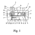
- Fig. 1 shows in a schematic sectional view - for illustration purposes not in scale - a dispensing device 1 according to the present invention.
- the dispensing device 1 is an active device, in particular gas powered.
- the dispensing device 1 is a preferably oral or nasal inhaler, in particular a dry powder inhaler, for a user, respectively the patient (not shown).
- the dispensing device 1 may be used for dispensing any formulation 2 as defined in the introductory part of the description.
- a medical formulation 2 or a formulation 2 for inhalation will be used.
- the formulation 2 preferably contains or consists of at least one drug.
- a spray 3 is generated as indicated in Fig. 1.
- the spray 3 includes fine particles (solid and/or liquid) and preferably has the desired spray plume characteristics.
- the formulation 2 may be a liquid, in particular a solution, a suspension or any mixture thereof, i.e. a so-called suslution.
- a suslution may be used.
- the principle of the suslution is based on that different drugs may be combined in one formulation simultaneously as a solution and as a suspension.
- EP 1 087 750 Al which is incorporated herein as additional disclosure in this respect.
- the formulation is a powder.
- the powder may be a pure drug or a mixture of at least two drugs.
- the powder may contain at least one other material, in particular a drug carrier such as lactose.
- a drug carrier such as lactose.
- the mean diameter of the powder particles is about 2 to 7 ⁇ m, in particular 6 ⁇ m or less. This applies in particular if the powder does not contain any drug carrier such as lactose.
- the powder 2 may have a particle size of 20 to 300 ⁇ m, in particular about 30 to 60 ⁇ m,
- the de-agglomeration which will be described later in more detail, may result even in this case in a spray 3 with a smaller particle size, e.g. of about 10 ⁇ m or less.
- the drug may be separated from the drug carrier during de-agglomeration so that primarily the drug will be inhaled due to its small particle size of about 2 to 6 ⁇ m and the larger drug carrier will be swallowed when using the dispensing device as an inhaler.
- breaking or opening of the drug carrier is possible during de-agglomeration.
- the diameters mentioned above and below may be understood as mass medium aerodynamic diameters and/or may apply to the particle size or a fraction of the particles of the spray 3.
- the dispensing device 1 is adapted to receive or comprises a storage device 4 for storing preferably multiple and pre-metered doses of the formulation 2.
- the storage device 4 may be integrated into the dispensing device 1 or form part of the dispensing device 1. Alternatively, the storage device 4 may be a separate part that can be inserted or connected with the dispensing device 1 and optionally replaced.
- the storage device 4 comprises a carrier 5 with at least one insert 6, preferably multiple inserts 6.
- the carrier 5 may comprises 20 to 100, preferably 30 to 60 inserts 6.
- Each insert 6 contains preferably one pre-metered dose of the formulation 2.
- each insert 6 may also contain more than the formulation 2, i.e. different formulation 2.
- different inserts 6 may contain different formulations.
- "different" means in particular that the formulations 2 differ in at least one of the composition, the drug, the dose or amount, the concentration, and consistance of the formulation 2, e. g. liquid or dry or powder 5.
- the carrier 5 comprises multiple cavities 7 for receiving the inserts 6.
- each insert 6 is located in a separate cavity 7.
- the cavities 7 are separate from each other and, in particular, sealed against each other.
- each cavity 7 comprises two preferably opposed openings 8.
- the openings 8 are covered by respective sealings 9 which are preferably formed by foils on opposite sides of the carrier 5, in particular metallic foils, plastic foils, multi-layer arrangements or the like.
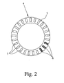
- Fig. 2 shows the storage device 4 with the carrier 5, wherein the top sealing 9 and some inserts 6 are omitted.
- the carrier 5 is ring-like and the cavities 7 extend at least substantially in axial direction.
- the cavities 7 are distributed around the perimeter of or along the carrier 5, preferably equally spaced to the adjacent cavities 7.
- the carrier 5 may be a molded element, a ring, a stripe, a cartridge, a blister or a container.
- the carrier 5 is rigid or at least essentially stiff.
- the carrier 5 is made of foil, plastics, ceramics and/or composite material, in particular of thermoplastics or thermoplastic elastomers and for sealings of elastomers or silicone.
- Each cavity 7 preferably forms a guide for the associated insert 6, in particular so that the insert 6 can be moved in at least one direction at least partially out of the cavity 7.
- Fig. 1 shows a situation, wherein the insert 6 on the left side has already been pushed at least partially out of its associated cavity 7 and/or through a respective sealing 9 of its associated cavity 7 for opening the sealing 9.
- the insert 6 shown on the right side of Fig. 1 is still within its closed and sealed cavity 7.
- Each insert 6 is preferably produced separately from the carrier 5 and, then, inserted into its respective cavity 7.
- each insert 6 is made of foil, plastics, ceramics and/or composite material, in particular of thermoplastics or thermoplastic elastomers and for sealings of elastomers or silicone.
- the carrier 5 and/or the inserts 6 are made of at least one of the following materials or any mixture or blend thereof:
- ABS acrylonitril-butadiene-styrene copolymer
- SAN styrene-acrylonitril-copolymer
- PBT polybutylene terephthalate
- PC polycarbonate
- CA cellulosic acetate
- EVA ethylene vinylacetate copolymer
- PA polyamide
- PE polyethylene
- PP polypropylene
- PMMA polymethylmethacrylate
- POM polyoxymethylene, polyacetal
- PPS polyphenylene sulfide
- PS polystyrene
- PBTP polybutylene terephthalate
- TPU thermoplastic polyurethane
- LCP liquid crystal polymers
- PHCS polypyrrol or polythiophene
- PPA polyphthalamide
- PSU polysulfone
- PTFE polytetrafluorethylene
- PUR polyurethane
- Each insert 6 may form a preferably block-like unit and be rigid. Alternatively, the inserts 6 may be flexible. In particular, each insert 6 may be a unitary unit or consists of multiple elements. Each insert 6 may be a molded element, a cartridge, a blister, a capsule, a container or the like.
- all inserts 6 are identical.
- the (all or some) inserts 6 are different.
- two or more groups of different inserts 6 can be provided. It is possible that one group has a different dose or different formulation 2 than the other group.
- the inserts 6 of the different groups could be arranged alternately one after the other so that a patient or user may use for example each morning an insert 6 of one group and each evening an insert 6 of the other group.
- Each insert 6 comprises a storage cavity 10 for a single dose of the formulation 2.
- the schematic sectional view according to Fig. 3 and schematic sectional view according to Fig. 4 along line IV-IV of Fig. 3 show one preferred embodiment of the insert 6.
- the insert 6 comprises a storage chamber 10 for the formulation 2.
- the storage chamber 10 is preferably formed in a molded base member 11 of the insert 6.
- the insert 6 / base member 11 further comprises a duct 12 or the like for discharging the formulation 2 during the dispensing operation.
- the formulation 2 is dispensed through the duct 12 during the dispensing operation, in particular for de-agglomerating the powder and/or forming the spray 3.
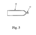
- the duct 12 can comprise a nozzle (restriction) 13 preferably at the outlet, as shown in the schematic longitudinal sectional view according to Fig. 5.
- nozzle 13 or any other suitable nozzle arrangement could be used instead of or in any other combination with duct 12.
- the duct 12 / nozzle 13 is formed by the base member 11, in particular by a recess, grove or the like in the base member 11 and by an associated cover member 14 as shown in Fig. 4.
- the duct 12 forms a channel from the storage chamber 10 to an outlet 15 of the insert 6 for discharging the formulation 2 as spray 3 as shown in Fig. 1.
- the insert 6 comprises preferably an inlet for supplying pressurized gas into the storage chamber 10 to force the formulation 2 through the duct 12 / nozzle 13 and to dispense the formulation 2 as spray 3.
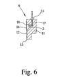
- the inlet is preferably designed as a tube-like recess or blind bore 16 formed in the base member 11.
- the recess 16 is not directly connected to the storage chamber 10, but separated by an intermediate wall. This wall can be penetrated e.g. by a piercing element 17 such as a needle as shown schematically in Fig. 6 or by any other suitable opening and/or supply means, in particular when the respective insert 6 is connected to a gas supply as explained in the following.
- the expression "piercing element 17" preferably covers also all other suitable types of means for opening the carrier 5, a cavity 7 and/or an insert 6 and/or for directly or indirectly supplying gas to an insert 6 or its respective storage chamber 10.
- the dispensing device 1 uses pressurized gas to force the formulation 2 through the duct 12 / nozzle 13 to de-agglomerate the powder and/or to generate the spray 3 with fine particles.
- the dispensing device 1 comprises a means for providing pressurized gas, in the present embodiment an air pump 18 which can preferably be actuated or operated manually as indicated by handle or actuator 19.
- the air pump 18 comprises or is formed by a bellows. But, it could be also a piston-cylinder-arrangement.
- the means for providing pressurized gas can be e.g. a capsule, container or the like containing pressurized or liquefied gas for powering the dispensing device 1, i.e. dispensing the formulation 2 as desired.
- the air pump 18 may provide a gas pressure of less than 300 kPa, in particular about 50 to 200 kPa. This is preferably sufficient for operating the dispensing device 1. If liquefied gas or a container with pressurized gas is used, the gas pressures might range from 100 kPa to about 700 kPa. Then, the pressure may be reduced or throttled to the preferred pressure range before supplying the gas to the storage device 4, in particular the storage chamber 10 of the respective insert 6.
- all pressure values mentioned in the present description are gauge pressures, i.e. pressure differences. All pressure values relate to the pressure in a gas storage such as a container with pressurized or liquefied gas or provided by air pump 18 or relate to the pressures acting in the chamber 10 and/or in the duct 12.
- Fig. 1 shows that the dispensing device 1 comprises a mechanism 20 for connecting the inserts 6 individually to the gas supply, in particular to the air pump 18.
- the mechanism 20 comprises preferably the piercing element 17 or any other suitable connecting element.
- the mechanism 20 is associated to a first (lower) housing member 21 of the dispensing device 1.
- the dispensing device 1 comprises further a second (upper) housing member 22 which may support the storage device 4 / carrier 5.
- the first and second housing members 21, 22 can be moved relatively to each other, in particular in axial direction with respect to the rotational axis of the carrier 5 or parallel to the orientation of the cavities 7. This relative movement enables the mechanism 20, in particular its piercing element 17, to connect or penetrate the respective insert 6 adjacent to the mechanism 20.
- the relative movement results in a first phase in that the piercing element 17 penetrates the sealing 9 and, then, is inserted into the recess 16 and through the end wall into the storage chamber 10 and, thus, connects the respective insert 6 to the gas supply.
- a shoulder or abutment 23 (better shown schematically in Fig. 6) abuts at the insert 6 so that the insert 6 is pushed through the other opening 8 and through the respective sealing 9 at least partially out of its cavity 7.
- Fig. 1 This final situation is shown in Fig. 1.
- the relative movement of the first and second housing members 21, 22 can also actuate the air pump 18 or open any other gas storage.
- the air pump 18 may be actuated separately by means of the actuator 19.
- the gas is supplied under pressure to the storage chamber 10 via the piercing element 17 or any other suitable supply element.
- the gas (air) generates a respective flow in the storage chamber 10 to force the complete dose through the duct 12.
- the powder will be discharged - in particular forced through the duct 12 - with a comparatively low gas pressure (preferably less than 300 kPa, in particular about 50 to 200 kPa).
- a comparatively low gas pressure preferably less than 300 kPa, in particular about 50 to 200 kPa.
- the storage chamber 10 forms a mixing chamber for mixing the gas with the powder.
- the chamber 10 is preferably designed such that the gas can generate swirls or eddies for better mixing the powder with the gas.
- the chamber 10 is substantially circular in cross section, in particular cylindrical. However, other shapes are also possible.
- the chamber 10 is formed with no sharp edges, corners or the like, but has a smooth contour so that the gas can sweep all chamber surfaces to prevent powder accumulating on said surfaces and to ensure or allow complete discharge of the powder.
- the gas inlet formed by the piercing element 17 or any other supply element is located opposite to the outlet, i.e. duct 12 and/or nozzle 13, with regard to the axial or outlet direction.
- the storage device 4 may comprise only one insert 6 with one storage chamber 10 for a single dose or with multiple storage chambers 10 with different formulations 2, in this case the storage device 4 is for single dose or use only, but comprises preferably multiple inserts 6 and, thus, contain multiple doses of the formulation 2, which can be dispensed subsequently.
- the spray 3 is preferably directly generated by the respective insert 6 or its duct 12 / nozzle 13 and outputted into a mouthpiece 24 of the dispensing device 1 as shown in Fig. 1 for inhalation by a patient or user (not shown).
- the piercing element 17 will be withdrawn from the connected insert 6, in particular due to an opposite relative movement of the first and second housing members 21 and 22.
- the carrier 5 will be indexed one step further or to the next insert 6, in particular rotated my means of an indexing or transport mechanism (not shown). This mechanism is preferably operated by the relative movement of the first and second housing members 21, 22 or by actuating an other actuator, by opening a cap of the dispensing device 1 or the like.
- the carrier 5 is preferably rotateable around axis "A" shown in Fig. 1 and supported by a respective holder 25, preferably connected to the second housing member 21.
- the dispensing device 1 can be opened and the storage device 4 / carrier 5 can be inserted or replaced.
- first and second housing member 21, 22 may be pivoted relatively to each other alternatively or additionally to the relative axial movement described above. Then, the mechanism 20 may be adapted respectively in order to provide the desired function, in particular the axial connection and displacement of the respective insert 6.
- the inserts 6 are preferably open, i.e. not sealed. Instead, experiments have shown that sealing of the carrier 5 / the cavity 7 is sufficient.
- the duct 12 / nozzle 13 is preferably so small that the formulation 2 is not discharged, even with opened sealing 9 and during strong shaking of the dispensing device 1 / storage device 4.
- inserts 6 and cavities 7 are preferably adapted to each other such that the sealings 9 contact the end faces of the inserts 6 and, thus, cover the outlets 15, This may further prevent that any formulation 2 discipates through the duct 12 / outlet 15 before the desired dispensing.
- the cross sections of the inserts 6 and the cavities 7 are preferably polygonal, in particular rectangular, in order to avoid that the inserts 6 may pivot within the cavities 7.
- the inserts 6 may also be cylindrically and/or can rotate within the cavities 7. This may facilitate insertion of the inserts 6 into the cavities 7 during production.
- the duct 12 has a flat (inner) cross section.
- Fig. 7a to 7c show potential cross sections of the duct 12.
- Fig. 7a shows a substantially rectangular cross section.
- Fig. 7b shows a flat cross section with two opposite straight sides connected by two curved portions.
- Fig. 7c shows an oval or elliptical cross section.
- a cross section is considered to be flat when the ratio of the largest side d1 to the smallest side d2 of the cross section is at least 2.0. Preferably, the ratio is between 3 to 50 and in particular about 5 to 70. It is pointed out that the cross sections shown in Fig. 7 are not in scale.
- the largest side d1 is preferably between 0.5 to 5 mm, in particular 1 to 3 mm. Most preferably, the ratio of the largest side d1 to the (desired) fine particle size (mass mean diameter of the powder particles or drug particles of the spray 3) is less than 500, preferably less than 300, in particular about 30 to 300.
- the smallest side d2 is preferably between 0.05 to 0.5 mm, in particular about 0.07 to 0.25 mm. Most preferably, the ratio of the smallest side d2 to the mass mean (desired) fine particle size (mass mean diameter of the powder particles / drug particles of the spray 3) is less than 50, preferably less than 30, in particular about 3 to 20.
- the length of the duct 12 means the length with the flat cross section.
- the duct 12 can have a larger length, i.e. further portions with another cross sectional shape and/or with a larger cross sectional area so that the influence of these other portions is low on the mixture of gas and powder in comparison to the portion of the duct 12 with the flat cross section.
- the cross section area and/or the shape of the flat cross section may vary over the length of the duct 12 (the portion with the flat cross section).
- the cross sectional area of the duct 12 tapers from the inlet to the outlet or vice versa.
- the duct 12 comprises at least one portion of flat cross section with constant cross section area, i.e. constant diameter and/or shape.
- the length of the duct 12 - i.e. the portion with flat cross section - may be in the range of 3 mm to 80 mm, in particular 5 to 15 mm.
- the duct length is adapted to the mean hydraulic diameter of the duct 12 such that the ratio of the length of the duct 12 to the mean hydraulic diameter is at least 5, in particular about 10, preferably 20 to 60, or more, wherein the hydraulic diameter is defined as the ratio of four cross sectional areas over the duct perimeter.
- the diameter of the preferably circular or cylindrical or conical chambers 10 depend on the volume or mass of the respective dose of the formulation 2.
- a single dose may have e.g. 1 to 2 mg (pure drug without carrier) or 2 to 10 mg (blend of drug with carrier, in particular lactose).
- the range of the diameter is preferably 1.5 to 2.5 mm.
- the range of the diameter is preferably between 2 and 5 mm.
- the cross section of the duct 12 varies in a similar manner.
- the smallest side d2 is about 0.07 to 0.1 mm in the first case and about 0.15 to 0.25 mm in the second case.
- the larger (inner) side d1 does not depend so strongly on the powder or spray particle size.
- it is in the range of about 1 to 2 mm in the first case and 1 to 3 mm in the second case.
- the mean hydraulic diameter of the duct 12 is preferably less than 1 mm, in particular 0.1 mm to 0.6 mm.
- the duct 12 is molded and/or formed by a flat groove with a cover.
- the dispensing device 1 may comprise a common duct 12 / nozzle 13 for dispensing the dose of the formulation 2 from one insert 6 after the other.
- the insert 6 may be pressed with its outlet 15 against this common duct 12 / nozzle 13 (not shown) which may be arranged e.g. above the elevated insert 6 shown in Fig. 1, i.e. within or below the mouthpiece 24.
- Each insert may comprise multiple ducts 12 for dispensing simultaneously one dose, in particular for increasing the total mass flow or output so that a desired dose can be discharged or dispensed in a sufficiently short time as desired and/or required.
- Fig. 8 shows another embodiment of the insert 6 in a sectional view similar to Fig. 3.
- the insert 6 comprises two ducts 12 associated or connected to the same storage chamber 10.
- Fig. 9 shows in a schematic sectional view another insert 6 with a means for slowing down the velocity which forms a multiple jet impinging means 18.
- the means 18 forms multiple - at least two - jets P which impinge, i.e. hit each other as indicated in Fig. 9.
- the duct 12 divides into two sections 12a and 12b that are designed such that the openings or outlets 15 are inclined to each other so that the jets P ejecting from the portions 12a and 12b are inclined to each other and impinge.
- a flow divider 27 or any guiding means can be located in the flow path to form the at least two sections 12a and 12b of the duct 12 as shown in Fig. 9.
- cross sections of the duct sections 12a and 12b are preferably not flat, but can have any suitable cross sectional shape.
- the impinging angle ⁇ between the jets P is between 30° to 180°, preferably at least 90° for powder, in particular about 90° to 150°.
- the impinging of the jets P results in a decrease of the velocity of the spray 3 and/or in a de-agglomeration of the powder or forming of small droplets and/or in separation of drug particles from a carrier and/or in better focusing of the spray 3.
- These effects depend on the impinging angle ⁇ .
- a larger impinging angle ⁇ tends to result in better effects.
- an impinging angle ⁇ of 90° and more is possible and preferred for powder.
- the duct 12 is preferably at least tangentially connected to the storage chamber 10 in the embodiment shown in Fig. 9.
- the duct 12 is connected at one axial end of the preferably cylindrical chamber 10, and the gas inlet is connected to the other axial end of the chamber 10.
- the gas inlet is connected also tangentially to the storage chamber 10, such that swirls are generated when entering the gas with a swirl direction supporting discharge of the mixture of gas and formulation 2 through the duct 12 which connects tangentially to the rotational direction of the swirl.
- the present invention in particular the dispensing device 1 and/or the storage device 4, can be used for dispensing one drug, a blend of drugs or at least two or three separate drugs.
- the separate drugs are stored in separate storage chambers 10 and, during the dispensing operation, the drugs are mixed either in a common mixing chamber or in their respective storage chambers 10 with the gas.
- the separate drugs can be discharged through a common duct 12 nozzle 13 or through separate ducts 12 nozzles 13.
- the separate drugs will be mixed after leaving the separate ducts 12 / nozzles 13 or in the mouthpiece 24 or in any other suitable (additional) mixing chamber. It is also possible to mix the separate drugs by impinging jets of the separate drugs.
- a common gas supply or means for pressurizing gas such as an air pump 18.
- Fig. 10 shows in a schematic sectional view another embodiment of the insert 6.
- Two different formulations 2' and 2" are contained in separate storage chambers 10' and 10", respectively. Gas can be supplied via a common inlet / recess 16 to the chambers 10' and 10", respectively.
- the formulations 2' and 2" can be dispensed and de-agglomerated by means of separate ducts 12' and 12" or (not shown) separate nozzles or the like.
- the jets P of the separate and different formulations 2' and 2" ejecting from the separate ducts 12' and 12" are preferably impinged for mixing the separate formulations 2' and 2" just when forming the spray 3 (not shown).
- the jet impinging means 26 mixes the separate formulations 2' and 2", but can also serve to slow down the propagation velocity of the spray 3 and/or to support de-agglomeration of powder formulations 2' and 2" or of separating the respective drugs from carriers.
- Fig. 9 and 10 are also suitable for impinging more than two jets P.
- multiple other arrangements with similar effects are possible.
- the duct 12 can also be used as a reservoir (storage chamber 10) for the formulation 2. In this case, the separate storage chamber 10 is not required. Then, the duct 12 is designed to enable sufficient mixing of the gas with the formulation 2 and sufficient de-agglomeration of the powder formulation 2.
- the spray 3 has a mean velocity (taken 20 cm from the outlet 15 or mouthpiece 24) of less than 2 m/s, in particular less than 1 m/s.
- the mean duration of the spray 3 is at least 0.2 or 0.3 s, in particular about 0.5 to 25.
- Fig. 11 shows another embodiment of the dispensing device 1.
- Fig. 11 shows another embodiment of the dispensing device 1.
- the previous explanation in particular the description with respect to the embodiment according to Fig. 1, applies in addition or in a similar manner.
- the cavities 7 are orientated in tangential or radial direction of the carrier 5. Consequently, the inserts 6 can be individually moved in tangential or radial direction, in particular outwardly, in order to open the respective outer sealing 9 for dispensing the respective dose of the formulation 2 as indicated in Fig. 11. Accordingly, the mechanism 20 operates in a radial direction for connecting the inserts 6 individually to a gas supply and for pushing the inserts 6 individually at least partially out of the respective cavity 7 and/or through the respective sealing 9. This radial movement allows a very compact design of the dispensing device 1, in particular in axial direction.
- the mouthpiece 24 and the dispensing direction extents in radial or tangential direction as shown in Fig. 11.
- the dispensing device 1 comprises a lever or handle (not shown) for manual actuation in order to index the carrier 5 one step further, i.e. to the next insert 6, and/or to operate the mechanism 20, preferably to connect the respective insert 6 to the gas supply or to move / push the respective insert 6 and open the respective sealing for dispensing the respective dose of the formulation 2.
- a lever or handle for manual actuation in order to index the carrier 5 one step further, i.e. to the next insert 6, and/or to operate the mechanism 20, preferably to connect the respective insert 6 to the gas supply or to move / push the respective insert 6 and open the respective sealing for dispensing the respective dose of the formulation 2.
- Fig. 12 shows another embodiment of the storage device 4 / carrier 5.
- the carrier 5 is like a band or stripe, i.e. preferably essentially linear or straight. This facilitates production of the carrier 5 because lamination of the sealings 9 on the opposite straight sides of the carrier 5 is simple.
- the sealings 9, such as foil are laminated to the carrier 5, e.g. by hot sealing or the like.
- the carrier 5 is preferably rigid.
- the carrier 5 is preferably flexible and can be bent to a preferably ring-like arrangement and connected - e.g. by glueing - with its ends to a closed belt or a loop.
- the inserts 6 are preferably rigid, in particular if formed by molded elements or the like. However, the inserts 6 may be alternatively flexible, in particular if formed by blisters or the like.
- the arrow P indicates the possible movement of one of the inserts 6 for opening the respective sealing 9.
- the inserts 6 may be formed as capsules or the like without any duct 12, nozzle 13 or the like. Instead, each insert 6 is connected individually to a gas supply and to a common outlet arrangement, such as a duct 12, nozzle 13 or the like for dispensing the respective dose of the formulation 2.
- a secondary packaging may be used for packing and protecting the storage device 4 / carrier 5, in particular for storage purposes before inserting the storage device 4 / carrier 5 into the dispensing device 1. Additionally the whole device 1 including storage device 4 / carrier 5 may be stored in a secondary water vapour proof packaging.
- the dispensing devise 1 may be breath activated, in particular wherein the formulation 2 is only released after the patient's or user's inhalation rate has reached a predetermined level, preferably by the use of a pressure sensitive means, such as a bursting element, membrane or valve, or any other mechanism.
- a pressure sensitive means such as a bursting element, membrane or valve, or any other mechanism.
- Example 1 A blend of 90.0 % by weight of lactose 200, of 9.7 % by weight of fine lactose, and of 0.3 % by weight of Tiotropium was used.
- the mean particle diameter of lactose 200 was about 45 ⁇ m, of fine lactose about 4 ⁇ m and of Tiotropium about 4 ⁇ m.
- About 5.5 mg of the blend was positioned as powder in the storage 10 which had a substantially cylindrical shape with a diameter of 3 mm and an axial length of 3 mm. 5 ml of compressed air was supplied into the chamber 10 with a gauge pressure of about 100 kPa.
- the powder was dispensed via duct 12 of substantially rectangular cross section having a smallest side of about 0.18 mm and a largest side of about 1.5 mm.
- the duct 12 divided into two duct sections 12a and 12b (in particular as shown in Fig. 9), wherein each section had a substantially rectangular cross section with a smallest side of about 0.18 mm and the largest side of about 0.75 mm.
- the total length of the duct 12 including the sections 12a, 12b was about 8 mm.
- the result was that 100 % of the metered mass, i.e. all powder in chamber 10, was dispensed. Approximately 50% of the Tiotropium was measured as fine fraction on an Anderson Cascade Impactor at both 30 and 60 1/min.
- Example 2 About 1.5 mg of Fenoterol with a mean particle diameter of 4 ⁇ m was positioned as powder in the storage chamber 10 which had a substantially cylindrical shape with a diameter of 2 mm and an axial length of 2 mm. 5 ml of compressed air was supplied via the gas inlet having an inlet orifice of 0.5 mm into the chamber 10 with a gauge pressure of about 150 kPa. The powder was dispensed via a duct 12 of substantially rectangular cross section having a smallest side of 0.075 mm and a largest side of 1.5 mm. The duct 12 divided into two duct sections 12a and 12b (in particular as shown in fig.
- each section had a substantially rectangular cross section with a smallest side of about 0.075 mm and the largest side of about 0.75 mm.
- the total length of the channel including the sections 12a, 12b was about 8 mm. The result was that 100 % of the metered mass, i.e. all powder in chamber 10, was dispensed. Approximately 45% of the Fenoterol was measured as fine fraction on an Anderson Cascade Impactor at both 30 and 60 l/min.
- the formulation may contain or consist of additional pharmacologically active substances or mixtures of substances, preferably selected from those groups:
- Anticholinergica preferably selected from the group consisting of tiotropium, tiotropiumbromide, oxitropiumbromide, flutropiumbromide, ipratropiumbromide, glycopyrroniumsalts, trospiumchloride, tolterodin, 2,2-diphenylpropionacidtropenolester-methobromide, 2,2-diphenylpropionacidscopinester-methobromide, 2-fluoro-2,2-diphenylacidicacidscopinester-methobromide, 2-fluoro-2,2-diphenylacidicacidtropenolester-methobromide, 3,3',4,4'-tetrafluorbenzilacidtropenolester-methobromide, 3,3',4,4'-tetrafluorbenzilacidtropenolester-methobromide, 3,3',4,4'-tetrafluorbenzilacidtropeno
- Beta-sympathomimetica preferably selected from the group consisting of albuterol, bambuterol, bitolterol, broxaterol, carbuterol, clenbuterol, fenoterol, formoterol, hexoprenaline,ibuterol, indacterol, isoetharine, isoprenaline, levosalbutamol, mabuterol, meluadrine, metaproterenol, orciprenaline, pirbuterol, procaterol, reproterol, rimiterol, ritodrine, salmeterol, salmefamol, soterenot, sulphonterol, tiaramide, terbutaline, tolubuterol, CHF-1035, HOKU-81, KUL-1248, 3-(4- ⁇ 6-[2-hydroxy-2-(4-hydroxy-3-hydroxymethylphenyl)-ethylamino]-hex-yloxy ⁇ -
- Steroids preferably selected from the group consisting of prednisolone, prednisone, butixocortpropionate, RPR-106541, flunisolide, beclomethasone, triamcinolone, budesonide, fluticasone, mometasone, ciclesonide, rofleponide, ST-126, dexamethasone, 6 ⁇ ,9 ⁇ -difluoro-17 ⁇ -[(2-furanylcarbonyl)oxy]-11 ⁇ -hydroxy-16 ⁇ -methyl-3-oxo-androsta-1,4-dien-17 ⁇ -carbothionacid (S)-fluoromethylester, 6 ⁇ ,9 ⁇ -difluoro-11 ⁇ -hydroxy-16 ⁇ -methyl-3-oxo-17 ⁇ -propionyloxy-androsta-1,4-dien-17 ⁇ -carbothionacid (S)-(2-oxo-tetrahydro-furan-3S-yl) ester and etiprednol-
- PDE IV-inhibitor preferably selected from the group consisting of enprofyllin, theophyllin, roflumilast, ariflo (cilomilast), CP-325,366, BY343, D-4396 (Sch-351591), AWD-12-281 (GW-842470), N-(3,5-Dichloro-1-oxo-pyridin-4-yl)-4-difluoromethoxy-3-cyclopropylmethoxybenzamide, NCS-613, pumafentine, (-)p-[(4 a R*,10 b S*)-9-ethoxy-1,2,3,4,4a,10b-hexahydro-8-methoxy-2-methylbenzo[s][1,6]naphthyridin-6-yl]-N,N-diisopropylbenzamide, (R)-(+)-1-(4-bromobenzyl)-4-[(3-cyclopentyl
- LTD4-antagonist preferably selected from the group consisting of montelukast, 1-(((R)-(3-(2-(6,7-difluoro-2-quinolinyl)ethenyl)phenyl)-3-(2-(2-hydroxy-2-propyl)phenyl)thio)methylcyclopropan-acidicacid, 1-(((1(R)-3(3-(2-(2,3-dichlorothieno[3,2-b]pyridin-5-yl)-(E)-ethenyl)phenyl)-3-(2-(1-hydroxy-1-methylethyl)phenyl)propyl)thio)methyl)cyclopropanacidicacid, pranlukast, zafirlukast, [2-[[2-(4-tert-butyl-2-thiazolyl)-5-benzofuranyl]-oxymethyl]phenyl]acidicacid, MCC-847 (ZD-3523), MN-001,
- the compound could be from the group of betamimetika, antiallergika, derivates of ergotalcaloids, triptane, CGRP-antagonists, phosphodiesterase-V-inhibitores, optionally in the form of the racemates, the enantiomers, the diastereomers and optionally the pharmacologically acceptable acid addition salts and the hydrates therof.
- the pharmacologically acceptable acid addition salts could be from the group of hydrochloride, hydrobromide, hydroiodide, hydrosulfate, hydrophosphate, hydromethansulfonate, hydronitrate, hydromaleate, hydroacetate, hydrobenzoate, hydrocitrate, hydrofumarate, hydrotartrate, hydrooxalate, hydrosuccinate, hydrobenzoate und hydro-p-toluolsulfonate, preferably hydrochloride, hydrobromide, hydrosulfate, hydrophosphate, hydrofumarate and hydromethansulfonate.
- inhalable macromolecules can be used as pharmacologically active substances, as disclosed in EP 1 003 478 .
- compositions and mixtures of pharmaceuticals with the above named pharmacologically active substances can be used, as well as their pharmacologically active salts, esters and combinations of the pharmacologically active substances, salts and esters.
Landscapes
- Health & Medical Sciences (AREA)
- Engineering & Computer Science (AREA)
- Anesthesiology (AREA)
- Biomedical Technology (AREA)
- Heart & Thoracic Surgery (AREA)
- Hematology (AREA)
- Life Sciences & Earth Sciences (AREA)
- Animal Behavior & Ethology (AREA)
- General Health & Medical Sciences (AREA)
- Public Health (AREA)
- Veterinary Medicine (AREA)
- Bioinformatics & Cheminformatics (AREA)
- Pulmonology (AREA)
- Medicinal Preparation (AREA)
- Containers And Packaging Bodies Having A Special Means To Remove Contents (AREA)
- Medical Preparation Storing Or Oral Administration Devices (AREA)
- Infusion, Injection, And Reservoir Apparatuses (AREA)
- Pharmaceuticals Containing Other Organic And Inorganic Compounds (AREA)
- Coating Apparatus (AREA)
Abstract
A dispensing device, a storage device and a method for dispensing a medical formulation are proposed. Multiple doses of the formulation are stored in a carrier having multiple inserts, each insert containing a single dose. Preferably, each insert comprises at least one duct or nozzle for dispensing the respective dose. Each insert is located in a separate and sealed cavity in the carrier. The cavities can be individually opened for dispensing the respective dose from the respective insert.
Description
- The present invention relates to a dispensing device for dispensing a preferably medical formulation, in particular containing or consisting of a drug or mixture of drugs, according to the preamble of
claim 1, to a storage device for a preferably medical formulation, in particular containing or consisting of a drug or mixture of drugs, according to the preamble of claim 30, and to a method for dispensing a preferably medical formulation, in particular containing or consisting of a drug or mixture of drugs, according to the preamble of claim 50. - Drugs delivered through dispensing devices, in particular inhalers, are intended to optimally target specific sites in the pulmonary system. These sites include the nasal passages, the throat, and various locations within the lungs, such as the bronchi, bronchioles and alveolar regions. The ability to deliver drugs to a target area depends inter alia on the aerodynamic sizes of the particles or droplets. As currently believed to be understood, particles having an aerodynamic diameter of less than 2 µm are considered to be potentially optimal for deposition in the alveolar region of the lung. Particles that have an aerodynamic diameter of between 2 and approximately 5 µm may be more suitable for delivery to the bronchiole or bronchi regions. Particles with an aerodynamic size range greater than 6 µm, and more preferably 10 µm, are typically suitable for delivery to the laryngeal region, throat or nasal passages.
- In most cases, it is desired to achieve a high inhalable fraction and a high delivery efficiency, i.e. the fraction of the initial dose of drug that reaches the desired region, in particular in the lung. This depends on various factors, in particular on the characteristics of the generated spray plume, such as propagation velocity of the plume, particle size and its distribution, fraction of small particles, fraction of gas or the like. In the present invention, the desired spray plume characteristics include preferably a small particle size, a high fraction of drug particles with a diameter of 6 µm or less, a low propagation velocity and/or a long duration of spray generation and possible inhalation.
- The present invention relates to the dispensing of a preferably medical formulation. The term "formulation" relates in particular to powder, but may include or relate to liquid as well. Consequently, the fine "particles" may be either solid or liquid. The term "liquid" has to be understood preferably in a broad sense covering inter alia solutions, suspensions, suslutions, mixtures thereof or the like. More particularly, the present invention relates to the dispensing of formulations for inhalation, such as medical formulations containing or consisting of at least one drug.
- In the following, the description will focus mainly on powder formulations. However, the same applies for liquid formulations.
- In particular, the present invention is concerned with dry powder inhalers for the delivery of drugs to the lungs. Many dry powder inhalers are on the market or have been proposed. There are two main types, namely the passive ones and the active ones. In passive inhalers all the energy required for de-agglomerating the powder and transferring the powder to the lungs is provided by the breathing of a user, respectively the patient. In active inhalers there is an additional source of energy to help to de-agglomerate the powder.
- Most powder inhalers are of the passive type where the powder is inhaled by the patient without the aid of an additional energy source. The problem with passive inhalers is that the inhalable fraction, or the proportion of powder that actually enters the lungs, is largely dependent on the breathing of the patient. The de-agglomeration of the powder and hence the inhalable fraction is a function of the flow rate of inhaled air through the device and, therefore, varies greatly from patient to patient
- Dry powder inhalers are subdivided into single dose and multi-dose devices or inhalers. Multi-dose inhalers are further subdivided into pre-metered types where the doses are stored individually and into metering inhalers where each powder dose is metered in the device.
- Multi dose pre-metered inhalers have the advantage that the single doses are metered under strict factory conditions and the powder can quite easily be isolated from the atmosphere. In many applications the active drug powder is mixed with a carrier such as lactose which tends to absorb humidity from the atmosphere which makes it stick together and difficult to de-agglomerate.
- The present invention relates in particular to an active, gas (preferably air) powered, pre-metered multi-dose dispensing device for dispensing a formulation containing or consisting of a drug, such as a dry powder inhaler.
-
US 4,627,432 A discloses a device for administering medicaments to patients, namely an inhaler. The inhaler comprises a disk-like blister pack having a plurality of blister pockets arranged in a circle. Each blister pocket contains a dose of the powder. A plunger can open a blister pocket. When a blister is opened, the medicament can be withdrawn by a patient inhaling through a mouthpiece. - It is difficult to empty the respective blister pocket completely during a dispensing operation. Incomplete emptying results in decreased delivery efficiency. Some powder may be lost in the inhaler and not dispensed because the known solutions require relatively long paths for the powder until the powder reaches a nozzle and is actually dispensed. This might reduce the delivery efficiency further in addition, de-agglomeration of the powder is difficult and the powder may block an outlet nozzle that is used for dispensing multiple doses one after the other.
- Object of the present invention is to provide an improved dispensing device, storage device and method for dispensing a preferably medical formulation, in particular wherein a high delivery efficiency, a good sealing and/or the desired spray plume characteristics can be achieved.
- The above object is achieved by a dispensing device according to
claim 1, by a storage device according to claim 30 or by a method according to claim 50. Preferred embodiments are subject of the subclaims. - One aspect of the present invention is to provide a carrier with multiple inserts, wherein each insert contains one dose of the formulation that shall be dispensed. Thus, it is possible to seal the carrier in an optimized manner, i.e. very effectively. Further, the inserts may store the formulation in an optimized manner so that easy, effective and complete delivery of the respective dose of the formulation can be achieved.
- According to a preferred embodiment, the inserts may be respectively used to open an associated sealing, in particular by pushing the respective insert through the associated sealing of the carrier or at lest partially out of a cavity of the carrier containing the respective insert.
- According to another embodiment, each insert comprises at least one duct or nozzle for dispensing the respective dose of the formulation and generating the desired spray with fine particles.
- Further aspects, advantages and features of the present invention will be apparent from the claims and following detailed description of preferred embodiments. In the drawings show:
- Fig. 1
- a schematic sectional view of a dispensing device with a storage device according to one embodiment of the present invention during dispensing;
- Fig. 2
- a top view of the storage device with multiple inserts;
- Fig. 3
- a schematic sectional view of an insert;
- Fig. 4
- another schematic sectional view of the insert;
- Fig. 5
- a schematic longitudinal sectional view of a duct with a nozzle;
- Fig. 6
- a schematic sectional view similar to Fig. 4 with an inserted piercing element;
- Fig. 7a - 7c
- cross sectional views of ducts of the insert with different cross sections;
- Fig. 8
- a schematic sectional view of another insert;
- Fig. 9
- a schematic sectional view of a further insert;
- Fig. 10
- a schematic sectional view of a still further insert;
- Fig. 11
- a schematic sectional view of a dispensing device with a storage device according to another embodiment during dispensing; and
- Fig. 12
- a schematic view of another storage device.
- In the Fig., the same reference signs are used for same or similar components, wherein same or similar characteristics, features or advantages are or can be realized or achieved even if a repeated discussion is omitted. Further, the features and aspects of the different embodiments can be combined in any desired manner and/or used for other dispensing devices or methods for dispensing in particular medical formulations for inhalation.
- Fig. 1 shows in a schematic sectional view - for illustration purposes not in scale - a
dispensing device 1 according to the present invention. Thedispensing device 1 is an active device, in particular gas powered. Preferably, thedispensing device 1 is a preferably oral or nasal inhaler, in particular a dry powder inhaler, for a user, respectively the patient (not shown). - The
dispensing device 1 may be used for dispensing anyformulation 2 as defined in the introductory part of the description. In particular, amedical formulation 2 or aformulation 2 for inhalation will be used. Theformulation 2 preferably contains or consists of at least one drug. When theformulation 2 is dispensed, aspray 3 is generated as indicated in Fig. 1. Thespray 3 includes fine particles (solid and/or liquid) and preferably has the desired spray plume characteristics. - The
formulation 2 may be a liquid, in particular a solution, a suspension or any mixture thereof, i.e. a so-called suslution. Preferably, when different drugs are dispensed simultaneously, a suslution may be used. The principle of the suslution is based on that different drugs may be combined in one formulation simultaneously as a solution and as a suspension. In this respect, reference is made toEP 1 087 750 - Preferably, the formulation is a powder. The powder may be a pure drug or a mixture of at least two drugs. In addition, the powder may contain at least one other material, in particular a drug carrier such as lactose. In the following, the description focuses on powder as
formulation 2. However, this applies in a similar manner if aliquid formulation 2 is used. - Preferably the mean diameter of the powder particles is about 2 to 7 µm, in particular 6 µm or less. This applies in particular if the powder does not contain any drug carrier such as lactose.
- If the powder contains a drug carrier, such as lactose, and at least one drug, the
powder 2 may have a particle size of 20 to 300 µm, in particular about 30 to 60 µm, However, the de-agglomeration, which will be described later in more detail, may result even in this case in aspray 3 with a smaller particle size, e.g. of about 10 µm or less. In particular, the drug may be separated from the drug carrier during de-agglomeration so that primarily the drug will be inhaled due to its small particle size of about 2 to 6 µm and the larger drug carrier will be swallowed when using the dispensing device as an inhaler. Alternatively or additionally, breaking or opening of the drug carrier is possible during de-agglomeration. - The diameters mentioned above and below may be understood as mass medium aerodynamic diameters and/or may apply to the particle size or a fraction of the particles of the
spray 3. - The
dispensing device 1 is adapted to receive or comprises astorage device 4 for storing preferably multiple and pre-metered doses of theformulation 2. Thestorage device 4 may be integrated into thedispensing device 1 or form part of thedispensing device 1. Alternatively, thestorage device 4 may be a separate part that can be inserted or connected with thedispensing device 1 and optionally replaced. - The
storage device 4 comprises acarrier 5 with at least oneinsert 6, preferablymultiple inserts 6. In particular, thecarrier 5 may comprises 20 to 100, preferably 30 to 60inserts 6. Eachinsert 6 contains preferably one pre-metered dose of theformulation 2. However, eachinsert 6 may also contain more than theformulation 2, i.e.different formulation 2. Additionally or alternatively,different inserts 6 may contain different formulations. In the present invention, "different" means in particular that theformulations 2 differ in at least one of the composition, the drug, the dose or amount, the concentration, and consistance of theformulation 2, e. g. liquid or dry orpowder 5. - The
carrier 5 comprisesmultiple cavities 7 for receiving theinserts 6. In particular, eachinsert 6 is located in aseparate cavity 7. - The
cavities 7 are separate from each other and, in particular, sealed against each other. - In the present embodiment, each
cavity 7 comprises two preferably opposedopenings 8. Before use, theopenings 8 are covered byrespective sealings 9 which are preferably formed by foils on opposite sides of thecarrier 5, in particular metallic foils, plastic foils, multi-layer arrangements or the like. - Fig. 2 shows the
storage device 4 with thecarrier 5, wherein thetop sealing 9 and someinserts 6 are omitted. In this embodiment, thecarrier 5 is ring-like and thecavities 7 extend at least substantially in axial direction. Thecavities 7 are distributed around the perimeter of or along thecarrier 5, preferably equally spaced to theadjacent cavities 7. - The
carrier 5 may be a molded element, a ring, a stripe, a cartridge, a blister or a container. Preferably, thecarrier 5 is rigid or at least essentially stiff. - Preferably, the
carrier 5 is made of foil, plastics, ceramics and/or composite material, in particular of thermoplastics or thermoplastic elastomers and for sealings of elastomers or silicone. - Each
cavity 7 preferably forms a guide for the associatedinsert 6, in particular so that theinsert 6 can be moved in at least one direction at least partially out of thecavity 7. - Fig. 1 shows a situation, wherein the
insert 6 on the left side has already been pushed at least partially out of its associatedcavity 7 and/or through arespective sealing 9 of its associatedcavity 7 for opening thesealing 9. Theinsert 6 shown on the right side of Fig. 1 is still within its closed and sealedcavity 7. - Each
insert 6 is preferably produced separately from thecarrier 5 and, then, inserted into itsrespective cavity 7. - Preferably, each
insert 6 is made of foil, plastics, ceramics and/or composite material, in particular of thermoplastics or thermoplastic elastomers and for sealings of elastomers or silicone. - According to a preferred embodiment, the
carrier 5 and/or theinserts 6 are made of at least one of the following materials or any mixture or blend thereof: - ABS (acrylonitril-butadiene-styrene copolymer); SAN (styrene-acrylonitril-copolymer); PBT (polybutylene terephthalate); PC (polycarbonate); CA (cellulosic acetate); EVA (ethylene vinylacetate copolymer); PA (polyamide); PE (polyethylene); PP (polypropylene); PMMA (polymethylmethacrylate); POM (polyoxymethylene, polyacetal); PPS (polyphenylene sulfide); PS (polystyrene); PBTP (polybutylene terephthalate); TPU (thermoplastic polyurethane); blend of PC and PBTP; blend of PC and ABS; LCP (liquid crystal polymers); PHCS (polypyrrol or polythiophene); PPA (polyphthalamide); PSU (polysulfone); PTFE (polytetrafluorethylene); PUR (polyurethane); SB (styrene-butadiene copolymer); PIB (polyisobutylene); PAN (peroxyacylnitrate); PET (polyethylene terephthalate); AMMA (acrylonitril-methymethacrylat copolymer); PAR (polyarylate); PEEK (polyetheretherketone).
- Each
insert 6 may form a preferably block-like unit and be rigid. Alternatively, theinserts 6 may be flexible. In particular, eachinsert 6 may be a unitary unit or consists of multiple elements. Eachinsert 6 may be a molded element, a cartridge, a blister, a capsule, a container or the like. - In the following, a preferred construction of one
insert 6 is explained. Preferably, allinserts 6 are identical. However, it is also possible that the (all or some) inserts 6 are different. For example, two or more groups ofdifferent inserts 6 can be provided. It is possible that one group has a different dose ordifferent formulation 2 than the other group. For example, theinserts 6 of the different groups could be arranged alternately one after the other so that a patient or user may use for example each morning aninsert 6 of one group and each evening aninsert 6 of the other group. - Each
insert 6 comprises astorage cavity 10 for a single dose of theformulation 2. The schematic sectional view according to Fig. 3 and schematic sectional view according to Fig. 4 along line IV-IV of Fig. 3 show one preferred embodiment of theinsert 6. Theinsert 6 comprises astorage chamber 10 for theformulation 2. In the present embodiment, thestorage chamber 10 is preferably formed in a moldedbase member 11 of theinsert 6. - The
insert 6 /base member 11 further comprises aduct 12 or the like for discharging theformulation 2 during the dispensing operation. Theformulation 2 is dispensed through theduct 12 during the dispensing operation, in particular for de-agglomerating the powder and/or forming thespray 3. - The
duct 12 can comprise a nozzle (restriction) 13 preferably at the outlet, as shown in the schematic longitudinal sectional view according to Fig. 5. Alternatively, thenozzle 13 or any other suitable nozzle arrangement could be used instead of or in any other combination withduct 12. - Preferably, the
duct 12 /nozzle 13 is formed by thebase member 11, in particular by a recess, grove or the like in thebase member 11 and by an associatedcover member 14 as shown in Fig. 4. In particular, theduct 12 forms a channel from thestorage chamber 10 to anoutlet 15 of theinsert 6 for discharging theformulation 2 asspray 3 as shown in Fig. 1. - The
insert 6 comprises preferably an inlet for supplying pressurized gas into thestorage chamber 10 to force theformulation 2 through theduct 12 /nozzle 13 and to dispense theformulation 2 asspray 3. In the present embodiment, the inlet is preferably designed as a tube-like recess orblind bore 16 formed in thebase member 11. Preferably, therecess 16 is not directly connected to thestorage chamber 10, but separated by an intermediate wall. This wall can be penetrated e.g. by a piercingelement 17 such as a needle as shown schematically in Fig. 6 or by any other suitable opening and/or supply means, in particular when therespective insert 6 is connected to a gas supply as explained in the following. In the present invention, the expression "piercingelement 17" preferably covers also all other suitable types of means for opening thecarrier 5, acavity 7 and/or aninsert 6 and/or for directly or indirectly supplying gas to aninsert 6 or itsrespective storage chamber 10. - The
dispensing device 1 uses pressurized gas to force theformulation 2 through theduct 12 /nozzle 13 to de-agglomerate the powder and/or to generate thespray 3 with fine particles. Preferably, thedispensing device 1 comprises a means for providing pressurized gas, in the present embodiment anair pump 18 which can preferably be actuated or operated manually as indicated by handle oractuator 19. In particular, theair pump 18 comprises or is formed by a bellows. But, it could be also a piston-cylinder-arrangement. Instead of theair pump 18, the means for providing pressurized gas can be e.g. a capsule, container or the like containing pressurized or liquefied gas for powering thedispensing device 1, i.e. dispensing theformulation 2 as desired. - The
air pump 18 may provide a gas pressure of less than 300 kPa, in particular about 50 to 200 kPa. This is preferably sufficient for operating thedispensing device 1. If liquefied gas or a container with pressurized gas is used, the gas pressures might range from 100 kPa to about 700 kPa. Then, the pressure may be reduced or throttled to the preferred pressure range before supplying the gas to thestorage device 4, in particular thestorage chamber 10 of therespective insert 6. - Preferably, all pressure values mentioned in the present description are gauge pressures, i.e. pressure differences. All pressure values relate to the pressure in a gas storage such as a container with pressurized or liquefied gas or provided by
air pump 18 or relate to the pressures acting in thechamber 10 and/or in theduct 12. - Fig. 1 shows that the
dispensing device 1 comprises amechanism 20 for connecting theinserts 6 individually to the gas supply, in particular to theair pump 18. Themechanism 20 comprises preferably the piercingelement 17 or any other suitable connecting element. In the present embodiment, themechanism 20 is associated to a first (lower)housing member 21 of thedispensing device 1. Thedispensing device 1 comprises further a second (upper)housing member 22 which may support thestorage device 4 /carrier 5. - According to one embodiment, the first and
second housing members carrier 5 or parallel to the orientation of thecavities 7. This relative movement enables themechanism 20, in particular its piercingelement 17, to connect or penetrate therespective insert 6 adjacent to themechanism 20. - In particular, the relative movement results in a first phase in that the piercing
element 17 penetrates the sealing 9 and, then, is inserted into therecess 16 and through the end wall into thestorage chamber 10 and, thus, connects therespective insert 6 to the gas supply. In the next phase, i.e. during the further movement, a shoulder or abutment 23 (better shown schematically in Fig. 6) abuts at theinsert 6 so that theinsert 6 is pushed through theother opening 8 and through therespective sealing 9 at least partially out of itscavity 7. This final situation is shown in Fig. 1. - The relative movement of the first and
second housing members air pump 18 or open any other gas storage. In the present embodiment, theair pump 18 may be actuated separately by means of theactuator 19. - For dispensing, the gas is supplied under pressure to the
storage chamber 10 via the piercingelement 17 or any other suitable supply element. - The gas (air) generates a respective flow in the
storage chamber 10 to force the complete dose through theduct 12. - The powder will be discharged - in particular forced through the duct 12 - with a comparatively low gas pressure (preferably less than 300 kPa, in particular about 50 to 200 kPa). This low gas pressure which is significantly lower than the gas pressures in the prior dispensing devices enables a respectively low discharge velocity and, therefore, a
low spray 3 with slow propagation velocity. - Preferably the
storage chamber 10 forms a mixing chamber for mixing the gas with the powder. Thechamber 10 is preferably designed such that the gas can generate swirls or eddies for better mixing the powder with the gas. Preferably, thechamber 10 is substantially circular in cross section, in particular cylindrical. However, other shapes are also possible. - Further, the
chamber 10 is formed with no sharp edges, corners or the like, but has a smooth contour so that the gas can sweep all chamber surfaces to prevent powder accumulating on said surfaces and to ensure or allow complete discharge of the powder. In particular, the gas inlet formed by the piercingelement 17 or any other supply element is located opposite to the outlet, i.e.duct 12 and/ornozzle 13, with regard to the axial or outlet direction. - The
storage device 4 may comprise only oneinsert 6 with onestorage chamber 10 for a single dose or withmultiple storage chambers 10 withdifferent formulations 2, in this case thestorage device 4 is for single dose or use only, but comprises preferablymultiple inserts 6 and, thus, contain multiple doses of theformulation 2, which can be dispensed subsequently. - During the dispensing operation, the
spray 3 is preferably directly generated by therespective insert 6 or itsduct 12 /nozzle 13 and outputted into amouthpiece 24 of thedispensing device 1 as shown in Fig. 1 for inhalation by a patient or user (not shown). - After dispensing one dose or for dispensing the next dose, the piercing
element 17 will be withdrawn from theconnected insert 6, in particular due to an opposite relative movement of the first andsecond housing members next insert 6 to the gas supply, thecarrier 5 will be indexed one step further or to thenext insert 6, in particular rotated my means of an indexing or transport mechanism (not shown). This mechanism is preferably operated by the relative movement of the first andsecond housing members dispensing device 1 or the like. - In the present embodiment, the
carrier 5 is preferably rotateable around axis "A" shown in Fig. 1 and supported by arespective holder 25, preferably connected to thesecond housing member 21. In particular, thedispensing device 1 can be opened and thestorage device 4 /carrier 5 can be inserted or replaced. - It has to be noted that the first and
second housing member mechanism 20 may be adapted respectively in order to provide the desired function, in particular the axial connection and displacement of therespective insert 6. - It has to be noted that the
inserts 6 are preferably open, i.e. not sealed. Instead, experiments have shown that sealing of thecarrier 5 / thecavity 7 is sufficient. Theduct 12 /nozzle 13 is preferably so small that theformulation 2 is not discharged, even with opened sealing 9 and during strong shaking of thedispensing device 1 /storage device 4. - Further, the
inserts 6 andcavities 7 are preferably adapted to each other such that thesealings 9 contact the end faces of theinserts 6 and, thus, cover theoutlets 15, This may further prevent that anyformulation 2 discipates through theduct 12 /outlet 15 before the desired dispensing. - It has to be noted that the cross sections of the
inserts 6 and thecavities 7 are preferably polygonal, in particular rectangular, in order to avoid that theinserts 6 may pivot within thecavities 7. However, if theinserts 6 are rotatably symmetrical with respect to therecess 16 or any other connection / inlet for gas supply and with respect to itsoutlet 15, theinserts 6 may also be cylindrically and/or can rotate within thecavities 7. This may facilitate insertion of theinserts 6 into thecavities 7 during production. - According to a preferred aspect, the
duct 12 has a flat (inner) cross section. Fig. 7a to 7c show potential cross sections of theduct 12. Fig. 7a shows a substantially rectangular cross section. Fig. 7b shows a flat cross section with two opposite straight sides connected by two curved portions. Fig. 7c shows an oval or elliptical cross section. - A cross section is considered to be flat when the ratio of the largest side d1 to the smallest side d2 of the cross section is at least 2.0. Preferably, the ratio is between 3 to 50 and in particular about 5 to 70. It is pointed out that the cross sections shown in Fig. 7 are not in scale.
- The largest side d1 is preferably between 0.5 to 5 mm, in particular 1 to 3 mm. Most preferably, the ratio of the largest side d1 to the (desired) fine particle size (mass mean diameter of the powder particles or drug particles of the spray 3) is less than 500, preferably less than 300, in particular about 30 to 300.
- The smallest side d2 is preferably between 0.05 to 0.5 mm, in particular about 0.07 to 0.25 mm. Most preferably, the ratio of the smallest side d2 to the mass mean (desired) fine particle size (mass mean diameter of the powder particles / drug particles of the spray 3) is less than 50, preferably less than 30, in particular about 3 to 20.
- The length of the
duct 12 means the length with the flat cross section. Thus, theduct 12 can have a larger length, i.e. further portions with another cross sectional shape and/or with a larger cross sectional area so that the influence of these other portions is low on the mixture of gas and powder in comparison to the portion of theduct 12 with the flat cross section. However, the cross section area and/or the shape of the flat cross section may vary over the length of the duct 12 (the portion with the flat cross section). Thus, it is possible that the cross sectional area of theduct 12 tapers from the inlet to the outlet or vice versa. - Most preferably, the
duct 12 comprises at least one portion of flat cross section with constant cross section area, i.e. constant diameter and/or shape. - The length of the duct 12 - i.e. the portion with flat cross section - may be in the range of 3 mm to 80 mm, in particular 5 to 15 mm. Preferably, the duct length is adapted to the mean hydraulic diameter of the
duct 12 such that the ratio of the length of theduct 12 to the mean hydraulic diameter is at least 5, in particular about 10, preferably 20 to 60, or more, wherein the hydraulic diameter is defined as the ratio of four cross sectional areas over the duct perimeter. - The diameter of the preferably circular or cylindrical or
conical chambers 10 depend on the volume or mass of the respective dose of theformulation 2. A single dose may have e.g. 1 to 2 mg (pure drug without carrier) or 2 to 10 mg (blend of drug with carrier, in particular lactose). In the first case, the range of the diameter is preferably 1.5 to 2.5 mm. In the second case, the range of the diameter is preferably between 2 and 5 mm. Preferably, the cross section of theduct 12 varies in a similar manner. For example, the smallest side d2 is about 0.07 to 0.1 mm in the first case and about 0.15 to 0.25 mm in the second case. The larger (inner) side d1 does not depend so strongly on the powder or spray particle size. Preferably, it is in the range of about 1 to 2 mm in the first case and 1 to 3 mm in the second case. - The mean hydraulic diameter of the
duct 12 is preferably less than 1 mm, in particular 0.1 mm to 0.6 mm. - Preferably, the
duct 12 is molded and/or formed by a flat groove with a cover. - According to another embodiment, the
dispensing device 1 may comprise acommon duct 12 /nozzle 13 for dispensing the dose of theformulation 2 from oneinsert 6 after the other. In this case, theinsert 6 may be pressed with itsoutlet 15 against thiscommon duct 12 / nozzle 13 (not shown) which may be arranged e.g. above theelevated insert 6 shown in Fig. 1, i.e. within or below themouthpiece 24. - Each insert may comprise
multiple ducts 12 for dispensing simultaneously one dose, in particular for increasing the total mass flow or output so that a desired dose can be discharged or dispensed in a sufficiently short time as desired and/or required. - Fig. 8 shows another embodiment of the
insert 6 in a sectional view similar to Fig. 3. Here, theinsert 6 comprises twoducts 12 associated or connected to thesame storage chamber 10. - Fig. 9 shows in a schematic sectional view another
insert 6 with a means for slowing down the velocity which forms a multiple jet impinging means 18. The means 18 forms multiple - at least two - jets P which impinge, i.e. hit each other as indicated in Fig. 9. In this embodiment, theduct 12 divides into twosections outlets 15 are inclined to each other so that the jets P ejecting from theportions flow divider 27 or any guiding means can be located in the flow path to form the at least twosections duct 12 as shown in Fig. 9. - It has to be added that the cross sections of the
duct sections - The impinging angle α between the jets P is between 30° to 180°, preferably at least 90° for powder, in particular about 90° to 150°. The impinging of the jets P results in a decrease of the velocity of the
spray 3 and/or in a de-agglomeration of the powder or forming of small droplets and/or in separation of drug particles from a carrier and/or in better focusing of thespray 3. These effects depend on the impinging angle α. A larger impinging angle α tends to result in better effects. In contrast to liquid jets, an impinging angle α of 90° and more is possible and preferred for powder. These angles also apply for the following embodiments. - The
duct 12 is preferably at least tangentially connected to thestorage chamber 10 in the embodiment shown in Fig. 9. Preferably, theduct 12 is connected at one axial end of the preferablycylindrical chamber 10, and the gas inlet is connected to the other axial end of thechamber 10. In particular, the gas inlet is connected also tangentially to thestorage chamber 10, such that swirls are generated when entering the gas with a swirl direction supporting discharge of the mixture of gas andformulation 2 through theduct 12 which connects tangentially to the rotational direction of the swirl. - It has to be noted, that the present invention, in particular the dispensing
device 1 and/or thestorage device 4, can be used for dispensing one drug, a blend of drugs or at least two or three separate drugs. In the latter case, the separate drugs are stored inseparate storage chambers 10 and, during the dispensing operation, the drugs are mixed either in a common mixing chamber or in theirrespective storage chambers 10 with the gas. Further, the separate drugs can be discharged through acommon duct 12nozzle 13 or throughseparate ducts 12nozzles 13. In the latter case, the separate drugs will be mixed after leaving theseparate ducts 12 /nozzles 13 or in themouthpiece 24 or in any other suitable (additional) mixing chamber. It is also possible to mix the separate drugs by impinging jets of the separate drugs. For dispensing the separate drugs, it is preferred to use a common gas supply or means for pressurizing gas such as anair pump 18. - Fig. 10 shows in a schematic sectional view another embodiment of the
insert 6. Twodifferent formulations 2' and 2" are contained inseparate storage chambers 10' and 10", respectively. Gas can be supplied via a common inlet /recess 16 to thechambers 10' and 10", respectively. Theformulations 2' and 2" can be dispensed and de-agglomerated by means ofseparate ducts different formulations 2' and 2" ejecting from theseparate ducts separate formulations 2' and 2" just when forming the spray 3 (not shown). The jet impinging means 26 mixes theseparate formulations 2' and 2", but can also serve to slow down the propagation velocity of thespray 3 and/or to support de-agglomeration ofpowder formulations 2' and 2" or of separating the respective drugs from carriers. - The embodiments according to Fig. 9 and 10 are also suitable for impinging more than two jets P. For example, it is possible to have similar arrangements in the cross sectional planes perpendicular to the drawing plane resulting in four outlet directions and jets P arranged on the surface of a conus. However, multiple other arrangements with similar effects are possible.
- According to another (not shown) embodiment, the
duct 12 can also be used as a reservoir (storage chamber 10) for theformulation 2. In this case, theseparate storage chamber 10 is not required. Then, theduct 12 is designed to enable sufficient mixing of the gas with theformulation 2 and sufficient de-agglomeration of thepowder formulation 2. - Preferably, the
spray 3 has a mean velocity (taken 20 cm from theoutlet 15 or mouthpiece 24) of less than 2 m/s, in particular less than 1 m/s. Preferably, the mean duration of thespray 3 is at least 0.2 or 0.3 s, in particular about 0.5 to 25. - Fig. 11 shows another embodiment of the
dispensing device 1. In the following, only differences will be emphasized. The previous explanation, in particular the description with respect to the embodiment according to Fig. 1, applies in addition or in a similar manner. - In the embodiment according to Fig. 11, the
cavities 7 are orientated in tangential or radial direction of thecarrier 5. Consequently, theinserts 6 can be individually moved in tangential or radial direction, in particular outwardly, in order to open the respective outer sealing 9 for dispensing the respective dose of theformulation 2 as indicated in Fig. 11. Accordingly, themechanism 20 operates in a radial direction for connecting theinserts 6 individually to a gas supply and for pushing theinserts 6 individually at least partially out of therespective cavity 7 and/or through therespective sealing 9. This radial movement allows a very compact design of thedispensing device 1, in particular in axial direction. - Preferably, the
mouthpiece 24 and the dispensing direction extents in radial or tangential direction as shown in Fig. 11. - Preferably, the
dispensing device 1 comprises a lever or handle (not shown) for manual actuation in order to index thecarrier 5 one step further, i.e. to thenext insert 6, and/or to operate themechanism 20, preferably to connect therespective insert 6 to the gas supply or to move / push therespective insert 6 and open the respective sealing for dispensing the respective dose of theformulation 2. - It has to be noted that all dispensing
devices 1 described above operate preferably only mechanically. - Fig. 12 shows another embodiment of the
storage device 4 /carrier 5. Here, thecarrier 5 is like a band or stripe, i.e. preferably essentially linear or straight. This facilitates production of thecarrier 5 because lamination of thesealings 9 on the opposite straight sides of thecarrier 5 is simple. In particular, thesealings 9, such as foil, are laminated to thecarrier 5, e.g. by hot sealing or the like. - In the previous embodiments, the
carrier 5 is preferably rigid. In the present embodiment, thecarrier 5 is preferably flexible and can be bent to a preferably ring-like arrangement and connected - e.g. by glueing - with its ends to a closed belt or a loop. - The
inserts 6 are preferably rigid, in particular if formed by molded elements or the like. However, theinserts 6 may be alternatively flexible, in particular if formed by blisters or the like. - The arrow P indicates the possible movement of one of the
inserts 6 for opening therespective sealing 9. - According to another embodiment (not shown), the
inserts 6 may be formed as capsules or the like without anyduct 12,nozzle 13 or the like. Instead, eachinsert 6 is connected individually to a gas supply and to a common outlet arrangement, such as aduct 12,nozzle 13 or the like for dispensing the respective dose of theformulation 2. - According to another embodiment, a secondary packaging may be used for packing and protecting the
storage device 4 /carrier 5, in particular for storage purposes before inserting thestorage device 4 /carrier 5 into thedispensing device 1. Additionally thewhole device 1 includingstorage device 4 /carrier 5 may be stored in a secondary water vapour proof packaging. - According to a further embodiment, the dispensing devise 1 may be breath activated, in particular wherein the
formulation 2 is only released after the patient's or user's inhalation rate has reached a predetermined level, preferably by the use of a pressure sensitive means, such as a bursting element, membrane or valve, or any other mechanism. - In the following, two examples are described which show the effect of the
preferred inserts 6 withducts 12. - Example 1: A blend of 90.0 % by weight of lactose 200, of 9.7 % by weight of fine lactose, and of 0.3 % by weight of Tiotropium was used. The mean particle diameter of lactose 200 was about 45 µm, of fine lactose about 4 µm and of Tiotropium about 4 µm. About 5.5 mg of the blend was positioned as powder in the
storage 10 which had a substantially cylindrical shape with a diameter of 3 mm and an axial length of 3 mm. 5 ml of compressed air was supplied into thechamber 10 with a gauge pressure of about 100 kPa. The powder was dispensed viaduct 12 of substantially rectangular cross section having a smallest side of about 0.18 mm and a largest side of about 1.5 mm. Theduct 12 divided into twoduct sections duct 12 including thesections chamber 10, was dispensed. Approximately 50% of the Tiotropium was measured as fine fraction on an Anderson Cascade Impactor at both 30 and 60 1/min. - Example 2: About 1.5 mg of Fenoterol with a mean particle diameter of 4 µm was positioned as powder in the
storage chamber 10 which had a substantially cylindrical shape with a diameter of 2 mm and an axial length of 2 mm. 5 ml of compressed air was supplied via the gas inlet having an inlet orifice of 0.5 mm into thechamber 10 with a gauge pressure of about 150 kPa. The powder was dispensed via aduct 12 of substantially rectangular cross section having a smallest side of 0.075 mm and a largest side of 1.5 mm. Theduct 12 divided into twoduct sections sections chamber 10, was dispensed. Approximately 45% of the Fenoterol was measured as fine fraction on an Anderson Cascade Impactor at both 30 and 60 l/min. - The formulation may contain or consist of additional pharmacologically active substances or mixtures of substances, preferably selected from those groups:
- Anticholinergica preferably selected from the group consisting of tiotropium, tiotropiumbromide, oxitropiumbromide, flutropiumbromide, ipratropiumbromide, glycopyrroniumsalts, trospiumchloride, tolterodin, 2,2-diphenylpropionacidtropenolester-methobromide, 2,2-diphenylpropionacidscopinester-methobromide, 2-fluoro-2,2-diphenylacidicacidscopinester-methobromide, 2-fluoro-2,2-diphenylacidicacidtropenolester-methobromide, 3,3',4,4'-tetrafluorbenzilacidtropenolester-methobromide, 3,3',4,4'-tetrafluorbenzilacidscopinestermethobromide, 4,4'-difluorbenzilacidtropenolester-methobromide, 4,4'-difluorbenzilacidscopinester-methobromide, 3,3'-difluorobenzilacidtropenolestermethobromide, 3,3'-difluorobenzilacidscopinester-methobromide, 9-hydroxyfluoren-9-carbonacidtropenolester -methobromide, 9-fluoro-fluoren-9-carbonacidtropenolester-methobromide, 9-hydroxy-fluoren-9-carbonacidscopinester-methobromide, 9-fluoro-fluoren-9-carbonacidscopinester-methobromide, 9-methyl-fluoren-9-carbonacidtropenoleste- methobromide, 9-methylfluoren-9-carbonacidscopineste- methobromide, benzilacidcyclopropyltropinester-methobromide, 2,2-diphenylpropionacidcyclopropyltropinester -methobromide, 9-hydroxy-xanthen-9-carbonacidcyclopropyltropmester-methobromide, 9-methyl-fluoren-9-carbonacidcyclopropyltropinester-methobromide, 9-methyl-xanthen-9-carbonacidcyclopropyltropinester-methobromide, 9-hydroxy-fluoren-9-carbonacidcyclopropyltropinester-methobromide, 4,4'-difluorbenzilacidmethylestercyclopropyltropinester-methobromide, 9-hydroxy-xanthen-9-carbonacidtropenolester-methobromide, 9-hydroxy-xanthen-9-carbonacidscopinester-methobromide, 9-methyl-xanthen-9-carbonacidtropenolestermethobromide, 9-methyl-xanthen-9-carbonacidscopinester-methobromide, 9-ethyl-xanthen-9-carbonacidtropenolester-methobromide, 9-difluormethylxanthen-9-carbonacidtropenolester-methobromide, 9-hydroxymethyl-xanthen-9-carbonacidscopinester-methobromide, optionally in the form of the racemates, the enantiomers, the diastereomers and optionally the pharmacologically acceptable acid addition salts and the hydrates thereof.
- Beta-sympathomimetica preferably selected from the group consisting of albuterol, bambuterol, bitolterol, broxaterol, carbuterol, clenbuterol, fenoterol, formoterol, hexoprenaline,ibuterol, indacterol, isoetharine, isoprenaline, levosalbutamol, mabuterol, meluadrine, metaproterenol, orciprenaline, pirbuterol, procaterol, reproterol, rimiterol, ritodrine, salmeterol, salmefamol, soterenot, sulphonterol, tiaramide, terbutaline, tolubuterol, CHF-1035, HOKU-81, KUL-1248, 3-(4-{6-[2-hydroxy-2-(4-hydroxy-3-hydroxymethylphenyl)-ethylamino]-hex-yloxy}-butyl)-benzenesulfoneamide, 5-[2-(5,6-Diethyl-indan-2-ylamino)-1-hydroxy-ethyl]-8-hydroxy-1H-quinolin-2-one, 4-hydroxy-7-[2-{[2-{[3-(2-phenylethoxy)propyl]sulphonyl}ethyl]-ammo}ethyl]-2 (3H)-benzothiazolone, 1-(2-fluoro-4-hydroxyphenyl)-2-[4-(1-benzimidazolyl)-2-methyl-2-butylamino]ethanol, 1-[3-(4-methoxybenzyl-amino)-4-hydroxyphenyl]-2-[4-(1-benzimidazolyl)-2-methyl-2-butylamino]ethanol, 1-[2H-5-hydroxy-3-oxo-4H-1,4-benzoxazin-8-yl]-2-[3-(4-N,N-dimethylaminophenyl)-2-methyl-2-propylamino]ethanol, 1-[2H-5-hydroxy-3-oxo-4H-1,4-benzoxazin-8-yl]-2-[3-(4-methoxyphenyl)-2-methyl-2-propylamino]ethanol, 1-[2H-5-hydroxy-3-oxo-4H-1,4-benzoxazin-8-yl]-2-[3-(4-n-butylox-yphenyl)-2-methyl-2-propylamino]ethanol, 1-[2H-5-hydroxy-3-oxo-4H-1,4-benzoxazin-8-yl]-2-{4-[3-(4-methoxyphenyl)-1,2,4-tnazol-3-yl]-2-methyl-2-butylammo}ethanol, 5-hydroxy-8-(1-hydroxy-2-isopropylaminobutyl)-2H-1,4-benxoazin-3-(4H)-one, 1-(4-amino-3-chloro-5-trifluormethylphenyl)-2-tert-butylamino)ethanol und 1-(4-ethoxycarbonylamino-3-cyano-5-fluorophenyl)-2-(tert-butylamino)ethanol, optionally in the form of the racemates, the enantiomers, the diastereomers and optionally the pharmacologically acceptable acid addition salts and the hydrates thereof.
- Steroids preferably selected from the group consisting of prednisolone, prednisone, butixocortpropionate, RPR-106541, flunisolide, beclomethasone, triamcinolone, budesonide, fluticasone, mometasone, ciclesonide, rofleponide, ST-126, dexamethasone, 6α,9α-difluoro-17α-[(2-furanylcarbonyl)oxy]-11β-hydroxy-16α-methyl-3-oxo-androsta-1,4-dien-17β-carbothionacid (S)-fluoromethylester, 6α,9α-difluoro-11β-hydroxy-16α-methyl-3-oxo-17α-propionyloxy-androsta-1,4-dien-17β-carbothionacid (S)-(2-oxo-tetrahydro-furan-3S-yl) ester and etiprednol-dichloroacetat (BNP-166), optionally in the form of the racemates, the enantiomers, the diastereomers and optionally the pharmacologically acceptable acid addition salts and the hydrates thereof.
- PDE IV-inhibitor preferably selected from the group consisting of enprofyllin, theophyllin, roflumilast, ariflo (cilomilast), CP-325,366, BY343, D-4396 (Sch-351591), AWD-12-281 (GW-842470), N-(3,5-Dichloro-1-oxo-pyridin-4-yl)-4-difluoromethoxy-3-cyclopropylmethoxybenzamide, NCS-613, pumafentine, (-)p-[(4aR*,10bS*)-9-ethoxy-1,2,3,4,4a,10b-hexahydro-8-methoxy-2-methylbenzo[s][1,6]naphthyridin-6-yl]-N,N-diisopropylbenzamide, (R)-(+)-1-(4-bromobenzyl)-4-[(3-cyclopentyloxy)-4-methoxyphenyl]-2-pyrrolidone, 3-(cyclopentyloxy-4-methoxyphenyl)-1-(4-N'-[N-2-cyano-S-methyl-isothioureido]benayl)-2-pyrrolidone, cis[4-cyano-4-(3-cyclopentyloxy-4-methoxyphenyl)cyclohexan-1-carbonacid], 2-carbomethoxy-4-cyano-4-(3-cyclopropylmethoxy-4-difluofoniethoxyphenyl)cyclohexane-1-on, cis[4-cyano-4-(3-cyclopropylmelhoxy-4-difluoromethoxyphenyl)cyclohexane-1-ol], (R)-(+)-ethyl[4-(3-cyclopentyloxy-4-methoxyphenyl)pyrrolidin-2-yliden]acetate, (S)-(-)-ethyl[4-(3-cyclopentylo-xy-4-methoxyphenyl)pyrrolidin-2-yliden]acetate, CDP840, Bay-198004, D-4418, PD-168787, T-440, T-2585, arofyllin, atizoram, V-11294A, CI-1018, CDC-801, CDC-3052, D-22888, YM-58997, Z-15370, 9-cyclopentyl-5,6-dihydro-7-ethyl-3-(2-thienyl)-9H-pyrazolo[3,4-c]-1,2,4-triazolo[4,3-a]pyridin and 9-cyclopentyl-5,6-dihydro-7-ethyl-3-(tert-butyl)-9H-pyrazolo[3,4-c]-1,2,4-triazolo[4,3-a]pyridine, optionally in the form of the racemates, the enantiomers, the diastereomers and optionally the pharmacologically acceptable acid addition salts and the hydrates thereof.
- LTD4-antagonist preferably selected from the group consisting of montelukast, 1-(((R)-(3-(2-(6,7-difluoro-2-quinolinyl)ethenyl)phenyl)-3-(2-(2-hydroxy-2-propyl)phenyl)thio)methylcyclopropan-acidicacid, 1-(((1(R)-3(3-(2-(2,3-dichlorothieno[3,2-b]pyridin-5-yl)-(E)-ethenyl)phenyl)-3-(2-(1-hydroxy-1-methylethyl)phenyl)propyl)thio)methyl)cyclopropanacidicacid, pranlukast, zafirlukast, [2-[[2-(4-tert-butyl-2-thiazolyl)-5-benzofuranyl]-oxymethyl]phenyl]acidicacid, MCC-847 (ZD-3523), MN-001, MEN-91507 (LM-1507), VUF-5078, VUF-K-8707 und L-733321, optionally in the form of the racemates, the enantiomers, the diastereomers and optionally the pharmacologically acceptable acid addition salts and the hydrates thereof.
- cetuximab, trastuzumab, ABX-EGF, Mab ICR-62, 4-[(3-Chlor-4-fluorophenyl)amino]-6-{[4-(morpholin-4-yl)-1-oxo-2-buten-1-yl]-amino}-7-cyclopropylmethoxy-chinazolin, 4-[(R)-(1-phenyl-ethyl)amino]-6-{[4-(morpholin-4-yl)-1-oxo-2-buten-1-yl]-ammo}-7-cyclopentyloxy-chinazolin, 4-[(3-chloro-4-fluoro-phenyl)amino]-6-{[4-((R)-6-methyl-2-oxo-morpholin-4-yl)-1-oxo-2-buten-1-yl]amino}-7-[(S)-(tetrahydrofurane-3-yl)oxy]-chinazoline, 4-[(3-chloro-4-fluoro-phenyl)amino]-6-[2-((S)-6-methyl-2-oxo-morpholine-4-yl)-ethoxy]-7-methoxy-chinazolin, 4-[(3-chloro-4-fluorophenyl)amino]-6-({4-[N-(2-methoxy-ethyl)-N-methyl-amino]-1-oxo-2-buten-1-yl}amino)-7-cyclopropylmetholy-chinazoline, 4-[(R)-(1-Phenyl-ethyl)amino]-6-({4-[N-(tetrahydropyrane-4-yl)-N-methyl-amino]-1-oxo-2-buten-1-yl) amino)-7-cyclopropylmethoxy-chinazoline, 4-[(3-chloro-4-fluorophenyl)amino]-6-({4-[N-(2-methoxy-ethyl)-N-methyl-amino]-1-oxo-2-buten-1-yl}amino)-7-cyclopentyloxychinazoline, 4-[(3-chloro4-fluorophenyl)amino]-6-{[4-(N,N-dimethylamino)-1-oxo-2-buten-1-yl]amino}-7-[(R)-(tetrahydrofuran-2-yl)methoxy]-chinazolin, 4-[(3-Ethinyl-phenyl)amino]-6,7-bis-(2-methoxy-ethoxy)-chinazoline, 4-[(R)-(1-phenyl-ethyl)amino]-6-(4-hydroxy-phenyl)-7H-pyrrolo[2,3-d]pyrimidine, 3-cyano-4-[(3-chloro-4-fluorophenyl)amino]-6-{[4-(N,N-dimethylamino)-1-oxo-2-buten-1-yl]amino}-7-ethoxy-chinoline, 4-[(R)-(I-phenylethyl)amino]-6-{[4-((R)-6-methyl-2-oxo-morpholin-4-yl)-1-oxo-2-buten-1yl]-amino}-7-methoxy-chinazoline, 4-[(3-chloro-4-fluorophenyl)amino]-6-{[4-(morpholine-4-yl)-1-oxo-2-buten-1-yl]-amino}-7-[(tetrahydrofurane-2-yl)-methoxy]-chinazoline, 4-[(3-ethinyl-phenyl)amino]-6-{[4-(5,5-dimethyl-2-oxo-mor-pholin-4-yl)-1-oxo-2-buten-1-yl]amino}-chinazoline, 4-[(3-chloro-4-fluoro-phenyl)ammo]-6-{2-[4-(2-oxo-morpholine-4-yl)-piperidine-1-yl]-ethoxy}-7-methoxy-chinazoline, 4-[(3-chloro-4-fluoro-phenyl)amino]-6-(trans-4-amino-cyclohexan-1-yloxy)-7-methoxy-chinazoline, 4-[(3-chloro-4-fluoro-phenyl)araino]-6-(trans-4-methansulfonylamino-cyclohexan-1-yloxy)-7-methoxy-chinazoline, 4-[(3-chloro-4-fluorc-phenyl)amino]-6-(tetrahydropyrane-3-yloxy)-7-methoxy-chinazoline, 4-[(3-chloro-4-fluoro-phenyl)amino]-6-{1-[(morpholine-4-yl)carbonyl]-piperidin-4-yl-oxy}-7-methoxy-chinazoline, 4-[(3-chloro-4-fluoro-phenyl)amino]-6-(piperidine-3-yloxy)-7-methoxychinazoline, 4-[(3-chloro-4-fluoro-phenyl)amino]-6-[1-(2-acetylaufno-ethyl)-piperidin-4-ylax-y]-7-methoxy-chinazoline, 4-[(3-chloro-4-fluoro-phenyl)-amino]-6-(tetrahydropyran-4-yloxy)-7-ethoxy-chinazoline, 4-[(3-chloro-4-fluoro-phenyl)amino]-6-{trans-4-[(morpholin-4-yl)carbonylamino]-cyclohexan-1-yloxy}-7-methoxy-chinazoline, 4-[(3-chloro-4-fluoro-phenyl)amino]-6-{1-[(piperidin-1-yl)carbonyl]-piperidin-4-yloxy}-7-methoxy-chinazoline, 4-[(3-chloro-4-fluoro-phenyl)amino]-6-(cis-4-{N-[(morpholin-4-yl)carbonyl]-N-methyl-amino}-cyclohexan-1-yloxy)-7-methoxy-chinazoline, 4-[(3-chloro-4-fluoro-phenyl)amino]-6-(trans-4-ethansulfonylamino-cyclohexan-1-yloxy)-7-methoxy-chinazoline, 4-[(3-chloro-4-fluoro-phenyl)ammo]-6-(1-methan-sulfonyl-piperidin-4-yloxy)-7-(2-methoxy-ethohy)-chinazoline, 4-[(3-chloro-4-ftuoro-phenyl)animo]-6-[l-(2-methoxy-acetyl)-piperidin-4-yloxy]-7-(2-methoxy-ethox-y)-chinazoline, 4-[(3-ethinyl-phenyl)amino]-6-(tetrahydropyran-4-yloxy]-7-methoxy-chinazoline, 4-[(3-chloro-4-fluoro-phenyl)amino]-6-(cis-4-{N-[(piperidin-1-yl)carbonyl]-N-methyl-amino}-cyclohexan-1-yloxy)-7-methoxy-chinazoline, 4-[(3-chloro-4-fluoro-phenyl)amino]-6-{cis-4-[(morpholin-4-yl)carbonylamino]-cyclohexan-1-yloxyl-7-methoxy-chinazoline, 4-[(3-chloro-4-fluoro-phenyl)amino]-6-{1-[2-(2-oxopyrrolidin-1-yl)-ethyl]-piperidin-4-yloxy}-7-methoxy-chinazoline, 4-[(3-ethinyl-phenyl)amino]-6-(1-acetyl-piperidin-4-yloxy)-7-methoxy-chinazoline, 4-[(3-ethinylphenyl)amino]-6-(1-methyl-piperidin-4-yloxy)-7-methoxy-chinazoline, 4-[(3-ethinyl-phenyl)amino]-6-(1-methansulfonyl-piperidin-4-yloxy)-7-methoxychinazolin, 4-[(3-chloro-4-fluoro-phenyl)amino]-6-(1-methyl-piperidin-4-yloxy)-7(2-methoxy-ethoxy)-chinazoline, 4-[(3-ethinyl-phenyl)amino]-6-{1-[(morpholin-4-yl)carbonyl]-pipefidin-4-yloxy}-7-methoxy-chirazoline, 4-[(3-chloro-4-fluoro-phenyl)amino]-6-{1-[(N-methyl-N-2-methoxyethyl-amino)-carbonyl]-piperidin-4-yloxy}-7-methoxy-chinazoline, 4-[(3-chlora-4-fluorophenyl)amino]-6-(1-ethyl-piperidin-4-yloxy)-7-methoxy-chinazoline, 4-[(3-chloro-4-fluoro-phenyl)amino]-6-[cis-4-(N-methansulfonyl-N-methyl-amino)-cyclohexan-1-yloxy]-7-methoxy-chinazoline, 4-[(3-chloro-4-fluoro-phenyl)-amino]-6-[cis-4-(N-acetyl-N-methyl-amino)-cyclohexan-1-yloxy]-7-methoxy-chinazoline, 4-[(3-chloro-4-fluoro-phenyl)amino]-6-(trans-4-methylaminocyclohexan-1-yloxy)-7-methoxy-chinazoline, 4-[(3-chloro-4-fluoro-phenyl)-amino]-6-[trans-4-(N-methansulfonyl-N-methyl-amino)-cyclohexan-1-yloxy]-7-methoxy-chinazoline, 4-[(3-chloro-4-fluoro-phenyl)amino]-6-(trans-4-dimethylamino-cyclohexan-1-yloxy)-7-methoxy-chinazoline, 4-[(3-chloro-4-fluoro-phenyl)amino]-6-(trans-4-{N-[(morpholin-4-yl)carbonyl]-N-methylamino}-cyclohexan-1-yloxy)-7-methoxy-chinazoline, 4-[(3-chloro-4-fluorophenyl)amino]-6-[2-(2,2-dimethyl-6-oxo-morpholin-4-yl)-ethoxy]-7-[(S)-(tetrahydrofuran-2-yl)methoxy]-chinazoline, 4-[(3-chloro-4-fluoro-phenyl)-amino]-6-(1-methansulfonyl-piperidin-4-yloxy)-7-methoxy-chinazoline, 4-[(3-chlor-4-fluoro-phenyl)amino]-6-(1-cyano-piperidin-4-yloxy)-7-methoxy-chinazoline, und 4-[(3-chloro-4-fluoro-phenyl)amino]-6-{1-[(2-methoxyethyl)carbonyl]-piperidin-4-yloxy}-7-methoxy-chinazoline, optionally in the form of the racemates, the enantiomers, the diastereomers and optionally the pharmacologically acceptable acid addition salts and the hydrates thereof.
- Moreover, the compound could be from the group of betamimetika, antiallergika, derivates of ergotalcaloids, triptane, CGRP-antagonists, phosphodiesterase-V-inhibitores, optionally in the form of the racemates, the enantiomers, the diastereomers and optionally the pharmacologically acceptable acid addition salts and the hydrates therof.
- The pharmacologically acceptable acid addition salts could be from the group of hydrochloride, hydrobromide, hydroiodide, hydrosulfate, hydrophosphate, hydromethansulfonate, hydronitrate, hydromaleate, hydroacetate, hydrobenzoate, hydrocitrate, hydrofumarate, hydrotartrate, hydrooxalate, hydrosuccinate, hydrobenzoate und hydro-p-toluolsulfonate, preferably hydrochloride, hydrobromide, hydrosulfate, hydrophosphate, hydrofumarate and hydromethansulfonate.
- As antiallergika: disodiumcromoglicate, nedocromil.
- As derivates of alkaloides: dihydroergotamine, ergotamine.
- Moreover, inhalable macromolecules can be used as pharmacologically active substances, as disclosed in
EP 1 003 478 - For inhalation purposes pharmaceuticals, formulations and mixtures of pharmaceuticals with the above named pharmacologically active substances can be used, as well as their pharmacologically active salts, esters and combinations of the pharmacologically active substances, salts and esters.
Claims (60)
- Dispensing device (1) for dispensing a preferably medical formulation (2), in particular containing or consisting of a drug, as a spray (3) including fine particles, wherein the dispensing device (1) is adapted to receive or comprises a storage device (4) with preferably multiple separate and pre-metered doses of the formulation (2),
characterized in
that the storage device (4) comprises a carrier (5) with preferably multiple inserts (6), each insert (6) containing one single dose of the formulation (2). - Dispensing device according to claim 1, characterized in that the formulation (2) is a liquid, in particular a solution, suspension or suslution.
- Dispensing device according to claim 1, characterized in that the formulation (2) is a powder.
- Dispensing device according to any one of the preceding claims, characterized in that the carrier (5) comprises multiple cavities (7), each cavity (7) containing one of the inserts (6).
- Dispensing device according to claim 4, characterized in that the cavities (7) are separate from each other, in particular sealed against each other.
- Dispensing device according to claim 4 or 5, characterized in that each cavity (7) is sealed, in particular by a preferably plastic and/or metallic foil.
- Dispensing device according to any one of claims 4 to 6, characterized in that each cavity (7) has two opposed openings (8).
- Dispensing device according to claim 7, characterized in that each insert (6) can be connected through one opening (8) for supply of pressurized gas and can dispense the respective dose through the other opening (8) or can be pushed at least partially out of the cavity (7) through the other opening (8).
- Dispensing device according to any one of claims 4 to 8, characterized in that each insert (6) can be moved or pushed at least partially out of its associated cavity (7).
- Dispensing device according to any one of claims 4 to 9, characterized in that each insert (6) can be pushed through a respective sealing (9) of the associated cavity (7) for opening the sealing (9).
- Dispensing device according to any one of the preceding claims, characterized in that the carrier (5) is a molded element, a ring, a stripe, a cartridge, a blister or a container.
- Dispensing device according to any one of the preceding claims, characterized in that the carrier (5) is rigid or flexible.
- Dispensing device according to any one of the preceding claims, characterized in that the carrier (5) is flexible and forms a preferably ring-like belt.
- Dispensing device according to any one of the preceding claims, characterized in that the carrier (5) forms preferably stiff guides for the inserts (6).
- Dispensing device according to any one of the preceding claims, characterized in that each insert (6) is a molded element, a cartridge, a blister, a capsule or a container.
- Dispensing device according to any one of the preceding claims, characterized in that each insert (6) is rigid or flexible.
- Dispensing device according to any one of the preceding claims, characterized in that each insert (6) comprises a storage cavity (10) containing the respective dose.
- Dispensing device according to any one of the preceding claims, characterized in that each insert (6) comprises at least one duct (12) or nozzle (13) for dispensing the respective dose.
- Dispensing device according to any one of claims 1 to 17, characterized in that the dispensing device (1) comprises one common duct (12), nozzle (13) and/or mouthpiece (24).
- Dispensing device according to any one of the preceding claims, characterized in that each insert (6) comprises a jet impinging means (26) for impinging at least two jets (P) to de-agglomerate the formulation (2), to generate small particles in the spray (3), to slow down the propagation velocity of the spray (3) and/or to mix different formulations (2).
- Dispensing device according to any one of the preceding claims, characterized in that the inserts (6) contain at least two or three different formulations (2), wherein the formulations (2) can be mixed preferably only during the dispensing operation.
- Dispensing device according to any one of the preceding claims, characterized in that the dispensing device (1) comprises an opening and/or supply means, in particular a piercing element (17), such as a needle, for opening or piercing the inserts (6) individually and/or supplying pressurized gas to the respective insert (6) to dispense the respective dose.
- Dispensing device according to claim 22, characterized in that the opening and/or supply means comprises an abutment (23) for pushing the insert (6) at least partially out of the carrier (5) and/or through an associated sealing (9).
- Dispensing device according to any one of the preceding claims, characterized in that the dispensing device (1) comprises means for providing pressurized gas, in particular air, for dispensing the formulation (2), preferably wherein the dispensing device (1) comprises a preferably manually operated air pump (18) as means for providing pressurized gas.
- Dispensing device according to any one of the preceding claims, characterized in that the dispensing device (1) is designed such that the carrier (5) can be moved or indexed, in particular rotated, stepwise from one insert (6) to the next insert (6).
- Dispensing device according to claim 25, characterized in that the inserts (6) are rotatable or movable in a direction in or out of the carrier (5), the direction being radial, tangential, axial or transversal to the moving or indexing direction of the carrier (5).
- Dispensing device according to any one of the preceding claims, characterized in that the storage device (4) is replacable.
- Dispensing device according to any one of the preceding claims, characterized in that the dispensing device (1) is a preferably oral inhaler, in particular a dry powder inhaler.
- Dispensing device according to any one of the preceding claims, characterized in that the dispensing device (1) or storage device (4) comprises the formulation (2) containing at least one of an anticholinergicum, a beta-sympathomimeticum, a steroid, a PDEIV-inhibitor, a LTD4-antagonist, an EGFR-kinase-inhibitor, and antiallergicum.
- Storage device (4) for a preferably medical formulation (2), in particular containing or consisting of a drug, preferably for a dispensing device (1) according to any one of the preceding claims, the storage device (4) comprising multiple separate and pre-metered doses of the formulation (2),
characterized in
that the storage device (4) comprises a carrier (5) with multiple inserts (6), each insert (6) containing one of the doses of the formulation (2), - Storage device according to claim 30, characterized in that the formulation (2) is a liquid, in particular a solution, suspension or suslution.
- Storage device according to claim 30, characterized in that the formulation (2) is a powder.
- Storage device according to any one of claims 30 to 32, characterized in that the carrier (5) comprises multiple cavities (7), each cavity (7) containing one of the inserts (6).
- Storage device according to claim 33, characterized in that the cavities (7) are separate from each other, in particular sealed against each other.
- Storage device according to claim 33 or 34, characterized in that each cavity (7) is sealed, in particular by a preferably metallic or plastic foil.
- Storage device according to any one of claims 33 to 35, characterized in that each cavity (7) has two opposed openings (8).
- Storage device according to claim 36, characterized in that each insert (6) can be connected through one opening of (8) for supply of pressurized gas and can dispense the respective dose through the other opening (8) or can be pushed at least partially out of the cavity (7) through the other opening (8).
- Storage device according to any one of claims 33 to 37, characterized in that each insert (6) can be pushed through a respective sealing (9) of the associated cavity (7) for opening the sealing (9).
- Storage device according to any one of claims 30 to 38, characterized in that each insert (6) can be moved or pushed at least partially out of the carrier (5), in particular in a direction radial, tangential, axial or transversal to the longitudinal direction or circular extension of the carrier (5) or to a row of the inserts (6).
- Storage device according to any one of claims 30 to 39, characterized in that the carrier (5) is a molded element, a ring, a stripe, a cartridge, a blister or a container.
- Storage device according to any one of claims 30 to 40, characterized in that the carrier (5) is rigid or flexible.
- Storage device according to any one of claims 30 to 41, characterized in that the carrier (5) is flexible and forms a preferably ring-like belt, and/or that the carrier (5) forms preferably stiff guides for the inserts (6).
- Storage device according to any one of claims 30 to 42, characterized in that each insert (6) is a molded element, a cartridge, a blister, a capsule or a container.
- Storage device according to any one of claims 30 to 43, characterized in that each insert (6) is rigid or flexible.
- Storage device according to any one of claims 30 to 44, characterized in that each insert (6) comprises a storage cavity (10) containing the respective dose.
- Storage device according to any one of claims 30 to 45, characterized in that each insert (6) comprises at least one duct (12) or nozzle (13).
- Storage device according to any one of claims 30 to 46, characterized in that each insert (6) comprises a jet impinging means (26) for impinging at least two jets (P) to de-agglomerate the formulation (2), to generate small particles in the spray (3), to slow down the propagation velocity of the spray (3) and/or to mix different formulations (2).
- Storage device according to any one of claims 30 to 47, characterized in that the storage device (4) or at least one insert (6) comprises the formulation (2) containing at least one of an anticholinergicum, a beta-sympathomimeticum, a steroid, a PDEIV-inhibitor, a LTD4-antagonist, an EGFR-kinase-inhibitor, and antiallergicum.
- Storage device according to any one of claims 30 to 48, characterized in that the inserts (6) contain at least two or three different formulations (2), wherein the formulations (2) can be mixed preferably only during the dispensing operation.
- Method for dispensing a preferably medical formulation (2), in particular containing or consisting of a drug, as a spray (3) including fine particles from a storage device (4) comprising multiple separate and pre-metered doses of the formulation (2),
characterized in
that the doses are stored in multiple inserts (6) in a carrier (5), each insert (6) containing one of the doses of the formulation (2) and being located in a separate and sealed cavity (7) of the carrier (5), and that the cavities (7) are individually opened for dispensing the respective dose from the respective insert (6). - Method according to claim 50, characterized in that the cavities (7) are sealed by one or two common sealings (9).
- Method according to claim 50 or 51, characterized in that each cavity (7) is opened by pushing the respective insert (6) at least partially out of the cavity (7) and/or through a respective sealing (9).
- Method according to any one of claims 50 to 52, characterized in that the inserts (6) are individually connected to a supply of pressurized gas, in particular by piercing the respective insert (6) by means of a piercing element (17).
- Method according to claims 52 and 53, characterized in that the respective insert (6) is pushed out at least partially by means of the piercing element (17), in particular by means of an abutment (23) at the piercing element (17).
- Method according to claim 53 or 54, characterized in that the piercing element (17) is pushed through a sealing (9) of the respective cavity (7) and/or insert (6) to connect the respective insert (6) to the supply of pressurized gas.
- Method according to any one of claims 50 to 55, characterized in that the doses are individually subjected to a gas pressure for dispensing.
- Method according to claim 56, characterized in that air is pressurized and used as gas, in particular wherein air is pressurized by manually operating an air pump (18).
- Method according to any one of claims 50 to 57, characterized in that each dose is dispensed through a duct (12) or nozzle (13) of the respective insert (6).
- Method according to any one of claims 50 to 58, characterized in that the formulation (2) is a liquid, in particular a solution, suspension or suslution, or is a powder.
- Method according to any one of claims 50 to 59, characterized in that the formulation (2) contains at least one of an anticholinergicum, a beta-sympathomimeticum, a steroid, a PDEIV-inhibitor, a LTD4-antagonist, an EGFR-kinase-inhibitor, and antiallergicum.
Priority Applications (18)
| Application Number | Priority Date | Filing Date | Title |
|---|---|---|---|
| EP06000866A EP1795221A1 (en) | 2005-12-02 | 2006-01-17 | Dispensing device, storage device and method for dispensing a formulation |
| PCT/EP2006/010197 WO2007062721A1 (en) | 2005-12-02 | 2006-10-23 | Dispensing device, storage device and method for dispensing a formulation |
| EA200801429A EA200801429A1 (en) | 2005-12-02 | 2006-10-23 | DOSING DEVICE, STORAGE DEVICE AND METHOD FOR DOSING THE PREPARATION |
| KR1020087013366A KR20080072702A (en) | 2005-12-02 | 2006-10-23 | Dispensing device, storage device and method for dispensing a formulation |
| CN2006800451847A CN101321551B (en) | 2005-12-02 | 2006-10-23 | Dispensing device, storage device and method for dispensing a formulation |
| EP06806468.2A EP1957136B1 (en) | 2005-12-02 | 2006-10-23 | Dispensing device, storage device and method for dispensing a formulation |
| AU2006319500A AU2006319500A1 (en) | 2005-12-02 | 2006-10-23 | Dispensing device, storage device and method for dispensing a formulation |
| CA002628859A CA2628859A1 (en) | 2005-12-02 | 2006-10-23 | Dispensing device, storage device and method for dispensing a formulation |
| BRPI0619769A BRPI0619769B8 (en) | 2005-12-02 | 2006-10-23 | devices for applying and storing a formulation |
| JP2008542618A JP5054023B2 (en) | 2005-12-02 | 2006-10-23 | Metered dose dispensing device, storage device, and metered dose method |
| UY29977A UY29977A1 (en) | 2005-12-02 | 2006-11-29 | DISPENSING DEVICE, STORAGE DEVICE AND METHOD FOR DISPENSING A FORMULATION |
| US11/565,293 US8297277B2 (en) | 2005-12-02 | 2006-11-30 | Dispensing device, storage device and method for dispensing a formulation |
| PE2006001527A PE20070831A1 (en) | 2005-12-02 | 2006-11-30 | DISPENSING DEVICE, STORAGE DEVICE AND METHOD OF DISPENSING A FORMULATION |
| ARP060105304A AR058264A1 (en) | 2005-12-02 | 2006-12-01 | DISPENSING DEVICE, STORAGE DEVICE AND METHOD FOR DISPENSING A FORMULATION. |
| TW095144744A TW200740479A (en) | 2005-12-02 | 2006-12-01 | Dispensing device, storage device and method for dispensing a formulation |
| IL190318A IL190318A0 (en) | 2005-12-02 | 2008-03-20 | Dispensing device, storage device and method for dispensing a formulation |
| NO20081549A NO20081549L (en) | 2005-12-02 | 2008-03-31 | Dispensing device, storage device and formulation dispensing method |
| EC2008008342A ECSP088342A (en) | 2005-12-02 | 2008-04-02 | DISPENSING DEVICE, STORAGE DEVICE AND METHOD FOR DISPENSING A FORMULATION |
Applications Claiming Priority (2)
| Application Number | Priority Date | Filing Date | Title |
|---|---|---|---|
| EP05026286 | 2005-12-02 | ||
| EP06000866A EP1795221A1 (en) | 2005-12-02 | 2006-01-17 | Dispensing device, storage device and method for dispensing a formulation |
Publications (1)
| Publication Number | Publication Date |
|---|---|
| EP1795221A1 true EP1795221A1 (en) | 2007-06-13 |
Family
ID=38017029
Family Applications (2)
| Application Number | Title | Priority Date | Filing Date |
|---|---|---|---|
| EP06000866A Withdrawn EP1795221A1 (en) | 2005-12-02 | 2006-01-17 | Dispensing device, storage device and method for dispensing a formulation |
| EP06806468.2A Active EP1957136B1 (en) | 2005-12-02 | 2006-10-23 | Dispensing device, storage device and method for dispensing a formulation |
Family Applications After (1)
| Application Number | Title | Priority Date | Filing Date |
|---|---|---|---|
| EP06806468.2A Active EP1957136B1 (en) | 2005-12-02 | 2006-10-23 | Dispensing device, storage device and method for dispensing a formulation |
Country Status (17)
| Country | Link |
|---|---|
| US (1) | US8297277B2 (en) |
| EP (2) | EP1795221A1 (en) |
| JP (1) | JP5054023B2 (en) |
| KR (1) | KR20080072702A (en) |
| CN (1) | CN101321551B (en) |
| AR (1) | AR058264A1 (en) |
| AU (1) | AU2006319500A1 (en) |
| BR (1) | BRPI0619769B8 (en) |
| CA (1) | CA2628859A1 (en) |
| EA (1) | EA200801429A1 (en) |
| EC (1) | ECSP088342A (en) |
| IL (1) | IL190318A0 (en) |
| NO (1) | NO20081549L (en) |
| PE (1) | PE20070831A1 (en) |
| TW (1) | TW200740479A (en) |
| UY (1) | UY29977A1 (en) |
| WO (1) | WO2007062721A1 (en) |
Cited By (27)
| Publication number | Priority date | Publication date | Assignee | Title |
|---|---|---|---|---|
| EP1992381A1 (en) * | 2007-05-16 | 2008-11-19 | Boehringer Ingelheim Pharma GmbH & Co. KG | Dispensing device |
| EP1992375A1 (en) * | 2007-05-16 | 2008-11-19 | Boehringer Ingelheim Pharma GmbH & Co. KG | Dispensing device |
| EP2042208A1 (en) * | 2007-09-25 | 2009-04-01 | Boehringer Ingelheim Pharma GmbH & Co. KG | Dispensing device |
| EP2077132A1 (en) * | 2008-01-02 | 2009-07-08 | Boehringer Ingelheim Pharma GmbH & Co. KG | Dispensing device, storage device and method for dispensing a formulation |
| EP2146766A2 (en) * | 2007-05-16 | 2010-01-27 | Boehringer Ingelheim International GmbH | Dispensing device |
| WO2010105776A1 (en) * | 2009-03-17 | 2010-09-23 | Boehringer Ingelheim International Gmbh | Dispensing device, storage device and method for dispensing a formulation |
| US8113196B2 (en) | 2007-05-16 | 2012-02-14 | Boehringer Ingelheim International Gmbh | Dispensing device |
| US8196577B2 (en) | 2007-05-16 | 2012-06-12 | Boehringer Ingelheim Internatinal Gmbh | Dispensing device |
| US8220455B2 (en) | 2007-05-16 | 2012-07-17 | Boehringer Ingelheim International Gmbh | Dispensing device |
| US8240305B2 (en) | 2007-05-16 | 2012-08-14 | Boehringer Ingelheim International Gmbh | Dispensing device |
| US8286632B2 (en) | 2007-05-16 | 2012-10-16 | Boehringer Ingelheim International Gmbh | Dispensing device |
| US8474454B2 (en) | 2007-05-16 | 2013-07-02 | Boehringer Ingelheim International Gmbh | Dispensing device |
| US9545487B2 (en) | 2012-04-13 | 2017-01-17 | Boehringer Ingelheim International Gmbh | Dispenser with encoding means |
| US9682202B2 (en) | 2009-05-18 | 2017-06-20 | Boehringer Ingelheim International Gmbh | Adapter, inhalation device, and atomizer |
| US9724482B2 (en) | 2009-11-25 | 2017-08-08 | Boehringer Ingelheim International Gmbh | Nebulizer |
| US9744313B2 (en) | 2013-08-09 | 2017-08-29 | Boehringer Ingelheim International Gmbh | Nebulizer |
| US9757750B2 (en) | 2011-04-01 | 2017-09-12 | Boehringer Ingelheim International Gmbh | Medicinal device with container |
| US9827384B2 (en) | 2011-05-23 | 2017-11-28 | Boehringer Ingelheim International Gmbh | Nebulizer |
| US9943654B2 (en) | 2010-06-24 | 2018-04-17 | Boehringer Ingelheim International Gmbh | Nebulizer |
| US10004857B2 (en) | 2013-08-09 | 2018-06-26 | Boehringer Ingelheim International Gmbh | Nebulizer |
| US10011906B2 (en) | 2009-03-31 | 2018-07-03 | Beohringer Ingelheim International Gmbh | Method for coating a surface of a component |
| US10016568B2 (en) | 2009-11-25 | 2018-07-10 | Boehringer Ingelheim International Gmbh | Nebulizer |
| US10099022B2 (en) | 2014-05-07 | 2018-10-16 | Boehringer Ingelheim International Gmbh | Nebulizer |
| US10124125B2 (en) | 2009-11-25 | 2018-11-13 | Boehringer Ingelheim International Gmbh | Nebulizer |
| US10195374B2 (en) | 2014-05-07 | 2019-02-05 | Boehringer Ingelheim International Gmbh | Container, nebulizer and use |
| US10722666B2 (en) | 2014-05-07 | 2020-07-28 | Boehringer Ingelheim International Gmbh | Nebulizer with axially movable and lockable container and indicator |
| US11517921B2 (en) | 2018-06-04 | 2022-12-06 | Gjosa Sa | Cartridge, method for operating the cartridge, water nozzle insert and outlet |
Families Citing this family (24)
| Publication number | Priority date | Publication date | Assignee | Title |
|---|---|---|---|---|
| DE102005038619A1 (en) | 2005-08-16 | 2007-02-22 | Pari GmbH Spezialisten für effektive Inhalation | An inhalation therapy device with an ampoule for storing a medicament to be nebulised |
| DE102007056462B4 (en) | 2007-11-23 | 2011-10-27 | Pari Pharma Gmbh | Disposable ampoule for a device for generating aerosols |
| EP2534957B1 (en) | 2007-12-14 | 2015-05-27 | AeroDesigns, Inc | Delivering aerosolizable products |
| GB0800708D0 (en) * | 2008-01-16 | 2008-02-20 | Dunne Stephen T | Atomising device |
| GB2459257B (en) * | 2008-04-14 | 2012-12-19 | Alchemy Healthcare Ltd | Particulate dispenser |
| US9999738B2 (en) | 2008-07-24 | 2018-06-19 | Resmed Limited | Gel cushion pad for mask |
| BRPI1011813B1 (en) * | 2009-06-25 | 2020-08-04 | Boehringer Ingelheim Vetmedica Gmbh | INHALER |
| FR2949052B1 (en) * | 2009-08-13 | 2015-03-27 | Oreal | PROCESS FOR COSMETIC TREATMENT OF SCALP. |
| WO2011059953A1 (en) | 2009-11-13 | 2011-05-19 | Schering Corporation | Drug products, dry powder inhalers and polyflux collider arrangements |
| WO2011116293A2 (en) * | 2010-03-19 | 2011-09-22 | Manta Devices, Llc | Delivery device and related methods |
| ES2646748T3 (en) * | 2010-12-07 | 2017-12-15 | Respira Therapeutics, Inc. | Dry powder inhaler |
| US8651337B2 (en) * | 2011-04-22 | 2014-02-18 | Gojo Industries, Inc. | Foam dispenser having selectively pressurized container |
| US10463815B2 (en) | 2012-02-21 | 2019-11-05 | Respira Therapeutics, Inc. | Inhaler to deliver substances for prophylaxis or prevention of disease or injury caused by the inhalation of biological or chemical agents |
| JP6506257B2 (en) * | 2013-05-17 | 2019-04-24 | コーニンクレッカ フィリップス エヌ ヴェKoninklijke Philips N.V. | Drug delivery module |
| LT3035886T (en) | 2013-08-20 | 2021-01-11 | Boehringer Ingelheim Vetmedica Gmbh | Inhaler |
| MX2016002020A (en) | 2013-08-20 | 2016-05-18 | Boehringer Ingelheim Vetmed | Inhaler. |
| ES2774735T3 (en) | 2013-08-20 | 2020-07-22 | Boehringer Ingelheim Vetmedica Gmbh | Inhaler |
| CN107427650A (en) | 2015-01-14 | 2017-12-01 | 瑞必治公司 | Powder process for dispersing and device |
| US10611505B2 (en) * | 2015-05-04 | 2020-04-07 | Rai Strategic Holdings, Inc. | Dispensing machine for aerosol precursor |
| ES2763387T3 (en) * | 2016-10-25 | 2020-05-28 | Werrta Gmbh | Spray head and procedure for its production |
| US10759554B2 (en) | 2017-02-02 | 2020-09-01 | Rai Strategic Holdings, Inc. | Dispenser unit for aerosol precursor |
| WO2018170315A1 (en) | 2017-03-15 | 2018-09-20 | Csp Technologies, Inc. | Inhaler and methods of using and making same |
| WO2018177755A1 (en) * | 2017-03-29 | 2018-10-04 | Merck Patent Gmbh | Dosing device for dosing a granular material, spraying device and method for applying a granular material to a substrate |
| CN116873386B (en) * | 2023-09-07 | 2023-11-14 | 晋江尖军训练装备有限公司 | Simulation shooting target storage mobile box |
Citations (3)
| Publication number | Priority date | Publication date | Assignee | Title |
|---|---|---|---|---|
| WO2001026720A1 (en) * | 1999-10-12 | 2001-04-19 | Shl Medical Ab | Inhaler |
| WO2005002654A2 (en) * | 2003-07-02 | 2005-01-13 | Pfizer Limited | Dispensing device |
| WO2006037636A2 (en) * | 2004-10-06 | 2006-04-13 | Boehringer Ingelheim International Gmbh | Dispensing device, storage device and method for dispensing powder |
Family Cites Families (10)
| Publication number | Priority date | Publication date | Assignee | Title |
|---|---|---|---|---|
| CA1224992A (en) | 1982-10-08 | 1987-08-04 | Robert E. Newell | Device for administering medicament to patients |
| US4522622A (en) * | 1982-12-23 | 1985-06-11 | Alza Corporation | Multiple fluid pulse dispenser |
| NZ238489A (en) * | 1990-06-14 | 1995-09-26 | Rhone Poulenc Rorer Ltd | Inhaler with capsule in swirling chamber: capsule pierced in chamber |
| IL107120A (en) * | 1992-09-29 | 1997-09-30 | Boehringer Ingelheim Int | Atomising nozzle and filter and spray generating device |
| US5896855A (en) * | 1992-12-24 | 1999-04-27 | Rhone-Poulenc Rorer Limited | Multi dose inhaler apparatus |
| GB9920839D0 (en) * | 1999-09-04 | 1999-11-10 | Innovata Biomed Ltd | Inhaler |
| US7077130B2 (en) * | 2000-12-22 | 2006-07-18 | Chrysalis Technologies Incorporated | Disposable inhaler system |
| JP2004344505A (en) * | 2003-05-23 | 2004-12-09 | Hitachi Unisia Automotive Ltd | Inhalation type administering receptacle |
| DE102004012093A1 (en) * | 2004-03-05 | 2005-09-22 | Boehringer Ingelheim Pharma Gmbh & Co. Kg | Powder inhaler with Merkanaldüse |
| US8763605B2 (en) * | 2005-07-20 | 2014-07-01 | Manta Devices, Llc | Inhalation device |
-
2006
- 2006-01-17 EP EP06000866A patent/EP1795221A1/en not_active Withdrawn
- 2006-10-23 KR KR1020087013366A patent/KR20080072702A/en not_active Application Discontinuation
- 2006-10-23 EP EP06806468.2A patent/EP1957136B1/en active Active
- 2006-10-23 WO PCT/EP2006/010197 patent/WO2007062721A1/en active Application Filing
- 2006-10-23 JP JP2008542618A patent/JP5054023B2/en active Active
- 2006-10-23 CN CN2006800451847A patent/CN101321551B/en active Active
- 2006-10-23 CA CA002628859A patent/CA2628859A1/en not_active Abandoned
- 2006-10-23 EA EA200801429A patent/EA200801429A1/en unknown
- 2006-10-23 BR BRPI0619769A patent/BRPI0619769B8/en active IP Right Grant
- 2006-10-23 AU AU2006319500A patent/AU2006319500A1/en not_active Abandoned
- 2006-11-29 UY UY29977A patent/UY29977A1/en not_active Application Discontinuation
- 2006-11-30 PE PE2006001527A patent/PE20070831A1/en not_active Application Discontinuation
- 2006-11-30 US US11/565,293 patent/US8297277B2/en active Active
- 2006-12-01 TW TW095144744A patent/TW200740479A/en unknown
- 2006-12-01 AR ARP060105304A patent/AR058264A1/en active IP Right Grant
-
2008
- 2008-03-20 IL IL190318A patent/IL190318A0/en unknown
- 2008-03-31 NO NO20081549A patent/NO20081549L/en not_active Application Discontinuation
- 2008-04-02 EC EC2008008342A patent/ECSP088342A/en unknown
Patent Citations (3)
| Publication number | Priority date | Publication date | Assignee | Title |
|---|---|---|---|---|
| WO2001026720A1 (en) * | 1999-10-12 | 2001-04-19 | Shl Medical Ab | Inhaler |
| WO2005002654A2 (en) * | 2003-07-02 | 2005-01-13 | Pfizer Limited | Dispensing device |
| WO2006037636A2 (en) * | 2004-10-06 | 2006-04-13 | Boehringer Ingelheim International Gmbh | Dispensing device, storage device and method for dispensing powder |
Cited By (39)
| Publication number | Priority date | Publication date | Assignee | Title |
|---|---|---|---|---|
| US8220455B2 (en) | 2007-05-16 | 2012-07-17 | Boehringer Ingelheim International Gmbh | Dispensing device |
| US8196577B2 (en) | 2007-05-16 | 2012-06-12 | Boehringer Ingelheim Internatinal Gmbh | Dispensing device |
| EP2146766A2 (en) * | 2007-05-16 | 2010-01-27 | Boehringer Ingelheim International GmbH | Dispensing device |
| US8113196B2 (en) | 2007-05-16 | 2012-02-14 | Boehringer Ingelheim International Gmbh | Dispensing device |
| US8474454B2 (en) | 2007-05-16 | 2013-07-02 | Boehringer Ingelheim International Gmbh | Dispensing device |
| US8286632B2 (en) | 2007-05-16 | 2012-10-16 | Boehringer Ingelheim International Gmbh | Dispensing device |
| US8240305B2 (en) | 2007-05-16 | 2012-08-14 | Boehringer Ingelheim International Gmbh | Dispensing device |
| US8235040B2 (en) | 2007-05-16 | 2012-08-07 | Boehringer Ingelheim International Gmbh | Dispensing device |
| EP1992381A1 (en) * | 2007-05-16 | 2008-11-19 | Boehringer Ingelheim Pharma GmbH & Co. KG | Dispensing device |
| EP1992375A1 (en) * | 2007-05-16 | 2008-11-19 | Boehringer Ingelheim Pharma GmbH & Co. KG | Dispensing device |
| EP2042208A1 (en) * | 2007-09-25 | 2009-04-01 | Boehringer Ingelheim Pharma GmbH & Co. KG | Dispensing device |
| WO2009040044A2 (en) | 2007-09-25 | 2009-04-02 | Boehringer Ingelheim International Gmbh | Dispensing device (cat) |
| US8950396B2 (en) | 2007-09-25 | 2015-02-10 | Boehringer Ingelheim International Gmbh | Dispensing device (CAT) |
| WO2009040044A3 (en) * | 2007-09-25 | 2009-11-19 | Boehringer Ingelheim International Gmbh | Dispensing device (cat) |
| WO2009083244A3 (en) * | 2008-01-02 | 2009-11-05 | Boehringer Ingelheim International Gmbh | Dispensing device, storage device and method for dispensing a formulation |
| WO2009083244A2 (en) * | 2008-01-02 | 2009-07-09 | Boehringer Ingelheim International Gmbh | Dispensing device, storage device and method for dispensing a formulation |
| EP2077132A1 (en) * | 2008-01-02 | 2009-07-08 | Boehringer Ingelheim Pharma GmbH & Co. KG | Dispensing device, storage device and method for dispensing a formulation |
| US10124129B2 (en) | 2008-01-02 | 2018-11-13 | Boehringer Ingelheim International Gmbh | Dispensing device, storage device and method for dispensing a formulation |
| US9119924B2 (en) | 2009-03-17 | 2015-09-01 | Boehringer Ingelheim International Gmbh | Dispensing device, storage device and method for dispensing a formulation |
| WO2010105776A1 (en) * | 2009-03-17 | 2010-09-23 | Boehringer Ingelheim International Gmbh | Dispensing device, storage device and method for dispensing a formulation |
| US10011906B2 (en) | 2009-03-31 | 2018-07-03 | Beohringer Ingelheim International Gmbh | Method for coating a surface of a component |
| US9682202B2 (en) | 2009-05-18 | 2017-06-20 | Boehringer Ingelheim International Gmbh | Adapter, inhalation device, and atomizer |
| US9724482B2 (en) | 2009-11-25 | 2017-08-08 | Boehringer Ingelheim International Gmbh | Nebulizer |
| US10124125B2 (en) | 2009-11-25 | 2018-11-13 | Boehringer Ingelheim International Gmbh | Nebulizer |
| US10016568B2 (en) | 2009-11-25 | 2018-07-10 | Boehringer Ingelheim International Gmbh | Nebulizer |
| US9943654B2 (en) | 2010-06-24 | 2018-04-17 | Boehringer Ingelheim International Gmbh | Nebulizer |
| US9757750B2 (en) | 2011-04-01 | 2017-09-12 | Boehringer Ingelheim International Gmbh | Medicinal device with container |
| US9827384B2 (en) | 2011-05-23 | 2017-11-28 | Boehringer Ingelheim International Gmbh | Nebulizer |
| US9545487B2 (en) | 2012-04-13 | 2017-01-17 | Boehringer Ingelheim International Gmbh | Dispenser with encoding means |
| US10220163B2 (en) | 2012-04-13 | 2019-03-05 | Boehringer Ingelheim International Gmbh | Nebuliser with coding means |
| US10004857B2 (en) | 2013-08-09 | 2018-06-26 | Boehringer Ingelheim International Gmbh | Nebulizer |
| US11642476B2 (en) | 2013-08-09 | 2023-05-09 | Boehringer Ingelheim International Gmbh | Nebulizer |
| US9744313B2 (en) | 2013-08-09 | 2017-08-29 | Boehringer Ingelheim International Gmbh | Nebulizer |
| US10894134B2 (en) | 2013-08-09 | 2021-01-19 | Boehringer Ingelheim International Gmbh | Nebulizer |
| US10716905B2 (en) | 2014-02-23 | 2020-07-21 | Boehringer Lngelheim International Gmbh | Container, nebulizer and use |
| US10722666B2 (en) | 2014-05-07 | 2020-07-28 | Boehringer Ingelheim International Gmbh | Nebulizer with axially movable and lockable container and indicator |
| US10195374B2 (en) | 2014-05-07 | 2019-02-05 | Boehringer Ingelheim International Gmbh | Container, nebulizer and use |
| US10099022B2 (en) | 2014-05-07 | 2018-10-16 | Boehringer Ingelheim International Gmbh | Nebulizer |
| US11517921B2 (en) | 2018-06-04 | 2022-12-06 | Gjosa Sa | Cartridge, method for operating the cartridge, water nozzle insert and outlet |
Also Published As
| Publication number | Publication date |
|---|---|
| AU2006319500A1 (en) | 2007-06-07 |
| UY29977A1 (en) | 2007-07-31 |
| IL190318A0 (en) | 2009-09-22 |
| EP1957136A1 (en) | 2008-08-20 |
| EA200801429A1 (en) | 2008-12-30 |
| BRPI0619769A2 (en) | 2011-10-18 |
| EP1957136B1 (en) | 2018-09-12 |
| ECSP088342A (en) | 2008-05-30 |
| US20070163574A1 (en) | 2007-07-19 |
| TW200740479A (en) | 2007-11-01 |
| JP5054023B2 (en) | 2012-10-24 |
| JP2009517146A (en) | 2009-04-30 |
| KR20080072702A (en) | 2008-08-06 |
| WO2007062721A1 (en) | 2007-06-07 |
| CN101321551B (en) | 2013-05-29 |
| BRPI0619769B1 (en) | 2020-10-06 |
| AR058264A1 (en) | 2008-01-30 |
| PE20070831A1 (en) | 2007-08-21 |
| CA2628859A1 (en) | 2007-06-07 |
| US8297277B2 (en) | 2012-10-30 |
| BRPI0619769B8 (en) | 2021-06-22 |
| NO20081549L (en) | 2008-06-27 |
| CN101321551A (en) | 2008-12-10 |
Similar Documents
| Publication | Publication Date | Title |
|---|---|---|
| EP1795221A1 (en) | Dispensing device, storage device and method for dispensing a formulation | |
| EP2190509B1 (en) | Dispensing device (cat) | |
| EP2150301B1 (en) | Dispensing device | |
| EP1992378A1 (en) | Dispensing device | |
| EP1792660A1 (en) | Dispensing device | |
| EP1992381A1 (en) | Dispensing device | |
| EP1992380A1 (en) | Dispensing device | |
| EP2144655B1 (en) | Dispensing device | |
| EP2144654B1 (en) | Dispensing device | |
| WO2007118490A1 (en) | Dispensing device | |
| EP2144656B1 (en) | Dispensing device | |
| EP2146764B1 (en) | Dispensing device | |
| EP2144652B1 (en) | Dispensing device | |
| EP2146765B1 (en) | Dispensing device | |
| EP2408500B1 (en) | Dispensing device, and storage device for dispensing a formulation | |
| EP1992375A1 (en) | Dispensing device |
Legal Events
| Date | Code | Title | Description |
|---|---|---|---|
| PUAI | Public reference made under article 153(3) epc to a published international application that has entered the european phase |
Free format text: ORIGINAL CODE: 0009012 |
|
| AK | Designated contracting states |
Kind code of ref document: A1 Designated state(s): AT BE BG CH CY CZ DE DK EE ES FI FR GB GR HU IE IS IT LI LT LU LV MC NL PL PT RO SE SI SK TR |
|
| AX | Request for extension of the european patent |
Extension state: AL BA HR MK YU |
|
| AKX | Designation fees paid | ||
| STAA | Information on the status of an ep patent application or granted ep patent |
Free format text: STATUS: THE APPLICATION IS DEEMED TO BE WITHDRAWN |
|
| 18D | Application deemed to be withdrawn |
Effective date: 20071214 |
|
| REG | Reference to a national code |
Ref country code: DE Ref legal event code: 8566 |