EP1781201B1 - Guide device able to interact with a number of sleeves disposed in a tooth template - Google Patents
Guide device able to interact with a number of sleeves disposed in a tooth template Download PDFInfo
- Publication number
- EP1781201B1 EP1781201B1 EP05756985A EP05756985A EP1781201B1 EP 1781201 B1 EP1781201 B1 EP 1781201B1 EP 05756985 A EP05756985 A EP 05756985A EP 05756985 A EP05756985 A EP 05756985A EP 1781201 B1 EP1781201 B1 EP 1781201B1
- Authority
- EP
- European Patent Office
- Prior art keywords
- sphere
- guide
- diameter
- guide device
- internal space
- Prior art date
- Legal status (The legal status is an assumption and is not a legal conclusion. Google has not performed a legal analysis and makes no representation as to the accuracy of the status listed.)
- Active
Links
- 238000006073 displacement reaction Methods 0.000 claims abstract description 11
- 230000001747 exhibiting effect Effects 0.000 claims description 2
- 230000003993 interaction Effects 0.000 abstract description 2
- 238000011282 treatment Methods 0.000 description 5
- 210000004373 mandible Anatomy 0.000 description 4
- 239000007943 implant Substances 0.000 description 3
- 210000000214 mouth Anatomy 0.000 description 3
- 238000004140 cleaning Methods 0.000 description 1
- 238000010276 construction Methods 0.000 description 1
- 230000001419 dependent effect Effects 0.000 description 1
- 238000011161 development Methods 0.000 description 1
- 230000018109 developmental process Effects 0.000 description 1
- 230000003670 easy-to-clean Effects 0.000 description 1
- 238000003780 insertion Methods 0.000 description 1
- 230000037431 insertion Effects 0.000 description 1
- 230000002452 interceptive effect Effects 0.000 description 1
- 238000012986 modification Methods 0.000 description 1
- 230000004048 modification Effects 0.000 description 1
- 238000004659 sterilization and disinfection Methods 0.000 description 1
Images
Classifications
-
- A—HUMAN NECESSITIES
- A61—MEDICAL OR VETERINARY SCIENCE; HYGIENE
- A61C—DENTISTRY; APPARATUS OR METHODS FOR ORAL OR DENTAL HYGIENE
- A61C1/00—Dental machines for boring or cutting ; General features of dental machines or apparatus, e.g. hand-piece design
- A61C1/08—Machine parts specially adapted for dentistry
- A61C1/082—Positioning or guiding, e.g. of drills
- A61C1/084—Positioning or guiding, e.g. of drills of implanting tools
-
- A—HUMAN NECESSITIES
- A61—MEDICAL OR VETERINARY SCIENCE; HYGIENE
- A61C—DENTISTRY; APPARATUS OR METHODS FOR ORAL OR DENTAL HYGIENE
- A61C1/00—Dental machines for boring or cutting ; General features of dental machines or apparatus, e.g. hand-piece design
- A61C1/08—Machine parts specially adapted for dentistry
- A61C1/082—Positioning or guiding, e.g. of drills
Definitions
- the present invention relates to a guide device which is able to interact with a number of sleeves disposed in a tooth template or surgical template and includes a guide part which can be fitted to a corresponding sleeve which is connected to or forms part of a handle part for fitting to the corresponding sleeve of the guide part.
- the invention can inter alia be used in connection with rapid dental treatments, e.g. dental treatments in accordance with the "Teeth in an Hour" concept.
- rapid dental treatments e.g. dental treatments in accordance with the "Teeth in an Hour" concept.
- sleeves which constitute guides for guide parts which in turn guide the instrument in question, e.g. drill, knife, etc., in connection with the insertion of the implant.
- the positions of the sleeves in the surgical template are planned in a manner known per se in a computer.
- the guide part can be such that its external diameter corresponds to an internal diameter of the corresponding tooth template sleeve.
- the guide part can be made up of a guide sleeve whose central aperture constitutes a guide for a desired instrument, e.g. a drill.
- the guide part can be supported on a shaft so that it can easily be moved between the various positions for the tooth template sleeves.
- the equipment used should be clear-cut and easy to operate and that for example it can be operated with only small actuation movements. It should be easy to change between different guide parts and shafts during the course of the work. There is also a need for the equipment used to be- easy to clean and sterilize.
- the present invention also solves these problems.
- US-A-5 743 916 describes a guide device which interacts with a number of guide sleeves disposed in a surgical template.
- the guide device includes a handle part and a guide part.
- the guide part can be fitted to a guide sleeve of the surgical template and is connected to the handle part.
- the present invention provides guide device, which is able to interact with a number of guide sleeves disposed in a surgical template, the guide device including a handle part and a guide part, which guide part can be fitted to a corresponding guide sleeve of said surgical template and which guide part is connected to the handle part, characterised in that the guide part is disposed with a sphere, and in that the handle part is made up of a first part and a second part which are longitudinally displaceable in relation to each other, the second part exhibits an internal space configured to receive the sphere, and wherein, when the sphere is located in the internal space and the first part is in a first longitudinal displacement position, the first part locks the sphere relative to the second part.
- the sphere when the first part is in a second longitudinal displacement position, the sphere is rotatable but the first part makes it impossible for the sphere to be removed from the internal space. Furthermore, the sphere can be inserted into the internal space when the first part is in a third longitudinal displacement position.
- the second part may include an internal thread and the first part include an external thread, which can interact with the internal thread.
- the guide device may comprise a supporting part which supports the sphere, the supporting part exhibiting a diameter or cross-sectional area which is significantly smaller than the diameter of the sphere. The extent to which the diameter or cross-sectional area of the supporting part may be smaller than the diameter of the sphere lies within the range of 50% to 75%.
- the internal space may be arranged with a first width which exceeds the diameter of the sphere and a second width which is less that the diameter of the sphere but exceeds the diameter or cross-sectional area of the supporting part.
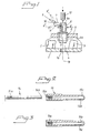
- a mandible is shown in principle as 1.
- the mandible supports teeth 2 and 3 and also exhibits a space 4 situated between said teeth.
- a template 5, e.g. tooth template, surgical template, etc., is fitted to the teeth in a manner known per se .
- the template can exhibit one or more guide sleeves 6, the positions of which are pre-calculated by means of a computer (not shown) in a manner known per se.
- a guide device is shown in principle as 7 and includes a guide part 8 and a handle part 9. The guide and handle parts are connected to each other via a ball bearing race 10 and a part 11 supporting the latter.
- the sleeve 6 is provided with a central aperture 6a with a diameter D.
- the guide part 8 exhibits an external diameter d which is only slightly smaller than the diameter D.
- the guide part 8 thus guides into the aperture 6a in the sleeve 6.
- the guide part 8 is in turn provided with a central aperture 8a, into which a drill 12 is guided when the guide part 8 is lowered into the sleeve 6 for uptake by a drill hole 1a in the mandible.
- Said drill hole constitutes a hole uptake for an implant in a manner known per se. Thanks to the ball bearing race 10 the handle part 9 can be rotated to different height positions, two of which have been denoted 9' and 9" in Figure 1 .
- the guide part 8 is rotatable relative to the sleeve 6 around a longitudinal axis 13 which is common to said sleeves and the drill 12 and the drill hole 1a.
- the handle part is made up of a first part 14 and a second part 15.
- the first part is provided at its back end with an external thread 14a and is provided in its front part with an interaction part 14b, by means of which the first part is able to interact with the ball bearing race referred to above.
- the second part In its back parts the second part exhibits an internal thread 15a, in which the first part can be screwed into the second part by means of its thread 14a.
- the second part At its front end the second part exhibits an internal space 15b.
- the second part exhibits a lateral recess 15c, via which the ball bearing race 10 (see Fig. 1 ) can be inserted into the space with the supporting part 11 extending outside to the sleeve 6.
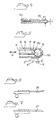
- Figure 3 shows said lateral recess and space in a view that is rotated by 90° relative to Figure 2 .
- Figure 4 shows the design of the lateral groove 15c.
- the lateral groove exhibits a first width B and a second width b.
- the greater width exceeds the diameter or width of the sphere 10
- the smaller width b is less than the diameter of the sphere but exceeds the diameter or cross-sectional area of the supporting part.
- the sphere can thus be inserted into the space 15b at the greater width and advanced towards the front end of the second part into the space 15b (see Fig. 2 ).
- first longitudinal displacement position which has in principle been indicated as 16
- second longitudinal displacement position which has been indicated as 17
- the first part 14 makes it impossible for the sphere 10 to be removed from the space 15b.
- the sphere is rotatable in the space, however, in this position 17 for the first part.
- a third position which has been indicated as 18, the sphere is locked to a front internal wall 15d of the second part 15.
- the supporting member 11 extends to the outside via the lateral recess 15c, at the smaller width b.
- Figures 6 and 7 are intended to show in principle that the guide part can be a guiding member for other types of instruments than drills, e.g. knives.
- the blades of the knives have been indicated as 20 and 21.
Abstract
Description
- The present invention relates to a guide device which is able to interact with a number of sleeves disposed in a tooth template or surgical template and includes a guide part which can be fitted to a corresponding sleeve which is connected to or forms part of a handle part for fitting to the corresponding sleeve of the guide part.
- The invention can inter alia be used in connection with rapid dental treatments, e.g. dental treatments in accordance with the "Teeth in an Hour" concept. When implants are fitted, in said rapid treatments use is made inter alia of surgical templates with sleeves, which constitute guides for guide parts which in turn guide the instrument in question, e.g. drill, knife, etc., in connection with the insertion of the implant. The positions of the sleeves in the surgical template are planned in a manner known per se in a computer.
- The guide part can be such that its external diameter corresponds to an internal diameter of the corresponding tooth template sleeve. The guide part can be made up of a guide sleeve whose central aperture constitutes a guide for a desired instrument, e.g. a drill. The guide part can be supported on a shaft so that it can easily be moved between the various positions for the tooth template sleeves.
- In the dental work in question it is known that there are various degrees of difficulty which are dependent on the various positions of the teeth and of the treatment sites in the oral cavity. The teeth and the spaces in the front parts of the oral cavity are easily accessible, whereas problems can arise in achieving rapid and effective treatment in the case of teeth and spaces in the inner parts of the oral cavity. If a shaft-mounted guide part or shaft-mounted guide parts are also desired for the inner teeth and spaces, there can be problems both in fitting the guide part or guide parts and in preventing the shaft protruding from the guide part from hindering the actual work and causing significant discomfort to the patient. The present invention is intended to solve these problems.
- It is also desirable that the equipment used should be clear-cut and easy to operate and that for example it can be operated with only small actuation movements. It should be easy to change between different guide parts and shafts during the course of the work. There is also a need for the equipment used to be- easy to clean and sterilize. The present invention also solves these problems.
-
US-A-5 743 916 describes a guide device which interacts with a number of guide sleeves disposed in a surgical template. The guide device includes a handle part and a guide part. The guide part can be fitted to a guide sleeve of the surgical template and is connected to the handle part. - The present invention provides guide device, which is able to interact with a number of guide sleeves disposed in a surgical template, the guide device including a handle part and a guide part, which guide part can be fitted to a corresponding guide sleeve of said surgical template and which guide part is connected to the handle part, characterised in that the guide part is disposed with a sphere, and in that the handle part is made up of a first part and a second part which are longitudinally displaceable in relation to each other, the second part exhibits an internal space configured to receive the sphere, and wherein, when the sphere is located in the internal space and the first part is in a first longitudinal displacement position, the first part locks the sphere relative to the second part.
- In a preferred embodiment, when the first part is in a second longitudinal displacement position, the sphere is rotatable but the first part makes it impossible for the sphere to be removed from the internal space. Furthermore, the sphere can be inserted into the internal space when the first part is in a third longitudinal displacement position. The second part may include an internal thread and the first part include an external thread, which can interact with the internal thread. The guide device may comprise a supporting part which supports the sphere, the supporting part exhibiting a diameter or cross-sectional area which is significantly smaller than the diameter of the sphere. The extent to which the diameter or cross-sectional area of the supporting part may be smaller than the diameter of the sphere lies within the range of 50% to 75%. The internal space may be arranged with a first width which exceeds the diameter of the sphere and a second width which is less that the diameter of the sphere but exceeds the diameter or cross-sectional area of the supporting part.
- What is proposed above makes possible a particularly advantageous adjustment function for the handle part where the latter, when the guide part is fitted in a corresponding tooth sleeve, can be given an optimal position where the handle part to the greatest possible extent is prevented from interfering with the dental work while at the same time there can be the least possible discomfort to the patient. The further developments of the inventive idea provide the possibility that small actuation movements can be made in order to attain the different position settings. At the same time the various parts can easily be disassembled for cleaning and sterilisation.
- An embodiment of a guide device according to the invention which is proposed at present will be described below with simultaneous reference to the appended drawing, where
-
Figure 1 shows in vertical section parts of a mandible with teeth and a tooth template arranged in relation to them with a guide sleeve and a guide device with a guide sleeve and handle part and parts of a drill, -
Figure 2 shows in exploded view the first and second parts in the handle part, -
Figure 3 shows in longitudinal section, and rotated by 90° relative to the view inFigure 2 , another part in the handle part, -
Figure 4 shows in longitudinal section, and at reduced scale relative toFigures 2 and 3 , the handle part with the first and second parts, as shown inFigure 2 , assembled, -
Figure 5 shows in longitudinal section parts of the second part, as shown inFigure 2 , with a sphere in place and different longitudinal displacement positions shown in principle for the first part relative to the second part and the ball bearing race, and -
Figures 6 and 7 show in lateral views other types of instruments (knives) which can be fitted to the guide part. - In
Figure 1 a mandible is shown in principle as 1. The mandible supportsteeth space 4 situated between said teeth. Atemplate 5, e.g. tooth template, surgical template, etc., is fitted to the teeth in a manner known per se. The template can exhibit one ormore guide sleeves 6, the positions of which are pre-calculated by means of a computer (not shown) in a manner known per se. A guide device is shown in principle as 7 and includes aguide part 8 and ahandle part 9. The guide and handle parts are connected to each other via a ball bearingrace 10 and apart 11 supporting the latter. Thesleeve 6 is provided with a central aperture 6a with a diameter D. Theguide part 8 exhibits an external diameter d which is only slightly smaller than the diameter D. Theguide part 8 thus guides into the aperture 6a in thesleeve 6. Theguide part 8 is in turn provided with a central aperture 8a, into which adrill 12 is guided when theguide part 8 is lowered into thesleeve 6 for uptake by adrill hole 1a in the mandible. Said drill hole constitutes a hole uptake for an implant in a manner known per se. Thanks to the ball bearingrace 10 thehandle part 9 can be rotated to different height positions, two of which have been denoted 9' and 9" inFigure 1 . In addition theguide part 8 is rotatable relative to thesleeve 6 around alongitudinal axis 13 which is common to said sleeves and thedrill 12 and thedrill hole 1a. - In accordance with
Figure 2 the handle part is made up of afirst part 14 and asecond part 15. The first part is provided at its back end with an external thread 14a and is provided in its front part with an interaction part 14b, by means of which the first part is able to interact with the ball bearing race referred to above. In its back parts the second part exhibits aninternal thread 15a, in which the first part can be screwed into the second part by means of its thread 14a. At its front end the second part exhibits aninternal space 15b. In addition the second part exhibits alateral recess 15c, via which the ball bearing race 10 (seeFig. 1 ) can be inserted into the space with the supportingpart 11 extending outside to thesleeve 6. -
Figure 3 shows said lateral recess and space in a view that is rotated by 90° relative toFigure 2 . -
Figure 4 shows the design of thelateral groove 15c. The lateral groove exhibits a first width B and a second width b. The greater width exceeds the diameter or width of thesphere 10, while the smaller width b is less than the diameter of the sphere but exceeds the diameter or cross-sectional area of the supporting part. The sphere can thus be inserted into thespace 15b at the greater width and advanced towards the front end of the second part into thespace 15b (seeFig. 2 ). - In accordance with
Figure 5 , different longitudinal displacement positions relative to thesecond part 15 can be assigned to thefirst part 14. The first longitudinal displacement position, which has in principle been indicated as 16, allows thesphere 10 to be inserted into thespace 15b and pushed forward or advanced into thespace 15b. In a second longitudinal displacement position, which has been indicated as 17, thefirst part 14 makes it impossible for thesphere 10 to be removed from thespace 15b. The sphere is rotatable in the space, however, in thisposition 17 for the first part. In a third position, which has been indicated as 18, the sphere is locked to a frontinternal wall 15d of thesecond part 15. Inpositions member 11 extends to the outside via thelateral recess 15c, at the smaller width b. Said smaller width will thus exceed the diameter d' or cross-sectional area of the supporting member. The rotatability of the sphere in thesecond position 17 allows the supporting member inFigure 5 to extend to an optionally adjusted position in the plane of the paper. Two further rotational positions have been shown inFigure 5 as 11' and 11". Depending on the choice of the width b and the diameter d', the supporting member can also be actuated relative to the handle part, or vice versa, even at right angles to the plane of the figure in accordance withFigure 5 . For thesphere 10 the diameter D' thereof, which will be less than the width B but exceed the width b, has also been indicated inFigure 5 . It can be seen that the construction described above makes possible a large number of individual rotational positions between the second part and theguide part 8. The actuation directions for the first part relative to the second part are shown as 19 inFigure 5 . -
Figures 6 and 7 are intended to show in principle that the guide part can be a guiding member for other types of instruments than drills, e.g. knives. InFigures 6 and 7 the blades of the knives have been indicated as 20 and 21. - The invention is not limited to the embodiments shown above as examples but can be subject to modifications within the scope of the following claims.
Claims (7)
- Guide device (7), which is able to interact with a number of guide sleeves (6) disposed in a surgical template (5), the guide device (7) including
a handle part (9) and
a guide part (8), which guide part (8) can be fitted to a corresponding guide sleeve (6) of said surgical template (5) and which guide part (8) is connected to the handle part (9),
characterised in that the guide part (8) is disposed with a sphere (10), and
in that the handle part (9) is made up of a first part (14) and a second part (15) which are longitudinally displaceable in relation to each other, the second part (15) exhibits an internal space (15b) configured to receive the sphere (10), and wherein, when the sphere (10) is located in the internal space (15b) and the first part (14) is in a first longitudinal displacement position (18), the first part (14) locks the sphere (10) relative to the second part. - Guide device (7) as claimed in Claim 1, characterised in that when the first part (14) is in a second longitudinal displacement position (17), the sphere (10) is rotatable but the first part (14) makes it impossible for the sphere (10) to be removed from the internal space (15b).
- Guide sleeve (7) as claimed in Claim 1 or 2, characterised in that the sphere (10) can be inserted into the internal space (15b) when the first part (14) is in a third longitudinal displacement position (16).
- Guide device (7) as claimed in any of Claims 1 to 3, characterised in that the second part (15) includes an internal thread (15a) and the first part (14) includes an external thread (14a), which can interact with the internal thread (15a).
- Guide device (7) as claimed in any of Claims 1 to 4, characterised in that the guide device (7) comprises a supporting part (11) which supports the sphere (10), the supporting part exhibiting a diameter or cross-sectional area which is significantly smaller than the diameter of the sphere (10).
- Guide device (7) as claimed in Claim 5, characterised in that the extent to which the diameter or cross-sectional area of the supporting part (11) is smaller than the diameter of the sphere (10) lies within the range of 50% to 75%.
- Guide sleeve (7) as claimed in Claim 5 and 6, characterised in that the internal space (15b) is arranged with a first width which exceeds the diameter of the sphere (10) and a second width which is less that the diameter of the sphere (10) but exceeds the diameter or cross-sectional area of the supporting part (11).
Priority Applications (1)
| Application Number | Priority Date | Filing Date | Title |
|---|---|---|---|
| EP10009892A EP2295002A3 (en) | 2004-08-05 | 2005-07-04 | Handle part connectable to a guide part |
Applications Claiming Priority (2)
| Application Number | Priority Date | Filing Date | Title |
|---|---|---|---|
| SE0401984A SE527504C2 (en) | 2004-08-05 | 2004-08-05 | Control device cooperable with a number of sleeves arranged in tooth template |
| PCT/SE2005/001074 WO2006014130A1 (en) | 2004-08-05 | 2005-07-04 | Guide device able to interact with a number of sleeves disposed in a tooth template |
Related Child Applications (1)
| Application Number | Title | Priority Date | Filing Date |
|---|---|---|---|
| EP10009892.0 Division-Into | 2010-09-20 |
Publications (2)
| Publication Number | Publication Date |
|---|---|
| EP1781201A1 EP1781201A1 (en) | 2007-05-09 |
| EP1781201B1 true EP1781201B1 (en) | 2011-06-29 |
Family
ID=32960364
Family Applications (2)
| Application Number | Title | Priority Date | Filing Date |
|---|---|---|---|
| EP05756985A Active EP1781201B1 (en) | 2004-08-05 | 2005-07-04 | Guide device able to interact with a number of sleeves disposed in a tooth template |
| EP10009892A Withdrawn EP2295002A3 (en) | 2004-08-05 | 2005-07-04 | Handle part connectable to a guide part |
Family Applications After (1)
| Application Number | Title | Priority Date | Filing Date |
|---|---|---|---|
| EP10009892A Withdrawn EP2295002A3 (en) | 2004-08-05 | 2005-07-04 | Handle part connectable to a guide part |
Country Status (7)
| Country | Link |
|---|---|
| US (2) | US7572125B2 (en) |
| EP (2) | EP1781201B1 (en) |
| JP (1) | JP4756192B2 (en) |
| AT (1) | ATE514390T1 (en) |
| ES (1) | ES2368928T3 (en) |
| SE (1) | SE527504C2 (en) |
| WO (1) | WO2006014130A1 (en) |
Families Citing this family (59)
| Publication number | Priority date | Publication date | Assignee | Title |
|---|---|---|---|---|
| SE522958C2 (en) | 2000-12-29 | 2004-03-16 | Nobel Biocare Ab | Procedure, arrangement (device) and programs at or for prosthetic installation |
| SE520765C2 (en) * | 2001-12-28 | 2003-08-19 | Nobel Biocare Ab | Device and arrangement for inserting holes for bone implants by means of template, preferably jawbones |
| SE526665C2 (en) * | 2002-12-30 | 2005-10-25 | Nobel Biocare Ab | Device for dental screw-in arrangement |
| SE526666C2 (en) * | 2002-12-30 | 2005-10-25 | Nobel Biocare Ab | Device and arrangement for fixture installation |
| SE526223C2 (en) * | 2003-12-10 | 2005-08-02 | Nobel Biocare Ab | System and apparatus for the manufacture and insertion of dental bridge construction |
| SE527503C2 (en) * | 2004-08-05 | 2006-03-21 | Nobel Biocare Ab | Device and method for facilitating application to correct position of tooth or tooth residue template |
| SE527504C2 (en) * | 2004-08-05 | 2006-03-21 | Nobel Biocare Ab | Control device cooperable with a number of sleeves arranged in tooth template |
| EP1906862B1 (en) | 2005-06-30 | 2018-05-23 | Biomet 3i, LLC | Method of creating a dental laboratory model |
| US11219511B2 (en) | 2005-10-24 | 2022-01-11 | Biomet 3I, Llc | Methods for placing an implant analog in a physical model of the patient's mouth |
| US8257083B2 (en) | 2005-10-24 | 2012-09-04 | Biomet 3I, Llc | Methods for placing an implant analog in a physical model of the patient's mouth |
| US8540510B2 (en) | 2006-05-04 | 2013-09-24 | Nobel Biocare Services Ag | Device for securing a dental implant in bone tissue, a method for making a surgical template and a method of securing a dental implant in bone tissue |
| US10206757B2 (en) | 2007-01-10 | 2019-02-19 | Nobel Biocare Services Ag | Method and system for dental planning and production |
| US8206153B2 (en) | 2007-05-18 | 2012-06-26 | Biomet 3I, Inc. | Method for selecting implant components |
| US8087934B2 (en) | 2007-05-29 | 2012-01-03 | Immediate Implant Technologies, Llc | Oral implant placement system and method |
| US8465282B2 (en) * | 2007-05-29 | 2013-06-18 | Immediate Implant Technologies, Llc | Oral implant placement system and method |
| EP2397102A1 (en) | 2007-08-22 | 2011-12-21 | Straumann Holding AG | Drill guide |
| EP2060240A3 (en) | 2007-11-16 | 2009-08-12 | Biomet 3i, LLC | Components for use with a surgical guide for dental implant placement |
| EP2103276B1 (en) * | 2008-03-19 | 2019-06-19 | Nobel Biocare Services AG | Repositioning of components related to cranial surgical procedures in a patient |
| ES2683119T3 (en) | 2008-04-15 | 2018-09-25 | Biomet 3I, Llc | Method of creating an accurate digital dental model of bones and soft tissues |
| WO2009146195A1 (en) | 2008-04-16 | 2009-12-03 | Biomet 3I, Llc | Method for pre-operative visualization of instrumentation used with a surgical guide for dental implant placement |
| WO2010028811A1 (en) | 2008-09-10 | 2010-03-18 | Nobel Biocare Services Ag | Device and procedure for implanting a dental implant |
| EP2368515A1 (en) | 2008-12-01 | 2011-09-28 | Straumann Holding AG | Drill sleeve for a dental drill |
| EP2196162B1 (en) * | 2008-12-15 | 2016-10-12 | Straumann Holding AG | Drill guide |
| US8640338B2 (en) | 2009-02-02 | 2014-02-04 | Viax Dental Technologies, LLC | Method of preparation for restoring tooth structure |
| US20100192375A1 (en) | 2009-02-02 | 2010-08-05 | Remedent Nv | Method for producing a dentist tool |
| EP2254068B1 (en) | 2009-05-18 | 2020-08-19 | Nobel Biocare Services AG | Method and system providing improved data matching for virtual planning |
| JP4971400B2 (en) * | 2009-07-17 | 2012-07-11 | 株式会社アイキャット | Wrench for drill guide |
| ES2596828T3 (en) * | 2009-09-07 | 2017-01-12 | Nobel Biocare Services Ag | Components for guided threading of a bone |
| ES2710179T3 (en) | 2009-09-07 | 2019-04-23 | Nobel Biocare Services Ag | Implementation set |
| WO2011037205A1 (en) * | 2009-09-24 | 2011-03-31 | 株式会社アイキャット | Drill guide wrench |
| CA2724093A1 (en) * | 2009-12-17 | 2011-06-17 | Straumann Holding Ag | Dental tools for guided surgery |
| EP2620122A4 (en) * | 2010-09-21 | 2014-05-07 | Implantdent Co Ltd | Surgical guide making tool and surgical guide making method |
| TWI629050B (en) * | 2010-11-26 | 2018-07-11 | 鄭伯堃 | Components for dental positioning stent |
| EP2462893B8 (en) | 2010-12-07 | 2014-12-10 | Biomet 3i, LLC | Universal scanning member for use on dental implant and dental implant analogs |
| DE102011003557B9 (en) | 2011-02-03 | 2012-09-06 | Sirona Dental Systems Gmbh | Drilling template for a dental implant, a method for producing this surgical template and a device for checking the drilling template and their use |
| EP3777760A1 (en) | 2011-05-16 | 2021-02-17 | Biomet 3I, LLC | Temporary abutment with combination of scanning features and provisionalization features |
| BR122020013944B1 (en) | 2011-05-26 | 2021-06-08 | Viax Dental Technologies, LLC | dental system, dental coating, and method for producing a dental coating |
| US20130023888A1 (en) * | 2011-07-22 | 2013-01-24 | Woncheol Choi | Surgical drill guide adapter with a handle and detachable head |
| US10363115B2 (en) | 2011-09-16 | 2019-07-30 | Ibur, Llc | Method of using an endentulous surgical guide |
| US9504533B2 (en) | 2011-09-16 | 2016-11-29 | Ibur, Llc | Edentulous surgical guide |
| US9089382B2 (en) | 2012-01-23 | 2015-07-28 | Biomet 3I, Llc | Method and apparatus for recording spatial gingival soft tissue relationship to implant placement within alveolar bone for immediate-implant placement |
| US9452032B2 (en) | 2012-01-23 | 2016-09-27 | Biomet 3I, Llc | Soft tissue preservation temporary (shell) immediate-implant abutment with biological active surface |
| KR101159560B1 (en) * | 2012-04-02 | 2012-06-25 | (주)애크로덴트 | Bonepen, bonepin, bonepen set, bonepin set and bonepen kit including initial drill thereof |
| US9028252B1 (en) * | 2012-08-27 | 2015-05-12 | Navident Medical Device Ltd. | Device, system and method for in-situ drill guide sleeve orientation |
| GB201216224D0 (en) | 2012-09-12 | 2012-10-24 | Nobel Biocare Services Ag | An improved virtual splint |
| GB201216230D0 (en) | 2012-09-12 | 2012-10-24 | Nobel Biocare Services Ag | An improved surgical template |
| GB201216214D0 (en) | 2012-09-12 | 2012-10-24 | Nobel Biocare Services Ag | A digital splint |
| US20140080092A1 (en) | 2012-09-14 | 2014-03-20 | Biomet 3I, Llc | Temporary dental prosthesis for use in developing final dental prosthesis |
| US8926328B2 (en) | 2012-12-27 | 2015-01-06 | Biomet 3I, Llc | Jigs for placing dental implant analogs in models and methods of doing the same |
| DE202013001415U1 (en) | 2013-01-22 | 2013-03-05 | Bego Implant Systems Gmbh & Co. Kg | Sleeve system for template-guided dental implantology |
| DE202013000576U1 (en) | 2013-01-22 | 2014-04-23 | Bego Implant Systems Gmbh & Co. Kg | Sleeve system for template-guided dental implantology |
| US20140272793A1 (en) * | 2013-03-15 | 2014-09-18 | Grant Dental Technology Corporation | Dental implant instrumentation and methods |
| EP3998040A1 (en) | 2013-12-20 | 2022-05-18 | Biomet 3i, LLC | Dental method for developing custom prostheses through scanning of coded members |
| US9283055B2 (en) | 2014-04-01 | 2016-03-15 | FPJ Enterprises, LLC | Method for establishing drill trajectory for dental implants |
| US9700390B2 (en) | 2014-08-22 | 2017-07-11 | Biomet 3I, Llc | Soft-tissue preservation arrangement and method |
| EP3267936A4 (en) | 2015-03-09 | 2018-12-26 | Stephen J. Chu | Gingival ovate pontic and methods of using the same |
| US11007035B2 (en) | 2017-03-16 | 2021-05-18 | Viax Dental Technologies Llc | System for preparing teeth for the placement of veneers |
| US11540900B2 (en) * | 2018-05-03 | 2023-01-03 | The United States Of America As Represented By The Secretary Of The Navy | Dental ridge augmentation matrix with integrated dental implant surgical drill guide system |
| BE1027356B1 (en) * | 2019-06-12 | 2021-01-18 | Dental Vision B V B A | DENTAL PROSTHESIS SYSTEM AND METHOD FOR MANUFACTURING A DENTAL PROSTHESIS |
Family Cites Families (17)
| Publication number | Priority date | Publication date | Assignee | Title |
|---|---|---|---|---|
| US4364381A (en) * | 1980-01-31 | 1982-12-21 | Sher Jay H | Surgical clamp and drill-guiding instrument |
| JPH078285B2 (en) * | 1987-12-22 | 1995-02-01 | 弘 大口 | Implant planting groove forming device |
| US5743916A (en) | 1990-07-13 | 1998-04-28 | Human Factors Industrial Design, Inc. | Drill guide with removable ferrules |
| US5320529A (en) * | 1992-09-09 | 1994-06-14 | Howard C. Weitzman | Method and apparatus for locating an ideal site for a dental implant and for the precise surgical placement of that implant |
| SE500383C2 (en) * | 1992-11-26 | 1994-06-13 | Medevelop Ab | Double anchored tooth fixture |
| US5564926A (en) * | 1992-11-26 | 1996-10-15 | Medevelop Ab | Anchoring element for anchorage in bone tissue |
| US5302122A (en) * | 1993-04-05 | 1994-04-12 | Milne Robert H | Dentistry implant paralleling device and method of installing implants |
| NL9301308A (en) * | 1993-07-26 | 1995-02-16 | Willem Frederick Van Nifterick | Method of securing a dental prosthesis to implants in a patient's jawbone and using means thereof. |
| IL118371A (en) * | 1996-05-22 | 2000-06-29 | Conley Roy | Drill guide |
| JPH10294159A (en) * | 1997-04-18 | 1998-11-04 | Yazaki Corp | Relay device for use between relative rotation member |
| US5967777A (en) * | 1997-11-24 | 1999-10-19 | Klein; Michael | Surgical template assembly and method for drilling and installing dental implants |
| US6099311A (en) * | 1999-07-28 | 2000-08-08 | Sulzer Calcitek Inc. | Abutment delivery system |
| DE20002376U1 (en) * | 2000-02-11 | 2000-05-18 | Hein Wolfram | Interdental teeth cleaner with flexible cleaning tip and handle |
| EP1317910A1 (en) | 2001-12-06 | 2003-06-11 | KerrHawe SA | Medical instrument for use with liquids |
| FR2836372B1 (en) * | 2002-02-28 | 2004-06-04 | Obl | METHOD AND DEVICE FOR PLACING DENTAL IMPLANTS |
| US7021934B2 (en) * | 2003-01-21 | 2006-04-04 | Zimmer Dental, Inc. | Multi-adjustable drill guide and framework system for dental prosthetics |
| SE527504C2 (en) * | 2004-08-05 | 2006-03-21 | Nobel Biocare Ab | Control device cooperable with a number of sleeves arranged in tooth template |
-
2004
- 2004-08-05 SE SE0401984A patent/SE527504C2/en unknown
-
2005
- 2005-07-04 EP EP05756985A patent/EP1781201B1/en active Active
- 2005-07-04 ES ES05756985T patent/ES2368928T3/en active Active
- 2005-07-04 AT AT05756985T patent/ATE514390T1/en not_active IP Right Cessation
- 2005-07-04 JP JP2007524763A patent/JP4756192B2/en active Active
- 2005-07-04 WO PCT/SE2005/001074 patent/WO2006014130A1/en active Application Filing
- 2005-07-04 US US11/573,193 patent/US7572125B2/en active Active
- 2005-07-04 EP EP10009892A patent/EP2295002A3/en not_active Withdrawn
-
2009
- 2009-08-10 US US12/538,811 patent/US8157563B2/en active Active
Also Published As
| Publication number | Publication date |
|---|---|
| WO2006014130A1 (en) | 2006-02-09 |
| US7572125B2 (en) | 2009-08-11 |
| US20070281270A1 (en) | 2007-12-06 |
| EP2295002A3 (en) | 2012-07-25 |
| ATE514390T1 (en) | 2011-07-15 |
| US8157563B2 (en) | 2012-04-17 |
| SE0401984D0 (en) | 2004-08-05 |
| EP2295002A2 (en) | 2011-03-16 |
| ES2368928T3 (en) | 2011-11-23 |
| SE0401984L (en) | 2006-02-06 |
| SE527504C2 (en) | 2006-03-21 |
| US20090298009A1 (en) | 2009-12-03 |
| JP2008508931A (en) | 2008-03-27 |
| JP4756192B2 (en) | 2011-08-24 |
| EP1781201A1 (en) | 2007-05-09 |
Similar Documents
| Publication | Publication Date | Title |
|---|---|---|
| EP1781201B1 (en) | Guide device able to interact with a number of sleeves disposed in a tooth template | |
| EP2196162B1 (en) | Drill guide | |
| US10820964B2 (en) | Drill guide having a limit stop | |
| US9039413B2 (en) | Dental tools for guided surgery | |
| US20170071696A1 (en) | Drilling tool for dental implant surgery, comprising a stepped guide | |
| US11730573B2 (en) | Fixation pin | |
| RU138962U1 (en) | SURGICAL GUIDE DEVICE | |
| US11376099B2 (en) | Dental surgery guide system | |
| EP2227168A1 (en) | Stop element for a surgical tool | |
| JP2009207688A (en) | Drilling instrument for implanting implant and handpiece for implant | |
| EP2140827A1 (en) | Implant surgical kit for computer-assisted procedures | |
| KR101807564B1 (en) | Drill for implant and handpiece comprising it | |
| KR200453961Y1 (en) | Rotatable dental blade holder during surgery | |
| JPH1043194A (en) | Endoscopic instrument |
Legal Events
| Date | Code | Title | Description |
|---|---|---|---|
| PUAI | Public reference made under article 153(3) epc to a published international application that has entered the european phase |
Free format text: ORIGINAL CODE: 0009012 |
|
| 17P | Request for examination filed |
Effective date: 20070305 |
|
| AK | Designated contracting states |
Kind code of ref document: A1 Designated state(s): AT BE BG CH CY CZ DE DK EE ES FI FR GB GR HU IE IS IT LI LT LU LV MC NL PL PT RO SE SI SK TR |
|
| DAX | Request for extension of the european patent (deleted) | ||
| 17Q | First examination report despatched |
Effective date: 20080116 |
|
| RAP1 | Party data changed (applicant data changed or rights of an application transferred) |
Owner name: NOBEL BIOCARE SERVICES AG |
|
| GRAP | Despatch of communication of intention to grant a patent |
Free format text: ORIGINAL CODE: EPIDOSNIGR1 |
|
| GRAS | Grant fee paid |
Free format text: ORIGINAL CODE: EPIDOSNIGR3 |
|
| GRAA | (expected) grant |
Free format text: ORIGINAL CODE: 0009210 |
|
| AK | Designated contracting states |
Kind code of ref document: B1 Designated state(s): AT BE BG CH CY CZ DE DK EE ES FI FR GB GR HU IE IS IT LI LT LU LV MC NL PL PT RO SE SI SK TR |
|
| REG | Reference to a national code |
Ref country code: GB Ref legal event code: FG4D |
|
| REG | Reference to a national code |
Ref country code: CH Ref legal event code: EP |
|
| REG | Reference to a national code |
Ref country code: CH Ref legal event code: NV Representative=s name: E. BLUM & CO. AG PATENT- UND MARKENANWAELTE VSP |
|
| REG | Reference to a national code |
Ref country code: IE Ref legal event code: FG4D |
|
| REG | Reference to a national code |
Ref country code: DE Ref legal event code: R096 Ref document number: 602005028764 Country of ref document: DE Effective date: 20110818 |
|
| REG | Reference to a national code |
Ref country code: NL Ref legal event code: VDEP Effective date: 20110629 |
|
| PG25 | Lapsed in a contracting state [announced via postgrant information from national office to epo] |
Ref country code: SE Free format text: LAPSE BECAUSE OF FAILURE TO SUBMIT A TRANSLATION OF THE DESCRIPTION OR TO PAY THE FEE WITHIN THE PRESCRIBED TIME-LIMIT Effective date: 20110629 Ref country code: LT Free format text: LAPSE BECAUSE OF FAILURE TO SUBMIT A TRANSLATION OF THE DESCRIPTION OR TO PAY THE FEE WITHIN THE PRESCRIBED TIME-LIMIT Effective date: 20110629 |
|
| REG | Reference to a national code |
Ref country code: ES Ref legal event code: FG2A Ref document number: 2368928 Country of ref document: ES Kind code of ref document: T3 Effective date: 20111123 |
|
| PG25 | Lapsed in a contracting state [announced via postgrant information from national office to epo] |
Ref country code: FI Free format text: LAPSE BECAUSE OF FAILURE TO SUBMIT A TRANSLATION OF THE DESCRIPTION OR TO PAY THE FEE WITHIN THE PRESCRIBED TIME-LIMIT Effective date: 20110629 Ref country code: GR Free format text: LAPSE BECAUSE OF FAILURE TO SUBMIT A TRANSLATION OF THE DESCRIPTION OR TO PAY THE FEE WITHIN THE PRESCRIBED TIME-LIMIT Effective date: 20110930 Ref country code: LV Free format text: LAPSE BECAUSE OF FAILURE TO SUBMIT A TRANSLATION OF THE DESCRIPTION OR TO PAY THE FEE WITHIN THE PRESCRIBED TIME-LIMIT Effective date: 20110629 Ref country code: AT Free format text: LAPSE BECAUSE OF FAILURE TO SUBMIT A TRANSLATION OF THE DESCRIPTION OR TO PAY THE FEE WITHIN THE PRESCRIBED TIME-LIMIT Effective date: 20110629 Ref country code: SI Free format text: LAPSE BECAUSE OF FAILURE TO SUBMIT A TRANSLATION OF THE DESCRIPTION OR TO PAY THE FEE WITHIN THE PRESCRIBED TIME-LIMIT Effective date: 20110629 |
|
| PG25 | Lapsed in a contracting state [announced via postgrant information from national office to epo] |
Ref country code: BE Free format text: LAPSE BECAUSE OF FAILURE TO SUBMIT A TRANSLATION OF THE DESCRIPTION OR TO PAY THE FEE WITHIN THE PRESCRIBED TIME-LIMIT Effective date: 20110629 |
|
| PG25 | Lapsed in a contracting state [announced via postgrant information from national office to epo] |
Ref country code: IS Free format text: LAPSE BECAUSE OF FAILURE TO SUBMIT A TRANSLATION OF THE DESCRIPTION OR TO PAY THE FEE WITHIN THE PRESCRIBED TIME-LIMIT Effective date: 20111029 Ref country code: CZ Free format text: LAPSE BECAUSE OF FAILURE TO SUBMIT A TRANSLATION OF THE DESCRIPTION OR TO PAY THE FEE WITHIN THE PRESCRIBED TIME-LIMIT Effective date: 20110629 Ref country code: EE Free format text: LAPSE BECAUSE OF FAILURE TO SUBMIT A TRANSLATION OF THE DESCRIPTION OR TO PAY THE FEE WITHIN THE PRESCRIBED TIME-LIMIT Effective date: 20110629 Ref country code: NL Free format text: LAPSE BECAUSE OF FAILURE TO SUBMIT A TRANSLATION OF THE DESCRIPTION OR TO PAY THE FEE WITHIN THE PRESCRIBED TIME-LIMIT Effective date: 20110629 Ref country code: PT Free format text: LAPSE BECAUSE OF FAILURE TO SUBMIT A TRANSLATION OF THE DESCRIPTION OR TO PAY THE FEE WITHIN THE PRESCRIBED TIME-LIMIT Effective date: 20111031 |
|
| PG25 | Lapsed in a contracting state [announced via postgrant information from national office to epo] |
Ref country code: PL Free format text: LAPSE BECAUSE OF FAILURE TO SUBMIT A TRANSLATION OF THE DESCRIPTION OR TO PAY THE FEE WITHIN THE PRESCRIBED TIME-LIMIT Effective date: 20110629 Ref country code: RO Free format text: LAPSE BECAUSE OF FAILURE TO SUBMIT A TRANSLATION OF THE DESCRIPTION OR TO PAY THE FEE WITHIN THE PRESCRIBED TIME-LIMIT Effective date: 20110629 Ref country code: SK Free format text: LAPSE BECAUSE OF FAILURE TO SUBMIT A TRANSLATION OF THE DESCRIPTION OR TO PAY THE FEE WITHIN THE PRESCRIBED TIME-LIMIT Effective date: 20110629 Ref country code: MC Free format text: LAPSE BECAUSE OF NON-PAYMENT OF DUE FEES Effective date: 20110731 Ref country code: CY Free format text: LAPSE BECAUSE OF FAILURE TO SUBMIT A TRANSLATION OF THE DESCRIPTION OR TO PAY THE FEE WITHIN THE PRESCRIBED TIME-LIMIT Effective date: 20110629 |
|
| REG | Reference to a national code |
Ref country code: IE Ref legal event code: MM4A |
|
| PLBE | No opposition filed within time limit |
Free format text: ORIGINAL CODE: 0009261 |
|
| STAA | Information on the status of an ep patent application or granted ep patent |
Free format text: STATUS: NO OPPOSITION FILED WITHIN TIME LIMIT |
|
| PG25 | Lapsed in a contracting state [announced via postgrant information from national office to epo] |
Ref country code: IT Free format text: LAPSE BECAUSE OF FAILURE TO SUBMIT A TRANSLATION OF THE DESCRIPTION OR TO PAY THE FEE WITHIN THE PRESCRIBED TIME-LIMIT Effective date: 20110629 |
|
| 26N | No opposition filed |
Effective date: 20120330 |
|
| PG25 | Lapsed in a contracting state [announced via postgrant information from national office to epo] |
Ref country code: DK Free format text: LAPSE BECAUSE OF FAILURE TO SUBMIT A TRANSLATION OF THE DESCRIPTION OR TO PAY THE FEE WITHIN THE PRESCRIBED TIME-LIMIT Effective date: 20110629 |
|
| PG25 | Lapsed in a contracting state [announced via postgrant information from national office to epo] |
Ref country code: IE Free format text: LAPSE BECAUSE OF NON-PAYMENT OF DUE FEES Effective date: 20110704 |
|
| REG | Reference to a national code |
Ref country code: DE Ref legal event code: R097 Ref document number: 602005028764 Country of ref document: DE Effective date: 20120330 |
|
| PG25 | Lapsed in a contracting state [announced via postgrant information from national office to epo] |
Ref country code: LU Free format text: LAPSE BECAUSE OF NON-PAYMENT OF DUE FEES Effective date: 20110704 |
|
| PG25 | Lapsed in a contracting state [announced via postgrant information from national office to epo] |
Ref country code: BG Free format text: LAPSE BECAUSE OF FAILURE TO SUBMIT A TRANSLATION OF THE DESCRIPTION OR TO PAY THE FEE WITHIN THE PRESCRIBED TIME-LIMIT Effective date: 20110929 |
|
| PG25 | Lapsed in a contracting state [announced via postgrant information from national office to epo] |
Ref country code: TR Free format text: LAPSE BECAUSE OF FAILURE TO SUBMIT A TRANSLATION OF THE DESCRIPTION OR TO PAY THE FEE WITHIN THE PRESCRIBED TIME-LIMIT Effective date: 20110629 |
|
| PG25 | Lapsed in a contracting state [announced via postgrant information from national office to epo] |
Ref country code: HU Free format text: LAPSE BECAUSE OF FAILURE TO SUBMIT A TRANSLATION OF THE DESCRIPTION OR TO PAY THE FEE WITHIN THE PRESCRIBED TIME-LIMIT Effective date: 20110629 |
|
| REG | Reference to a national code |
Ref country code: FR Ref legal event code: PLFP Year of fee payment: 12 |
|
| REG | Reference to a national code |
Ref country code: FR Ref legal event code: PLFP Year of fee payment: 13 |
|
| REG | Reference to a national code |
Ref country code: FR Ref legal event code: PLFP Year of fee payment: 14 |
|
| PGFP | Annual fee paid to national office [announced via postgrant information from national office to epo] |
Ref country code: ES Payment date: 20190916 Year of fee payment: 15 |
|
| REG | Reference to a national code |
Ref country code: ES Ref legal event code: FD2A Effective date: 20211202 |
|
| PG25 | Lapsed in a contracting state [announced via postgrant information from national office to epo] |
Ref country code: ES Free format text: LAPSE BECAUSE OF NON-PAYMENT OF DUE FEES Effective date: 20200705 |
|
| P01 | Opt-out of the competence of the unified patent court (upc) registered |
Effective date: 20230515 |
|
| PGFP | Annual fee paid to national office [announced via postgrant information from national office to epo] |
Ref country code: FR Payment date: 20230620 Year of fee payment: 19 |
|
| REG | Reference to a national code |
Ref country code: DE Ref legal event code: R082 Ref document number: 602005028764 Country of ref document: DE Representative=s name: GLAWE DELFS MOLL PARTNERSCHAFT MBB VON PATENT-, DE |
|
| PGFP | Annual fee paid to national office [announced via postgrant information from national office to epo] |
Ref country code: GB Payment date: 20230601 Year of fee payment: 19 Ref country code: CH Payment date: 20230801 Year of fee payment: 19 |
|
| PGFP | Annual fee paid to national office [announced via postgrant information from national office to epo] |
Ref country code: DE Payment date: 20230531 Year of fee payment: 19 |