EP1742017A2 - A monitoring arrangement - Google Patents
A monitoring arrangement Download PDFInfo
- Publication number
- EP1742017A2 EP1742017A2 EP06252996A EP06252996A EP1742017A2 EP 1742017 A2 EP1742017 A2 EP 1742017A2 EP 06252996 A EP06252996 A EP 06252996A EP 06252996 A EP06252996 A EP 06252996A EP 1742017 A2 EP1742017 A2 EP 1742017A2
- Authority
- EP
- European Patent Office
- Prior art keywords
- arrangement
- camera
- target
- rotating component
- light
- Prior art date
- Legal status (The legal status is an assumption and is not a legal conclusion. Google has not performed a legal analysis and makes no representation as to the accuracy of the status listed.)
- Granted
Links
Images


Classifications
-
- G—PHYSICS
- G03—PHOTOGRAPHY; CINEMATOGRAPHY; ANALOGOUS TECHNIQUES USING WAVES OTHER THAN OPTICAL WAVES; ELECTROGRAPHY; HOLOGRAPHY
- G03B—APPARATUS OR ARRANGEMENTS FOR TAKING PHOTOGRAPHS OR FOR PROJECTING OR VIEWING THEM; APPARATUS OR ARRANGEMENTS EMPLOYING ANALOGOUS TECHNIQUES USING WAVES OTHER THAN OPTICAL WAVES; ACCESSORIES THEREFOR
- G03B15/00—Special procedures for taking photographs; Apparatus therefor
- G03B15/02—Illuminating scene
-
- G—PHYSICS
- G01—MEASURING; TESTING
- G01N—INVESTIGATING OR ANALYSING MATERIALS BY DETERMINING THEIR CHEMICAL OR PHYSICAL PROPERTIES
- G01N21/00—Investigating or analysing materials by the use of optical means, i.e. using sub-millimetre waves, infrared, visible or ultraviolet light
- G01N21/84—Systems specially adapted for particular applications
- G01N21/88—Investigating the presence of flaws or contamination
- G01N21/8806—Specially adapted optical and illumination features
-
- G—PHYSICS
- G03—PHOTOGRAPHY; CINEMATOGRAPHY; ANALOGOUS TECHNIQUES USING WAVES OTHER THAN OPTICAL WAVES; ELECTROGRAPHY; HOLOGRAPHY
- G03B—APPARATUS OR ARRANGEMENTS FOR TAKING PHOTOGRAPHS OR FOR PROJECTING OR VIEWING THEM; APPARATUS OR ARRANGEMENTS EMPLOYING ANALOGOUS TECHNIQUES USING WAVES OTHER THAN OPTICAL WAVES; ACCESSORIES THEREFOR
- G03B15/00—Special procedures for taking photographs; Apparatus therefor
- G03B15/16—Special procedures for taking photographs; Apparatus therefor for photographing the track of moving objects
-
- G—PHYSICS
- G03—PHOTOGRAPHY; CINEMATOGRAPHY; ANALOGOUS TECHNIQUES USING WAVES OTHER THAN OPTICAL WAVES; ELECTROGRAPHY; HOLOGRAPHY
- G03B—APPARATUS OR ARRANGEMENTS FOR TAKING PHOTOGRAPHS OR FOR PROJECTING OR VIEWING THEM; APPARATUS OR ARRANGEMENTS EMPLOYING ANALOGOUS TECHNIQUES USING WAVES OTHER THAN OPTICAL WAVES; ACCESSORIES THEREFOR
- G03B39/00—High-speed photography
-
- H—ELECTRICITY
- H04—ELECTRIC COMMUNICATION TECHNIQUE
- H04N—PICTORIAL COMMUNICATION, e.g. TELEVISION
- H04N23/00—Cameras or camera modules comprising electronic image sensors; Control thereof
- H04N23/56—Cameras or camera modules comprising electronic image sensors; Control thereof provided with illuminating means
Definitions
- the present invention relates to monitoring arrangements and more particularly to such monitoring arrangements utilised with regard to rotating components such as turbine blade assemblies in a gas turbine engine.
- rotating components will be subject to varying stresses and strains during use and therefore generally each of these components will distort and become displaced.
- a particular problem with respect to turbine blade assemblies in gas turbine engines is a so called blade-off situation where a blade becomes fully or partially detached or at least displaced causing rubbing with other components within the assembly. In such circumstances it is important to determine the varying distortions and displacements which precede such blade off situations in order that they can be avoided.
- a camera will be mounted in an appropriate position relative to the rotating component in order to record its motion and then through subsequent replaying and observation distortions and displacements noted in the rotating component. It will be understood in order to highlight distortions and displacements typically a high intensity laser or other illumination source has been used in order to give high brightness and a narrow bandwidth light response. In such circumstances utilising a specially modified high-speed digital camera that generally only accepts or is biased towards the laser light bandwidth and rejects the background light emitted background it is possible to improve the accuracy of observations.
- This background light may be as a result of plasmas, arcs, flames and explosions typical in a gas turbine engine. It will also be understood that there may be dust or other particles which act as reflectors and so may further blind the camera in terms of its observational capacity.
- Proposed attachment of high brightness devices to the rotating component will generally be unsatisfactory in that the device, that is to say a powered illumination source may be subject to breakage, provision of the device itself including its power supply will add to weight and therefore be intrusive with respect to a true response and may have limited effect upon the camera overall illumination.
- a monitoring arrangement for a rotating component comprising a target for association with the rotating component and target tracking apparatus comprising a camera to track the target to identify variations in the target and so the rotating component and a light source to illuminate at least the target; the arrangement characterised in that the camera and the light source are associated with a mirror with an aperture such that light projects through the aperture towards the target in use and light is reflected back from the target towards the mirror in use and deflected towards the camera in use for localised discrimination by the camera from general light background.
- the mirror is arranged at forty-five degrees to the rotating component with the camera and the light source substantially perpendicular to each other about the aperture of the mirror.
- the mirror is a silvered or gold plate mirror.
- the camera is a high-speed digital camera.
- the camera is associated with a lens combination for focusing deflected light from the mirror from the camera.
- the arrangement normally incorporates a polariser.
- the light source is a laser.
- the light source is a high brightness narrow bandwidth laser.
- the light source has a specific wavelength for facilitating discrimination by the camera.
- the target is optically active.
- the target is a retro reflector.
- the target will comprise a number of target elements for distribution about a component. Possibly, the target is a distinguishable feature in the rotating component.
- another aspect of the present invention is a method of finding the off-set between a body's rotational axis and its nominal central axis, the body has disposed thereon at least two targets in known locations, the method comprising the steps of (a) rotating the body, (b) detecting the location of the two targets via a monitoring arrangement as described above, and (c) calculating the location of the rotational axis.
- the method comprises step (d) where the body is balanced by either adding or removing a mass to the assembly.
- the method includes the further step of repeating steps (a) - (c) to ensure the rotational axis and central axis of the body are coincident.
- FIG 1 provides a schematic illustration of a monitoring arrangement 1 in accordance with the present invention.
- a rotating component such as a fan disc 2
- a tracking apparatus 3 with an image 4 received from the component 2 through partial obscuration as a result of dust, flames light scatter etc.
- This partial obscuration is shown by lines 5 in Figure 1.
- targets in the form of retro reflectors 6 are secured to the rotating component 2.
- the tracking apparatus 3 monitors the rotating component 2 and generates images 4 which are compared to determine variations in displacement as the components are subject to various operational conditions.
- This monitoring of the component 2 as indicated can be during prototyping and design stages for a machine incorporating the rotating components such as illustrated within a gas turbine engine incorporating the fan blades in an arrangement and a rotating component 2 depicted in Figure 1.
- increasing light intensity is not appropriate as this may through polluting particles increase light scatter and the back ground light and therefore effectively blind the camera utilised within the tracking apparatus 3.
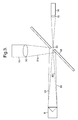
- FIG. 2 provides a schematic illustration of a tracker apparatus 13 in accordance with the present invention.
- the apparatus 13 incorporates a light source in the form of a laser 14 and a high-speed digital camera 15.
- the light source incorporates a lens 16 to project light towards a mirror 18 with an aperture 19.
- the camera 15 is associated with a filter and polariser combination 17 in order to appropriately present an image 20 to the camera 15.
- the laser 14 is associated an appropriate power source 21 whilst the camera 15 will be associated through a cable 22 with a controller whereby the images will be stored and compared as described later as well as provide for adjustment of the camera 15 made in order to achieve best results.
- the camera 15 is a high-speed digital camera with or without frame synchronised output.
- a high-speed shutter 23 may be used to improve image quality by opening and closing in conjunction with a pulsed light beam and thereby reducing background noise.
- the light source as indicated is normally a laser 14 which is divergent and may provide a continuous or pulsed light beam. Other laser types may be used to reduce back scatter. With laser choice dependant on wavelength and particle size.
- a light filter and polariser combination 17 is provided which matches with the laser wave length light source 14 as described above.
- targets in the form of retro reflectors 6 (figure 1) will be utilised in the present arrangement. These targets may be provided with a protective surface feature if required. Furthermore, where possible these targets may be designed for enhanced reflection at the wavelength of the light source 14.
- Camera images are relayed and stored in an appropriate storage facility of a controller for subsequent study. This may be through comparison of images. It may also be possible to provide determinations as to calculate fan orbit centre when it is difficult to find the centre of a rotating component. It should be appreciated that the retro-reflector 6 substantially reflects light back towards the light source, however a small angular deviation is necessary to avoid all the reflected light returning through the aperture 19 in mirror 18.
- an aperture 19 in the mirror 18 is preferred over a beam-splitter arrangement that could be placed in this position. This is due to the beam-splitter arrangement allowing a high level of background light to pass into the camera, which gives problems in separating the background laser light from the return laser light. Additionally the aperture in the mirror greatly aids maximising the light return from the retro-reflector to the camera. This is due to the return beam being slightly deviated by: a) lateral displacement of the return beam due to its path in the retro-reflector; b) diffraction caused by the finite aperture of the retro-reflector and the wavelength of light used and c) the imperfect build quality of the retro-reflector.
- the present arrangement allows identification of a rotating component orbit centre under very difficult, that is to say high light attenuation circumstances.
- a low divergence typically laser light signal, retro reflectors and the apertured mirror 18 it is possible to allow a high brightness signal to be captured by the camera 15 as the camera is not swamped and blinded by any scattered or background light.
- the present arrangement ensures a high signal to noise ratio over any background reflection or light signals from such sources as flames about a rotating component such as a blade assembly in a gas turbine engine.
- the centre of rotation is not accessible it is possible that multiple retro-reflectors will allow calculation of the rotating component dimensions by consideration of successive images received by the camera 15.
- accessibility is not a problem it may be possible to provide a situation where a single target in the form of a reflector could be fitted to the centre of the rotating component to act as a reference for image analysis.
- the retro reflected high intensity light beam from the laser 14 should be sufficient to overcome any large attenuation through dust or otherwise between the rotating component and the tracking apparatus.
- the targets 6 in accordance with the present invention are passive and will therefore not require a power source. In such circumstances the targets 6 will cause minimum additional weight and therefore will be less intrusive with regard to the results to be achieved.
- the use of several targets allows observation by image analysis and calculation of disc/object centres. As indicated previously through a known mathematical routine it is possible to calculate the centre of orbit of the rotating component. (If there are two or more known target positions).
- the mirror 18 is tilted and is generally at substantially forty-five degrees to the front of the rotating component. In such circumstances the light source laser 14 and camera 15 are then substantially in a perpendicular relationship about the aperture 19.
- the light source laser 14 and camera 15 are then substantially in a perpendicular relationship about the aperture 19.
- other optical angular presentations of the components may be achieved but will require active lens or other deflection mechanisms which may diminish light intensity particularly at optical interfaces and therefore capacity for high resolution.
- a beam splitter is not recommended for the reasons as hereinbefore described.
- the targets in the form of retro reflectors may be discrete components or specifically cut from a sheet of retro-reflective material and associated with the rotating component, or may even be for instance drilled bolt heads that perform the retro-reflection function.
- the light source laser may be continuous or pulsed to allow synchronisation to or with the camera in capturing images.
- the target is utilised in order to provide a reference within the image for comparison.
- the present arrangement can be utilised wherever there is a recognisable target feature for such image to image correlation.
- the arrangement has particular applicability where there is a poor transmissive medium such as through soot or dust or flame light signals, each of which are typical within a gas turbine engine, but where it is desirable to monitor a rotating component.
- the present arrangement has particular capability with respect to monitoring gas turbine engines either in prototype or service mode. Furthermore, as will be described later, it is possible to monitor these deflections relative to another reference such as a wing or fuselage position.
- the present arrangement has no direct contact with the rotating component and therefore can be considered non intrusive. If the centre of rotation is not directly available as the shaft exits on that centre of rotation the present arrangement may be used as an aid to shaft alignment. Furthermore, where a disc or partial disc has slid down a rotational shaft it will be appreciated that the present arrangement allows the position of the shaft centre to be found greatly aiding alignment of shafts in dirty or otherwise obscuring environments.
- Figure 3 provides a schematic illustration of the optical paths in accordance with the present arrangement. Consistent reference nomenclature to Figure 2 has been used for clarity.
- a light source 14 in the form of a laser is associated with the lens 16 in order to project an expanded light beam 30 towards a target retro reflector 6 ( Figure 1) and light is then reflected back along optical path 31 to become incident upon the mirror 18.
- the mirror 18 comprises a silvered plate such that the reflected light beam 31 is then deflected in the direction 31a to become incident upon the camera 15 through its lens 32.
- the camera 15 captures an image and this is stored as described above and used for comparison.
- the laser 14 may provide a continuous or pulsed light beam such that the camera 15 acquires images at different time periods as defined by a timer if the light beam is continuous or captures images for each light beam pulse from the laser 14.
- a single retro reflector is illustrated in Figure 3 but it would be appreciated that normally a rotating component will include a number of such reflectors to be deduced in the image captured by the camera 15 for analysis.
- an additional partial transmitting/reflective plate 40 may be placed at the entrance to a tracker apparatus 43. If the plate 40 is sufficiently tilted it can allow a reference target 45 to be observed coincidently with a retro reflected signal 44 from a rotating component 42. In such circumstances the reference point 45 will be shown in the image and utilised for reference with regard to other identifiable features in the image. It will be understood that the reference point should be accurately calibrated relative to the rotating component 42, but in any event will generally be stable in comparison with the rotating component 42. An example of utilisation of this refinement to the present arrangement would be to observe a position upon the ground adjacent the rotary component to ensure a reference for any observed movement in the rotatable component 42.
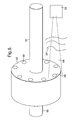
- a rotating component will have a number of targets or distinctive features in the form of retro reflectors.
- a rotating component 52 is secured upon a shaft 50 in order to rotate.
- a number of targets 56 are secured to the rotating component 52.
- a dusty environment 55 obscuring an image 54 received by a tracker apparatus 53 it will be understood that as the position of the targets 56 is known it will still be possible to identify movements and deflections in the shaft 58 in terms of centre of rotation for the rotating component 52 as well as with regard to other distortions provided these retro reflectors can still be identified in the image captured by the camera in the tracker apparatus 54.
- a shutter associated with the camera gives an advantage for the following reasons. When used with a pulsed light source it prevents the camera acquiring spurious and unnecessary light signals.
- the shutter being synchronised with the pulsed laser and or the camera.
- Such shutters may be any one of mechanical, electronic or as known to the skilled artisan. (see Figure 4).
- the rotating component in accordance with the present invention may be associated with targets such that movement of the rotating component to locate shaft centres as a function of axial position will not affect the ability of the monitoring arrangement to deduce displacements and distortions provided there is adequate reflection from the targets to allow capture of images by the camera. It will be understood that general operation of the present arrangement will ensure that the captured images from the camera are transferred to an appropriate controller and processor such that images can be compared in terms of position of targets and other distinct features in the rotating component in order to monitor that component.
- the present invention is also embodied by a method of calculating the co-ordinates of the centre of rotation of a body 2, 24 (such as the joined disc 2 and shaft 24 arrangement in figure 1) and thus an off-set between a body's 2, 24 rotational axis and its nominal central axis. This is particularly useful when the shaft 24 rotational axis itself is unobservable, for example when in use.
- An array of retro-reflectors 6 is placed on the disc 2, to which the shaft 24 is attached in known positions relative to the nominal physical rotational axis.
Abstract
Description
- The present invention relates to monitoring arrangements and more particularly to such monitoring arrangements utilised with regard to rotating components such as turbine blade assemblies in a gas turbine engine.
- It is important to be able to monitor components such as rotating blade assemblies in order to determine distortion and deflection in that component during operational use.
- It will be understood that rotating components will be subject to varying stresses and strains during use and therefore generally each of these components will distort and become displaced. A particular problem with respect to turbine blade assemblies in gas turbine engines is a so called blade-off situation where a blade becomes fully or partially detached or at least displaced causing rubbing with other components within the assembly. In such circumstances it is important to determine the varying distortions and displacements which precede such blade off situations in order that they can be avoided.
- Previously the main means of monitoring a rotating component has been by simple observation. Thus, a camera will be mounted in an appropriate position relative to the rotating component in order to record its motion and then through subsequent replaying and observation distortions and displacements noted in the rotating component. It will be understood in order to highlight distortions and displacements typically a high intensity laser or other illumination source has been used in order to give high brightness and a narrow bandwidth light response. In such circumstances utilising a specially modified high-speed digital camera that generally only accepts or is biased towards the laser light bandwidth and rejects the background light emitted background it is possible to improve the accuracy of observations.
- However, there are still particular problems from background or environmental light obscuring observations. This background light may be as a result of plasmas, arcs, flames and explosions typical in a gas turbine engine. It will also be understood that there may be dust or other particles which act as reflectors and so may further blind the camera in terms of its observational capacity.
- In view of the above previous methods are generally poor, and at least far from ideal, as it requires a high illumination level of light in order to indiscriminately penetrate the environmental pollution, that is to say, fog, dust, smoke, metallic and paint particles, soot, flames, water vapour, mist in the region in front of a rotating component such as a blade assembly in a gas turbine engine. However, a high illumination level can itself "blind" the camera by reflective light scatter from these particles. It would also be understood that there is lack of consistency in that the level of pollution which could cause camera blinding scatter may vary dependant upon operational state. In such circumstances it is not easy to provide any precision with regard to measuring displacement and distortion in the rotating component. Proposed attachment of high brightness devices to the rotating component will generally be unsatisfactory in that the device, that is to say a powered illumination source may be subject to breakage, provision of the device itself including its power supply will add to weight and therefore be intrusive with respect to a true response and may have limited effect upon the camera overall illumination.
- In accordance with the present invention there is provided a monitoring arrangement for a rotating component, the arrangement comprising a target for association with the rotating component and target tracking apparatus comprising a camera to track the target to identify variations in the target and so the rotating component and a light source to illuminate at least the target; the arrangement characterised in that the camera and the light source are associated with a mirror with an aperture such that light projects through the aperture towards the target in use and light is reflected back from the target towards the mirror in use and deflected towards the camera in use for localised discrimination by the camera from general light background.
- Typically, the mirror is arranged at forty-five degrees to the rotating component with the camera and the light source substantially perpendicular to each other about the aperture of the mirror. Normally, the mirror is a silvered or gold plate mirror.
- Typically, the camera is a high-speed digital camera. Normally, the camera is associated with a lens combination for focusing deflected light from the mirror from the camera. Additionally, the arrangement normally incorporates a polariser.
- Typically, the light source is a laser. Possibly, the light source is a high brightness narrow bandwidth laser. Possibly the light source has a specific wavelength for facilitating discrimination by the camera.
- Possibly, the target is optically active. Advantageously the target is a retro reflector. Generally, the target will comprise a number of target elements for distribution about a component. Possibly, the target is a distinguishable feature in the rotating component.
- Accordingly, another aspect of the present invention is a method of finding the off-set between a body's rotational axis and its nominal central axis, the body has disposed thereon at least two targets in known locations, the method comprising the steps of (a) rotating the body, (b) detecting the location of the two targets via a monitoring arrangement as described above, and (c) calculating the location of the rotational axis.
- Preferably, the method comprises step (d) where the body is balanced by either adding or removing a mass to the assembly.
- Preferably, the method includes the further step of repeating steps (a) - (c) to ensure the rotational axis and central axis of the body are coincident.
- Embodiments of the present invention will now be described by way of example and with reference to the accompanying drawings in which:-
- Figure 1 is a schematic illustration of a monitoring arrangement in accordance with the present invention;
- Figure 2 is a schematic illustration of a target tracking arrangement in accordance with the present invention;
- Figure 3 is a schematic illustration showing light paths in accordance with the present invention;
- Figure 4 schematic illustration of a refinement to the present monitoring arrangement incorporating a reference point or area; and,
- Figure 5 is a schematic illustration of a further refinement of the monitoring arrangement described above.
- It is desirable to be able to monitor and review rotating components such as discs, hubs and fan blades within a gas turbine engine in order to denote variations in terms of displacement and distortion of the respective blades, discs or other parts within the component or the component itself.
- Figure 1 provides a schematic illustration of a monitoring arrangement 1 in accordance with the present invention. Thus, a rotating component such as a fan disc 2 is viewed by a
tracking apparatus 3 with animage 4 received from the component 2 through partial obscuration as a result of dust, flames light scatter etc. This partial obscuration is shown by lines 5 in Figure 1. In order to enhance the accuracy of tracking typically targets in the form ofretro reflectors 6 are secured to the rotating component 2. - The
tracking apparatus 3 monitors the rotating component 2 and generatesimages 4 which are compared to determine variations in displacement as the components are subject to various operational conditions. This monitoring of the component 2 as indicated can be during prototyping and design stages for a machine incorporating the rotating components such as illustrated within a gas turbine engine incorporating the fan blades in an arrangement and a rotating component 2 depicted in Figure 1. The clearer and more accurately the component 2 can be viewed the better the monitoring of that component. As indicated previously simply increasing light intensity is not appropriate as this may through polluting particles increase light scatter and the back ground light and therefore effectively blind the camera utilised within thetracking apparatus 3. - Figure 2 provides a schematic illustration of a tracker apparatus 13 in accordance with the present invention. Thus, the apparatus 13 incorporates a light source in the form of a
laser 14 and a high-speeddigital camera 15. The light source incorporates alens 16 to project light towards amirror 18 with anaperture 19. Thecamera 15 is associated with a filter andpolariser combination 17 in order to appropriately present animage 20 to thecamera 15. It will also be understood that thelaser 14 is associated anappropriate power source 21 whilst thecamera 15 will be associated through acable 22 with a controller whereby the images will be stored and compared as described later as well as provide for adjustment of thecamera 15 made in order to achieve best results. Generally thecamera 15 is a high-speed digital camera with or without frame synchronised output. Additionally, a high-speed shutter 23 may be used to improve image quality by opening and closing in conjunction with a pulsed light beam and thereby reducing background noise. The light source as indicated is normally alaser 14 which is divergent and may provide a continuous or pulsed light beam. Other laser types may be used to reduce back scatter. With laser choice dependant on wavelength and particle size. In a preferred embodiment, as indicated a light filter andpolariser combination 17 is provided which matches with the laser wavelength light source 14 as described above. As indicated previously in order to enhance discrimination from background typically targets in the form of retro reflectors 6 (figure 1) will be utilised in the present arrangement. These targets may be provided with a protective surface feature if required. Furthermore, where possible these targets may be designed for enhanced reflection at the wavelength of thelight source 14. Camera images are relayed and stored in an appropriate storage facility of a controller for subsequent study. This may be through comparison of images. It may also be possible to provide determinations as to calculate fan orbit centre when it is difficult to find the centre of a rotating component. It should be appreciated that the retro-reflector 6 substantially reflects light back towards the light source, however a small angular deviation is necessary to avoid all the reflected light returning through theaperture 19 inmirror 18. - The use of an
aperture 19 in themirror 18 is preferred over a beam-splitter arrangement that could be placed in this position. This is due to the beam-splitter arrangement allowing a high level of background light to pass into the camera, which gives problems in separating the background laser light from the return laser light. Additionally the aperture in the mirror greatly aids maximising the light return from the retro-reflector to the camera. This is due to the return beam being slightly deviated by: a) lateral displacement of the return beam due to its path in the retro-reflector; b) diffraction caused by the finite aperture of the retro-reflector and the wavelength of light used and c) the imperfect build quality of the retro-reflector. This leads to the return of a high proportion of the light emitted by the laser being returned to a region around the aperture in the mirror and thereon being reflected towards the camera. If it where not for these deviations then the return signal would pass back down the aperture and no light signal from the retro-reflector would be detected. The overall effect being that there appears to be very high brightness light sources emanating from the object. - In general operation in accordance with the present arrangement light is emitted from the
light source laser 14 and passes through theaperture hole 19 in themirror 18 tilted appropriately. On account of the expansion caused by a lens in front of thelaser 14, a patch of light shown by firstbroken line 11 is incident upon the rotating component, that is to say a fan blade assembly. This incident light is reflected typically at least from the target reflectors 6 (Figure 1). The reflected light impinges upon the mirrored surface of themirror 18 and in deflected towards thecamera 15. The deflected light enters the lens of the camera and is focused on an image detector. The images from the detector are stored in an appropriate controller as described later until such a time as they can be analysed. Analysis consists partly of a mathematical routine to extract the co-ordinates of the points of interest, i.e. the known feature positions, and relate them to the centre of orbit of the subject rotating component. - The present arrangement allows identification of a rotating component orbit centre under very difficult, that is to say high light attenuation circumstances. By the effective use of a low divergence typically laser light signal, retro reflectors and the
apertured mirror 18, it is possible to allow a high brightness signal to be captured by thecamera 15 as the camera is not swamped and blinded by any scattered or background light. By such provision the present arrangement ensures a high signal to noise ratio over any background reflection or light signals from such sources as flames about a rotating component such as a blade assembly in a gas turbine engine. - In situations where the centre of rotation is not accessible it is possible that multiple retro-reflectors will allow calculation of the rotating component dimensions by consideration of successive images received by the
camera 15. However where accessibility is not a problem it may be possible to provide a situation where a single target in the form of a reflector could be fitted to the centre of the rotating component to act as a reference for image analysis. It will be understood that the retro reflected high intensity light beam from thelaser 14 should be sufficient to overcome any large attenuation through dust or otherwise between the rotating component and the tracking apparatus. It will be understood that thetargets 6 in accordance with the present invention are passive and will therefore not require a power source. In such circumstances thetargets 6 will cause minimum additional weight and therefore will be less intrusive with regard to the results to be achieved. The use of several targets allows observation by image analysis and calculation of disc/object centres. As indicated previously through a known mathematical routine it is possible to calculate the centre of orbit of the rotating component. (If there are two or more known target positions). - As indicated above light from
laser 14 is projected through theaperture 19 towards a rotating component in a beam defined by firstbroken lines 11. Some reflected light from the rotating component and from at least two of the targets, that is to say retro-reflectors 6 is returned to the tracking apparatus 13 along the path defined by secondbroken line 12. This reflected light 12 is itself reflected and deflected by themirror 18 towards thecamera 15 through the filter andpolariser combination 17. The image is then recorded by thecamera 15 and stored appropriately. - The
mirror 18 is tilted and is generally at substantially forty-five degrees to the front of the rotating component. In such circumstances thelight source laser 14 andcamera 15 are then substantially in a perpendicular relationship about theaperture 19. Clearly, other optical angular presentations of the components may be achieved but will require active lens or other deflection mechanisms which may diminish light intensity particularly at optical interfaces and therefore capacity for high resolution. A beam splitter is not recommended for the reasons as hereinbefore described. - By use of the
mirror 18 and normally the filter/polariser combination 17, it will be appreciated that local discrimination with regard to the image is achieved such that light scatter will not blind or over-expose the camera in terms of sensitivity or resolution. - The targets in the form of retro reflectors may be discrete components or specifically cut from a sheet of retro-reflective material and associated with the rotating component, or may even be for instance drilled bolt heads that perform the retro-reflection function. As indicated the light source laser may be continuous or pulsed to allow synchronisation to or with the camera in capturing images.
- As indicated above in accordance with the present arrangement the target is utilised in order to provide a reference within the image for comparison. In such circumstances the present arrangement can be utilised wherever there is a recognisable target feature for such image to image correlation. The arrangement has particular applicability where there is a poor transmissive medium such as through soot or dust or flame light signals, each of which are typical within a gas turbine engine, but where it is desirable to monitor a rotating component. In such circumstances the present arrangement has particular capability with respect to monitoring gas turbine engines either in prototype or service mode. Furthermore, as will be described later, it is possible to monitor these deflections relative to another reference such as a wing or fuselage position. Additionally, where multiple targets are available and used as indicated above it is possible to monitor wheel rotation, on or off axis, as the centre of rotation of the rotation device and deflection from the expected rotational centre and this can be utilised in order to determine the deflection on aircraft or road vehicles for either safety or design data assessment.
- The present arrangement has no direct contact with the rotating component and therefore can be considered non intrusive. If the centre of rotation is not directly available as the shaft exits on that centre of rotation the present arrangement may be used as an aid to shaft alignment. Furthermore, where a disc or partial disc has slid down a rotational shaft it will be appreciated that the present arrangement allows the position of the shaft centre to be found greatly aiding alignment of shafts in dirty or otherwise obscuring environments.
- Figure 3 provides a schematic illustration of the optical paths in accordance with the present arrangement. Consistent reference nomenclature to Figure 2 has been used for clarity. Thus, a
light source 14 in the form of a laser is associated with thelens 16 in order to project an expandedlight beam 30 towards a target retro reflector 6 (Figure 1) and light is then reflected back alongoptical path 31 to become incident upon themirror 18. Themirror 18 comprises a silvered plate such that the reflectedlight beam 31 is then deflected in thedirection 31a to become incident upon thecamera 15 through itslens 32. Thecamera 15 captures an image and this is stored as described above and used for comparison. Thelaser 14 may provide a continuous or pulsed light beam such that thecamera 15 acquires images at different time periods as defined by a timer if the light beam is continuous or captures images for each light beam pulse from thelaser 14. A single retro reflector is illustrated in Figure 3 but it would be appreciated that normally a rotating component will include a number of such reflectors to be deduced in the image captured by thecamera 15 for analysis. - As indicated above where a centre of rotation cannot be utilised as a reference alternatives may be used. Thus, as illustrated in Figure 4, an additional partial transmitting/
reflective plate 40 may be placed at the entrance to atracker apparatus 43. If theplate 40 is sufficiently tilted it can allow areference target 45 to be observed coincidently with a retro reflectedsignal 44 from a rotatingcomponent 42. In such circumstances thereference point 45 will be shown in the image and utilised for reference with regard to other identifiable features in the image. It will be understood that the reference point should be accurately calibrated relative to therotating component 42, but in any event will generally be stable in comparison with the rotatingcomponent 42. An example of utilisation of this refinement to the present arrangement would be to observe a position upon the ground adjacent the rotary component to ensure a reference for any observed movement in therotatable component 42. - As indicated above generally a rotating component will have a number of targets or distinctive features in the form of retro reflectors. Thus, as illustrated in Fig. 5, a rotating
component 52 is secured upon ashaft 50 in order to rotate. A number oftargets 56 are secured to therotating component 52. Thus, if there is adusty environment 55 obscuring animage 54 received by a tracker apparatus 53 it will be understood that as the position of thetargets 56 is known it will still be possible to identify movements and deflections in the shaft 58 in terms of centre of rotation for therotating component 52 as well as with regard to other distortions provided these retro reflectors can still be identified in the image captured by the camera in thetracker apparatus 54. - A shutter associated with the camera gives an advantage for the following reasons. When used with a pulsed light source it prevents the camera acquiring spurious and unnecessary light signals. The shutter being synchronised with the pulsed laser and or the camera. Such shutters may be any one of mechanical, electronic or as known to the skilled artisan. (see Figure 4).
- Modifications and alterations to the present monitoring arrangement will be understood by those skilled in the art. Thus it will be appreciated that the rotating component in accordance with the present invention may be associated with targets such that movement of the rotating component to locate shaft centres as a function of axial position will not affect the ability of the monitoring arrangement to deduce displacements and distortions provided there is adequate reflection from the targets to allow capture of images by the camera. It will be understood that general operation of the present arrangement will ensure that the captured images from the camera are transferred to an appropriate controller and processor such that images can be compared in terms of position of targets and other distinct features in the rotating component in order to monitor that component.
- The present invention is also embodied by a method of calculating the co-ordinates of the centre of rotation of a body 2, 24 (such as the joined disc 2 and
shaft 24 arrangement in figure 1) and thus an off-set between a body's 2, 24 rotational axis and its nominal central axis. This is particularly useful when theshaft 24 rotational axis itself is unobservable, for example when in use. An array of retro-reflectors 6 is placed on the disc 2, to which theshaft 24 is attached in known positions relative to the nominal physical rotational axis. In this example if at least two retro-reflector 6 positions are known and the angle between them is known (about the nominal physical central axis of the shaft 24) then by simple trigonometry and knowledge of the radii lengths a position in terms of x and y co-ordinates can be found for the centre of rotation by solving a quadratic equation. The x and y coordinates are relative to the bottom left hand side of the camera image but any notional datum or reference position may be used. - Thus before rotation the position of the nominal physical axis of the disc/shaft is known; then during operation, the disc/shaft rotates about an actual rotational axis which is then observed by the monitoring arrangement as hereinbefore described, and the new locations of the two retro-reflectors can be measured and using simple trigonometry the centre of rotation of the shaft may be calculated. This method is therefore useful for balancing rotor assemblies, the method further comprising balancing the rotor by either adding or removing a mass to the assembly and re-calculating the centre of rotation. Other known methods of balancing may be used.
- Knowing the centre of rotation and in association with time data it is possible to ascertain the accelerations and hence loads imposed on the structure of the engine and to determine what loads are passed through to the pylon/wing.
Claims (18)
- A monitoring arrangement (1) for a rotating component, the arrangement comprising a target (6) for association with the rotating component (2) and target tracking apparatus (3,13) comprising a camera to track the target to identify variations in the target and so the rotating component and a light source (14) to illuminate at least the target; the arrangement characterised in that the camera and the light source are associated with a mirror (18) with an aperture (19) such that light projects though the aperture towards the target in use and light is reflected back from the target towards the mirror in use and deflected towards the camera in use for localised discrimination by the camera from general light background.
- An arrangement as claimed in claim 1 wherein the mirror is arranged at forty-five degrees to the rotating component with the camera and the light source substantially perpendicular to each other about the aperture of the mirror.
- An arrangement as claimed in claim 1 or claim 2 wherein the mirror is any one of the group comprising silvered or gold plate mirror.
- An arrangement as claimed in claim 1 or claim 2 or claim 3 wherein the camera is a high-speed digital camera.
- An arrangement as claimed in the preceding claim wherein the camera is associated with a lens combination (17) for focusing deflected light from the mirror from the camera.
- An arrangement as claimed in the preceding claim wherein the arrangement normally incorporates a polariser.
- An arrangement as claimed in the preceding claim wherein the light source is a laser.
- An arrangement as claimed in claim 7 wherein the light source is a high brightness narrow bandwidth laser.
- An arrangement as claimed in the preceding claim wherein the light source has a specific wavelength for facilitating discrimination by the camera.
- An arrangement as claimed in the preceding claim wherein the target is optically active.
- An arrangement as claimed in the claim 10 wherein the target is a retro reflector.
- An arrangement as claimed in the preceding claim wherein the target will comprise a number of target elements for distribution about a rotating component.
- An arrangement as claimed in the preceding claim wherein the target comprises an identifiable feature in a subject rotating component.
- A gas turbine engine associated with a monitoring arrangement for monitoring a rotating component within the gas turbine engine, the monitoring arrangement being as claimed in any preceding claim.
- An engine as claimed in claim 14 wherein the rotating component is a turbine blade assembly.
- A method of finding the off-set between a body's (2, 24) rotational axis and its nominal central axis, the body (2, 24) has disposed thereon at least two targets (6) in known locations, the method comprising the steps of (a) rotating the body (2, 24), (b) detecting the location of the two targets (6) via a monitoring arrangement (1) of claim 1, and (c) calculating the location of the rotational axis.
- A method according to claim 16 wherein the method comprises step (d) where the body (2, 24) is balanced by either adding or removing a mass to the assembly.
- A method according to claim 17 wherein the method includes the further step of repeating steps (a) - (c) to ensure the rotational axis and central axis of the body are coincident.
Applications Claiming Priority (1)
| Application Number | Priority Date | Filing Date | Title |
|---|---|---|---|
| GBGB0514108.0A GB0514108D0 (en) | 2005-07-08 | 2005-07-08 | A monitoring arrangement |
Publications (3)
| Publication Number | Publication Date |
|---|---|
| EP1742017A2 true EP1742017A2 (en) | 2007-01-10 |
| EP1742017A3 EP1742017A3 (en) | 2007-01-17 |
| EP1742017B1 EP1742017B1 (en) | 2007-08-29 |
Family
ID=34896978
Family Applications (1)
| Application Number | Title | Priority Date | Filing Date |
|---|---|---|---|
| EP06252996A Expired - Fee Related EP1742017B1 (en) | 2005-07-08 | 2006-06-09 | A method of finding the off-set between a body's rotational axis and its nominal axis |
Country Status (4)
| Country | Link |
|---|---|
| US (1) | US7502128B2 (en) |
| EP (1) | EP1742017B1 (en) |
| DE (1) | DE602006000089T2 (en) |
| GB (1) | GB0514108D0 (en) |
Cited By (3)
| Publication number | Priority date | Publication date | Assignee | Title |
|---|---|---|---|---|
| DE102008024395A1 (en) * | 2008-05-20 | 2009-12-03 | Universität Karlsruhe (Th) | Method for object detection |
| GB2487931A (en) * | 2011-02-09 | 2012-08-15 | Rolls Royce Plc | Inspection of an engine component |
| CN104359866A (en) * | 2014-11-24 | 2015-02-18 | 杭州远方光电信息股份有限公司 | Retro-reflection measuring device |
Families Citing this family (3)
| Publication number | Priority date | Publication date | Assignee | Title |
|---|---|---|---|---|
| DE102009021557B4 (en) * | 2009-05-15 | 2016-08-04 | Airbus Defence and Space GmbH | Method for determining at least one movement quantity of a rotating shaft, wave examination and / or monitoring device for its implementation and use thereof |
| US9551620B2 (en) * | 2011-05-16 | 2017-01-24 | General Electric Company | Method and system for multi-functional embedded sensors |
| US10445871B2 (en) * | 2017-05-22 | 2019-10-15 | General Electric Company | Image analysis neural network systems |
Citations (6)
| Publication number | Priority date | Publication date | Assignee | Title |
|---|---|---|---|---|
| US4060329A (en) * | 1975-10-23 | 1977-11-29 | General Electric Company | Method and apparatus for measuring deflection of rotating airfoils |
| GB2178165A (en) * | 1985-07-24 | 1987-02-04 | Rolls Royce Plc | Optical monitoring method and apparatus |
| US5017796A (en) * | 1989-01-11 | 1991-05-21 | Mitsubishi Jukogyo Kabushiki Kaisha | Moving blade tip clearance measurement apparatus and method with moveable lens |
| WO1992022784A1 (en) * | 1991-06-13 | 1992-12-23 | Prüftechnik Dieter Busch AG | Process and device for determining the centre-line of a cuvrature |
| JPH0861917A (en) * | 1994-08-18 | 1996-03-08 | S K S Kk | Position detecting device |
| WO2000008415A1 (en) * | 1998-08-05 | 2000-02-17 | Cadent Ltd. | Imaging a three-dimensional structure by confocal focussing an array of light beams |
Family Cites Families (4)
| Publication number | Priority date | Publication date | Assignee | Title |
|---|---|---|---|---|
| US4334777A (en) | 1976-07-26 | 1982-06-15 | Aerodyne Research, Inc. | Method of monitoring motion |
| US4086808A (en) | 1976-07-26 | 1978-05-02 | Aerodyne Research, Inc. | Motion detection and measurement |
| US4080823A (en) * | 1976-11-05 | 1978-03-28 | United Technologies Corporation | Vibration measurement |
| JPS56111407A (en) | 1980-02-08 | 1981-09-03 | Toshiba Corp | Shaft torsion detecting method |
-
2005
- 2005-07-08 GB GBGB0514108.0A patent/GB0514108D0/en not_active Ceased
-
2006
- 2006-06-09 DE DE602006000089T patent/DE602006000089T2/en active Active
- 2006-06-09 EP EP06252996A patent/EP1742017B1/en not_active Expired - Fee Related
- 2006-06-12 US US11/450,335 patent/US7502128B2/en active Active
Patent Citations (6)
| Publication number | Priority date | Publication date | Assignee | Title |
|---|---|---|---|---|
| US4060329A (en) * | 1975-10-23 | 1977-11-29 | General Electric Company | Method and apparatus for measuring deflection of rotating airfoils |
| GB2178165A (en) * | 1985-07-24 | 1987-02-04 | Rolls Royce Plc | Optical monitoring method and apparatus |
| US5017796A (en) * | 1989-01-11 | 1991-05-21 | Mitsubishi Jukogyo Kabushiki Kaisha | Moving blade tip clearance measurement apparatus and method with moveable lens |
| WO1992022784A1 (en) * | 1991-06-13 | 1992-12-23 | Prüftechnik Dieter Busch AG | Process and device for determining the centre-line of a cuvrature |
| JPH0861917A (en) * | 1994-08-18 | 1996-03-08 | S K S Kk | Position detecting device |
| WO2000008415A1 (en) * | 1998-08-05 | 2000-02-17 | Cadent Ltd. | Imaging a three-dimensional structure by confocal focussing an array of light beams |
Cited By (3)
| Publication number | Priority date | Publication date | Assignee | Title |
|---|---|---|---|---|
| DE102008024395A1 (en) * | 2008-05-20 | 2009-12-03 | Universität Karlsruhe (Th) | Method for object detection |
| GB2487931A (en) * | 2011-02-09 | 2012-08-15 | Rolls Royce Plc | Inspection of an engine component |
| CN104359866A (en) * | 2014-11-24 | 2015-02-18 | 杭州远方光电信息股份有限公司 | Retro-reflection measuring device |
Also Published As
| Publication number | Publication date |
|---|---|
| DE602006000089D1 (en) | 2007-10-11 |
| US20070009252A1 (en) | 2007-01-11 |
| EP1742017A3 (en) | 2007-01-17 |
| GB0514108D0 (en) | 2005-08-17 |
| US7502128B2 (en) | 2009-03-10 |
| EP1742017B1 (en) | 2007-08-29 |
| DE602006000089T2 (en) | 2008-01-03 |
Similar Documents
| Publication | Publication Date | Title |
|---|---|---|
| US7502128B2 (en) | Monitoring arrangement for rotating components | |
| CN103975250B (en) | The spatial selectivity utilizing dynamic mask in the plane of delineation detects | |
| EP1582854B1 (en) | System and method for the measurement of optical distortions | |
| US20020180987A1 (en) | Profiling of a component having reduced sensitivity to anomalous off-axis reflections | |
| EP2304391B1 (en) | Optical device and method for measuring the rotation of an object | |
| US20090213359A1 (en) | Optical device for measuring moving speed of an object relative to a surface | |
| NO890430L (en) | PROCEDURE AND APPARATUS FOR MEASURING INSIGHT RATING FOR ELECTRICAL AND OPTICAL SYSTEMS. | |
| US4049336A (en) | Pulsed holographic system having independent universal beam adjustment | |
| US7206066B2 (en) | Reflectance surface analyzer | |
| CN103376265A (en) | Object defect check system and method | |
| US5311287A (en) | Direct access storage device with head-disc dynamics monitor | |
| US7443518B2 (en) | Measuring instrument, in particular for transmission measurement in vacuum system | |
| JPH07502810A (en) | Method and apparatus for measuring the slope of an interface in an optical system | |
| EP0731335B1 (en) | Apparatus and method for non destructive testing of coherent radiation illuminated material | |
| EP3111188B1 (en) | Optical instrument for identifying and locating micro-etching on an ophthalmic lens | |
| JPH06341919A (en) | Analytical experiment device for wing ambient flow | |
| ES2883932T3 (en) | Optical measurement of surface roughness | |
| JP4255586B2 (en) | Sample inspection equipment | |
| TWI386619B (en) | Method and equipment for measuring a rotating object | |
| US3993399A (en) | Universal holographic optics orientation assembly | |
| JP2005106820A (en) | Coordinated polarization for shiny surface measurement | |
| FR2972051A1 (en) | SIMPLIFIED CONTROL BENCH OF SELF-CONTROLLED TELESCOPES AND TELESCOPES | |
| JPH09113211A (en) | Interferometer with noise preventing function | |
| US7964834B2 (en) | Low backscatter test method and apparatus | |
| US20210096256A1 (en) | Integrated device for laser ranging and imaging |
Legal Events
| Date | Code | Title | Description |
|---|---|---|---|
| PUAI | Public reference made under article 153(3) epc to a published international application that has entered the european phase |
Free format text: ORIGINAL CODE: 0009012 |
|
| PUAL | Search report despatched |
Free format text: ORIGINAL CODE: 0009013 |
|
| AK | Designated contracting states |
Kind code of ref document: A2 Designated state(s): AT BE BG CH CY CZ DE DK EE ES FI FR GB GR HU IE IS IT LI LT LU LV MC NL PL PT RO SE SI SK TR |
|
| AX | Request for extension of the european patent |
Extension state: AL BA HR MK YU |
|
| AK | Designated contracting states |
Kind code of ref document: A3 Designated state(s): AT BE BG CH CY CZ DE DK EE ES FI FR GB GR HU IE IS IT LI LT LU LV MC NL PL PT RO SE SI SK TR |
|
| AX | Request for extension of the european patent |
Extension state: AL BA HR MK YU |
|
| RIC1 | Information provided on ipc code assigned before grant |
Ipc: G01B 11/16 20060101ALI20061213BHEP Ipc: G01B 11/27 20060101AFI20061026BHEP |
|
| 17P | Request for examination filed |
Effective date: 20061229 |
|
| 17Q | First examination report despatched |
Effective date: 20070226 |
|
| GRAP | Despatch of communication of intention to grant a patent |
Free format text: ORIGINAL CODE: EPIDOSNIGR1 |
|
| RTI1 | Title (correction) |
Free format text: A METHOD OF FINDING THE OFF-SET BETWEEN A BODY'S ROTATIONAL AXIS AND ITS NOMINAL AXIS |
|
| GRAS | Grant fee paid |
Free format text: ORIGINAL CODE: EPIDOSNIGR3 |
|
| GRAA | (expected) grant |
Free format text: ORIGINAL CODE: 0009210 |
|
| AK | Designated contracting states |
Kind code of ref document: B1 Designated state(s): DE FR GB |
|
| REG | Reference to a national code |
Ref country code: GB Ref legal event code: FG4D |
|
| AKX | Designation fees paid |
Designated state(s): DE FR GB |
|
| REF | Corresponds to: |
Ref document number: 602006000089 Country of ref document: DE Date of ref document: 20071011 Kind code of ref document: P |
|
| ET | Fr: translation filed | ||
| PLBE | No opposition filed within time limit |
Free format text: ORIGINAL CODE: 0009261 |
|
| STAA | Information on the status of an ep patent application or granted ep patent |
Free format text: STATUS: NO OPPOSITION FILED WITHIN TIME LIMIT |
|
| 26N | No opposition filed |
Effective date: 20080530 |
|
| REG | Reference to a national code |
Ref country code: FR Ref legal event code: PLFP Year of fee payment: 10 |
|
| REG | Reference to a national code |
Ref country code: FR Ref legal event code: PLFP Year of fee payment: 11 |
|
| REG | Reference to a national code |
Ref country code: FR Ref legal event code: PLFP Year of fee payment: 12 |
|
| REG | Reference to a national code |
Ref country code: FR Ref legal event code: PLFP Year of fee payment: 13 |
|
| PGFP | Annual fee paid to national office [announced via postgrant information from national office to epo] |
Ref country code: FR Payment date: 20200626 Year of fee payment: 15 |
|
| PGFP | Annual fee paid to national office [announced via postgrant information from national office to epo] |
Ref country code: GB Payment date: 20200629 Year of fee payment: 15 |
|
| PGFP | Annual fee paid to national office [announced via postgrant information from national office to epo] |
Ref country code: DE Payment date: 20200827 Year of fee payment: 15 |
|
| REG | Reference to a national code |
Ref country code: DE Ref legal event code: R119 Ref document number: 602006000089 Country of ref document: DE |
|
| GBPC | Gb: european patent ceased through non-payment of renewal fee |
Effective date: 20210609 |
|
| PG25 | Lapsed in a contracting state [announced via postgrant information from national office to epo] |
Ref country code: GB Free format text: LAPSE BECAUSE OF NON-PAYMENT OF DUE FEES Effective date: 20210609 Ref country code: DE Free format text: LAPSE BECAUSE OF NON-PAYMENT OF DUE FEES Effective date: 20220101 |
|
| PG25 | Lapsed in a contracting state [announced via postgrant information from national office to epo] |
Ref country code: FR Free format text: LAPSE BECAUSE OF NON-PAYMENT OF DUE FEES Effective date: 20210630 |