EP1736193A1 - Inhaler - Google Patents
Inhaler Download PDFInfo
- Publication number
- EP1736193A1 EP1736193A1 EP06010290A EP06010290A EP1736193A1 EP 1736193 A1 EP1736193 A1 EP 1736193A1 EP 06010290 A EP06010290 A EP 06010290A EP 06010290 A EP06010290 A EP 06010290A EP 1736193 A1 EP1736193 A1 EP 1736193A1
- Authority
- EP
- European Patent Office
- Prior art keywords
- inhalation therapy
- aerosol
- gaseous medium
- therapy device
- supply
- Prior art date
- Legal status (The legal status is an assumption and is not a legal conclusion. Google has not performed a legal analysis and makes no representation as to the accuracy of the status listed.)
- Granted
Links
Images

Classifications
-
- A—HUMAN NECESSITIES
- A61—MEDICAL OR VETERINARY SCIENCE; HYGIENE
- A61M—DEVICES FOR INTRODUCING MEDIA INTO, OR ONTO, THE BODY; DEVICES FOR TRANSDUCING BODY MEDIA OR FOR TAKING MEDIA FROM THE BODY; DEVICES FOR PRODUCING OR ENDING SLEEP OR STUPOR
- A61M15/00—Inhalators
- A61M15/0085—Inhalators using ultrasonics
-
- A—HUMAN NECESSITIES
- A61—MEDICAL OR VETERINARY SCIENCE; HYGIENE
- A61M—DEVICES FOR INTRODUCING MEDIA INTO, OR ONTO, THE BODY; DEVICES FOR TRANSDUCING BODY MEDIA OR FOR TAKING MEDIA FROM THE BODY; DEVICES FOR PRODUCING OR ENDING SLEEP OR STUPOR
- A61M11/00—Sprayers or atomisers specially adapted for therapeutic purposes
- A61M11/02—Sprayers or atomisers specially adapted for therapeutic purposes operated by air or other gas pressure applied to the liquid or other product to be sprayed or atomised
-
- A—HUMAN NECESSITIES
- A61—MEDICAL OR VETERINARY SCIENCE; HYGIENE
- A61M—DEVICES FOR INTRODUCING MEDIA INTO, OR ONTO, THE BODY; DEVICES FOR TRANSDUCING BODY MEDIA OR FOR TAKING MEDIA FROM THE BODY; DEVICES FOR PRODUCING OR ENDING SLEEP OR STUPOR
- A61M15/00—Inhalators
- A61M15/0086—Inhalation chambers
-
- A—HUMAN NECESSITIES
- A61—MEDICAL OR VETERINARY SCIENCE; HYGIENE
- A61M—DEVICES FOR INTRODUCING MEDIA INTO, OR ONTO, THE BODY; DEVICES FOR TRANSDUCING BODY MEDIA OR FOR TAKING MEDIA FROM THE BODY; DEVICES FOR PRODUCING OR ENDING SLEEP OR STUPOR
- A61M16/00—Devices for influencing the respiratory system of patients by gas treatment, e.g. mouth-to-mouth respiration; Tracheal tubes
- A61M16/08—Bellows; Connecting tubes ; Water traps; Patient circuits
- A61M16/0816—Joints or connectors
-
- A—HUMAN NECESSITIES
- A61—MEDICAL OR VETERINARY SCIENCE; HYGIENE
- A61M—DEVICES FOR INTRODUCING MEDIA INTO, OR ONTO, THE BODY; DEVICES FOR TRANSDUCING BODY MEDIA OR FOR TAKING MEDIA FROM THE BODY; DEVICES FOR PRODUCING OR ENDING SLEEP OR STUPOR
- A61M2206/00—Characteristics of a physical parameter; associated device therefor
- A61M2206/10—Flow characteristics
- A61M2206/14—Static flow deviators in tubes disturbing laminar flow in tubes, e.g. archimedes screws
Definitions
- the present invention relates to inhalation therapy devices that provide a patient with a medicament in the form of an aerosol for inhalation.
- aerosols are generated for therapeutic purposes, which must meet high demands.
- the requirements arise from the therapy to be performed with the inhalation therapy device.
- the aerosol generator At the heart of an inhalation therapy device is the aerosol generator, which generates an aerosol from a drug, which is regularly in the form of a liquid formulation or other fluid, when it is driven by an aerosol generation control unit provided in the inhalation therapy device.
- the aerosol generator has at least one membrane and a vibration generator, wherein the membrane can be vibrated by the vibration generator and then generates an aerosol from the medicament supplied to one side of the membrane, which is emitted on the other side of the membrane becomes.
- the resulting aerosol cloud expands in a space area in front of the aerosol generator, which is regularly used as a chamber in the space Housing of the inhalation therapy device is realized.
- the shape and size of the chamber are advantageously designed so that as few aerosol droplets / particles precipitate on the wall of the chamber.
- inhalation therapy devices in conjunction with ventilators in which a patient is ventilated or given a respiratory pattern via the supplied ventilation air is problematic in that the carefully matched generation and expansion of the aerosol cloud must be reconciled with the introduction of the aerosol into the aerosol ventilation air.
- a connecting device which comprises a T-shaped tube element that is inserted into the ventilation air line leading to the patient of a respiratory device.
- An aerosol generator is provided on the tube piece, which opens vertically into the tube piece which can be inserted into the ventilation air line, which generates an aerosol cloud which reaches the ventilation air via the opening of the tube.
- the design of the T-piece is not optimal in terms of flow, which leads to considerable aerosol and thus drug losses.
- T-shaped connections are also proposed to a respiratory line, via which an aerosol provided by an aerosol generator is introduced into the respiratory line. From DE 103 20 143 A
- known tees are designed much more effectively in terms of flow, since virtually the entire cross section of the tube piece opening into the ventilation line is available for the supply of the aerosol.
- the problem to be solved by the present invention is to provide an inhalation therapy device in which the generated aerosol and a gaseous medium, in particular air, are brought together in an advantageous manner and presented to a patient for inhalation.
- Another object of the present invention is to provide an inhalation therapy device which is particularly suitable for use in conjunction with a respiratory device.
- an inhalation therapy device comprises, in a preferred embodiment, an aerosol generating device designed to generate an aerosol from a medicament-containing liquid and to deliver the aerosol into an expansion space region, a liquid reservoir device suitable for the storage of the liquid and for the supply of the liquid the aerosol generating device is formed, a feed device, which is designed for the supply of a gaseous medium, in particular air, and a cylindrical pipe section, which is arranged around the expansion space region such that the supplied gaseous medium impinges on the outer jacket surface of the pipe section and at a front end flows into the interior of the pipe section.
- an inhalation therapy device comprises, in addition to the already mentioned aerosol generating device, liquid storage device and supply device, a flow influencing device which influences the flow path of the supplied gaseous medium such that the gaseous medium forms a sheath flow around the expansion space region for the aerosol.
- the sheath flow is to be understood as quasi-laminar flow of the gaseous medium in the areas at the edge of the expansion space area for the aerosol cloud.
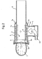
- FIGS. 1 and 2 show an inhalation therapy device according to the invention which has an aerosol generating device 1, for example a membrane aerosol generator.
- the aerosol generating device 1 generates an aerosol from a medicament-containing liquid or fluid, which discharges it into an expansion space region 2 in which the aerosol generated can expand.
- aerosol generation and delivery take place in the form of an aerosol cloud which expands to a certain extent and which expands from the aerosol generator 1 into the expansion region 2.
- the liquid to be atomized is stored in a liquid storage device 3, for example a liquid reservoir, and supplied to the aerosol generating device 1.
- a liquid storage device 3 for example a liquid reservoir
- the storage and supply of the liquid to be nebulised can be effected by separate means; however, the liquid storage device 3 shown in Figs. 1 and 2 which simultaneously serves to store and supply the liquid is preferable.
- the embodiment of an inhalation therapy device further comprises a supply device 4 for the supply of a gaseous medium, which is in particular air, a therapeutically effective gas or a suitable gas for the diagnosis.
- a gaseous medium which is in particular air, a therapeutically effective gas or a suitable gas for the diagnosis.
- the gaseous medium is supplied to the inhalation therapy device according to the invention, so that it is within the scope of the Inhalation therapy can be inhaled by a patient.
- the feeding device 4 is suitable in a particularly preferred embodiment of the first embodiment for the supply of the ventilation air of a respiratory device (not shown), which will not be further explained at this point, but which is basically known to those skilled in this field.
- the feeding device 4 is preferably designed for the supply of the entire breathing air, so that the air required for breathing via the supplied ventilation air to the patient via the feeding device 4 of the According to the inhalation therapy device according to the invention can be supplied.
- the aid of an inhalation therapy device according to the invention according to the first embodiment it is possible with the aid of an inhalation therapy device according to the invention according to the first embodiment to ventilate the patient or the patient to specify a breathing pattern, since all the air provided for the breathing air is supplied via the feeding device 4.
- the feed device 4 can be designed for the supply of ambient air, for example by opening to the environment.
- the active supply of the gaseous medium via the supply device 4 explained above with regard to a ventilation device is the preferred embodiment within the scope of the invention.
- the gaseous medium supplied via the supply device 4 encounters a flow influencing device 5.
- the flow profile of the supplied gaseous medium M is influenced by the flow influencing device 5 such that the gaseous medium M a sheath current m around the Expansion area 2 forms for the aerosol.
- the flow profile of the supplied gaseous medium M is indicated by way of example in FIG. 2 in the drawing plane. For this purpose, FIG.
- FIG. 2 shows a plurality of arrows which represent the supplied gaseous medium M which propagates around the flow influencing device 5 and flows around the flow influencing device 5 so that it finally flows along the edge of the expansion space region 2, in which the centrally emitted by the aerosol generator 1 Aerosol cloud spreads.
- the flow influencing device is realized in the form of a cylindrical tubular piece 5 which is arranged around the expansion space region 2.
- the aerosol cloud generated by the aerosol generator expands into the cylindrical tube piece 5.
- the cylindrical pipe section is circular in cross section, which is convenient and advantageous.
- the supplied gaseous medium M On the outside Mantle surface 5a of the blank 5 strikes the supplied gaseous medium M. It flows around the cylindrical tube piece 5 along the outer jacket surface 5 a, thereby expanding in the direction of the front end 5 b of the tube piece 5.
- the gaseous medium M is distributed essentially uniformly around the cylindrical tube piece 5 and reaches the front end 5b, which is arranged opposite the aerosol generator 1, so that the gaseous medium around the end face End 5b of the pipe section 5 flows around and continues to flow in the edge region of the expansion zone 2 of the aerosol cloud along the inner surface of the pipe section 5.
- the desired cylindrical sheath flow m forms around the expansion space region 2 for the aerosol.
- the tube piece 5 is advantageously formed in one piece with a mouthpiece 8 or a connecting piece for a breathing mask, via which the patient inhales the aerosol and the supplied gaseous medium.
- a connecting piece for a breathing mask resembles the one shown in the figure mouthpiece 8, so that an additional representation is unnecessary and can also be made with regard to the connection piece for a breathing mask to Figures 1 and 2.
- the patient is the mouthpiece 8 / the respiratory mask the entire breath to Provided. Due to the one-piece design of the pipe section 5 and the mouthpiece 8 / the connecting piece is achieved that a precipitation of the aerosol droplets / particles preventing mantle flow m is practically maintained up to the entrance into the mouth and throat of the patient.
- the cylindrical tube piece 5 is arranged in a chamber 6, into which the aerosol generator 1 emits the aerosol.
- the chamber 6 is enclosed by a portion 9 of the housing of the inhalation therapy device, wherein the housing portion 9, similar to the cylindrical tube piece 5, has a cylindrical, for example a circular cylindrical cross-section.
- this coordination between chamber 6 and pipe section 5 is not absolutely necessary in order to achieve the effect explained here. Because in any case is located between the inner wall 6a of the chamber 6 and the outer lateral surface 5a of the cylindrical pipe section 5, a gap 7 in which the supplied gaseous medium M can propagate.
- the gap 7 is closed off in a region 7 a arranged away from the aerosol generator 1, the propagation of the gaseous medium M takes place in the direction of the front end 5 b of the pipe section 5 which lies opposite the aerosol generator 1.
- the conclusion of the gap space 7 in the region 7a is preferably such that the housing 9 of the inhalation therapy device is integrally formed with the tube piece 5, as shown in Figures 1 and 2 for the illustrated embodiment.
- the inhalation therapy device furthermore results that the feed device for the gaseous medium M is preferably a cylindrical one Connecting piece 4 is provided on the housing 9 of the inhalation therapy device and opens to the chamber 6 out.
- the outlet opening 4a of the cylindrical connecting piece 4 is arranged so that it is aligned with the pipe section 5, so that this acts and deflecting the gaseous medium M.
- the cylindrical connecting piece 4 preferably has a circular cylindrical cross-section and is arranged centrally to the cylindrical pipe section 5.
- the connecting piece 4 may also be provided with a different cross section, for example an elliptical cross section, and / or arranged eccentrically to the pipe section 5.
- the feed device 4 has the embodiment shown also has a connection element 4b for the connection of a supply line, for example a hose.
- the gaseous medium M in particular the respiratory air from a respirator of the inhalation therapy device according to the invention, is supplied via the tube.
- the delivery device 4 also allows other types of airflows to be supplied, including, for example, the ambient air aspirated by an actively breathing patient entering the delivery device 4.
Abstract
Description
Die vorliegende Erfindung betrifft Inhalationstherapievorrichtungen, mit denen einem Patienten ein Medikament in Form eines Aerosols zur Einatmung bereitgestellt wird.The present invention relates to inhalation therapy devices that provide a patient with a medicament in the form of an aerosol for inhalation.
Mit Inhalationstherapievorrichtungen werden Aerosole für therapeutische Zwecke erzeugt, die hohen Anforderungen gerecht werden müssen. Die Anforderungen ergeben sich aus der Therapie, die mit der Inhalationstherapievorrichtung durchgeführt werden soll. Das Kernstück einer Inhalationstherapievorrichtung ist der Aerosolerzeuger, der aus einem Medikament, das regelmäßig in Form einer flüssigen Formulierung oder eines anderen Fluids vorliegt, ein Aerosol erzeugt, wenn er von einer in der Inhalationstherapievorrichtung vorhandenen Steuereinheit zur Aerosolerzeugung angesteuert wird. Der Aerosolerzeuger weist in einer vorteilhaften Ausgestaltung zumindest eine Membran und einen Schwingungserzeuger auf, wobei die Membran von dem Schwingungserzeuger in Schwingungen versetzt werden kann und dann aus dem an die eine Seite der Membran zugeführten Medikament ein Aerosol erzeugt, das auf der anderen Seite der Membran abgegeben wird. Die entstehende Aerosolwolke dehnt sich in einem vor dem Aerosolerzeuger befindlichen Raumbereich aus, der regelmäßig als eine Kammer in dem Gehäuse des Inhalationstherapiegeräts realisiert ist. Um Medikamentverluste zu minimieren, sind Form und Größe der Kammer vorteilhafterweise so ausgelegt, dass sich möglichst wenige Aerosoltröpfchen/-partikel an der Wand der Kammer niederschlagen.With inhalation therapy devices aerosols are generated for therapeutic purposes, which must meet high demands. The requirements arise from the therapy to be performed with the inhalation therapy device. At the heart of an inhalation therapy device is the aerosol generator, which generates an aerosol from a drug, which is regularly in the form of a liquid formulation or other fluid, when it is driven by an aerosol generation control unit provided in the inhalation therapy device. In an advantageous embodiment, the aerosol generator has at least one membrane and a vibration generator, wherein the membrane can be vibrated by the vibration generator and then generates an aerosol from the medicament supplied to one side of the membrane, which is emitted on the other side of the membrane becomes. The resulting aerosol cloud expands in a space area in front of the aerosol generator, which is regularly used as a chamber in the space Housing of the inhalation therapy device is realized. To minimize drug losses, the shape and size of the chamber are advantageously designed so that as few aerosol droplets / particles precipitate on the wall of the chamber.
Der Einsatz von Inhalationstherapiegeräten im Zusammenhang mit Beatmungsgeräten, bei denen ein Patient beatmet wird oder über die zugeführte Beatmungsluft ein Atemmuster vorgegeben erhält, ist insofern problematisch, als die sorgfältig abgestimmte Erzeugung und Ausdehnung der Aerosolwolke in Einklang gebracht werden muss mit der Einbringung des Aerosols in die Beatmungsluft.The use of inhalation therapy devices in conjunction with ventilators in which a patient is ventilated or given a respiratory pattern via the supplied ventilation air is problematic in that the carefully matched generation and expansion of the aerosol cloud must be reconciled with the introduction of the aerosol into the aerosol ventilation air.
Aus
Dennoch treten im Zusammenhang mit den bekannten T-Stücken für den Anschluss eines Inhalationstherapiegeräts an eine Beatmungsluftleitung eines Beatmungsgeräts immer wieder Aerosolverluste durch Niederschlagen von Aerosoltröpfchen/partikeln an verschiedenen Oberflächen auf.Nevertheless occur in connection with the known tees for the connection of an inhalation therapy device to a respiratory air line of a ventilator again and again Aerosol losses due to precipitation of aerosol droplets / particles on different surfaces.
Vor diesem Hintergrund besteht die von der vorliegenden Erfindung zu lösende Aufgabe darin, eine Inhalationstherapievorrichtung anzugeben, bei der das erzeugte Aerosol und ein gasförmiges Medium, insbesondere Luft auf vorteilhafte Weise zusammengebracht und einem Patienten zum Einatmen dargeboten werden.Against this background, the problem to be solved by the present invention is to provide an inhalation therapy device in which the generated aerosol and a gaseous medium, in particular air, are brought together in an advantageous manner and presented to a patient for inhalation.
Eine weitere Aufgabe der vorliegenden Erfindung besteht darin, eine Inhalationstherapievorrichtung anzugeben, die sich in besonderer Weise für den Einsatz im Zusammenhang mit einer Beatmungsvorrichtung eignet.Another object of the present invention is to provide an inhalation therapy device which is particularly suitable for use in conjunction with a respiratory device.
Diese und weitere Aufgaben werden gelöst durch eine Inhalationsvorrichtung mit den Merkmalen gemäß Anspruch 1 oder Anspruch 2. Vorteilhafte Ausgestaltungen ergeben sich aus den Unteransprüchen.These and other objects are achieved by an inhalation device having the features according to claim 1 or
Danach umfasst eine erfindungsgemäße Inhalationstherapievorrichtung in einer bevorzugten Ausführung eine Aerosolerzeugungseinrichtung, die für das Erzeugen eines Aerosols aus einer medikamenthaltigen Flüssigkeit und für die Abgabe des Aerosols in einen Ausdehnungsraumbereich ausgelegt ist, eine Flüssigkeitsbevorratungseinrichtung, die für die Bevorratung der Flüssigkeit und für die Zuführung der Flüssigkeit zu der Aerosolerzeugungseinrichtung ausgebildet ist, eine Zuführungseinrichtung, die für die Zuführung eines gasförmigen Mediums insbesondere Luft ausgebildet ist, und ein zylindrischen Rohrstück, das um den Ausdehnungsraumbereich derart angeordnet ist, dass das zugeführte gasförmige Medium auf die äußere Manteloberfläche des Rohrstücks auftrifft und an einem stirnseitigen Ende in das Innere des Rohrstücks strömt.Thereafter, an inhalation therapy device according to the invention comprises, in a preferred embodiment, an aerosol generating device designed to generate an aerosol from a medicament-containing liquid and to deliver the aerosol into an expansion space region, a liquid reservoir device suitable for the storage of the liquid and for the supply of the liquid the aerosol generating device is formed, a feed device, which is designed for the supply of a gaseous medium, in particular air, and a cylindrical pipe section, which is arranged around the expansion space region such that the supplied gaseous medium impinges on the outer jacket surface of the pipe section and at a front end flows into the interior of the pipe section.
Durch das Rohrstück wird auf effektive Weise eine Ab- und Umlenkung der Strömung des zugeführten gasförmigen Mediums erreicht. Über den Rand des stirnseitigen Endes tritt das gasförmige Medium in den Bereich ein, in dem sich die Aerosolwolke ausdehnt, die von dem Aerosolgenerator aus der bevorrateten Flüssigkeit erzeugt wird.Through the pipe section, a deflection and deflection of the flow of the supplied gaseous medium is achieved in an effective manner. Over the edge of the front end of the gaseous medium enters the area in which the aerosol cloud expands, which is generated by the aerosol generator from the stored liquid.
In einer verallgemeinerten Betrachtungsweise umfasst eine erfindungsgemäße Inhalationstherapievorrichtung neben der bereits zuvor erwähnten Aerosolerzeugungseinrichtung, Flüssigkeitsbevorratungseinrichtung und Zuführungseinrichtung eine Strömungsbeeinflussungseinrichtung, die den Strömungsverlauf des zugeführten gasförmigen Mediums beeinflussend derart ausgebildet ist, dass das gasförmige Medium einen Mantelstrom um den Ausdehnungsraumbereich für das Aerosol ausbildet.In a generalized view, an inhalation therapy device according to the invention comprises, in addition to the already mentioned aerosol generating device, liquid storage device and supply device, a flow influencing device which influences the flow path of the supplied gaseous medium such that the gaseous medium forms a sheath flow around the expansion space region for the aerosol.
Die Mantelströmung ist dabei als quasi-laminare Strömung des gasförmigen Mediums in den Bereichen am Rand des Ausdehnungsraumbereich für die Aerosolwolke zu verstehen.The sheath flow is to be understood as quasi-laminar flow of the gaseous medium in the areas at the edge of the expansion space area for the aerosol cloud.
Im Folgenden wird die Erfindung anhand von Ausführungsbeispielen unter Bezugnahme auf die beigefügten Zeichnungen genauer beschrieben. In den Zeichnungen zeigt:
- Figur 1
- eine geschnittene Seitenansicht eines ersten Ausführungsbeispiels einer erfindungsgemäßen Inhalationstherapievorrichtung; und
Figur 2- eine geschnittene Draufsicht auf das erste Ausführungsbeispiel einer erfindungsgemäßen Inhalationstherapievorrichtung.
- FIG. 1
- a sectional side view of a first embodiment of an inhalation therapy device according to the invention; and
- FIG. 2
- a sectional plan view of the first embodiment of an inhalation therapy device according to the invention.
Im Folgenden wird ein Ausführungsbeispiel einer Inhalationstherapievorrichtung gemäß der Erfindung anhand der Figuren 1 und 2 erläutert, die beide das erste Ausführungsbeispiel in einer geschnittenen Darstellung jedoch aus unterschiedlichen Blickrichtungen zeigen.In the following, an embodiment of an inhalation therapy device according to the invention with reference to Figures 1 and 2 is explained, both the first Embodiment in a sectional view, however, show from different directions.
In den Figuren 1 und 2 ist eine erfindungsgemäße Inhalationstherapievorrichtung dargestellt, die eine Aerosolerzeugungseinrichtung 1, beispielsweise einen Membran-Aerosolgenerator aufweist. Die Aerosolerzeugungseinrichtung 1 erzeugt aus einer medikamenthaltigen Flüssigkeit oder Fluid ein Aerosol, das sie in einen Ausdehnungsraumbereich 2 hinein abgibt, in dem sich das erzeugte Aerosol ausdehnen kann. Insbesondere bei Membran-Aerosolgeneratoren erfolgt die Aerosolerzeugung und Abgabe in Form einer sich in gewissem Umfang gerichtet ausdehnenden Aerosolwolke, die sich vom Aerosolgenerator 1 aus in den Ausdehnungsbereich 2 hinein ausdehnt.FIGS. 1 and 2 show an inhalation therapy device according to the invention which has an aerosol generating device 1, for example a membrane aerosol generator. The aerosol generating device 1 generates an aerosol from a medicament-containing liquid or fluid, which discharges it into an
Die zu vernebelnde Flüssigkeit wird in einer Flüssigkeitsbevorratungseinrichtung 3, beispielsweise einem Flüssigkeitsreservoir bevorratet und der Aerosolerzeugungseinrichtung 1 zugeführt. An dieser Stelle sei angemerkt, dass abweichend von dem in den Figuren 1 und 2 gezeigten Ausführungsbeispiel einer erfindungsgemäßen Inhalationstherapievorrichtung die Bevorratung und die Zuführung der zu vernebelnden Flüssigkeit durch getrennte Einrichtungen erfolgen kann; jedoch wird die in den Figuren 1 und 2 gezeigte Flüssigkeitsbevorratungseinrichtung 3 bevorzugt, die gleichzeitig der Bevorratung und Zuführung der Flüssigkeit dient.The liquid to be atomized is stored in a
Das Ausführungsbeispiel einer erfindungsgemäßen Inhalationstherapievorrichtung umfasst ferner eine Zuführungseinrichtung 4 für die Zuführung eines gasförmigen Mediums, bei dem es sich insbesondere um Luft, ein therapeutisch wirksames Gas oder ein für die Diagnostik geeignetes Gas handelt. Über die Zuführungseinrichtung 4 wird der erfindungsgemäßen Inhalationstherapievorrichtung das gasförmige Medium zugeführt, so dass es im Rahmen der Inhalationstherapie von einem Patienten eingeatmet werden kann. Die Zuführungseinrichtung 4 eignet sich in einer besonders bevorzugten Ausgestaltung des ersten Ausführungsbeispiels für die Zuführung der Beatmungsluft einer Beatmungsvorrichtung (nicht dargestellt), die an dieser Stelle nicht weiter erläutert werden soll, die aber dem in diesem Bereich tätigen Fachmann grundsätzlich bekannt ist. Jedoch ist für die Auslegung der erfindungsgemäßen Zuführungseinrichtung 4 in dieser besonderen Ausgestaltung zu beachten, dass dabei die Zuführungseinrichtung 4 vorzugsweise für die Zuführung der gesamten Atemluft ausgelegt ist, so dass über die zugeführte Beatmungsluft dem Patienten die für die Atmung erforderliche Luft über die Zuführungseinrichtung 4 der erfindungsgemäßen Inhalationstherapievorrichtung zugeführt werden kann. Auf diese Weise ist es möglich mit Hilfe einer erfindungsgemäßen Inhalationstherapievorrichtung gemäß dem ersten Ausführungsbeispiel den Patienten zu beatmen oder dem Patienten ein Atemmuster vorzugeben, da die gesamte für die Atmung bereitgestellte Luft über die Zuführungseinrichtung 4 zugeführt wird. Sofern keine Beatmungsluft aus einem Beatmungsgerät über die Zuführeinrichtung 4 zugeführt wird, kann die Zuführungseinrichtung 4 für die Zuführung von Umgebungsluft ausgelegt werden, beispielsweise indem sie sich zur Umgebung hin öffnet. Die zuvor im Hinblick auf eine Beatmungsvorrichtung erläuterte aktive Zuführung des gasförmigen Mediums über die Zuführungseinrichtung 4 ist aber die bevorzugte Ausgestaltung im Rahmen der Erfindung.The embodiment of an inhalation therapy device according to the invention further comprises a
Das über die Zuführungseinrichtung 4 zugeführte gasförmige Medium trifft bei dem in den Figuren 1 und 2 gezeigten Ausführungsbeispiel einer Inhalationstherapievorrichtung gemäß der vorliegenden Erfindung auf eine Strömungsbeeinflussungseinrichtung 5. Der Strömungsverlauf des zugeführten gasförmigen Mediums M wird durch die Strömungsbeeinflussungseinrichtung 5 derart beeinflusst, dass das gasförmige Medium M einen Mantelstrom m um den Ausdehnungsbereich 2 für das Aerosol ausbildet. Der Strömungsverlauf des zugeführten gasförmigen Mediums M ist in Figur 2 in der Zeichnungsebene beispielhaft angedeutet. Dazu zeigt Figur 2 mehrere Pfeile, die das zugeführte gasförmige Medium M repräsentieren, das sich um die Strömungsbeeinflussungseinrichtung 5 ausbreitet und die Strömungsbeeinflussungseinrichtung 5 so umströmt, dass es schließlich am Rand des Ausdehnungsraumbereichs 2 entlang strömt, in dem sich zentral die von dem Aerosolgenerator 1 abgegebene Aerosolwolke ausbreitet. Durch die Gestaltung der Strömungsbeeinflussungseinrichtung 5 wird, wie Figur 2 zeigt, erreicht, dass das gasförmige Medium M sich im wesentlichen am Rand des Ausdehnungsbereichs 2 in Form einer Mantelströmung m ausbildet, die als quasi-laminare Strömung in den Randbereichen des Ausdehnungsbereichs 2 angesehen werden kann. Zwar findet eine durch in der Praxis unvermeidbare geringfügige Turbulenzen verursachte Vermischung der Aerosolwolke und der Mantelströmung des gasförmigen Mediums beim Fortschreiten beider durch den Ausdehnungsraumbereich 2 statt, jedoch ist aufgrund der Ab-und Umlenkung des zugeführten gasförmigen Mediums M durch die Strömungsbeeinflussungseinrichtung 5 gewährleistet, dass sich in erheblichen Maße das gasförmige Medium zunächst in Form einer Mantelströmung m um die Aerosolwolke legt, die sich ausdehnend im Ausdehnungsraumbereich 2 vom Aerosolgenerator 1 weg bewegt, ebenso wie die Mantelströmung m des zugeführten gasförmigen Mediums M.In the exemplary embodiment of an inhalation therapy device according to the present invention shown in FIGS. 1 and 2, the gaseous medium supplied via the
Bei dem in den Figuren 1 und 2 gezeigten Ausführungsbeispiel der Erfindung ist die Strömungsbeeinflussungseinrichtung in Form eines zylindrischen Rohrstücks 5 realisiert, das um den Ausdehnungsraumbereich 2 angeordnet ist. Die vom Aerosolgenerator erzeugte Aerosolwolke dehnt sich in das zylindrische Rohrstück 5 hinein aus. Wie sich aus den Figuren 1 und 2 ferner ergibt, ist das zylindrische Rohrstück bei dem gezeigten Ausführungsbeispiel im Querschnitt kreisförmig, was zweckdienlich und vorteilhaft ist. Auf die äußere Manteloberfläche 5a des Rohstücks 5 trifft das zugeführte gasförmige Medium M auf. Es strömt entlang der äußeren Manteloberfläche 5a um das zylindrische Rohrstück 5 herum und dehnt sich dabei in Richtung auf das stirnseitige Ende 5b des Rohrstücks 5 aus. Durch die Ab- und Umlenkung der Strömung des gasförmigen Mediums M wird das gasförmige Medium M im wesentlichen gleichmäßig um das zylindrische Rohrstück 5 herum verteilt und erreicht das stirnseitige Ende 5b, das dem Aerosolgenerator 1 gegenüber angeordnet ist, so dass das gasförmige Medium um das stirnseitige Ende 5b des Rohrstücks 5 herum strömt und im Randbereich der Ausdehnungszone 2 der Aerosolwolke entlang der inneren Oberfläche des Rohrstücks 5 weiterströmt. Dadurch bildet sich die angestrebte zylindrische Mantelströmung m um den Ausdehnungsraumbereich 2 für das Aerosol aus. Beim Fortschreiten der Mantelströmung m und der Aerosolwolke durch das Rohrstück 5 tritt eine kontinuierliche aber behutsame Vermischung des gasförmigen Mediums und der Aerosolwolke auf, da aufgrund des quasilaminaren Charakters der Mantelströmung m keine starken Turbulenzen auftreten. Beim Fortschreiten der sich ausdehnenden Aerosolwolke ist durch die Mantelströmung m dabei aber gewährleistet, dass ein Niederschlagen der Aerosoltröpfchen/-partikel an der inneren Wandoberfläche des Rohrstücks 5 praktisch nicht auftritt.In the exemplary embodiment of the invention shown in FIGS. 1 and 2, the flow influencing device is realized in the form of a cylindrical
Wie in den Figuren 1 und 2 dargestellt, ist bei dem gezeigten Ausführungsbeispiel vorteilhafterweise das Rohrstück 5 einstückig mit einem Mundstück 8 oder einem Anschlussstutzen für eine Atemmaske ausgebildet, über das der Patient das Aerosol und das zugeführte gasförmige Medium einatmet. Im Aufbau ähnelt ein Anschlussstutzen für eine Atemmaske dem in der Figur gezeigen Mundstück 8, so dass eine zusätzliche Darstellung entbehrlich ist und auch im Hinblick auf den Anschlussstutzen für eine Atemmaske auf Figuren 1 und 2 Bezug genommen werden kann. Im Falle der Zuführung der Beatmungsluft eines Beatmungsgeräts wird dem Patienten über das Mundstück 8 / die Atemmaske die gesamte Atemluft zur Verfügung gestellt. Durch die einstückige Ausgestaltung des Rohrstücks 5 und des Mundstücks 8 / den Anschlussstutzen wird erreicht, dass ein Niederschlagen der Aerosoltröpfchen/-partikel verhindernde Mantelströmung m praktisch bis zum Eintritt in den Mund- und Rachenraum des Patienten aufrecht erhalten bleibt.As shown in Figures 1 and 2, in the embodiment shown, the
Bei dem in den Figuren 1 und 2 gezeigten Ausführungsbeispiel einer erfindungsgemäßen Inhalationstherapievorrichtung ist das zylindrische Rohrstück 5 in einer Kammer 6 angeordnet, in die hinein der Aerosolerzeuger 1 das Aerosol abgibt. Die Kammer 6 wird umschlossen von einem Abschnitt 9 des Gehäuses der Inhalationstherapievorrichtung, wobei der Gehäuseabschnitt 9, ähnlich wie das zylindrische Rohrstück 5, einen zylindrischen, beispielsweise einen kreiszylindrischen Querschnitt aufweist. Diese Abstimmung zwischen Kammer 6 und Rohrstück 5 ist aber nicht zwingend erforderlich, um den hier erläuterten Effekt zu erzielen. Denn in jedem Fall befindet sich zwischen der Innenwand 6a der Kammer 6 und der äußeren Manteloberfläche 5a des zylindrischen Rohrstücks 5 ein Spaltraum 7, in dem sich das zugeführte gasförmige Medium M ausbreiten kann.In the exemplary embodiment of an inhalation therapy device according to the invention shown in FIGS. 1 and 2, the
Da der Spaltraum 7 in einem vom Aerosolerzeuger 1 entfernt angeordneten Bereich 7a abgeschlossen ist, findet die Ausbreitung des gasförmigen Mediums M in Richtung auf das stirnseitige Ende 5b des Rohrstücks 5 statt, das dem Aerosolgenerator 1 gegenüberliegt. Der Abschluss des Spaltraums 7 im Bereich 7a erfolgt vorzugsweise derart, dass das Gehäuse 9 der Inhalationstherapievorrichtung einstückig mit dem Rohrstück 5 ausgebildet wird, wie in den Figuren 1 und 2 für das erläuterte Ausführungsbeispiel gezeigt ist.Since the gap 7 is closed off in a
Aus den Figuren 1 und 2 ergibt sich für das erläuterte Ausführungsbeispiel der Inhalationstherapievorrichtung gemäß der Erfindung ferner, dass die Zuführeinrichtung für das gasförmige Medium M vorzugsweise ein zylindrischer Anschlussstutzen 4 ist, der an dem Gehäuse 9 der Inhalationstherapievorrichtung vorgesehen ist und sich zur Kammer 6 hin öffnet. Die Austrittsöffnung 4a des zylindrischen Anschlussstutzens 4 ist dabei so angeordnet, dass sie auf das Rohrstück 5 ausgerichtet ist, so dass dieses ab- und umlenkend auf das gasförmige Medium M einwirkt.From FIGS. 1 and 2, for the illustrated exemplary embodiment, the inhalation therapy device according to the invention furthermore results that the feed device for the gaseous medium M is preferably a cylindrical one
In Figur 1 ist die Lage der Austrittsöffnung 4a bzw. des zylindrischen Anschlussstutzens 4 durch eine gestrichelte Linie angedeutet. Aus dieser Darstellung ergibt sich, dass der zylindrische Anschlussstutzen 4 vorzugsweise einen kreiszylindrischen Querschnitt aufweist und mittig zu dem zylindrischen Rohrstück 5 angeordnet ist. Jedoch kann der Anschlussstutzen 4 auch mit einem anderen Querschnitt, beispielsweise einem elliptischen Querschnitt ausgestattet und/oder außermittig zu dem Rohrstück 5 angeordnet sein. Erfindungsgemäß entscheidend ist, dass die Zuführung des gasförmigen Mediums M mittels der Zuführeinrichtung 4 in Bezug auf die Strömungsbeeinflussungseinrichtung 5 so erfolgt, das letztere ihre ab- und umlenkende Wirkung auf das zugeführte gasförmige Medium M entfaltet und eine Mantelströmung m um den Ausdehnungsraumbereich 2 für das Aerosol hervorgerufen wird.In Figure 1, the position of the outlet opening 4a and the
Die Zuführeinrichtung 4 weist des gezeigten Ausführungsbeispiels weist ferner ein Anschlusselement 4b für den Anschluss einer Zuleitung, beispielsweise eines Schlauchs auf. Über den Schlauch wird das gasförmige Medium M insbesondere die Beatmungsluft von einem Beatmungsgerät der erfindungsgemäßen Inhalationstherapievorrichtung zugeführt. Letztlich erlaubt die Zuführungseinrichtung 4 ebenso, dasss andersartig erzeugte Luftströmungen zugeführt werden können, beispielsweise auch die durch einen aktiv atmenden Patienten angesaugte Umgebungsluft, die in die Zuführungseinrichtung 4 eintritt.The
Claims (12)
Priority Applications (1)
| Application Number | Priority Date | Filing Date | Title |
|---|---|---|---|
| EP15156557.9A EP2905045B1 (en) | 2005-06-24 | 2006-05-18 | Inhalation therapy device |
Applications Claiming Priority (1)
| Application Number | Priority Date | Filing Date | Title |
|---|---|---|---|
| DE102005029498A DE102005029498B4 (en) | 2005-06-24 | 2005-06-24 | Inhalation therapy device |
Related Child Applications (2)
| Application Number | Title | Priority Date | Filing Date |
|---|---|---|---|
| EP15156557.9A Division EP2905045B1 (en) | 2005-06-24 | 2006-05-18 | Inhalation therapy device |
| EP15156557.9A Division-Into EP2905045B1 (en) | 2005-06-24 | 2006-05-18 | Inhalation therapy device |
Publications (2)
| Publication Number | Publication Date |
|---|---|
| EP1736193A1 true EP1736193A1 (en) | 2006-12-27 |
| EP1736193B1 EP1736193B1 (en) | 2017-05-10 |
Family
ID=36917378
Family Applications (2)
| Application Number | Title | Priority Date | Filing Date |
|---|---|---|---|
| EP15156557.9A Not-in-force EP2905045B1 (en) | 2005-06-24 | 2006-05-18 | Inhalation therapy device |
| EP06010290.2A Active EP1736193B1 (en) | 2005-06-24 | 2006-05-18 | Inhaler |
Family Applications Before (1)
| Application Number | Title | Priority Date | Filing Date |
|---|---|---|---|
| EP15156557.9A Not-in-force EP2905045B1 (en) | 2005-06-24 | 2006-05-18 | Inhalation therapy device |
Country Status (4)
| Country | Link |
|---|---|
| US (1) | US7779838B2 (en) |
| EP (2) | EP2905045B1 (en) |
| DE (1) | DE102005029498B4 (en) |
| ES (2) | ES2641670T3 (en) |
Cited By (16)
| Publication number | Priority date | Publication date | Assignee | Title |
|---|---|---|---|---|
| WO2007141201A1 (en) * | 2006-06-02 | 2007-12-13 | Boehringer Ingelheim International Gmbh | Adapter with an attachment for an atomizer |
| US9545487B2 (en) | 2012-04-13 | 2017-01-17 | Boehringer Ingelheim International Gmbh | Dispenser with encoding means |
| US9682202B2 (en) | 2009-05-18 | 2017-06-20 | Boehringer Ingelheim International Gmbh | Adapter, inhalation device, and atomizer |
| US9724482B2 (en) | 2009-11-25 | 2017-08-08 | Boehringer Ingelheim International Gmbh | Nebulizer |
| US9744313B2 (en) | 2013-08-09 | 2017-08-29 | Boehringer Ingelheim International Gmbh | Nebulizer |
| US9757750B2 (en) | 2011-04-01 | 2017-09-12 | Boehringer Ingelheim International Gmbh | Medicinal device with container |
| US9827384B2 (en) | 2011-05-23 | 2017-11-28 | Boehringer Ingelheim International Gmbh | Nebulizer |
| US9943654B2 (en) | 2010-06-24 | 2018-04-17 | Boehringer Ingelheim International Gmbh | Nebulizer |
| US10004857B2 (en) | 2013-08-09 | 2018-06-26 | Boehringer Ingelheim International Gmbh | Nebulizer |
| US10011906B2 (en) | 2009-03-31 | 2018-07-03 | Beohringer Ingelheim International Gmbh | Method for coating a surface of a component |
| US10016568B2 (en) | 2009-11-25 | 2018-07-10 | Boehringer Ingelheim International Gmbh | Nebulizer |
| US10099022B2 (en) | 2014-05-07 | 2018-10-16 | Boehringer Ingelheim International Gmbh | Nebulizer |
| US10124129B2 (en) | 2008-01-02 | 2018-11-13 | Boehringer Ingelheim International Gmbh | Dispensing device, storage device and method for dispensing a formulation |
| US10124125B2 (en) | 2009-11-25 | 2018-11-13 | Boehringer Ingelheim International Gmbh | Nebulizer |
| US10195374B2 (en) | 2014-05-07 | 2019-02-05 | Boehringer Ingelheim International Gmbh | Container, nebulizer and use |
| US10722666B2 (en) | 2014-05-07 | 2020-07-28 | Boehringer Ingelheim International Gmbh | Nebulizer with axially movable and lockable container and indicator |
Families Citing this family (17)
| Publication number | Priority date | Publication date | Assignee | Title |
|---|---|---|---|---|
| US6962151B1 (en) * | 1999-11-05 | 2005-11-08 | Pari GmbH Spezialisten für effektive Inhalation | Inhalation nebulizer |
| AU4867001A (en) | 2000-04-11 | 2001-10-23 | Trudell Medical International | Aerosol delivery apparatus with positive expiratory pressure capacity |
| US20030205226A1 (en) | 2002-05-02 | 2003-11-06 | Pre Holding, Inc. | Aerosol medication inhalation system |
| US6904908B2 (en) | 2002-05-21 | 2005-06-14 | Trudell Medical International | Visual indicator for an aerosol medication delivery apparatus and system |
| EP3067047B1 (en) | 2005-12-08 | 2022-04-20 | Insmed Incorporated | Lipid-based compositions of antiinfectives for treating pulmonary infections |
| WO2007106686A2 (en) * | 2006-03-10 | 2007-09-20 | Novo Nordisk A/S | Medical apparatus and method for homogenous aerosol creation |
| US9119783B2 (en) | 2007-05-07 | 2015-09-01 | Insmed Incorporated | Method of treating pulmonary disorders with liposomal amikacin formulations |
| US8875697B2 (en) * | 2007-07-24 | 2014-11-04 | Ric Investments, Llc | Drug delivery apparatus and method |
| JP5570996B2 (en) | 2007-12-14 | 2014-08-13 | エアロデザインズ インコーポレイテッド | Delivery of aerosolizable foodstuffs |
| DE102008022987A1 (en) * | 2008-05-09 | 2009-11-12 | Pari Pharma Gmbh | Nebulizer for respirators and ventilator with such a nebulizer |
| EP2846859B1 (en) | 2012-03-09 | 2017-01-04 | Vectura GmbH | Mixing channel for an inhalation device and inhalation device |
| CN104349783B (en) | 2012-05-21 | 2018-07-13 | 英斯麦德公司 | The system for treating pulmonary infection |
| EP2708219A1 (en) * | 2012-09-12 | 2014-03-19 | PARI Pharma GmbH | Opening element for opening an ampoule in an aerosol generation device and aerosol generation device comprising the opening element |
| RU2675859C2 (en) | 2012-11-29 | 2018-12-25 | Инсмед Инкорпорейтед | Stabilised vancomycin formulations |
| PT3142643T (en) | 2014-05-15 | 2019-10-28 | Insmed Inc | Methods for treating pulmonary non-tuberculous mycobacterial infections |
| DE102014215064A1 (en) | 2014-07-31 | 2016-02-04 | Pari GmbH Spezialisten für effektive Inhalation | nebulizer |
| EP3773505A4 (en) | 2018-03-30 | 2021-12-22 | Insmed Incorporated | Methods for continuous manufacture of liposomal drug products |
Citations (5)
| Publication number | Priority date | Publication date | Assignee | Title |
|---|---|---|---|---|
| US4462397A (en) * | 1981-04-03 | 1984-07-31 | Terumo Corporation | Breathing circuit |
| US4951661A (en) * | 1988-06-08 | 1990-08-28 | Thayer Medical Corporation | Quick-connect adapter valve for connecting nebulizer and fluid ventilator hose |
| DE20100648U1 (en) * | 2001-01-15 | 2001-04-12 | Pari Gmbh | Connector for supplying a fluid and nebulizer |
| US6412481B1 (en) * | 1999-12-23 | 2002-07-02 | Robert Bienvenu | Sealed backpressure attachment device for nebulizer |
| DE10320143A1 (en) * | 2003-05-06 | 2004-12-16 | Pari GmbH Spezialisten für effektive Inhalation | Nebulizer connection device for respirators or the like |
Family Cites Families (15)
| Publication number | Priority date | Publication date | Assignee | Title |
|---|---|---|---|---|
| DE59107894D1 (en) * | 1991-03-21 | 1996-07-11 | Ritzau Pari Werk Gmbh Paul | Nebulizers, in particular for use in devices for inhalation therapy |
| US5758637A (en) * | 1995-08-31 | 1998-06-02 | Aerogen, Inc. | Liquid dispensing apparatus and methods |
| US5586550A (en) * | 1995-08-31 | 1996-12-24 | Fluid Propulsion Technologies, Inc. | Apparatus and methods for the delivery of therapeutic liquids to the respiratory system |
| US6085740A (en) * | 1996-02-21 | 2000-07-11 | Aerogen, Inc. | Liquid dispensing apparatus and methods |
| GB2318737B (en) * | 1996-10-30 | 2000-06-14 | Bespak Plc | Improved inhalers |
| US6014972A (en) * | 1997-12-11 | 2000-01-18 | Thayer Medical Corporation | Dry drug particle delivery system and method for ventilator circuits |
| US6390090B1 (en) * | 1998-12-31 | 2002-05-21 | Samuel David Piper | Inhalation therapy apparatus |
| DE19903374C2 (en) * | 1999-01-28 | 2001-02-15 | Pari Gmbh | Nebulizers, especially for inhalation purposes |
| US6962151B1 (en) * | 1999-11-05 | 2005-11-08 | Pari GmbH Spezialisten für effektive Inhalation | Inhalation nebulizer |
| US6363932B1 (en) * | 2000-07-06 | 2002-04-02 | Clinical Technologies, Inc. | Aerosol enhancement device |
| US7204245B2 (en) * | 2000-07-06 | 2007-04-17 | Clinical Technologies, Inc | Aerosol enhancement device |
| US20030072717A1 (en) | 2001-02-23 | 2003-04-17 | Vapotronics, Inc. | Inhalation device having an optimized air flow path |
| DE50106644D1 (en) * | 2001-10-18 | 2005-08-04 | Pari Gmbh | Inhalation therapy device |
| EP1539286B1 (en) * | 2002-09-16 | 2015-01-21 | Sanofi SA | Inhaler for powdery, in particular, medical substances |
| EP1927373B1 (en) * | 2006-11-30 | 2012-08-22 | PARI Pharma GmbH | Inhalation nebulizer |
-
2005
- 2005-06-24 DE DE102005029498A patent/DE102005029498B4/en not_active Expired - Fee Related
-
2006
- 2006-05-18 EP EP15156557.9A patent/EP2905045B1/en not_active Not-in-force
- 2006-05-18 EP EP06010290.2A patent/EP1736193B1/en active Active
- 2006-05-18 ES ES15156557.9T patent/ES2641670T3/en active Active
- 2006-05-18 ES ES06010290.2T patent/ES2634539T3/en active Active
- 2006-06-23 US US11/474,137 patent/US7779838B2/en active Active
Patent Citations (5)
| Publication number | Priority date | Publication date | Assignee | Title |
|---|---|---|---|---|
| US4462397A (en) * | 1981-04-03 | 1984-07-31 | Terumo Corporation | Breathing circuit |
| US4951661A (en) * | 1988-06-08 | 1990-08-28 | Thayer Medical Corporation | Quick-connect adapter valve for connecting nebulizer and fluid ventilator hose |
| US6412481B1 (en) * | 1999-12-23 | 2002-07-02 | Robert Bienvenu | Sealed backpressure attachment device for nebulizer |
| DE20100648U1 (en) * | 2001-01-15 | 2001-04-12 | Pari Gmbh | Connector for supplying a fluid and nebulizer |
| DE10320143A1 (en) * | 2003-05-06 | 2004-12-16 | Pari GmbH Spezialisten für effektive Inhalation | Nebulizer connection device for respirators or the like |
Cited By (20)
| Publication number | Priority date | Publication date | Assignee | Title |
|---|---|---|---|---|
| WO2007141201A1 (en) * | 2006-06-02 | 2007-12-13 | Boehringer Ingelheim International Gmbh | Adapter with an attachment for an atomizer |
| US10124129B2 (en) | 2008-01-02 | 2018-11-13 | Boehringer Ingelheim International Gmbh | Dispensing device, storage device and method for dispensing a formulation |
| US10011906B2 (en) | 2009-03-31 | 2018-07-03 | Beohringer Ingelheim International Gmbh | Method for coating a surface of a component |
| US9682202B2 (en) | 2009-05-18 | 2017-06-20 | Boehringer Ingelheim International Gmbh | Adapter, inhalation device, and atomizer |
| US10124125B2 (en) | 2009-11-25 | 2018-11-13 | Boehringer Ingelheim International Gmbh | Nebulizer |
| US9724482B2 (en) | 2009-11-25 | 2017-08-08 | Boehringer Ingelheim International Gmbh | Nebulizer |
| US10016568B2 (en) | 2009-11-25 | 2018-07-10 | Boehringer Ingelheim International Gmbh | Nebulizer |
| US9943654B2 (en) | 2010-06-24 | 2018-04-17 | Boehringer Ingelheim International Gmbh | Nebulizer |
| US9757750B2 (en) | 2011-04-01 | 2017-09-12 | Boehringer Ingelheim International Gmbh | Medicinal device with container |
| US9827384B2 (en) | 2011-05-23 | 2017-11-28 | Boehringer Ingelheim International Gmbh | Nebulizer |
| US9545487B2 (en) | 2012-04-13 | 2017-01-17 | Boehringer Ingelheim International Gmbh | Dispenser with encoding means |
| US10220163B2 (en) | 2012-04-13 | 2019-03-05 | Boehringer Ingelheim International Gmbh | Nebuliser with coding means |
| US10004857B2 (en) | 2013-08-09 | 2018-06-26 | Boehringer Ingelheim International Gmbh | Nebulizer |
| US9744313B2 (en) | 2013-08-09 | 2017-08-29 | Boehringer Ingelheim International Gmbh | Nebulizer |
| US10894134B2 (en) | 2013-08-09 | 2021-01-19 | Boehringer Ingelheim International Gmbh | Nebulizer |
| US11642476B2 (en) | 2013-08-09 | 2023-05-09 | Boehringer Ingelheim International Gmbh | Nebulizer |
| US10716905B2 (en) | 2014-02-23 | 2020-07-21 | Boehringer Lngelheim International Gmbh | Container, nebulizer and use |
| US10099022B2 (en) | 2014-05-07 | 2018-10-16 | Boehringer Ingelheim International Gmbh | Nebulizer |
| US10195374B2 (en) | 2014-05-07 | 2019-02-05 | Boehringer Ingelheim International Gmbh | Container, nebulizer and use |
| US10722666B2 (en) | 2014-05-07 | 2020-07-28 | Boehringer Ingelheim International Gmbh | Nebulizer with axially movable and lockable container and indicator |
Also Published As
| Publication number | Publication date |
|---|---|
| EP2905045A1 (en) | 2015-08-12 |
| EP2905045B1 (en) | 2017-08-23 |
| US7779838B2 (en) | 2010-08-24 |
| EP1736193B1 (en) | 2017-05-10 |
| ES2634539T3 (en) | 2017-09-28 |
| ES2641670T3 (en) | 2017-11-13 |
| DE102005029498B4 (en) | 2007-08-30 |
| US20060289002A1 (en) | 2006-12-28 |
| DE102005029498A1 (en) | 2007-01-04 |
Similar Documents
| Publication | Publication Date | Title |
|---|---|---|
| EP2905045B1 (en) | Inhalation therapy device | |
| DE69633306T2 (en) | VENTILATION FOR A SPRAYER | |
| DE69836833T2 (en) | INTRAPULMONARY AEROSOL PRODUCERS | |
| DE2331525C3 (en) | Distributor and valve housings for ventilators | |
| EP0504459B1 (en) | Nebulizer, in particular for use in inhalation therapy apparatus | |
| DE60033167T2 (en) | INTERNAL COMBINATION DEVICE FOR A INHALER | |
| DE60030964T2 (en) | APPARATUS FOR APPLYING MEDICAMENTS IN THE FORM OF AN AEROSOL | |
| DE60030414T2 (en) | DOSING INHALER WITH LOW SPRAY SPEED | |
| DE4300880A1 (en) | Ultrasonic nebulizer with dosing unit | |
| DE60316211T2 (en) | Device for respiratory support | |
| CH643461A5 (en) | TRACHEAL TUBE. | |
| DE2938857A1 (en) | SPRAYER | |
| CH660975A5 (en) | VENTILATOR. | |
| DE3027940A1 (en) | SPRAYER | |
| DE2603063A1 (en) | BREATHING ASSISTANCE OR ARTIFICIAL VENTILATION DEVICE FOR HUMAN USE | |
| DE19902844C1 (en) | Vaporizer for medicine, for inhalation purposes | |
| WO2021239454A1 (en) | Suction handpiece for a dental treatment unit, and suction device having such a suction handpiece | |
| CH661873A5 (en) | VENTILATION DEVICE. | |
| EP1897577A1 (en) | Continuous positive airway pressure device (CPAP-device) | |
| EP3624884B1 (en) | Exhalation valve arrangement for a ventilator apparatus with an apparatus for receiving a pressure sensor | |
| DE60026864T2 (en) | Mouthpiece for an inhalation therapy device for use by oxygen dependent patients | |
| DE19838711C1 (en) | Inhaler for atomizing liquids | |
| DE2156365A1 (en) | Device preferably for anesthetic purposes | |
| EP1772165A1 (en) | Inhalation apparatus | |
| DE102005043449B3 (en) | Powder inhalation device comprises capsule, axial passage channel exhibiting housings for the admission of the capsule in a chamber and regular or triangle pyramid-shaped hollow thorns to perforate the capsule for constant airflow |
Legal Events
| Date | Code | Title | Description |
|---|---|---|---|
| PUAI | Public reference made under article 153(3) epc to a published international application that has entered the european phase |
Free format text: ORIGINAL CODE: 0009012 |
|
| AK | Designated contracting states |
Kind code of ref document: A1 Designated state(s): AT BE BG CH CY CZ DE DK EE ES FI FR GB GR HU IE IS IT LI LT LU LV MC NL PL PT RO SE SI SK TR |
|
| AX | Request for extension of the european patent |
Extension state: AL BA HR MK YU |
|
| 17P | Request for examination filed |
Effective date: 20070308 |
|
| AKX | Designation fees paid |
Designated state(s): AT BE BG CH CY CZ DE DK EE ES FI FR GB GR HU IE IS IT LI LT LU LV MC NL PL PT RO SE SI SK TR |
|
| RAP1 | Party data changed (applicant data changed or rights of an application transferred) |
Owner name: PARI PHARMA GMBH |
|
| 17Q | First examination report despatched |
Effective date: 20140915 |
|
| REG | Reference to a national code |
Ref country code: DE Ref legal event code: R079 Ref document number: 502006015500 Country of ref document: DE Free format text: PREVIOUS MAIN CLASS: A61M0011000000 Ipc: A61M0011020000 |
|
| GRAP | Despatch of communication of intention to grant a patent |
Free format text: ORIGINAL CODE: EPIDOSNIGR1 |
|
| RIC1 | Information provided on ipc code assigned before grant |
Ipc: A61M 11/02 20060101AFI20161129BHEP Ipc: A61M 15/00 20060101ALI20161129BHEP Ipc: A61M 16/08 20060101ALN20161129BHEP Ipc: A61M 11/00 20060101ALI20161129BHEP |
|
| RIC1 | Information provided on ipc code assigned before grant |
Ipc: A61M 11/02 20060101AFI20161202BHEP Ipc: A61M 16/08 20060101ALN20161202BHEP Ipc: A61M 11/00 20060101ALI20161202BHEP Ipc: A61M 15/00 20060101ALI20161202BHEP |
|
| INTG | Intention to grant announced |
Effective date: 20170103 |
|
| GRAS | Grant fee paid |
Free format text: ORIGINAL CODE: EPIDOSNIGR3 |
|
| GRAA | (expected) grant |
Free format text: ORIGINAL CODE: 0009210 |
|
| AK | Designated contracting states |
Kind code of ref document: B1 Designated state(s): AT BE BG CH CY CZ DE DK EE ES FI FR GB GR HU IE IS IT LI LT LU LV MC NL PL PT RO SE SI SK TR |
|
| REG | Reference to a national code |
Ref country code: GB Ref legal event code: FG4D Free format text: NOT ENGLISH |
|
| REG | Reference to a national code |
Ref country code: AT Ref legal event code: REF Ref document number: 891645 Country of ref document: AT Kind code of ref document: T Effective date: 20170515 Ref country code: CH Ref legal event code: EP |
|
| REG | Reference to a national code |
Ref country code: IE Ref legal event code: FG4D Free format text: LANGUAGE OF EP DOCUMENT: GERMAN |
|
| REG | Reference to a national code |
Ref country code: DE Ref legal event code: R096 Ref document number: 502006015500 Country of ref document: DE |
|
| REG | Reference to a national code |
Ref country code: FR Ref legal event code: PLFP Year of fee payment: 12 |
|
| REG | Reference to a national code |
Ref country code: NL Ref legal event code: MP Effective date: 20170510 |
|
| REG | Reference to a national code |
Ref country code: LT Ref legal event code: MG4D |
|
| REG | Reference to a national code |
Ref country code: ES Ref legal event code: FG2A Ref document number: 2634539 Country of ref document: ES Kind code of ref document: T3 Effective date: 20170928 |
|
| PG25 | Lapsed in a contracting state [announced via postgrant information from national office to epo] |
Ref country code: FI Free format text: LAPSE BECAUSE OF FAILURE TO SUBMIT A TRANSLATION OF THE DESCRIPTION OR TO PAY THE FEE WITHIN THE PRESCRIBED TIME-LIMIT Effective date: 20170510 Ref country code: GR Free format text: LAPSE BECAUSE OF FAILURE TO SUBMIT A TRANSLATION OF THE DESCRIPTION OR TO PAY THE FEE WITHIN THE PRESCRIBED TIME-LIMIT Effective date: 20170811 Ref country code: LT Free format text: LAPSE BECAUSE OF FAILURE TO SUBMIT A TRANSLATION OF THE DESCRIPTION OR TO PAY THE FEE WITHIN THE PRESCRIBED TIME-LIMIT Effective date: 20170510 |
|
| PG25 | Lapsed in a contracting state [announced via postgrant information from national office to epo] |
Ref country code: BG Free format text: LAPSE BECAUSE OF FAILURE TO SUBMIT A TRANSLATION OF THE DESCRIPTION OR TO PAY THE FEE WITHIN THE PRESCRIBED TIME-LIMIT Effective date: 20170810 Ref country code: PL Free format text: LAPSE BECAUSE OF FAILURE TO SUBMIT A TRANSLATION OF THE DESCRIPTION OR TO PAY THE FEE WITHIN THE PRESCRIBED TIME-LIMIT Effective date: 20170510 Ref country code: SE Free format text: LAPSE BECAUSE OF FAILURE TO SUBMIT A TRANSLATION OF THE DESCRIPTION OR TO PAY THE FEE WITHIN THE PRESCRIBED TIME-LIMIT Effective date: 20170510 Ref country code: NL Free format text: LAPSE BECAUSE OF FAILURE TO SUBMIT A TRANSLATION OF THE DESCRIPTION OR TO PAY THE FEE WITHIN THE PRESCRIBED TIME-LIMIT Effective date: 20170510 Ref country code: IS Free format text: LAPSE BECAUSE OF FAILURE TO SUBMIT A TRANSLATION OF THE DESCRIPTION OR TO PAY THE FEE WITHIN THE PRESCRIBED TIME-LIMIT Effective date: 20170910 Ref country code: LV Free format text: LAPSE BECAUSE OF FAILURE TO SUBMIT A TRANSLATION OF THE DESCRIPTION OR TO PAY THE FEE WITHIN THE PRESCRIBED TIME-LIMIT Effective date: 20170510 |
|
| REG | Reference to a national code |
Ref country code: CH Ref legal event code: PL |
|
| PG25 | Lapsed in a contracting state [announced via postgrant information from national office to epo] |
Ref country code: SK Free format text: LAPSE BECAUSE OF FAILURE TO SUBMIT A TRANSLATION OF THE DESCRIPTION OR TO PAY THE FEE WITHIN THE PRESCRIBED TIME-LIMIT Effective date: 20170510 Ref country code: CZ Free format text: LAPSE BECAUSE OF FAILURE TO SUBMIT A TRANSLATION OF THE DESCRIPTION OR TO PAY THE FEE WITHIN THE PRESCRIBED TIME-LIMIT Effective date: 20170510 Ref country code: EE Free format text: LAPSE BECAUSE OF FAILURE TO SUBMIT A TRANSLATION OF THE DESCRIPTION OR TO PAY THE FEE WITHIN THE PRESCRIBED TIME-LIMIT Effective date: 20170510 Ref country code: RO Free format text: LAPSE BECAUSE OF FAILURE TO SUBMIT A TRANSLATION OF THE DESCRIPTION OR TO PAY THE FEE WITHIN THE PRESCRIBED TIME-LIMIT Effective date: 20170510 Ref country code: DK Free format text: LAPSE BECAUSE OF FAILURE TO SUBMIT A TRANSLATION OF THE DESCRIPTION OR TO PAY THE FEE WITHIN THE PRESCRIBED TIME-LIMIT Effective date: 20170510 |
|
| REG | Reference to a national code |
Ref country code: DE Ref legal event code: R097 Ref document number: 502006015500 Country of ref document: DE |
|
| REG | Reference to a national code |
Ref country code: IE Ref legal event code: MM4A |
|
| PG25 | Lapsed in a contracting state [announced via postgrant information from national office to epo] |
Ref country code: CH Free format text: LAPSE BECAUSE OF NON-PAYMENT OF DUE FEES Effective date: 20170531 Ref country code: LI Free format text: LAPSE BECAUSE OF NON-PAYMENT OF DUE FEES Effective date: 20170531 |
|
| PLBE | No opposition filed within time limit |
Free format text: ORIGINAL CODE: 0009261 |
|
| STAA | Information on the status of an ep patent application or granted ep patent |
Free format text: STATUS: NO OPPOSITION FILED WITHIN TIME LIMIT |
|
| PG25 | Lapsed in a contracting state [announced via postgrant information from national office to epo] |
Ref country code: LU Free format text: LAPSE BECAUSE OF NON-PAYMENT OF DUE FEES Effective date: 20170518 |
|
| 26N | No opposition filed |
Effective date: 20180213 |
|
| REG | Reference to a national code |
Ref country code: BE Ref legal event code: MM Effective date: 20170531 |
|
| PG25 | Lapsed in a contracting state [announced via postgrant information from national office to epo] |
Ref country code: IE Free format text: LAPSE BECAUSE OF NON-PAYMENT OF DUE FEES Effective date: 20170518 |
|
| REG | Reference to a national code |
Ref country code: FR Ref legal event code: PLFP Year of fee payment: 13 |
|
| PG25 | Lapsed in a contracting state [announced via postgrant information from national office to epo] |
Ref country code: SI Free format text: LAPSE BECAUSE OF FAILURE TO SUBMIT A TRANSLATION OF THE DESCRIPTION OR TO PAY THE FEE WITHIN THE PRESCRIBED TIME-LIMIT Effective date: 20170510 |
|
| REG | Reference to a national code |
Ref country code: AT Ref legal event code: MM01 Ref document number: 891645 Country of ref document: AT Kind code of ref document: T Effective date: 20170518 |
|
| PG25 | Lapsed in a contracting state [announced via postgrant information from national office to epo] |
Ref country code: BE Free format text: LAPSE BECAUSE OF NON-PAYMENT OF DUE FEES Effective date: 20170531 Ref country code: AT Free format text: LAPSE BECAUSE OF NON-PAYMENT OF DUE FEES Effective date: 20170518 |
|
| PG25 | Lapsed in a contracting state [announced via postgrant information from national office to epo] |
Ref country code: HU Free format text: LAPSE BECAUSE OF FAILURE TO SUBMIT A TRANSLATION OF THE DESCRIPTION OR TO PAY THE FEE WITHIN THE PRESCRIBED TIME-LIMIT; INVALID AB INITIO Effective date: 20060518 Ref country code: MC Free format text: LAPSE BECAUSE OF FAILURE TO SUBMIT A TRANSLATION OF THE DESCRIPTION OR TO PAY THE FEE WITHIN THE PRESCRIBED TIME-LIMIT Effective date: 20170510 |
|
| PGFP | Annual fee paid to national office [announced via postgrant information from national office to epo] |
Ref country code: IT Payment date: 20190621 Year of fee payment: 14 Ref country code: ES Payment date: 20190619 Year of fee payment: 14 |
|
| PG25 | Lapsed in a contracting state [announced via postgrant information from national office to epo] |
Ref country code: CY Free format text: LAPSE BECAUSE OF NON-PAYMENT OF DUE FEES Effective date: 20170510 |
|
| PG25 | Lapsed in a contracting state [announced via postgrant information from national office to epo] |
Ref country code: TR Free format text: LAPSE BECAUSE OF FAILURE TO SUBMIT A TRANSLATION OF THE DESCRIPTION OR TO PAY THE FEE WITHIN THE PRESCRIBED TIME-LIMIT Effective date: 20170510 |
|
| PG25 | Lapsed in a contracting state [announced via postgrant information from national office to epo] |
Ref country code: PT Free format text: LAPSE BECAUSE OF FAILURE TO SUBMIT A TRANSLATION OF THE DESCRIPTION OR TO PAY THE FEE WITHIN THE PRESCRIBED TIME-LIMIT Effective date: 20170510 |
|
| REG | Reference to a national code |
Ref country code: ES Ref legal event code: FD2A Effective date: 20210930 |
|
| PG25 | Lapsed in a contracting state [announced via postgrant information from national office to epo] |
Ref country code: IT Free format text: LAPSE BECAUSE OF NON-PAYMENT OF DUE FEES Effective date: 20200518 |
|
| PG25 | Lapsed in a contracting state [announced via postgrant information from national office to epo] |
Ref country code: ES Free format text: LAPSE BECAUSE OF NON-PAYMENT OF DUE FEES Effective date: 20200519 |
|
| P01 | Opt-out of the competence of the unified patent court (upc) registered |
Effective date: 20230524 |
|
| PGFP | Annual fee paid to national office [announced via postgrant information from national office to epo] |
Ref country code: FR Payment date: 20230517 Year of fee payment: 18 Ref country code: DE Payment date: 20230519 Year of fee payment: 18 |
|
| PGFP | Annual fee paid to national office [announced via postgrant information from national office to epo] |
Ref country code: GB Payment date: 20230522 Year of fee payment: 18 |