EP1574267A1 - Bending press - Google Patents
Bending press Download PDFInfo
- Publication number
- EP1574267A1 EP1574267A1 EP05005388A EP05005388A EP1574267A1 EP 1574267 A1 EP1574267 A1 EP 1574267A1 EP 05005388 A EP05005388 A EP 05005388A EP 05005388 A EP05005388 A EP 05005388A EP 1574267 A1 EP1574267 A1 EP 1574267A1
- Authority
- EP
- European Patent Office
- Prior art keywords
- bending
- bending machine
- product
- machine according
- bent
- Prior art date
- Legal status (The legal status is an assumption and is not a legal conclusion. Google has not performed a legal analysis and makes no representation as to the accuracy of the status listed.)
- Granted
Links
Images


Classifications
-
- B—PERFORMING OPERATIONS; TRANSPORTING
- B21—MECHANICAL METAL-WORKING WITHOUT ESSENTIALLY REMOVING MATERIAL; PUNCHING METAL
- B21D—WORKING OR PROCESSING OF SHEET METAL OR METAL TUBES, RODS OR PROFILES WITHOUT ESSENTIALLY REMOVING MATERIAL; PUNCHING METAL
- B21D7/00—Bending rods, profiles, or tubes
- B21D7/02—Bending rods, profiles, or tubes over a stationary forming member; by use of a swinging forming member or abutment
- B21D7/024—Bending rods, profiles, or tubes over a stationary forming member; by use of a swinging forming member or abutment by a swinging forming member
- B21D7/025—Bending rods, profiles, or tubes over a stationary forming member; by use of a swinging forming member or abutment by a swinging forming member and pulling or pushing the ends of the work
-
- B—PERFORMING OPERATIONS; TRANSPORTING
- B21—MECHANICAL METAL-WORKING WITHOUT ESSENTIALLY REMOVING MATERIAL; PUNCHING METAL
- B21D—WORKING OR PROCESSING OF SHEET METAL OR METAL TUBES, RODS OR PROFILES WITHOUT ESSENTIALLY REMOVING MATERIAL; PUNCHING METAL
- B21D11/00—Bending not restricted to forms of material mentioned in only one of groups B21D5/00, B21D7/00, B21D9/00; Bending not provided for in groups B21D5/00 - B21D9/00; Twisting
- B21D11/20—Bending sheet metal, not otherwise provided for
Definitions
- the machine exerts a pure bending moment on the material that enters the terminals H and H 'is clamped to bend it at an arbitrary radius.
- Figure 1-A shows the product before preforming, which is clamped in both clamps is.
- Figure 1-B shows the bent material when the clamps are 60 degrees apart are turned.
- Figure 1-C shows the bent product when the clamps are 120 degrees apart are turned.
- Figure 1-D shows the bent product when the clamps are 180 degrees apart are turned.
- the clamps H and H ' are free from each other and towards each other in direction X. move.
- the parallelogram A, B, C, D has a fixed pivot F.
- the parallelogram A ', B', C ', D' has a fixed pivot point F '.
- the synchronization mechanism between the two arms A and A ' consists of the tooth segments, which are a part of arm A, and A '.
- the two toothed segments engage each other.
- the terminals H and H ' can move freely to the right and left, but are synchronized symmetrically to each other.
- the entire machine is symmetrical with respect to axis S.
- the clamps H and H ' are fixedly mounted on the arms D and D' respectively.
- This page shows the bending process in 4 steps.
- Figure 3-A shows the system with the material clamped for deformation.
- Figure 3-B shows the system with the clamped material and a deformation of 30 degrees.
- Figure 3-C shows the system with clamped material and deformation of 60 degrees.
- Figure 3-D shows the system with clamped material and deformation of 90 degrees.
- the protruding part of the product O, which is clamped in clamp H ', is static.
- the starting point of the bending machine consists of two parallelograms marked with G, J, I, K and denoted by N, M, K, L.
- the element K connects the two parallelograms at an angle of approximately 90 degrees.
- the first parallelogram marked G, J, I, K, transmits the momentum of Arm J on the element K and can move completely freely in the direction of Q-R.
- the parallelogram marked N, M, K, L, transmits the moment of element K in the arm N and can move completely freely in the direction of S-T.
- the clamp H On the arm N, the clamp H is firmly mounted.
- the direction of movement (Q-R and U-T) of the two parallelograms remains with each other about 90 degrees.
- terminal H experiences only a pure bending moment, starting from a negligible friction in all pivot points.
- the prerequisite in this bending process is that the product to be bent over the length to be bent has a constant cross-section.
- the angle P made by the arm J about point F corresponds to the angle made by the clamp H.
- the radius the product receives depends on the distance between the two clamps H and H 'in the home position and the angle made by clamp H. Since both the angle va and the distance between the two terminals (H and H ') is infinitely variable, any radius and any bending angle is possible.
- the task of the construction with several parallelograms is the one, a pure bending moment from the fixed terminal H 'to the movable terminal H.
Abstract
Description
Es betrifft hier eine Biegemaschine für das Biegen von Laschen, Vierkanteisen, Rohr und anderen Profilen, die einen konsistenten Querschnitt haben.It concerns here a bending machine for the bending of tabs, four-cornered iron, pipe and other profiles that have a consistent cross-section.
Die Maschine übt ein reines Biegemoment auf das Material aus, das in die Klemmen H und H' eingespannt wird, um dieses in einem willkürlichen Radius biegen zu können.The machine exerts a pure bending moment on the material that enters the terminals H and H 'is clamped to bend it at an arbitrary radius.
Auf den Zeichnungen 1-A bis 1-D wird der Biegeprozess in vier Schritten gezeigt.Referring to Figures 1-A to 1-D, the bending process is shown in four steps.
Abbildung 1-A zeigt das Produkt vor der Vorformung, welches in beide Klemmen eingespannt ist.Figure 1-A shows the product before preforming, which is clamped in both clamps is.
Abbildung 1-B weist das gebogene Material auf, wenn die Klemmen 60 Grad zueinander gedreht sind.Figure 1-B shows the bent material when the clamps are 60 degrees apart are turned.
Abbildung 1-C weist das gebogene Produkt auf, wenn die Klemmen 120 Grad zueinander gedreht sind.Figure 1-C shows the bent product when the clamps are 120 degrees apart are turned.
Abbildung 1-D weist das gebogene Produkt auf, wenn die Klemmen 180 Grad zueinander gedreht sind.Figure 1-D shows the bent product when the clamps are 180 degrees apart are turned.
Die Klemmen H und H' können sich frei voneinander und aufeinander zu in Richtung X bewegen.The clamps H and H 'are free from each other and towards each other in direction X. move.
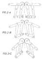
Auf dieser Seite sehen wir das Prinzip der Biegemaschine in drei Positionen.On this page we see the principle of the bending machine in three positions.
In Abbildung 2-A sehen wir, dass die Maschine aus zwei symmetrischen Parallelogrammen besteht.In Figure 2-A we see that the machine consists of two symmetrical parallelograms consists.
Das Parallelogramm A, B, C, D hat einen festen Drehpunkt F.The parallelogram A, B, C, D has a fixed pivot F.
Das Parallelogramm A', B', C', D' hat einen festen Drehpunkt F'.The parallelogram A ', B', C ', D' has a fixed pivot point F '.
Der Synchronisierungsmechanismus zwischen den zwei Armen A und A' besteht aus den Zahnsegmenten, die ein Bestandteil von Arm A, bzw. A' sind.The synchronization mechanism between the two arms A and A 'consists of the tooth segments, which are a part of arm A, and A '.
Die beiden Zahnsegmente greifen ineinander ein. The two toothed segments engage each other.
Die Klemmen H und H' können sich frei nach rechts und links bewegen, sind jedoch zueinander symmetrisch synchronisiert.The terminals H and H 'can move freely to the right and left, but are synchronized symmetrically to each other.
Die gesamte Maschine ist in Bezug auf Achse S symmetrisch.The entire machine is symmetrical with respect to axis S.
Alle Drehpunkte sind so gelagert, dass eine minimale Reibung entsteht.All pivot points are mounted so that minimal friction occurs.
Die Klemmen H und H' sind fest auf den Armen D bzw. D' montiert.The clamps H and H 'are fixedly mounted on the arms D and D' respectively.
Die auf Arm C und C' ausgeübte Winkelverschiebung verursacht über die Arme A und B bzw. A' und B' eine gleiche Winkelverschiebung auf den Klemmen H und H', was in Abbildung 2-B zu sehen ist.The angular displacement exerted on arm C and C 'causes over arms A and B and A 'and B' equal angular displacement on the terminals H and H ', which in Figure 2-B can be seen.
Falls die Arme C und C' bewegt werden, ist das Ergebnis, dass ein reines Biegemoment auf das zwischen den Klemmen H und H' eingespannte Produkt ausgeübt wird (siehe auch Abbildung 1-C).If the arms C and C 'are moved, the result is that a pure bending moment is applied to the clamped between the terminals H and H 'product (see also Figure 1-C).
Durch Ausübung dieses reinen Biegemoments wird das Produkt einen sauberen Radius annehmen.By applying this pure bending moment, the product becomes a clean radius accept.
In Abbildung 2-C ist zu sehen, dass ein integriertes Zahnsegment an den Hebeln C und C' dafür sorgt, dass die Bewegungen dieser Hebel synchronisiert sind.In Figure 2-C it can be seen that an integrated sector gear on the levers C and C 'ensures that the movements of these levers are synchronized.
Dieses Zahnsegment wurde in Abbildung 2-A weggelassen, da sonst die Zahnsegmente von Hebel A und A' nicht sichtbar wären.This sector has been omitted in Figure 2-A, otherwise the tooth segments would not be visible from levers A and A '.
Falls man ein langes Produkt biegen möchte, z. B. ein langes Hydraulikrohr, ist es wichtig, dass ein Teil des Produktes statisch ist.If you want to bend a long product, z. As a long hydraulic pipe, it is important that part of the product is static.
Eine grundsätzliche Lösung hierfür wird in Abbildung 3 beschrieben.A basic solution for this is described in Figure 3.
Auf dieser Seite wird der Biegeprozess in 4 Schritten abgebildet.This page shows the bending process in 4 steps.
Abbildung 3-A zeigt das System mit dem für die Verformung eingespannten Material.Figure 3-A shows the system with the material clamped for deformation.
Abbildung 3-B zeigt das System mit dem eingespannten Material und eine Verformung von 30 Grad.Figure 3-B shows the system with the clamped material and a deformation of 30 degrees.
Abbildung 3-C zeigt das System mit eingespanntem Material und einer Verformung von 60 Grad. Figure 3-C shows the system with clamped material and deformation of 60 degrees.
Abbildung 3-D zeigt das System mit eingespanntem Material und eine Verformung von 90 Grad.Figure 3-D shows the system with clamped material and deformation of 90 degrees.
Der Drehpunkt F des Arms J und die Klemme H' sind Festpunkte.The pivot point F of the arm J and the clamp H 'are fixed points.
Der vorstehende Teil des Produkts O, welches in Klemme H' eingespannt ist, ist statisch.The protruding part of the product O, which is clamped in clamp H ', is static.
Der Ausgangspunkt der Biegemaschine besteht aus zwei Parallelogrammen, gekennzeichnet mit G, J, I, K und gekennzeichnet mit N, M, K, L.The starting point of the bending machine consists of two parallelograms marked with G, J, I, K and denoted by N, M, K, L.
Das Element K verbindet die zwei Parallelogramme in einem Winkel von ca. 90 Grad.The element K connects the two parallelograms at an angle of approximately 90 degrees.
Das erste Parallelogramm, gekennzeichnet mit G, J, I, K übertragt das Moment von Arm J auf das Element K und kann sich vollständig frei in Richtung Q-R bewegen.The first parallelogram, marked G, J, I, K, transmits the momentum of Arm J on the element K and can move completely freely in the direction of Q-R.
Das Parallelogramm, gekennzeichnet mit N, M, K, L, überträgt das Moment von Element K auf dem Arm N und kann sich vollständig frei in Richtung S-T bewegen.The parallelogram, marked N, M, K, L, transmits the moment of element K in the arm N and can move completely freely in the direction of S-T.
Auf dem Arm N ist die Klemme H fest montiert.On the arm N, the clamp H is firmly mounted.
Die Bewegungsrichtung (Q-R und U-T) der zwei Parallelogramme untereinander bleibt ca. 90 Grad.The direction of movement (Q-R and U-T) of the two parallelograms remains with each other about 90 degrees.
Das Moment wird dadurch von Arm J auf Klemme H übertragen, welche sozusagen frei ist, sich in der horizontalen Fläche zu bewegen.The moment is thereby transferred from arm J to terminal H, which releases, so to speak is to move in the horizontal plane.
Hierdurch erfährt Klemme H ausschließlich ein reines Biegemoment, ausgehend von einer zu vernachlässigenden Reibung in allen Drehpunkten.As a result, terminal H experiences only a pure bending moment, starting from a negligible friction in all pivot points.
Wenn auf das Produkt zwischen den beiden Klemmen (H und H') ein reines Biegemoment ausgeübt wird, wird sich das Produkt gleichmäßig verformen (biegen) mit einem gleichmäßigen Radius.If on the product between the two terminals (H and H ') a pure bending moment is exercised, the product will deform evenly (bend) with one uniform radius.
Die Voraussetzung bei diesem Biegeprozess ist, dass das zu biegende Produkt über die zu biegende Länge einen konstanten Querschnitt hat.The prerequisite in this bending process is that the product to be bent over the length to be bent has a constant cross-section.
Der Winkel P, den Arm J um Punkt F macht, entspricht dem Winkel, den die Klemme H
macht.
Der Radius, den das Produkt erhält, hängt von dem Abstand zwischen den zwei
Klemmen H und H' in der Ausgangsposition sowie dem Winkel ab, den Klemme H
macht.
Da sowohl der Winkel va als auch der Abstand zwischen den zwei Klemmen (H und H')
stufenlos veränderlich ist, ist jeder Radius und jeder Biegewinkel möglich. The angle P made by the arm J about point F corresponds to the angle made by the clamp H.
The radius the product receives depends on the distance between the two clamps H and H 'in the home position and the angle made by clamp H.
Since both the angle va and the distance between the two terminals (H and H ') is infinitely variable, any radius and any bending angle is possible.
Da ein Parallelogramm, bestehend aus zwei Armen, eine praktische Winkelbegrenzung von ca. 100 Grad hat, wird in der Praxis eine drei- (oder mehr) -armige Konstruktion verwendet (z. B. ein "Schmidt Offset Coupling"), um zu einem größeren Biegewinkel zu gelangen. Das Funktionsprinzip bleibt bei Verwendung einer solchen Alternative identisch.Since a parallelogram, consisting of two arms, a practical angle limitation of about 100 degrees, in practice becomes a three (or more) -arm construction used (eg, a "Schmidt Offset Coupling") to provide a larger bend angle reach. The operating principle remains the same when using such an alternative.
Die Aufgabe der Konstruktion mit mehreren Parallelogrammen ist die, ein reines Biegemoment von der festen Klemme H' auf die bewegliche Klemme H zu übertragen.The task of the construction with several parallelograms is the one, a pure bending moment from the fixed terminal H 'to the movable terminal H.
Claims (8)
Applications Claiming Priority (2)
| Application Number | Priority Date | Filing Date | Title |
|---|---|---|---|
| NL1025692 | 2004-03-11 | ||
| NL1025692A NL1025692C1 (en) | 2004-03-11 | 2004-03-11 | Bending machine for bending strips, plates, profiles, around material and thick-walled pipe. |
Publications (2)
| Publication Number | Publication Date |
|---|---|
| EP1574267A1 true EP1574267A1 (en) | 2005-09-14 |
| EP1574267B1 EP1574267B1 (en) | 2007-12-26 |
Family
ID=34825253
Family Applications (1)
| Application Number | Title | Priority Date | Filing Date |
|---|---|---|---|
| EP05005388A Not-in-force EP1574267B1 (en) | 2004-03-11 | 2005-03-11 | Bending press |
Country Status (4)
| Country | Link |
|---|---|
| EP (1) | EP1574267B1 (en) |
| AT (1) | ATE381971T1 (en) |
| DE (1) | DE502005002325D1 (en) |
| NL (1) | NL1025692C1 (en) |
Cited By (1)
| Publication number | Priority date | Publication date | Assignee | Title |
|---|---|---|---|---|
| CN108453159A (en) * | 2018-04-11 | 2018-08-28 | 盐城中自科技有限公司 | A kind of heat exchanger bending mechanism and bending method |
Citations (3)
| Publication number | Priority date | Publication date | Assignee | Title |
|---|---|---|---|---|
| US3952572A (en) * | 1974-01-23 | 1976-04-27 | Case Western Reserve University | Beam bender |
| US4798073A (en) * | 1985-12-13 | 1989-01-17 | Helmut Dischler | Bending machine for bending bars, channels, sections and the like |
| JPH07232217A (en) * | 1994-02-23 | 1995-09-05 | Taitaro Yamamoto | Sheet metal machine |
-
2004
- 2004-03-11 NL NL1025692A patent/NL1025692C1/en not_active IP Right Cessation
-
2005
- 2005-03-11 AT AT05005388T patent/ATE381971T1/en not_active IP Right Cessation
- 2005-03-11 DE DE502005002325T patent/DE502005002325D1/en not_active Expired - Fee Related
- 2005-03-11 EP EP05005388A patent/EP1574267B1/en not_active Not-in-force
Patent Citations (3)
| Publication number | Priority date | Publication date | Assignee | Title |
|---|---|---|---|---|
| US3952572A (en) * | 1974-01-23 | 1976-04-27 | Case Western Reserve University | Beam bender |
| US4798073A (en) * | 1985-12-13 | 1989-01-17 | Helmut Dischler | Bending machine for bending bars, channels, sections and the like |
| JPH07232217A (en) * | 1994-02-23 | 1995-09-05 | Taitaro Yamamoto | Sheet metal machine |
Non-Patent Citations (1)
| Title |
|---|
| PATENT ABSTRACTS OF JAPAN vol. 1996, no. 01 31 January 1996 (1996-01-31) * |
Cited By (1)
| Publication number | Priority date | Publication date | Assignee | Title |
|---|---|---|---|---|
| CN108453159A (en) * | 2018-04-11 | 2018-08-28 | 盐城中自科技有限公司 | A kind of heat exchanger bending mechanism and bending method |
Also Published As
| Publication number | Publication date |
|---|---|
| EP1574267B1 (en) | 2007-12-26 |
| NL1025692C1 (en) | 2005-09-13 |
| ATE381971T1 (en) | 2008-01-15 |
| DE502005002325D1 (en) | 2008-02-07 |
Similar Documents
| Publication | Publication Date | Title |
|---|---|---|
| DE854100C (en) | Flexible bracket | |
| DE4314975C1 (en) | Suspended seat frame, especially for a vehicle seat | |
| DE2824902C2 (en) | Device for the temporary fixing of facade elements | |
| DE1527380B2 (en) | Device for the production of bent pipe pieces | |
| EP1574267A1 (en) | Bending press | |
| DE2112743A1 (en) | Method and device for stretching a long workpiece | |
| DE3840556A1 (en) | CAM STRUCTURE | |
| DE202014002943U1 (en) | Tool for producing a bent part and such a bent part | |
| DE2240895A1 (en) | DEVICE FOR GUIDING CABLES ON BICYCLES | |
| DE852408C (en) | Electric switch | |
| DE10110217A1 (en) | Continuous bending device has at least one bender able to travel along longitudinal track and perpendicularly to it | |
| DE1237408B (en) | Device for bending pipes, rods, profiles or the like. | |
| DE517703C (en) | Device for learning swimming movements | |
| DE3708623A1 (en) | CLUTCH PIECE | |
| AT52640B (en) | Sleeve shapers and straighteners. | |
| AT519740B1 (en) | Device for the production of meanders | |
| DE541112C (en) | Jaw control for board drop hammers moved by eccentric | |
| DE905877C (en) | Yarn guide rail drive device for flat weft knitting machines | |
| DE2244733A1 (en) | METHOD AND DEVICE FOR BENDING A METAL PART | |
| DE19853294A1 (en) | Device for the stretch bending of metal bars or profiles | |
| DE20115469U1 (en) | Hubvervielfachvorrichtung | |
| DE421007C (en) | Device for bending pipe elbows with a straight middle part | |
| DE382941C (en) | Device to prevent twitching and swinging in hoses | |
| DE10163682B4 (en) | Method and device for producing a longitudinally slotted tube made of metal, in particular steel | |
| DE1452914A1 (en) | Method and device for bending material |
Legal Events
| Date | Code | Title | Description |
|---|---|---|---|
| PUAI | Public reference made under article 153(3) epc to a published international application that has entered the european phase |
Free format text: ORIGINAL CODE: 0009012 |
|
| AK | Designated contracting states |
Kind code of ref document: A1 Designated state(s): AT BE BG CH CY CZ DE DK EE ES FI FR GB GR HU IE IS IT LI LT LU MC NL PL PT RO SE SI SK TR |
|
| AX | Request for extension of the european patent |
Extension state: AL BA HR LV MK YU |
|
| 17P | Request for examination filed |
Effective date: 20060222 |
|
| AKX | Designation fees paid |
Designated state(s): AT BE BG CH CY CZ DE DK EE ES FI FR GB GR HU IE IS IT LI LT LU MC NL PL PT RO SE SI SK TR |
|
| 17Q | First examination report despatched |
Effective date: 20070111 |
|
| GRAP | Despatch of communication of intention to grant a patent |
Free format text: ORIGINAL CODE: EPIDOSNIGR1 |
|
| GRAS | Grant fee paid |
Free format text: ORIGINAL CODE: EPIDOSNIGR3 |
|
| GRAA | (expected) grant |
Free format text: ORIGINAL CODE: 0009210 |
|
| AK | Designated contracting states |
Kind code of ref document: B1 Designated state(s): AT BE BG CH CY CZ DE DK EE ES FI FR GB GR HU IE IS IT LI LT LU MC NL PL PT RO SE SI SK TR |
|
| REG | Reference to a national code |
Ref country code: GB Ref legal event code: FG4D Free format text: NOT ENGLISH |
|
| REG | Reference to a national code |
Ref country code: IE Ref legal event code: FG4D Free format text: LANGUAGE OF EP DOCUMENT: GERMAN |
|
| REG | Reference to a national code |
Ref country code: CH Ref legal event code: EP |
|
| REF | Corresponds to: |
Ref document number: 502005002325 Country of ref document: DE Date of ref document: 20080207 Kind code of ref document: P |
|
| PG25 | Lapsed in a contracting state [announced via postgrant information from national office to epo] |
Ref country code: SE Free format text: LAPSE BECAUSE OF FAILURE TO SUBMIT A TRANSLATION OF THE DESCRIPTION OR TO PAY THE FEE WITHIN THE PRESCRIBED TIME-LIMIT Effective date: 20080326 |
|
| PG25 | Lapsed in a contracting state [announced via postgrant information from national office to epo] |
Ref country code: SI Free format text: LAPSE BECAUSE OF FAILURE TO SUBMIT A TRANSLATION OF THE DESCRIPTION OR TO PAY THE FEE WITHIN THE PRESCRIBED TIME-LIMIT Effective date: 20071226 Ref country code: NL Free format text: LAPSE BECAUSE OF FAILURE TO SUBMIT A TRANSLATION OF THE DESCRIPTION OR TO PAY THE FEE WITHIN THE PRESCRIBED TIME-LIMIT Effective date: 20071226 Ref country code: PL Free format text: LAPSE BECAUSE OF FAILURE TO SUBMIT A TRANSLATION OF THE DESCRIPTION OR TO PAY THE FEE WITHIN THE PRESCRIBED TIME-LIMIT Effective date: 20071226 Ref country code: FI Free format text: LAPSE BECAUSE OF FAILURE TO SUBMIT A TRANSLATION OF THE DESCRIPTION OR TO PAY THE FEE WITHIN THE PRESCRIBED TIME-LIMIT Effective date: 20071226 |
|
| NLV1 | Nl: lapsed or annulled due to failure to fulfill the requirements of art. 29p and 29m of the patents act | ||
| GBV | Gb: ep patent (uk) treated as always having been void in accordance with gb section 77(7)/1977 [no translation filed] | ||
| PG25 | Lapsed in a contracting state [announced via postgrant information from national office to epo] |
Ref country code: IS Free format text: LAPSE BECAUSE OF FAILURE TO SUBMIT A TRANSLATION OF THE DESCRIPTION OR TO PAY THE FEE WITHIN THE PRESCRIBED TIME-LIMIT Effective date: 20080426 Ref country code: CZ Free format text: LAPSE BECAUSE OF FAILURE TO SUBMIT A TRANSLATION OF THE DESCRIPTION OR TO PAY THE FEE WITHIN THE PRESCRIBED TIME-LIMIT Effective date: 20071226 Ref country code: ES Free format text: LAPSE BECAUSE OF FAILURE TO SUBMIT A TRANSLATION OF THE DESCRIPTION OR TO PAY THE FEE WITHIN THE PRESCRIBED TIME-LIMIT Effective date: 20080406 Ref country code: LT Free format text: LAPSE BECAUSE OF FAILURE TO SUBMIT A TRANSLATION OF THE DESCRIPTION OR TO PAY THE FEE WITHIN THE PRESCRIBED TIME-LIMIT Effective date: 20071226 |
|
| PGFP | Annual fee paid to national office [announced via postgrant information from national office to epo] |
Ref country code: DE Payment date: 20080304 Year of fee payment: 4 |
|
| PG25 | Lapsed in a contracting state [announced via postgrant information from national office to epo] |
Ref country code: SK Free format text: LAPSE BECAUSE OF FAILURE TO SUBMIT A TRANSLATION OF THE DESCRIPTION OR TO PAY THE FEE WITHIN THE PRESCRIBED TIME-LIMIT Effective date: 20071226 Ref country code: RO Free format text: LAPSE BECAUSE OF FAILURE TO SUBMIT A TRANSLATION OF THE DESCRIPTION OR TO PAY THE FEE WITHIN THE PRESCRIBED TIME-LIMIT Effective date: 20071226 |
|
| BERE | Be: lapsed |
Owner name: DAKO WERK DOWIDAT K.G. Effective date: 20080331 |
|
| PG25 | Lapsed in a contracting state [announced via postgrant information from national office to epo] |
Ref country code: PT Free format text: LAPSE BECAUSE OF FAILURE TO SUBMIT A TRANSLATION OF THE DESCRIPTION OR TO PAY THE FEE WITHIN THE PRESCRIBED TIME-LIMIT Effective date: 20080526 |
|
| REG | Reference to a national code |
Ref country code: IE Ref legal event code: FD4D |
|
| EN | Fr: translation not filed | ||
| PG25 | Lapsed in a contracting state [announced via postgrant information from national office to epo] |
Ref country code: MC Free format text: LAPSE BECAUSE OF NON-PAYMENT OF DUE FEES Effective date: 20080331 Ref country code: DK Free format text: LAPSE BECAUSE OF FAILURE TO SUBMIT A TRANSLATION OF THE DESCRIPTION OR TO PAY THE FEE WITHIN THE PRESCRIBED TIME-LIMIT Effective date: 20071226 Ref country code: IE Free format text: LAPSE BECAUSE OF FAILURE TO SUBMIT A TRANSLATION OF THE DESCRIPTION OR TO PAY THE FEE WITHIN THE PRESCRIBED TIME-LIMIT Effective date: 20071226 |
|
| PLBE | No opposition filed within time limit |
Free format text: ORIGINAL CODE: 0009261 |
|
| STAA | Information on the status of an ep patent application or granted ep patent |
Free format text: STATUS: NO OPPOSITION FILED WITHIN TIME LIMIT |
|
| 26N | No opposition filed |
Effective date: 20080929 |
|
| PG25 | Lapsed in a contracting state [announced via postgrant information from national office to epo] |
Ref country code: GB Free format text: LAPSE BECAUSE OF FAILURE TO SUBMIT A TRANSLATION OF THE DESCRIPTION OR TO PAY THE FEE WITHIN THE PRESCRIBED TIME-LIMIT Effective date: 20071226 |
|
| PG25 | Lapsed in a contracting state [announced via postgrant information from national office to epo] |
Ref country code: EE Free format text: LAPSE BECAUSE OF FAILURE TO SUBMIT A TRANSLATION OF THE DESCRIPTION OR TO PAY THE FEE WITHIN THE PRESCRIBED TIME-LIMIT Effective date: 20071226 Ref country code: GR Free format text: LAPSE BECAUSE OF FAILURE TO SUBMIT A TRANSLATION OF THE DESCRIPTION OR TO PAY THE FEE WITHIN THE PRESCRIBED TIME-LIMIT Effective date: 20080327 |
|
| PG25 | Lapsed in a contracting state [announced via postgrant information from national office to epo] |
Ref country code: BE Free format text: LAPSE BECAUSE OF NON-PAYMENT OF DUE FEES Effective date: 20080331 |
|
| PG25 | Lapsed in a contracting state [announced via postgrant information from national office to epo] |
Ref country code: FR Free format text: LAPSE BECAUSE OF FAILURE TO SUBMIT A TRANSLATION OF THE DESCRIPTION OR TO PAY THE FEE WITHIN THE PRESCRIBED TIME-LIMIT Effective date: 20081017 Ref country code: BG Free format text: LAPSE BECAUSE OF FAILURE TO SUBMIT A TRANSLATION OF THE DESCRIPTION OR TO PAY THE FEE WITHIN THE PRESCRIBED TIME-LIMIT Effective date: 20080326 |
|
| PG25 | Lapsed in a contracting state [announced via postgrant information from national office to epo] |
Ref country code: CY Free format text: LAPSE BECAUSE OF FAILURE TO SUBMIT A TRANSLATION OF THE DESCRIPTION OR TO PAY THE FEE WITHIN THE PRESCRIBED TIME-LIMIT Effective date: 20071226 |
|
| PG25 | Lapsed in a contracting state [announced via postgrant information from national office to epo] |
Ref country code: AT Free format text: LAPSE BECAUSE OF NON-PAYMENT OF DUE FEES Effective date: 20080311 |
|
| REG | Reference to a national code |
Ref country code: CH Ref legal event code: PL |
|
| PG25 | Lapsed in a contracting state [announced via postgrant information from national office to epo] |
Ref country code: CH Free format text: LAPSE BECAUSE OF NON-PAYMENT OF DUE FEES Effective date: 20090331 Ref country code: LI Free format text: LAPSE BECAUSE OF NON-PAYMENT OF DUE FEES Effective date: 20090331 Ref country code: DE Free format text: LAPSE BECAUSE OF NON-PAYMENT OF DUE FEES Effective date: 20091001 |
|
| PG25 | Lapsed in a contracting state [announced via postgrant information from national office to epo] |
Ref country code: LU Free format text: LAPSE BECAUSE OF NON-PAYMENT OF DUE FEES Effective date: 20080311 Ref country code: HU Free format text: LAPSE BECAUSE OF FAILURE TO SUBMIT A TRANSLATION OF THE DESCRIPTION OR TO PAY THE FEE WITHIN THE PRESCRIBED TIME-LIMIT Effective date: 20080627 |
|
| PG25 | Lapsed in a contracting state [announced via postgrant information from national office to epo] |
Ref country code: TR Free format text: LAPSE BECAUSE OF FAILURE TO SUBMIT A TRANSLATION OF THE DESCRIPTION OR TO PAY THE FEE WITHIN THE PRESCRIBED TIME-LIMIT Effective date: 20071226 |
|
| PG25 | Lapsed in a contracting state [announced via postgrant information from national office to epo] |
Ref country code: IT Free format text: LAPSE BECAUSE OF NON-PAYMENT OF DUE FEES Effective date: 20080331 |