EP1566151B1 - Dentalmedizinische Zange mit trennbaren Hälften - Google Patents
Dentalmedizinische Zange mit trennbaren Hälften Download PDFInfo
- Publication number
- EP1566151B1 EP1566151B1 EP05001310A EP05001310A EP1566151B1 EP 1566151 B1 EP1566151 B1 EP 1566151B1 EP 05001310 A EP05001310 A EP 05001310A EP 05001310 A EP05001310 A EP 05001310A EP 1566151 B1 EP1566151 B1 EP 1566151B1
- Authority
- EP
- European Patent Office
- Prior art keywords
- forceps
- bore
- pliers
- pin
- joint
- Prior art date
- Legal status (The legal status is an assumption and is not a legal conclusion. Google has not performed a legal analysis and makes no representation as to the accuracy of the status listed.)
- Active
Links
Images


Classifications
-
- A—HUMAN NECESSITIES
- A61—MEDICAL OR VETERINARY SCIENCE; HYGIENE
- A61B—DIAGNOSIS; SURGERY; IDENTIFICATION
- A61B17/00—Surgical instruments, devices or methods, e.g. tourniquets
- A61B17/28—Surgical forceps
- A61B17/2812—Surgical forceps with a single pivotal connection
- A61B17/2816—Pivots
-
- A—HUMAN NECESSITIES
- A61—MEDICAL OR VETERINARY SCIENCE; HYGIENE
- A61C—DENTISTRY; APPARATUS OR METHODS FOR ORAL OR DENTAL HYGIENE
- A61C3/00—Dental tools or instruments
- A61C3/14—Dentists' forceps or the like for extracting teeth
-
- A—HUMAN NECESSITIES
- A61—MEDICAL OR VETERINARY SCIENCE; HYGIENE
- A61B—DIAGNOSIS; SURGERY; IDENTIFICATION
- A61B90/00—Instruments, implements or accessories specially adapted for surgery or diagnosis and not covered by any of the groups A61B1/00 - A61B50/00, e.g. for luxation treatment or for protecting wound edges
- A61B90/08—Accessories or related features not otherwise provided for
- A61B2090/0813—Accessories designed for easy sterilising, i.e. re-usable
Definitions
- the invention relates to a dental forceps, in particular an extraction forceps.
- Extraction forceps consist of two forceps parts, each having a jaw and a grip leg.
- the pliers are called by a joint, also called castle or trade, pivotally connected to each other.
- the jaws of the pliers parts form the pliers mouth, while the grip legs form the pliers handle.
- the joint is as an applied joint, in which the two pliers parts are placed and connected to each other, as an inserted joint in which one pliers part is inserted into a cutout of the other pliers part and connected to this, or designed as a plug-through joint, in which one pliers part is pushed through a recess of the other pliers part.
- the two pliers parts are riveted together in the pivot axis, so that the two pliers parts are inextricably linked. It is also known to connect the two pliers parts by a arranged in the pivot axis screw together. Here, a separation of the pliers parts is possible, which is particularly advantageous for cleaning, disinfection and optionally sterilization. However, disassembling the forceps is cumbersome and time consuming.
- the document DE 743 853 C discloses a surgical instrument having a releasable hinge formed from a peripheral lobed pin and a corresponding bore.
- the invention has for its object to provide a dental forceps, which can be easily disassembled and reassembled.
- the joint is formed by a pin formed on one pliers part and a corresponding hole formed in the other pliers part.
- the pin is inserted into the bore and forms the pivot joint, wherein the circular cylindrical pin is guided in the formed with the same diameter circular cylindrical bore.
- the bore has in its wall a circumferential groove and accordingly, the pin has on its outer peripheral surface at least one circumferential tab.
- the peripheral tab of the pin engages in the circumferential groove of the bore, whereby the pin is axially positively held in the bore and whereby the two pliers parts are pivotally connected together.
- the at least one circumferential tab is formed only over a partial angle range of the circumference.
- the pin can be inserted into or pulled out of the bore.
- This angular position corresponds to the spread position of the pliers with maximum opening of the pliers mouth. If the pin is inserted into the hole, the pliers will be in their closing or gripping position pivoted. In this case, the circumferential tab is pivoted in its angular position against the circumferential groove, so that the circumferential tab engages in the circumferential groove and the pin is thereby held axially positive fit in the bore.
- the forceps parts are pivoted in accordance with the required opening of the forceps jaw only in a Sp Dahl Anlagenwitz Anlagenwitz
- the two pliers are therefore always reliably connected to each other for the use of the pliers. If the pliers are to be disassembled for cleaning, the pliers parts have to be spread apart only beyond the normal use pivot position until the at least one circumferential tab comes into the angular range of the at least one inlet channel, so that the pin can now be pulled out of the hole axially and the two pliers parts can be separated from each other.
- the bore is formed as closed at its base blind hole.
- a Bremseinlage between the mutually contacting surfaces of the pin and the bore may be provided.
- This brake insert has the function of causing a defined resistance in the pivoting movement of the pliers. By choosing the material and the dimensioning of the brake insert a defined predetermined resistance can be generated, so that the forceps can be operated on the one hand sufficiently smooth and on the other hand does not move unintentionally from the respective pivot position. If the bore is formed as a blind bore, then the brake insert can be useful as a disc between the bottom of the bore and the axial end face of the pin can be used. This ensures a uniform braking effect in each rotational position and a uniform wear of the brake insert.
- the invention also relates to a low-cost production of the dental forceps described above.
- the pliers parts of the pliers described above are made of two pieces.
- the parts of the forceps that require high precision, namely the forceps jaw and the joint, are milled or turned and drilled or die-cast while the grip legs are attached to the respective jaw and hinge forming part of the handle.
- These grip legs require less stringent material and machining precision. This results in a total savings in material and manufacturing costs.
- the forceps which is shown in the embodiment as a tooth extraction forceps, consists of two pliers parts 10 and 12.
- the two pliers parts 10 and 12 consist in a conventional manner each of a jaw 14 and 16, a gripping arms 18 and 20 and a joint area 22 and 24, which connects the respective jaw 14 and 16 with the respective gripping arms 18 and 20 respectively.
- the jaws 14 and 16 form the forceps jaw and are designed according to the particular application of the forceps.
- the gripping arms 18 and 20 form the gripper handle and are also adapted according to the particular intended use of the pliers.
- the two pliers parts 10 and 12 are pivotally connected to each other by a hinge, which is subsequently based on the FIGS. 2 to 7 will be explained in detail.
- the joint is inserted as Joint formed in which the joint portions 22 and 24 each have milled recesses into which the corresponding hinge portion 22 and 24 of the other pliers part 10 and 12 is inserted. It is obvious that the joint can also be designed as an applied joint.
- FIGS. 2 and 3 the hinge portion 24 of the second pliers member 12 is shown.
- pin 26 is formed at the joint area 24 a directed against the hinge portion 22 of the first pliers member 10 .
- the pin 26 has the shape of a straight circular cylinder whose central axis coincides with the pivot axis of the pliers.
- a peripheral collar 28 is integrally formed on the outer circumference thereof.
- the peripheral collar is milled on two diametrically opposite sides, so that parallel to the longitudinal extent of the pliers part 12 extending flat sides 30 result. The milling is performed up to the diameter of the pin 26, so that the flat sides 30 have a diameter of the pin 26 corresponding distance.
- the circumferential collar thereby forms two diametrically arranged circumferential tabs 28 which protrude in the direction of the longitudinal extent of the pliers part 12 in the distal or proximal direction.
- the axial height of the pin 26 is slightly less than the milled portion 22 of the first pliers member 10 receiving milled portion of the hinge portion 24, as in FIG. 2 is indicated by a dashed line.
- This hinge portion 22 has a bore 32 whose diameter corresponds to the diameter of the pin 26 and whose central axis coincides with the pivot axis of the pliers.
- the bore 32 is formed as a blind bore, whose axial depth is slightly larger than the axial height of the pin 26. In half the depth of the bore 32 is in the inner circumference a circumferential groove 34 incorporated.
- the circumferential groove 34 corresponds in its axial position, in its axial width and in its radial depth in each case the axial position, the axial width and the radial height of the peripheral tabs 28 of the pin 26.
- the Diameter of the bore 32 extends on two diametrical sides into the circumferential groove 34 into the outer diameter of the circumferential groove 34.
- two entrance grooves 36 are formed, which lead from the surface of the hinge portion 22 into the circumferential groove 34 and correspond in cross-sectional shape and the cross-sectional dimensions of the circumferential tabs 28 of the second pliers member 12.
- the entrance grooves 36 are aligned so that they are perpendicular to the longitudinal extent of the pliers part 10.
- the two pliers parts 10 and 12 are arranged with their longitudinal axes perpendicular to each other.
- the circumferential tabs 28 come in their angular position with the inlet channels 36 to cover.
- the pin 26 can now be inserted axially into the bore 32, wherein the circumferential tabs 28 passes through the kitrinnen 36 in the axial region of the circumferential groove 34.
- the pliers parts 10 and 12 are pivoted in the closing direction against each other.
- the circumferential tabs 28 are rotated relative to the inlet grooves 36 and enter the circumferential groove 34.
- the pliers are ready for use.
- the pin 26 is rotatably guided in the bore 32 and is held by the engaging in the circumferential groove 34 circumferential tabs 28 in the axial direction positively in the bore 32.
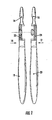
- the bore 32 can also be formed as a through hole, as shown in FIG. 1 is shown.
- the formation of the bore 23 as a blind hole has the advantage that the joint is visible neither from the outside of the hinge portion 22 nor from the outside of the hinge portion 24.
- a brake insert 38 is inserted into the joint.
- the brake pad 38 may be made of a suitable material such as a plastic having a defined elasticity and lubricity in mating with the metal of the hinge portions 22 and 24, respectively.
- the brake insert 38 can be used for example in one of the axial end faces of the circumferential groove 34 so that it occurs in braking action with the peripheral tabs 28 of the pin. Is the bore 32 formed as a blind bore, as in the FIGS.
- the brake pad 38 is preferably arranged as a circular disc at the bottom of the bore 32 so that it occurs in braking action with the axial end face of the pin 26; like this in FIG. 6 is indicated.
- circumferential tab 28 instead of two diametrical circumferential tabs 28, only one radially projecting circumferential tabs can be provided, whereby correspondingly only one inlet channel 36 is provided.
- the arrangement of the circumferential tab 28 and the entrance trough 36 is aligned so that the cross-sectional area of the circumferential tabs 28 with the cross-sectional area of the entrance trough 36 then to cover comes when the pliers parts 10 and 12 are aligned according to a maximum opening spread of the pliers.
- any other pivotal position of the circumferential tabs 28 engages in the circumferential groove 34, so that the pin 26 is axially positively held in the bore 32 and thus the pliers parts 10 and 12 are pivotally connected to each other.
- the jaw 14 with the hinge portion 22 and the jaw 16 with the hinge portion 24 are each made as a one-piece part of a suitable metal, in particular a suitable steel. These parts are made especially by milling, turning and drilling. The material used and the manufacturing processes ensure optimum precision and strength in the parts which are essential for the use of the forceps, namely the forceps jaw and the joint.
- the grip legs 18 and 20 are made as separate workpieces.
- the grip legs 18 and 20 are fixedly connected to the respective hinge portions 22 and 24, respectively.
- the grip legs 18 and 20 can be dovetailed, soldered or glued to the joint areas 22 and 24. Since there is no need to set such high demands on precision and material properties on the gripper handle formed by the gripping legs 18 and 20, the selection of the material and the manufacturing method for the gripping legs 18 and 20 can be made from the viewpoint of the most favorable manufacturing cost.
- FIG. 8 shows the pliers in the in FIG. 1 illustrated embodiment.
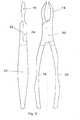
- FIG. 9 shows a pair of pliers with the same forceps jaw as the pliers of the FIG. 8 However, the grip legs 18 and 20 are formed differently.
- FIG. 10 shows a pair of pliers, with a bent jaw mouth, which is combined with gripping arms 18 and 20, the handle legs 18 and 20 of the embodiment of the FIG. 9 correspond.
- FIG. 11 shows a pair of pliers with an angled forceps jaw and another angled version of the gripping arms 18 and 20.
Description
- Die Erfindung betrifft eine dentalmedizinische Zange, insbesondere eine Extraktionszange .
- Zangen allgemein und insbesondere dentalmedizinische Zangen, z. B. Extraktionszangen bestehen aus zwei Zangenteilen, die jeweils eine Backe und einen Griffschenkel aufweisen. Die Zangenteile sind durch ein Gelenk, auch Schloss oder Gewerbe genannt, schwenkbar miteinander verbunden. Die Backen der Zangenteile bilden das Zangenmaul, während die Griffschenkel den Zangengriff bilden. Bei den bekannten Zangen ist das Gelenk als aufgelegtes Gelenk, bei dem die beiden Zangenteile aufeinander gelegt und verbunden werden, als eingelegtes Gelenk, bei dem das eine Zangenteil in eine Ausfräsung des anderen Zangenteils eingelegt und mit diesem verbunden wird, oder als durchgestecktes Gelenk ausgebildet, bei welchem das eine Zangenteil durch eine Aussparung des anderen Zangenteils hindurchgeschoben wird. Die beiden Zangenteile werden in der Schwenkachse miteinander vernietet, so dass die beiden Zangenteile untrennbar miteinander verbunden sind. Ebenso ist es bekannt, die beiden Zangenteile durch eine in der Schwenkachse angeordnete Schraube miteinander zu verbinden. Hier ist eine Trennung der Zangenteile möglich, was insbesondere für die Reinigung, Desinfektion und gegebenenfalls Sterilisierung vorteilhaft ist. Das Zerlegen der Zange ist dabei jedoch umständlich und zeitraubend.
- Das Dokument
DE 743 853 C offenbart ein chirurgisches Instrument mit einem aus einem mit Umfangslappen versehenen Zapfen und einer entsprechenden Bohrung gebildeten lösbaren Gelenk. Der Erfindung liegt die Aufgabe zugrunde, eine dentalmedizinische Zange zu schaffen, die einfach zerlegt und wieder zusammengesetzt werden kann. - Diese Aufgabe wird erfindungsgemäß gelöst durch eine dentalmedizinische Zange mit den Merkmalen des Anspruchs 1.
- Vorteilhafte Ausführungen der Erfindung sind in den rückbezogenen Unteransprüchen angegeben.
- Bei der erfindungsgemäßen Zange wird das Gelenk durch einen an dem einen Zangenteil ausgebildeten Zapfen und eine in dem anderen Zangenteil ausgebildete entsprechende Bohrung gebildet. Der Zapfen wird in die Bohrung eingesteckt und bildet das Schwenkgelenk, bei welchem der kreiszylindrische Zapfen in der mit demselben Durchmesser ausgebildeten kreiszylindrischen Bohrung geführt wird. Die Bohrung weist in ihrer Wandung eine Umfangsnut auf und entsprechend weist der Zapfen an seiner Außenumfangsfläche wenigstens einen Umfangslappen auf. Der Umfangslappen des Zapfens greift in die Umfangsnut der Bohrung ein, wodurch der Zapfen axial formschlüssig in der Bohrung gehalten wird und wodurch die zwei Zangenteile schwenkbar miteinander verbunden sind. Um die Zange zerlegen und wieder zusammensetzen zu können, ist der wenigstens eine Umfangslappen nur über einen Teilwinkelbereich des Umfangs ausgebildet. Werden die zwei Zangenteile in ihrer gegenseitigen Winkelstellung so ausgerichtet, dass der wenigstens eine Umfangslappen im Winkelbereich mit zu der Umfangsnut führenden Eintrittsrinnen zur Deckung kommt, so kann der Zapfen in die Bohrung eingesteckt oder aus dieser herausgezogen werden. Diese Winkelstellung entspricht der Spreizstellung der Zange mit maximaler Öffnung des Zangenmaules. Ist der Zapfen in die Bohrung eingesteckt, so wird die Zange in ihre Schließ- bzw. Greifstellung verschwenkt. Dabei wird auch der Umfangslappen in seiner Winkelstellung gegen die Umfangsnut verschwenkt, so dass der Umfangslappen in die Umfangsnut eingreift und der Zapfen dadurch axial formschlüssig in der Bohrung gehalten wird. Während des Gebrauchs der Zange werden die Zangenteile entsprechend der erforderlichen Öffnung des Zangenmaules nur in einem Spreizwinkelbereich verschwenkt, in welchem der Umfangslappen nicht aus der Umfangsnut herausgedreht wird. Die beiden Zangenteile sind daher für den Gebrauch der Zange stets zuverlässig miteinander verbunden. Soll die Zange zur Reinigung zerlegt werden, so müssen die Zangenteile nur über die normale Gebrauchsschwenkstellung hinaus auseinander gespreizt werden, bis der wenigstens eine Umfangslappen in den Winkelbereich der wenigstens einen Eintrittsrinne kommt, so dass der Zapfen nun axial aus der Bohrung herausgezogen werden kann und die beiden Zangenteile voneinander getrennt werden können. Sowohl für das Zerlegen als auch für das Zusammensetzen der Zange sind somit keine zusätzlichen Verbindungsmittel erforderlich, die in umständlicher Weise befestigt bzw. gelöst werden müssen. Es genügt sowohl für das Zerlegen als auch für das Zusammensetzen ein einfacher Handgriff, ohne dass zusätzliche Werkzeuge erforderlich sind.
- In einer vorteilhaften Ausführung ist die Bohrung als an ihrem Grund geschlossene Sackbohrung ausgebildet. Dadurch sind weder der Zapfen noch die Bohrung an der jeweiligen Gelenkaußenseite der Zangenteile sichtbar.
- Weiter kann eine Bremseinlage zwischen den miteinander in Berührung stehenden Flächen des Zapfens und der Bohrung vorgesehen sein. Diese Bremseinlage hat die Funktion, einen definierten Widerstand bei der Schwenkbewegung der Zange zu bewirken. Durch die Wahl des Materials und der Dimensionierung der Bremseinlage kann ein definiert vorgegebener Widerstand erzeugt werden, so dass die Zange einerseits ausreichend leichtgängig betätigt werden kann und andererseits sich nicht unbeabsichtigt aus der jeweiligen Schwenkstellung bewegt. Ist die Bohrung als Sackbohrung ausgebildet, so kann die Bremseinlage zweckmäßig als Scheibe zwischen den Grund der Bohrung und die axiale Stirnfläche des Zapfens eingesetzt werden. Dadurch ist eine gleichmäßige Bremswirkung in jeder Drehstellung und ein gleichmäßiger Verschleiß der Bremseinlage gewährleistet.
- Die Erfindung betrifft auch eine kostengünstige Fertigung der oben beschriebenen dentalmedizinischen Zange.
- Bei bekannten dentalmedizinischen Zangen werden zunächst einstückige Rohlinge für die Zangenteile als Press-Schmiedeteile hergestellt, die dann bearbeitet werden. Diese Herstellung ist arbeitsintensiv und daher kostenaufwendig. Erfindungsgemäß werden die Zangenteile der oben beschriebenen Zange dagegen aus zwei Stücken gefertigt. Die Teile der Zange, die eine hohe Präzision erfordern, nämlich das Zangenmaul und das Gelenk werden gefräst bzw. gedreht und gebohrt oder durch Druckguss hergestellt, während die Griffschenkel an das jeweilige die Backe und das Gelenk bildende Stück des Griffteiles angesetzt werden. Für diese Griffschenkel sind weniger hohe Anforderungen in Bezug auf das Material und die Bearbeitungspräzision erforderlich. Dadurch ergibt sich insgesamt eine Ersparnis an Material- und Herstellungskosten. Außerdem ist es möglich, Zangenmäuler und Zangengriffe in unterschiedlicher Weise miteinander zu kombinieren, so dass eine größere Typen-Vielfalt der Zange hergestellt werden kann, ohne dass für jede Type ein eigener Rohling gefertigt werden muss.
- Im folgenden wird die Erfindung anhand von in der Zeichnung dargestellten Ausführungsbeispielen näher erläutert. Es zeigen:
-
Figur 1 eine im Bereich des Gelenks axial geschnittene Seitenansicht der Zange in einer ersten Ausführung im zerlegten Zustand, -
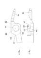
Figur 2 eine Seitenansicht des Gelenkbereichs des zweiten Zangenteils, -
Figur 3 eine Draufsicht auf den Gelenkbereich des zweiten Zangenteils, -
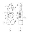
Figur 4 eine Seitenansicht des Gelenkbereichs des ersten Zangenteils, -
Figur 5 eine Draufsicht auf den Gelenkbereich des ersten Zangenteils, -
Figur 6 eine Seitenansicht des Gelenkbereichs der zusammengesetzten Zange, -
Figur 7 eine Draufsicht auf den Gelenkbereich der zusammengesetzten Zange, -
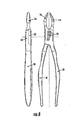
Figur 8 zwei Ansichten der zusammengesetzten Zange in der Ausführung derFigur 1 , -
Figur 9 zwei Ansichten der Zange in einer zweiten Ausführung, -
Figur 10 zwei Ansichten der Zange in einer dritten Ausführung und -
Figur 11 zwei Ansichten der Zange in einer vierten Ausführung. - Die Zange die im Ausführungsbeispiel als Zahn-Extraktionszange dargestellt ist, besteht aus zwei Zangenteilen 10 und 12. Die beiden Zangenteile 10 und 12 bestehen in an sich bekannter Weise aus jeweils einer Backe 14 bzw. 16, einem Griffschenkel 18 bzw. 20 und einem Gelenkbereich 22 bzw. 24, der die jeweilige Backe 14 bzw. 16 mit dem jeweiligen Griffschenkel 18 bzw. 20 verbindet. Die Backen 14 und 16 bilden das Zangenmaul und sind dem jeweiligen Anwendungszweck der Zange entsprechend ausgebildet. Die Griffschenkel 18 und 20 bilden den Zangengriff und sind ebenfalls entsprechend dem jeweiligen Verwendungszweck der Zange angepasst.
- Die beiden Zangenteile 10 und 12 sind durch ein Gelenk schwenkbar miteinander verbunden, welches nachfolgend anhand der
Figuren 2 bis 7 im Einzelnen erläutert wird. Im dargestellten Ausführungsbeispiel ist das Gelenk als eingelegtes Gelenk ausgebildet, bei welchem die Gelenkbereiche 22 und 24 jeweils eingefräste Aussparungen aufweisen, in die der korrespondierende Gelenkbereich 22 bzw. 24 des anderen Zangenteils 10 bzw. 12 eingelegt wird. Es ist offensichtlich, dass das Gelenk auch als aufgelegtes Gelenk ausgebildet sein kann. - In den
Figuren 2 und 3 ist der Gelenkbereich 24 des zweiten Zangenteiles 12 dargestellt. An dem Gelenkbereich 24 ist ein gegen den Gelenkbereich 22 des ersten Zangenteils 10 gerichteter Zapfen 26 angeformt. Der Zapfen 26 hat die Form eines geraden Kreiszylinders, dessen Mittelachse mit der Schwenkachse der Zange zusammenfällt. Etwa auf halber Höhe des Zapfens 26 ist an dessen Außenumfang ein Umfangsbund 28 angeformt. Der Umfangsbund ist an zwei diametral liegenden Seiten abgefräst, so dass sich parallel zur Längserstreckung des Zangenteiles 12 verlaufende Flachseiten 30 ergeben. Die Abfräsung ist bis auf den Durchmesser des Zapfens 26 geführt, so dass die Flachseiten 30 einen Durchmesser des Zapfens 26 entsprechenden Abstand aufweisen. Der Umfangsbund bildet dadurch zwei diametral angeordneten Umfangslappen 28, die in Richtung der Längserstreckung des Zangenteils 12 in distaler bzw. proximaler Richtung abstehen. Die axiale Höhe des Zapfens 26 ist etwas geringer als die den Gelenkbereich 22 des ersten Zangenteils 10 aufnehmende Einfräsung des Gelenkbereichs 24, wie inFigur 2 durch eine strichpunktierte Linie angedeutet ist. - In den
Figuren 4 und 5 ist der Gelenkbereich 22 des ersten Zangenteils 10 dargestellt. Dieser Gelenkbereich 22 weist eine Bohrung 32 auf, deren Durchmesser dem Durchmesser des Zapfens 26 entspricht und deren Mittelachse mit der Schwenkachse der Zange zusammenfällt. Die Bohrung 32 ist als Sackbohrung ausgebildet, deren axiale Tiefe geringfügig größer ist als die axiale Höhe des Zapfens 26. In halber Tiefe der Bohrung 32 ist in deren Innenumfang eine Umfangsnut 34 eingearbeitet. Die Umfangsnut 34 entspricht in ihrer axialen Position, in ihrer axialen Breite und in ihrer radialen Tiefe jeweils der axialen Position, der axialen Breite und der radialen Höhe der Umfangslappen 28 des Zapfens 26. Auf der dem zweiten Zangenteil 12 zugewandten Seite des Gelenkbereiches 22 ist der Durchmesser der Bohrung 32 auf zwei diametralen Seiten bis in die Umfangsnut 34 hinein auf den Aussendurchmesser der Umfangsnut 34 erweitert. Dadurch werden zwei Eintrittsrinnen 36 gebildet, die von der Oberfläche des Gelenkbereichs 22 bis in die Umfangsnut 34 führen und in der Querschnittsform und den Querschnittsabmessungen den Umfangslappen 28 des zweiten Zangenteils 12 entsprechen. Die Eintrittrinnen 36 sind so ausgerichtet, dass sie senkrecht zur Längserstreckung des Zangenteils 10 weisen. Um die beiden Zangenteile 10 und 12 zusammenzusetzen, werden die beiden Zangenteile 10 und 12 mit ihren Längsachsen senkrecht zueinander angeordnet. Dadurch kommen die Umfangslappen 28 in ihrer Winkelstellung mit den Eintrittsrinnen 36 zur Deckung. Der Zapfen 26 kann nun in die Bohrung 32 axial eingeschoben werden, wobei die Umfangslappen 28 durch die Eintrittrinnen 36 in den axialen Bereich der Umfangsnut 34 gelangt. Nun werden die Zangenteile 10 und 12 in Schließrichtung gegeneinander verschwenkt. Dadurch werden die Umfangslappen 28 gegenüber den Eintrittsrinnen 36 verdreht und treten in die Umfangsnut 34 ein. In dieser Stellung ist die Zange für den Einsatz bereit. Dabei ist der Zapfen 26 in der Bohrung 32 drehbar geführt und wird durch die in die Umfangsnut 34 eingreifenden Umfangslappen 28 in axialer Richtung formschlüssig in der Bohrung 32 gehalten. - Es ist offensichtlich, dass die Bohrung 32 auch als durchgehende Bohrung ausgebildet sein kann, wie dies in
Figur 1 dargestellt ist. Die Ausbildung der Bohrung 23 als Sackbohrung hat den Vorteil, dass das Gelenk weder von der Außenseite des Gelenkbereichs 22 noch von der Außenseite des Gelenkbereichs 24 sichtbar ist. - Um die Zange leichtgängig öffnen und schließen zu können und dennoch eine unbeabsichtigte Schwenkbewegung der Zangenteile 10 und 12 gegeneinander zu verhindern, ist vorzugsweise eine Bremseinlage 38 in das Gelenk eingesetzt. Die Bremseinlage 38 kann aus einem geeigneten Material z.B. einem Kunststoff bestehen, welches eine definierte Elastizität und Gleitfähigkeit in der Paarung mit dem Metall der Gelenkbereiche 22 bzw. 24 aufweist. Die Bremseinlage 38 kann beispielsweise in eine der axialen Stirnflächen der Umfangsnut 34 eingesetzt werden, so dass sie in Bremswirkung mit den Umfangslappen 28 des Zapfens tritt. Ist die Bohrung 32 als Sackbohrung ausgebildet, wie dies in den
Figuren 2 bis 7 dargestellt ist, so wird die Bremseinlage 38 vorzugsweise als Kreisscheibe am Grund der Bohrung 32 angeordnet, so dass sie in Bremswirkung mit der axialen Stirnfläche des Zapfens 26 tritt ; wie dies inFigur 6 angedeutet ist. Durch die Wahl des Materials und der Stärke der Bremseinlage 38 kann die Leichtgängigkeit bzw. die Bremswirkung definiert vorgegeben werden. - Anstelle von zwei diametralen Umfangslappen 28 kann auch nur ein radial abstehender Umfangslappen vorgesehen sein, wobei entsprechend auch nur eine Eintrittsrinne 36 vorgesehen ist. Auch hier ist die Anordnung des Umfangslappens 28 und der Eintrittsrinne 36 so ausgerichtet, dass die Querschnittsfläche des Umfangslappen 28 mit der Querschnittsfläche der Eintrittsrinne 36 dann zur Deckung kommt, wenn die Zangenteile 10 und 12 entsprechend einer maximalen Öffnungsspreizung der Zange ausgerichtet sind. In jeder anderen Schwenkstellung greift der Umfangslappen 28 in die Umfangsnut 34 ein, so dass der Zapfen 26 axial formschlüssig in der Bohrung 32 gehalten wird und somit die Zangenteile 10 und 12 schwenkbar miteinander verbunden sind.
- Die Backe 14 mit dem Gelenkbereich 22 und die Backe 16 mit dem Gelenkbereich 24 sind jeweils als einstückiges Teil aus einem geeigneten Metall, insbesondere einem geeigneten Stahl gefertigt. Diese Teile werden insbesondere durch Fräsen, Drehen und Bohren hergestellt. Das verwendete Material und die Herstellungsverfahren gewährleisten eine optimale Präzision und Festigkeit in den für die Verwendung der Zange wesentlichen Teilen, nämlich dem Zangenmaul und dem Gelenk.
- Die Griffschenkel 18 und 20 werden als getrennte Werkstücke hergestellt. Die Griffschenkel 18 und 20 werden mit den jeweiligen Gelenkbereichen 22 bzw. 24 fest verbunden. Hierzu können die Griffschenkel 18 und 20 mit den Gelenkbereichen 22 bzw. 24 verzapft, verlötet oder verklebt werden. Da an den durch die Griffschenkel 18 und 20 gebildeten Zangengriff keine so hohen Anforderungen in Bezug auf die Präzision und die Materialeigenschaften gestellt werden müssen, kann die Auswahl des Materials und des Herstellungsverfahrens für die Griffschenkel 18 und 20 unter dem Gesichtspunkt der günstigsten Herstellungskosten getroffen werden.
- Weiter hat die Herstellung der Backen 14 bzw. 16 und der Gelenkbereiche 22 bzw. 24 einerseits und der Griffschenkel 18 bzw. 20 andererseits als getrennte Werkstücke den Vorteil, dass Zangenmaul und Griffform in unterschiedlicher Weise miteinander kombiniert werden können. Dies ist anhand der
Figuren 8 bis 11 beispielsweise dargestellt.Figur 8 zeigt die Zange in der inFigur 1 dargestellten Ausführung.Figur 9 zeigt eine Zange mit demselben Zangenmaul, wie dies die Zange derFigur 8 aufweist, die Griffschenkel 18 und 20 sind jedoch unterschiedlich ausgebildet.Figur 10 zeigt eine Zange, mit einem abgekröpften Zangenmaul, welches mit Griffschenkeln 18 und 20 kombiniert ist, die den Griffschenkeln 18 und 20 der Ausführung derFigur 9 entsprechen.Figur 11 zeigt eine Zange mit einem abgewinkelten Zangenmaul und einer weiteren abgewinkelten Ausführung der Griffschenkel 18 und 20. -
- 10
- erstes Zangenteil
- 12
- zweites Zangenteil
- 14
- Backe von 10
- 16
- Backe von 12
- 18
- Griffschenkel von 10
- 20
- Griffschenkel von 12
- 22
- Gelenkbereich von 10
- 24
- Gelenkbereich von 12
- 26
- Zapfen
- 28
- Umfangslappen
- 30
- Flachseiten
- 32
- Bohrung
- 34
- Umfangsnut
- 36
- Eintrittsrinnen
- 38
- Bremseinlage
Claims (13)
- Dentalmedizinische Zange mit zwei Zangenteilen, die jeweils eine Backe des Zangenmaules und einen Griffschenkel des Zangengriffes aufweisen und durch ein Gelenk schwenkbar miteinander verbunden sind, wobei das Gelenk einen zur Schwenkachse koaxialen kreiszylindrischen Zapfen (26) des einen Zangenteiles (12) aufweist, der in eine zur Schwenkachse koaxiale kreiszylindrische Bohrung (32) gleichen Durchmessers des anderen Zangenteils (10) eingreift und in dieser Bohrung (32) um die Schwenkachse drehbar ist, wobei der Zapfen (26) und die Bohrung (32) mit wenigstens einem Umfangslappen (28) und einer Umfangsnut (34) in axialer Richtung formschlüssig ineinandergreifen, wobei sich der wenigstens eine Umfangslappen (28) nur über einen Teilwinkelbereich des Umfangs erstreckt und wobei wenigstens eine der Querschnittsform des Umfangslappens (28) entsprechende Eintrittsrinne (36) axial zu der Umfangsnut (34) führt, wobei der wenigstens eine Umfangslappen (28) und die wenigstens eine Eintrittsrinne (36) in dem jeweiligen Gelenkbereich (22 bzw. 24) in ihrer Winkelanordnung so ausgerichtet sind, dass diese in der maximalen Öffnungsspreizstellung der Zangenteile (10, 12) miteinander zur Deckung kommen und der wenigstens eine Umfangslappen (28) durch die wenigstens eine Eintrittsrinne (36) in die Umfangsnut (34) eingeführt bzw. aus dieser herausgehoben werden kann, während in den anderen Spreizstellungen der Zangenteile (10, 12) der wenigstens eine Umfangslappen (28) in die Umfangsnut (34) eingreift und axial formschlüssig in dieser gehalten wird.
- Zange nach Anspruch 1,
dadurch gekennzeichnet, dass das Gelenk als eingelegtes Gelenk ausgebildet ist. - Zange nach Anspruch 1 oder 2,
dadurch gekennzeichnet, dass der wenigstens eine Umfangslappen (28) an dem Zapfen (26) und die Umfangsnut (34) in der Bohrung (32) ausgebildet sind. - Zange nach einem der Ansprüche 1 bis 3,
dadurch gekennzeichnet, dass die Winkelstellungen des wenigstens einen Umfangslappens (28) und der wenigstens einen Eintrittsrinne (36) in den jeweiligen Gelenkbereichen (22) bzw. (24) so ausgerichtet sind, dass diese miteinander zur Deckung kommen, wenn die Zangenteile (10, 12) unter einem maximalen Öffnungsspreizwinkel von etwa 90° angeordnet sind. - Zange nach einem der Ansprüche 1 bis 4,
dadurch gekennzeichnet, dass zwei diametral zueinander angeordneten Umfangslappen (28) und zwei diametral zueinander angeordnete Eintrittsrinnen (36) vorgesehen sind. - Zange nach einem der Ansprüche 1 bis 5,
dadurch gekennzeichnet, dass die Bohrung (32) durchgehend ausgebildet ist. - Zange nach einem der Ansprüche 1 bis 5,
dadurch gekennzeichnet, dass die Bohrung (32) als eine an ihrem Grund geschlossene Sackbohrung ausgebildet ist. - Zange nach einem der Ansprüche 1 bis 7,
dadurch gekennzeichnet, dass zwischen der Wandung der Bohrung (32) und der Wandung des Zapfens (26) eine Bremseinlage (38) angeordnet ist. - Zange nach Anspruch 7 und 8,
dadurch gekennzeichnet, dass die Bremseinlage (38) zwischen dem Grund der Bohrung (32) und der axialen Stirnfläche des Zapfens (26) angeordnet ist. - Zange nach einem der Ansprüche 1 bis 9,
dadurch gekennzeichnet, dass die Zangenteile (10, 12) jeweils aus zwei Stücken gefertigt sind, nämlich aus einem den Griffschenkel (18 bzw. 20) bildenden Stück und einem den Gelenkbereich (22 bzw. 24) und die Backe (14 bzw. 16) bildenden Stück, und dass die zwei Stücke fest miteinander verbunden sind. - Zange nach Anspruch 10,
dadurch gekennzeichnet, dass die zwei Stücke miteinander verzapft, verschweißt oder verklebt sind. - Zange nach Anspruch 10 oder 11,
dadurch gekennzeichnet, dass das den Gelenkbereich (22 bzw. 24) und die Backe (14 bzw. 16) bildenden Stück durch Fräsen, Drehen und Bohren oder Druckguss hergestellt ist. - Zange nach einem der Ansprüche 10 bis 12,
dadurch gekennzeichnet, dass die zwei Stücke aus unterschiedlichen Materialien hergestellt sind.
Priority Applications (1)
| Application Number | Priority Date | Filing Date | Title |
|---|---|---|---|
| PL05001310T PL1566151T3 (pl) | 2004-02-19 | 2005-01-24 | Kleszcze stomatologiczne z rozłącznymi połówkami |
Applications Claiming Priority (2)
| Application Number | Priority Date | Filing Date | Title |
|---|---|---|---|
| DE202004002560U | 2004-02-19 | ||
| DE202004002560U DE202004002560U1 (de) | 2004-02-19 | 2004-02-19 | Dentalmedizinische Zange |
Publications (3)
| Publication Number | Publication Date |
|---|---|
| EP1566151A2 EP1566151A2 (de) | 2005-08-24 |
| EP1566151A3 EP1566151A3 (de) | 2006-04-05 |
| EP1566151B1 true EP1566151B1 (de) | 2011-10-12 |
Family
ID=32186281
Family Applications (1)
| Application Number | Title | Priority Date | Filing Date |
|---|---|---|---|
| EP05001310A Active EP1566151B1 (de) | 2004-02-19 | 2005-01-24 | Dentalmedizinische Zange mit trennbaren Hälften |
Country Status (5)
| Country | Link |
|---|---|
| US (1) | US7318725B2 (de) |
| EP (1) | EP1566151B1 (de) |
| AT (1) | ATE527956T1 (de) |
| DE (1) | DE202004002560U1 (de) |
| PL (1) | PL1566151T3 (de) |
Families Citing this family (20)
| Publication number | Priority date | Publication date | Assignee | Title |
|---|---|---|---|---|
| US9687315B2 (en) | 2002-11-27 | 2017-06-27 | Beak And Bumper, Llc | Dental plier design with offsetting jaw and pad elements for assisting in removing upper and lower teeth utilizing the dental plier design |
| US20110027754A1 (en) * | 2005-03-31 | 2011-02-03 | Richard Golden | Dental pliers with adjustable bumper |
| US9655689B2 (en) * | 2005-03-31 | 2017-05-23 | Beak And Bumper, Llc | Forceps for molar extraction |
| US8152834B2 (en) * | 2005-04-13 | 2012-04-10 | Synthes Usa, Llc | Forceps and system using same |
| WO2007038308A1 (en) * | 2005-09-23 | 2007-04-05 | Bruns Daniel Kidd | Tool to crimp non-metallic tubing onto fittings |
| FR2905257B1 (fr) * | 2006-09-05 | 2009-04-03 | Landanger Sa | Articulation pour instrumentation chirurgicale. |
| SE531737C2 (sv) * | 2006-12-01 | 2009-07-28 | Sundtorp Innovation Ab | Skruvlås för isärtagbara kirurgiska instrument |
| WO2008097954A1 (en) * | 2007-02-05 | 2008-08-14 | Richard Golden | One-handle oral extraction device |
| US7967602B2 (en) * | 2008-10-07 | 2011-06-28 | John Theodore Lindquist | Pliers for forming orthodontic wires |
| US9744003B2 (en) | 2010-03-31 | 2017-08-29 | Phillip M. Goodman | Orthodontic torquing |
| US8210845B1 (en) * | 2011-05-04 | 2012-07-03 | Luis Ingels | Orthodontic pliers |
| US8968306B2 (en) | 2011-08-09 | 2015-03-03 | Covidien Lp | Surgical forceps |
| WO2013106522A1 (en) * | 2012-01-10 | 2013-07-18 | Coltene Whaledent Inc. | Hand tool joint |
| US9173719B2 (en) | 2013-11-08 | 2015-11-03 | Beak And Bumper, Llc | Force applying attachment, kit and method for pre-loosening a tooth in order to facilitate removal thereof |
| US9974602B2 (en) | 2015-05-27 | 2018-05-22 | Covidien Lp | Surgical instruments and devices and methods facilitating the manufacture of the same |
| CN107349020A (zh) * | 2016-05-10 | 2017-11-17 | 上海伟荣医疗器材有限公司 | 一种穿腮式拔牙钳 |
| DE102016116623A1 (de) * | 2016-09-06 | 2018-03-08 | Karl Leibinger Medizintechnik Gmbh & Co. Kg | Werkzeuglos montierbares/demontierbares medizinisches Instrument |
| DE102017109125A1 (de) | 2017-04-27 | 2018-10-31 | Aesculap Ag | Chirurgisches Instrument der zwei Branchen-Bauart mit verbesserter Reinigungseignung |
| CN108577932B (zh) * | 2018-05-21 | 2020-10-30 | 王国伟 | 一种骨科多功能手术钳 |
| US11376030B2 (en) | 2020-02-10 | 2022-07-05 | Covidien Lp | Devices and methods facilitating the manufacture of surgical instruments |
Family Cites Families (16)
| Publication number | Priority date | Publication date | Assignee | Title |
|---|---|---|---|---|
| US1159621A (en) * | 1915-11-09 | H D Smith & Company | Pliers and similar tool. | |
| US918672A (en) * | 1907-01-29 | 1909-04-20 | Rasmus P Hansen | Compound tool. |
| FR401954A (fr) * | 1909-04-10 | 1909-09-23 | Marguerite Leontine Bernard | Davier élévateur |
| DE743853C (de) * | 1939-03-11 | 1944-01-04 | Alois Hipp | Loesbares Gelenk fuer chirurgische Instrumente o. dgl. |
| US2632661A (en) * | 1948-08-14 | 1953-03-24 | Cristofv Cristjo | Joint for surgical instruments |
| US3735763A (en) * | 1967-01-10 | 1973-05-29 | Amp Inc | Hemostat |
| GB1432843A (en) * | 1973-04-04 | 1976-04-22 | Rommel Reiner | Tongs |
| GB1464580A (en) * | 1974-05-20 | 1977-02-16 | Happenden Richborough Ltd | Plastics forceps hinge |
| US4662372A (en) * | 1985-08-12 | 1987-05-05 | Acme United Corporation | Disposable surgical instrument and method of forming |
| US4962372A (en) * | 1989-05-30 | 1990-10-09 | Swier Eugene L | Self limiting cable supervisory device |
| US5197879A (en) * | 1991-09-06 | 1993-03-30 | Fowler Iii Hudson D | Orthodontic, medical, dental tool |
| US5232360A (en) * | 1991-09-16 | 1993-08-03 | Luis Ingels | Orthodontic pliers |
| DE19705343C1 (de) * | 1997-02-12 | 1998-02-12 | Liou Mou Tang | Zange mit integriertem Drehzapfen |
| US6000941A (en) * | 1998-11-18 | 1999-12-14 | Ingels; Luis | Separable orthodontic pliers |
| US6370991B1 (en) * | 2000-12-04 | 2002-04-16 | Shih-Kuei Hsieh | Pliers for use in narrow space |
| US20040166475A1 (en) * | 2003-02-24 | 2004-08-26 | George Nikolov | Sterilizable dental and surgical instrument |
-
2004
- 2004-02-19 DE DE202004002560U patent/DE202004002560U1/de not_active Expired - Lifetime
-
2005
- 2005-01-24 PL PL05001310T patent/PL1566151T3/pl unknown
- 2005-01-24 AT AT05001310T patent/ATE527956T1/de active
- 2005-01-24 EP EP05001310A patent/EP1566151B1/de active Active
- 2005-02-16 US US11/059,591 patent/US7318725B2/en not_active Expired - Fee Related
Also Published As
| Publication number | Publication date |
|---|---|
| PL1566151T3 (pl) | 2012-03-30 |
| DE202004002560U1 (de) | 2004-04-22 |
| US7318725B2 (en) | 2008-01-15 |
| ATE527956T1 (de) | 2011-10-15 |
| EP1566151A2 (de) | 2005-08-24 |
| EP1566151A3 (de) | 2006-04-05 |
| US20050186536A1 (en) | 2005-08-25 |
Similar Documents
| Publication | Publication Date | Title |
|---|---|---|
| EP1566151B1 (de) | Dentalmedizinische Zange mit trennbaren Hälften | |
| DE102010025653B4 (de) | Rotations-Schneidwerkzeug | |
| DE19722062C2 (de) | Zerlegbares medizinisches Instrument mit selbstorientierender Kupplung | |
| EP0302992B1 (de) | Nachspannendes Bohrfutter | |
| DE69927245T2 (de) | Schraubenschlüssel mit drehmomentanzeige | |
| DE102004032941B4 (de) | Klemmring und Rohrverbindung | |
| DE4343013C2 (de) | Bohrhammer mit einer Kombinations-Werkzeughalterung | |
| EP2261447B1 (de) | Vorhangschloss | |
| EP3528688A1 (de) | Medizinische vorrichtung | |
| DE10101440A1 (de) | Preßzange | |
| DE4407668A1 (de) | Chirurgisches Anastomosenring-Setzgerät | |
| EP3256089B1 (de) | Spannklaue zur anbringung an einer gleitschiene eines operationstisches | |
| DE10043445A1 (de) | Verriegelungs-Spannfutter | |
| DE2732677C3 (de) | Spannzange | |
| EP0820734B1 (de) | Winkelförmiges oder gerades Handstück mit einer lösbaren Spannvorrichtung für ein rotierendes Werkzeug, insbesondere für medizinische oder dentale Zwecke | |
| EP2873381A1 (de) | Zangenartiges medizinisches Instrument | |
| EP1709931A2 (de) | Motorelement, insbesondere dentalmedizinisches Handstück mit einer lösbaren Kupplung für einen Werkzeughalter | |
| EP1378207B1 (de) | Medizinisches oder dentalmedizinisches Handstück mit einer Drucktaste zum Lösen eines Werkzeugs | |
| EP3313619A1 (de) | Zange mit zwei sich in einem gelenkbolzen kreuzenden zangenschenkeln | |
| EP4103357A1 (de) | Zange | |
| EP2653117B1 (de) | Kupplung zwischen zwei Teilen eines medizinischen Instruments | |
| EP3784439B1 (de) | Zange | |
| EP3614937B1 (de) | Chirurgisches instrument der zwei branchen-bauart mit verbesserter reinigungseignung | |
| EP2769109A1 (de) | Verbindungseinrichtung und verfahren zu deren herstellung | |
| DE19737129C2 (de) | Zange |
Legal Events
| Date | Code | Title | Description |
|---|---|---|---|
| PUAI | Public reference made under article 153(3) epc to a published international application that has entered the european phase |
Free format text: ORIGINAL CODE: 0009012 |
|
| AK | Designated contracting states |
Kind code of ref document: A2 Designated state(s): AT BE BG CH CY CZ DE DK EE ES FI FR GB GR HU IE IS IT LI LT LU MC NL PL PT RO SE SI SK TR |
|
| AX | Request for extension of the european patent |
Extension state: AL BA HR LV MK YU |
|
| RIC1 | Information provided on ipc code assigned before grant |
Ipc: A61B 17/28 19680901ALI20051119BHEP Ipc: A61C 3/14 19680901AFI20050530BHEP |
|
| PUAL | Search report despatched |
Free format text: ORIGINAL CODE: 0009013 |
|
| AK | Designated contracting states |
Kind code of ref document: A3 Designated state(s): AT BE BG CH CY CZ DE DK EE ES FI FR GB GR HU IE IS IT LI LT LU MC NL PL PT RO SE SI SK TR |
|
| AX | Request for extension of the european patent |
Extension state: AL BA HR LV MK YU |
|
| 17P | Request for examination filed |
Effective date: 20060624 |
|
| AKX | Designation fees paid |
Designated state(s): AT BE BG CH CY CZ DE DK EE ES FI FR GB GR HU IE IS IT LI LT LU MC NL PL PT RO SE SI SK TR |
|
| 17Q | First examination report despatched |
Effective date: 20080130 |
|
| RTI1 | Title (correction) |
Free format text: DENTAL FORCEPS WITH SEPARABLE HALVES |
|
| GRAP | Despatch of communication of intention to grant a patent |
Free format text: ORIGINAL CODE: EPIDOSNIGR1 |
|
| GRAS | Grant fee paid |
Free format text: ORIGINAL CODE: EPIDOSNIGR3 |
|
| GRAA | (expected) grant |
Free format text: ORIGINAL CODE: 0009210 |
|
| AK | Designated contracting states |
Kind code of ref document: B1 Designated state(s): AT BE BG CH CY CZ DE DK EE ES FI FR GB GR HU IE IS IT LI LT LU MC NL PL PT RO SE SI SK TR |
|
| REG | Reference to a national code |
Ref country code: GB Ref legal event code: FG4D Free format text: NOT ENGLISH |
|
| REG | Reference to a national code |
Ref country code: CH Ref legal event code: EP |
|
| REG | Reference to a national code |
Ref country code: IE Ref legal event code: FG4D |
|
| REG | Reference to a national code |
Ref country code: DE Ref legal event code: R096 Ref document number: 502005011991 Country of ref document: DE Effective date: 20111215 |
|
| REG | Reference to a national code |
Ref country code: SE Ref legal event code: TRGR |
|
| REG | Reference to a national code |
Ref country code: CH Ref legal event code: NV Representative=s name: R. A. EGLI & CO. PATENTANWAELTE |
|
| REG | Reference to a national code |
Ref country code: NL Ref legal event code: T3 |
|
| LTIE | Lt: invalidation of european patent or patent extension |
Effective date: 20111012 |
|
| REG | Reference to a national code |
Ref country code: PL Ref legal event code: T3 |
|
| PG25 | Lapsed in a contracting state [announced via postgrant information from national office to epo] |
Ref country code: IS Free format text: LAPSE BECAUSE OF FAILURE TO SUBMIT A TRANSLATION OF THE DESCRIPTION OR TO PAY THE FEE WITHIN THE PRESCRIBED TIME-LIMIT Effective date: 20120212 Ref country code: LT Free format text: LAPSE BECAUSE OF FAILURE TO SUBMIT A TRANSLATION OF THE DESCRIPTION OR TO PAY THE FEE WITHIN THE PRESCRIBED TIME-LIMIT Effective date: 20111012 |
|
| REG | Reference to a national code |
Ref country code: IE Ref legal event code: FD4D |
|
| PG25 | Lapsed in a contracting state [announced via postgrant information from national office to epo] |
Ref country code: GR Free format text: LAPSE BECAUSE OF FAILURE TO SUBMIT A TRANSLATION OF THE DESCRIPTION OR TO PAY THE FEE WITHIN THE PRESCRIBED TIME-LIMIT Effective date: 20120113 Ref country code: SI Free format text: LAPSE BECAUSE OF FAILURE TO SUBMIT A TRANSLATION OF THE DESCRIPTION OR TO PAY THE FEE WITHIN THE PRESCRIBED TIME-LIMIT Effective date: 20111012 Ref country code: PT Free format text: LAPSE BECAUSE OF FAILURE TO SUBMIT A TRANSLATION OF THE DESCRIPTION OR TO PAY THE FEE WITHIN THE PRESCRIBED TIME-LIMIT Effective date: 20120213 |
|
| PGFP | Annual fee paid to national office [announced via postgrant information from national office to epo] |
Ref country code: TR Payment date: 20120124 Year of fee payment: 8 |
|
| PG25 | Lapsed in a contracting state [announced via postgrant information from national office to epo] |
Ref country code: CY Free format text: LAPSE BECAUSE OF FAILURE TO SUBMIT A TRANSLATION OF THE DESCRIPTION OR TO PAY THE FEE WITHIN THE PRESCRIBED TIME-LIMIT Effective date: 20111012 |
|
| PG25 | Lapsed in a contracting state [announced via postgrant information from national office to epo] |
Ref country code: BG Free format text: LAPSE BECAUSE OF FAILURE TO SUBMIT A TRANSLATION OF THE DESCRIPTION OR TO PAY THE FEE WITHIN THE PRESCRIBED TIME-LIMIT Effective date: 20120112 Ref country code: CZ Free format text: LAPSE BECAUSE OF FAILURE TO SUBMIT A TRANSLATION OF THE DESCRIPTION OR TO PAY THE FEE WITHIN THE PRESCRIBED TIME-LIMIT Effective date: 20111012 Ref country code: IE Free format text: LAPSE BECAUSE OF FAILURE TO SUBMIT A TRANSLATION OF THE DESCRIPTION OR TO PAY THE FEE WITHIN THE PRESCRIBED TIME-LIMIT Effective date: 20111012 Ref country code: SK Free format text: LAPSE BECAUSE OF FAILURE TO SUBMIT A TRANSLATION OF THE DESCRIPTION OR TO PAY THE FEE WITHIN THE PRESCRIBED TIME-LIMIT Effective date: 20111012 Ref country code: EE Free format text: LAPSE BECAUSE OF FAILURE TO SUBMIT A TRANSLATION OF THE DESCRIPTION OR TO PAY THE FEE WITHIN THE PRESCRIBED TIME-LIMIT Effective date: 20111012 Ref country code: DK Free format text: LAPSE BECAUSE OF FAILURE TO SUBMIT A TRANSLATION OF THE DESCRIPTION OR TO PAY THE FEE WITHIN THE PRESCRIBED TIME-LIMIT Effective date: 20111012 |
|
| PLBE | No opposition filed within time limit |
Free format text: ORIGINAL CODE: 0009261 |
|
| STAA | Information on the status of an ep patent application or granted ep patent |
Free format text: STATUS: NO OPPOSITION FILED WITHIN TIME LIMIT |
|
| PG25 | Lapsed in a contracting state [announced via postgrant information from national office to epo] |
Ref country code: RO Free format text: LAPSE BECAUSE OF FAILURE TO SUBMIT A TRANSLATION OF THE DESCRIPTION OR TO PAY THE FEE WITHIN THE PRESCRIBED TIME-LIMIT Effective date: 20111012 Ref country code: MC Free format text: LAPSE BECAUSE OF NON-PAYMENT OF DUE FEES Effective date: 20120131 |
|
| 26N | No opposition filed |
Effective date: 20120713 |
|
| REG | Reference to a national code |
Ref country code: DE Ref legal event code: R097 Ref document number: 502005011991 Country of ref document: DE Effective date: 20120713 |
|
| PG25 | Lapsed in a contracting state [announced via postgrant information from national office to epo] |
Ref country code: ES Free format text: LAPSE BECAUSE OF FAILURE TO SUBMIT A TRANSLATION OF THE DESCRIPTION OR TO PAY THE FEE WITHIN THE PRESCRIBED TIME-LIMIT Effective date: 20120123 |
|
| PGFP | Annual fee paid to national office [announced via postgrant information from national office to epo] |
Ref country code: NL Payment date: 20130121 Year of fee payment: 9 Ref country code: PL Payment date: 20130124 Year of fee payment: 9 |
|
| PG25 | Lapsed in a contracting state [announced via postgrant information from national office to epo] |
Ref country code: FI Free format text: LAPSE BECAUSE OF FAILURE TO SUBMIT A TRANSLATION OF THE DESCRIPTION OR TO PAY THE FEE WITHIN THE PRESCRIBED TIME-LIMIT Effective date: 20111012 |
|
| PGFP | Annual fee paid to national office [announced via postgrant information from national office to epo] |
Ref country code: SE Payment date: 20140123 Year of fee payment: 10 Ref country code: CH Payment date: 20140124 Year of fee payment: 10 Ref country code: BE Payment date: 20140122 Year of fee payment: 10 |
|
| PG25 | Lapsed in a contracting state [announced via postgrant information from national office to epo] |
Ref country code: LU Free format text: LAPSE BECAUSE OF NON-PAYMENT OF DUE FEES Effective date: 20120124 |
|
| PGFP | Annual fee paid to national office [announced via postgrant information from national office to epo] |
Ref country code: FR Payment date: 20140124 Year of fee payment: 10 Ref country code: IT Payment date: 20140129 Year of fee payment: 10 Ref country code: AT Payment date: 20140122 Year of fee payment: 10 |
|
| PGFP | Annual fee paid to national office [announced via postgrant information from national office to epo] |
Ref country code: GB Payment date: 20140123 Year of fee payment: 10 |
|
| PG25 | Lapsed in a contracting state [announced via postgrant information from national office to epo] |
Ref country code: HU Free format text: LAPSE BECAUSE OF FAILURE TO SUBMIT A TRANSLATION OF THE DESCRIPTION OR TO PAY THE FEE WITHIN THE PRESCRIBED TIME-LIMIT Effective date: 20050124 |
|
| REG | Reference to a national code |
Ref country code: NL Ref legal event code: V1 Effective date: 20140801 |
|
| PG25 | Lapsed in a contracting state [announced via postgrant information from national office to epo] |
Ref country code: NL Free format text: LAPSE BECAUSE OF NON-PAYMENT OF DUE FEES Effective date: 20140801 |
|
| REG | Reference to a national code |
Ref country code: PL Ref legal event code: LAPE |
|
| PG25 | Lapsed in a contracting state [announced via postgrant information from national office to epo] |
Ref country code: PL Free format text: LAPSE BECAUSE OF NON-PAYMENT OF DUE FEES Effective date: 20140124 |
|
| PG25 | Lapsed in a contracting state [announced via postgrant information from national office to epo] |
Ref country code: BE Free format text: LAPSE BECAUSE OF NON-PAYMENT OF DUE FEES Effective date: 20150131 |
|
| REG | Reference to a national code |
Ref country code: CH Ref legal event code: PL |
|
| REG | Reference to a national code |
Ref country code: SE Ref legal event code: EUG |
|
| REG | Reference to a national code |
Ref country code: AT Ref legal event code: MM01 Ref document number: 527956 Country of ref document: AT Kind code of ref document: T Effective date: 20150124 |
|
| GBPC | Gb: european patent ceased through non-payment of renewal fee |
Effective date: 20150124 |
|
| PG25 | Lapsed in a contracting state [announced via postgrant information from national office to epo] |
Ref country code: TR Free format text: LAPSE BECAUSE OF NON-PAYMENT OF DUE FEES Effective date: 20130124 |
|
| PG25 | Lapsed in a contracting state [announced via postgrant information from national office to epo] |
Ref country code: CH Free format text: LAPSE BECAUSE OF NON-PAYMENT OF DUE FEES Effective date: 20150131 Ref country code: GB Free format text: LAPSE BECAUSE OF NON-PAYMENT OF DUE FEES Effective date: 20150124 Ref country code: LI Free format text: LAPSE BECAUSE OF NON-PAYMENT OF DUE FEES Effective date: 20150131 |
|
| REG | Reference to a national code |
Ref country code: FR Ref legal event code: ST Effective date: 20150930 |
|
| PG25 | Lapsed in a contracting state [announced via postgrant information from national office to epo] |
Ref country code: AT Free format text: LAPSE BECAUSE OF NON-PAYMENT OF DUE FEES Effective date: 20150124 Ref country code: FR Free format text: LAPSE BECAUSE OF NON-PAYMENT OF DUE FEES Effective date: 20150202 Ref country code: SE Free format text: LAPSE BECAUSE OF NON-PAYMENT OF DUE FEES Effective date: 20150125 |
|
| PG25 | Lapsed in a contracting state [announced via postgrant information from national office to epo] |
Ref country code: IT Free format text: LAPSE BECAUSE OF NON-PAYMENT OF DUE FEES Effective date: 20150124 |
|
| PGFP | Annual fee paid to national office [announced via postgrant information from national office to epo] |
Ref country code: DE Payment date: 20230330 Year of fee payment: 19 |