EP1521482A2 - Image display apparatus and method - Google Patents
Image display apparatus and method Download PDFInfo
- Publication number
- EP1521482A2 EP1521482A2 EP20040255986 EP04255986A EP1521482A2 EP 1521482 A2 EP1521482 A2 EP 1521482A2 EP 20040255986 EP20040255986 EP 20040255986 EP 04255986 A EP04255986 A EP 04255986A EP 1521482 A2 EP1521482 A2 EP 1521482A2
- Authority
- EP
- European Patent Office
- Prior art keywords
- image
- data
- orientation
- prototype
- image sensing
- Prior art date
- Legal status (The legal status is an assumption and is not a legal conclusion. Google has not performed a legal analysis and makes no representation as to the accuracy of the status listed.)
- Granted
Links
Images


Classifications
-
- G—PHYSICS
- G06—COMPUTING; CALCULATING OR COUNTING
- G06T—IMAGE DATA PROCESSING OR GENERATION, IN GENERAL
- G06T7/00—Image analysis
- G06T7/70—Determining position or orientation of objects or cameras
- G06T7/73—Determining position or orientation of objects or cameras using feature-based methods
-
- G—PHYSICS
- G06—COMPUTING; CALCULATING OR COUNTING
- G06T—IMAGE DATA PROCESSING OR GENERATION, IN GENERAL
- G06T19/00—Manipulating 3D models or images for computer graphics
- G06T19/006—Mixed reality
-
- H—ELECTRICITY
- H04—ELECTRIC COMMUNICATION TECHNIQUE
- H04N—PICTORIAL COMMUNICATION, e.g. TELEVISION
- H04N13/00—Stereoscopic video systems; Multi-view video systems; Details thereof
- H04N13/30—Image reproducers
- H04N13/332—Displays for viewing with the aid of special glasses or head-mounted displays [HMD]
- H04N13/344—Displays for viewing with the aid of special glasses or head-mounted displays [HMD] with head-mounted left-right displays
-
- H—ELECTRICITY
- H04—ELECTRIC COMMUNICATION TECHNIQUE
- H04N—PICTORIAL COMMUNICATION, e.g. TELEVISION
- H04N13/00—Stereoscopic video systems; Multi-view video systems; Details thereof
- H04N13/30—Image reproducers
- H04N13/366—Image reproducers using viewer tracking
-
- H—ELECTRICITY
- H04—ELECTRIC COMMUNICATION TECHNIQUE
- H04N—PICTORIAL COMMUNICATION, e.g. TELEVISION
- H04N5/00—Details of television systems
- H04N5/222—Studio circuitry; Studio devices; Studio equipment
-
- H—ELECTRICITY
- H04—ELECTRIC COMMUNICATION TECHNIQUE
- H04N—PICTORIAL COMMUNICATION, e.g. TELEVISION
- H04N5/00—Details of television systems
- H04N5/222—Studio circuitry; Studio devices; Studio equipment
- H04N5/2224—Studio circuitry; Studio devices; Studio equipment related to virtual studio applications
-
- H—ELECTRICITY
- H04—ELECTRIC COMMUNICATION TECHNIQUE
- H04N—PICTORIAL COMMUNICATION, e.g. TELEVISION
- H04N5/00—Details of television systems
- H04N5/222—Studio circuitry; Studio devices; Studio equipment
- H04N5/262—Studio circuits, e.g. for mixing, switching-over, change of character of image, other special effects ; Cameras specially adapted for the electronic generation of special effects
- H04N5/272—Means for inserting a foreground image in a background image, i.e. inlay, outlay
- H04N5/275—Generation of keying signals
Definitions
- the present invention relates to an image display apparatus and method employed in a mixed reality system, which exhibits a viewer image data in virtual space superimposed on image data in real space at an arbitrary viewpoint.
- the mixed reality system provides a user with a synthesized image, which is obtained by synthesizing a real space image with a virtual space image generated in accordance with a user's viewpoint position, visual line direction, and so forth.
- the mixed reality system can give a viewer a sense that as if a virtual object really exists in real space. Compared to a conventional virtual reality system (VR system), more realistic and full-scale viewing is possible (refer to Japanese Patent Application Laid-Open No. 11-136706).
- the mainstream method of evaluating an object designed by a three-dimensional CAD includes a method that visually evaluates the object by displaying data (solid type) generated by a three-dimensional CAD on a computer screen as three-dimensional computer graphics (hereinafter referred to as a 3D-CG), or a method that visually and tactually evaluates the object by generating a simple prototype (simple mockup) using a rapid prototyping device or the like.
- the method of displaying three-dimensional CAD data on a computer screen as a 3D-CG merely allows evaluation in virtual space, and it is impossible to evaluate an object as a full-scale object in real space.
- the method of generating a simple prototype (simple mockup) by a rapid prototyping device is effective for grasping a rough shape of an object under the constraints of processing precision, materials and so on, but it does not reproduce detailed information, e.g., the detailed design and shape, colors and so on, designed by the 3D-CAD. Therefore, there is a demand for a method that can evaluate design data under the condition close to a finished product.
- An embodiment of the present invention facilitates design evaluation under the condition close to a finished product with the use of a mockup produced as a simple prototype.
- the present invention provides an image display method of superimposing image data of virtual space on image data of real space at an arbitrary viewpoint and exhibiting a superimposed image to a viewer, comprising: an image sensing step of capturing, by an image sensing device, image data of real space including a prototype generated based on three-dimensional CAD data; a tracking step of tracking a position and orientation of the image sensing device and the prototype, and acquiring position/orientation data indicative of the position and orientation of the prototype in an image obtained in the image sensing step; and a synthesizing step of rendering a three-dimensional computer graphic image based on the position/orientation data and the three-dimensional CAD data so as to overlap the prototype in the image obtained in the image sensing step, thereby synthesizing the image with the three-dimensional computer graphic image.
- the present invention provides an image display apparatus for superimposing image data of virtual space on image data of real space at an arbitrary viewpoint and exhibiting a superimposed image to a viewer, comprising: an image sensing unit configured to capture image data of real space including a prototype generated based on three-dimensional CAD data; a tracking unit configured to track a position and orientation of the image sensing unit and the prototype, and acquire position/orientation data indicative of the position and orientation of the prototype in an image obtained by the image sensing unit; and a synthesizing unit configured to render a three-dimensional computer graphic image based on the position/orientation data and the three-dimensional CAD data so as to overlap the prototype in the image obtained by the image sensing unit, thereby synthesizing the image with the three-dimensional computer graphic image.
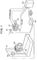
- FIG. 1 The construction of the system according to the first embodiment is shown in Fig. 1.
- numeral 100 denotes a head mounted type image input/output device (called head mounted display (HMD)), which is mounted to the viewer's head for viewing a synthesized image of real space and virtual space.
- Numeral 200 denotes a magnetic transmitter which generates a magnetic field; and 201 and 202, a magnetic sensor which senses variation in the magnetic field generated by the magnetic transmitter 200.
- Numeral 205 denotes a position/orientation tracking device which tracks the position and orientation of the respective magnetic sensors based on sensing results of the magnetic sensors 201 and 202.
- the magnetic sensor 201 mounted to the HMD 100 is used for calculating the viewer's viewpoint position and visual line direction.
- Numeral 300 denotes a simple prototype (simple mockup) which is hand-held and operated by the viewer.
- the simple prototype 300 includes the magnetic sensor 202 as similar to the HMD 100.
- the position and orientation of the magnetic sensor 202 mounted to the simple prototype 300 is known. Therefore, the position/orientation tracking device 205 calculates the position and orientation of the prototype 300 based on the sensing result of the magnetic sensor 202. Assume that the position and orientation of the magnetic sensor 202 have already been tracked physically and inputted in a data processing apparatus 400.
- Numeral 301 denotes a platform for viewing the prototype 300.
- Numeral 101 denotes an image display device incorporated in the HMD 100, which is provided for the left and right eyes.
- Numeral 102 denotes an image input device incorporated in the HMD 100, which is also provided for the left and right eyes.
- Numeral 400 denotes a data processing apparatus, which generates a CG image corresponding to the position and orientation data calculated by the position/orientation tracking device 205, superimposes the CG image on an image inputted by the image input device 102 of the HMD 100, and outputs an obtained synthesized image to the image display device 101 of the HMD 100.
- Numeral 101 in Fig. 2 denotes the image display device shown in Fig. 1, which is constructed with a small liquid crystal display device or the like having the size of about 0.5 to several inches.
- Numeral 103 denotes a free-form surface prism which serves as a lens for enlarging an image in the image display device 101.
- an image displayed on the image display device 101 is provided, e.g., as a 90-inch image at a position 2 m away from the viewer.
- Numeral 102 denotes the image input device shown in Fig. 1, which is configured with an image sensing device such as a CCD camera, CMOS camera or the like.
- Numeral 104 denotes an image sensing system prism serving as a lens for converging light from real space to the image input device 102.
- the image sensing system prism 104 is arranged in the outer side of the free-form surface prism 103 in a manner that the optical axes of both prisms match.
- Numerals 401L and 401R denote an image capturing unit, which captures image data inputted from the image input device 102, converts the image data to a digital signal, and sends the digital signal to the data processing apparatus 400.
- Numeral 404 denotes a position/orientation data input unit which receives position and orientation data of the HMD 100 and simple prototype 300 transmitted from the position/orientation tracking device 205.
- Numeral 405 denotes a position/orientation calculating unit which calculates a relative position relation between the HMD 100 and simple prototype 300 based on the input data from the position/orientation data input unit 404.
- Numeral 406 denotes 3D-CG rendering data which is to be superimposed on an image of the simple prototype 300.
- Numeral 407 denotes a CG rendering unit which calculates the position, size, angle (perspective) and the like for rendering CG data for the left eye and the right eye, based on the relative position relation between the HMD 100 and simple prototype 300 calculated by the position/orientation calculating unit 405, and renders the 3D-CG rendering data 406 based on the calculation result.
- Numerals 402L and 402R denote an image synthesizing unit which superimposes the CG image generated by the CG rendering unit 407 on the real space image data captured by the image capturing units 401L and 401R.
- Numerals 403L and 403R denote an image generating unit which converts the synthesized image data to analogue data and outputs the converted data to the image display device 101.
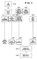
- designed data is generally stored as solid data that is unique to each 3D-CAD system.
- the simple prototype 300 is generated based on the solid data by a rapid prototyping device such as optical modeling (1110).
- the 3D solid data is expressed as a group of geometric parameters of each design parts, the 3D solid data as it is cannot be rendered as CG. Therefore, the 3D solid data is converted to a data form appropriate for 3D-CG rendering (e.g., VRML) (1210).
- virtual space is generated using the 3D-CG rendering data 406 converted in the above-described manner.
- the position/orientation tracking device 205 uses the magnetic transmitter 200 and magnetic sensor 202 to track the position and orientation of the simple prototype 300 in real space (2010). Similarly, using data from the magnetic transmitter 200 and magnetic sensor 201, the position/orientation tracking device 205 tracks the position and orientation of the HMD 100 worn by the viewer in real space (2020). The tracking data obtained by the position/orientation tracking device 205 is inputted to the data processing apparatus 400 through the position/orientation data input unit 404. Then, the position/orientation calculating unit 405 calculates a relative position/orientation relation between the HMD 100 and simple prototype 300 (2030).
- a real space image from the image input device 102 of the HMD 100 is captured by the data processing apparatus 400 through the image capturing unit 401 (3010).
- CG rendering unit 407 CG is rendered using the relative position relation calculated in process 2030 and the 3D-CG rendering data 406, and the rendered CG is developed in a memory (not shown) such as a video buffer (2040).
- the real space image data captured in process 3010 is also developed in the memory such as a video buffer (3020).
- the image synthesizing units 402L and 402R superimpose the CG image generated in process 2040 on the image data developed in process 3020 (4010).
- the synthesized image is converted to a video signal, e.g., analogue signal, by the image generating unit 403 and displayed on the image display device 101 of the HMD 100 (4020).
- image data can be provided in real time.
- An example of the processing result according to this system is shown in Figs. 5A and 5B.
- Fig. 5A shows a real space image (a real image of simple prototype 300) which is inputted by the image input device 102 of the HMD 100.
- Fig. 5B shows an image where a CG image based on CG data is superimposed on the simple prototype 300 in real space, in other words, an image displayed on the image display device 101 of the HMD 100.
- the first embodiment describes as an example an apparatus using magnetism as means for tracking the position and orientation
- other means may be used instead, such as an optical position/orientation tracking device.
- the first embodiment has described, as an example, position orientation tracking using magnetism.
- the tracking precision may become unstable depending on the environment. For instance, if a metal object exists near the magnetic transmitter, the magnetic field is disturbed, resulting in an unstable output value of the magnetic sensor. Furthermore, there is a problem in that, the larger the distance between the magnetic transmitter and the magnetic sensor, the more the tracking precision is deteriorated.
- Such problem regarding tracking precision is not limited to sensors using magnetism, but occurs in a position/orientation tracking device using various methods. For instance, in a case of optical position/orientation tracking means, there is a problem in that if a shielding object exists between a light emitting device and a light receiving device, the tracking becomes unstable, causing an error.
- the mixed reality system corrects the position and orientation using the real space image data captured by the data processing apparatus 400, and improves the tracking precision.
- an image recognition marker is attached to the simple prototype 300, and the marker is used as a characteristic point.
- various types such as a shape marker 310 or a color marker 311 may be considered based on a position/orientation correction algorithm.
- the position/orientation correction method using the characteristic point is described.
- the characteristic point may be of a sticker type marker, having information such as a particular color or shape, which is artificially attached to the simple prototype in real space, or may be of a characteristic part of the shape of the simple prototype.
- Fig. 7 is a schematic view explaining a general correction method of an external parameter (parameter indicative of the position and orientation) of an image input device (camera).
- the point A indicates a predicted position of the characteristic point predicted based on the position and orientation of the image input device (camera) and simple prototype 300; the point B indicates an actual position of the characteristic point; and the point C indicates a viewpoint position of the image input device (camera).
- the positions represented by the points A and B are positions in a camera coordinate system, and the point C is an origin of the image input device (camera) coordinate system.
- the point P indicates a position of the point A on the image sensing surface, and the point Q indicates a position of the point B on the image sensing surface. As shown in Fig.
- each of the vectors is normalized to a vector having the size 1 by the following equation (2).
- indicates the size of the vector v.
- the rotation axis is a straight line which is orthogonal to a plane formed with the vectors v 1 and v 2 , and passes through the camera viewpoint position (point C).
- the direction vector of the rotation axis can be obtained by vector product of the vectors v 1 and v 2 as shown in equation (3) (in reality, normalized vectors (v 1 ', v 2 ') are used).
- v x v 1 ' ⁇ v 2 '
- a correction matrix ⁇ Mc used for correcting the orientation by rotation of the image input device is calculated by the following equation (5):
- This correction matrix is multiplied by the matrix representing the position and orientation of the image input device, thereby correcting the position and orientation of the image input device.
- the point P is displayed at the position of the point Q, and therefore the landmark position on the image sensing surface which is predicted from the position/orientation parameter coincides with the actual position.
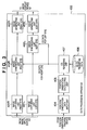
- the second embodiment comprises a marker detecting unit 410 for detecting a marker from image data obtained by the image capturing units 401L and 401R.
- a marker detection result of the marker detecting unit 410 i.e., the coordinate value of the point Q in Fig. 7, is transmitted to the position/orientation calculating unit 405.
- the position and orientation are corrected using the coordinate value of the point Q in the manner described with reference to Fig. 7.
- Other constructions are the same as that of the first embodiment (Fig. 3).
- a marker is attached (1120) to the simple prototype 300 which is generated in process 1110 based on the 3D solid data by a rapid prototyping device such as optical modeling.
- the position data where the marker is attached is recorded (1130).
- the position data of the marker may be three-dimensional data tracked by a separate tracking device.
- the position of the characteristic point can be acquired from CAD data. Further, by generating CAD data so as to form a mark designating the marker's attachment position on the simple prototype, it is possible to acquire marker's position data from the CAD data.
- real space image data is captured by the data processing apparatus 400 in process 3010, and the position of the marker attached to the simple prototype 300 is extracted from the real space image data by the marker detecting unit 410 (3011).
- the relative position/orientation relation between the HMD 100 and simple prototype 300 which has been calculated in process 2030 based on the tracking result of the position/orientation tracking device 205, is corrected (2031).
- CG rendering is performed using the corrected data.
- the image synthesizing unit 402 superimposes (overwrites) the virtual space image (CG image) data on the real space image data, thereby generating a synthesized image.
- CG image virtual space image
- the image synthesizing unit 402 superimposes (overwrites) the virtual space image (CG image) data on the real space image data, thereby generating a synthesized image.
- CG image virtual space image
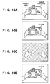
- a contradiction occurs between the depth representations of a CG image and a real object. The contradiction is described in detail with reference to Figs. 10A to 10D.
- Fig. 10A shows an example of real space image data inputted by the image input device 102, which is a simple prototype held by viewer's hands. A part of the hands (thumbs) is shown in front of (before) the prototype. If a CG image corresponding to the simple prototype is superimposed on this image, a synthesized image shown in Fig. 10B is displayed. In other words, the part of the hands that should exist in front of (before) the simple prototype is hidden by the CG image, causing contradiction in depth representation. This presents an image that gives sense of oddness to the viewer.
- the mixed reality system performs image processing on the real space image data captured by the data processing apparatus 400 to eliminate the above-described contradiction of the depth representation. More specifically, the image data (Fig. 10A) obtained by the image input device 102 is subjected to image processing to extract the area of hands. From the extracted hand area, a mask image (Fig. 10C) is generated. A CG image is generated with respect to the area other than the hand area designated by the mask image, and superimposed on the real space image. As a result, the hand area is displayed in front of (before) the prototype as shown in Fig. 10D, thus eliminating the oddness of the depth representation.
- the third embodiment comprises a hand area extracting unit 420 and a hand color data registration data 421 in addition to the construction of the first embodiment (Fig. 3).
- the hand area extracting unit 420 extracts, as a hand area, an area having the color, which is registered in the hand color data registration data 421, from the image data obtained by the image capturing units 401L and 401R.
- the CG rendering unit 407 prohibits CG-image rendering with respect to the hand area extracted by the hand area extracting unit 402.
- Other constructions are the same as that of the first embodiment (Fig. 3).
- Fig. 12 shows a processing flow according to the third embodiment.
- processes 5010 and 5020 are added.
- the hand area extracting unit 420 compares color data of each pixel with the color data of the hand area which has been registered in advance in the hand color data registration data 421. If the pixel matches the color data of the hand area, it is considered that the color of the pixel is a human's flesh color and that the pixel is a hand area (5010). With respect to all pixels, the determination is made as to whether or not the pixel is a hand area. The pixels determined as a hand area are extracted, and only the hand area data is recorded in the memory such as a video buffer for mask image generation (5020).
- CG rendering unit 407 a CG image is generated (2040) for an area masked by the mask image generated in process 5020.
- image synthesizing unit 402 the CG image generated in process 2040 is superimposed on the real space image data (4010).
- the brightness and color tone of the CG generated based on 3D-CAD data are determined based on light source data or the like included in the 3D-CAD data.
- the light source data of the CAD data does not always fit in the real space. For instance, if the real space is dark, the brightness of the CG has to be reduced; otherwise, the CG image looks isolated from the real space and does not create a natural synthesized image.
- various parameters for CG rendering are set based on the real space image data captured by the data processing apparatus 400.
- the CG's brightness and color tones can be matched with the real space environment, making it possible to generate a less odd synthesized image.
- the construction and processing flow of the fourth embodiment are described with reference to Figs. 13 and 14.
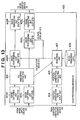
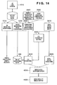
- the fourth embodiment comprises a CG parameter extracting unit 430 in addition to the construction of the first embodiment (Fig. 3). Further in Fig. 14 showing the process according to the fourth embodiment, CG parameter setting process 3012 is added to the processes of the first embodiment.
- the CG parameter extracting unit 430 grasps the real space environment from the real space image data inputted through the image capturing units 401L and 401R, and sets parameters for rendering a CG image, e.g., brightness, color tones and so on (3012).
- a CG image is rendered based on the parameters acquired from the CG parameter extracting unit 430 and the 3D-CG data (2040).
- the image synthesizing unit 402 the CG image is superimposed on the real space image data (4010).
- setting the parameters for rendering a CG image is to change a value of a CG data attribute. For instance, when CG data is rendered, it is necessary to set from where and what kind of illumination is thrown at an object (parameter setting of light in virtual space). In this stage, by setting parameters such as a material of a CG object, a position, intensity and color of the light source that illuminates the CG object, it is possible to adjust the brightness and color tones in CG rendering. Furthermore, in mixed reality (MR), it is necessary to adjust brightness of a CG image in accordance with the brightness of the inputted real space.
- MR mixed reality
- the fourth embodiment captures the real space image as a video image, for instance, an average of the brightness and color tones of the captured image is obtained (or the brightness and color tone of a predetermined area may be obtained), and the aforementioned lighting parameters are adjusted in accordance with the average value, thereby adjusting the brightness and color tones for CG rendering.
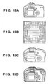
- Fig. 15A shows the simple prototype 300 placed in real space.
- Fig. 15B shows a distortion amount shown in Fig. 15B
- a distorted object shown in Fig. 15C is inputted by the image input device.
- a CG image is superimposed on the distorted image, the CG image does not accurately overlap the prototype in real space as shown in Fig. 15D, resulting in a synthesized image that gives sense of oddness to a viewer.
- the distortion of image data in real space captured by the data processing apparatus 400 is removed by image processing, and a less odd synthesized image is provided.
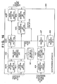
- the construction and processing flow of the data processing apparatus 400 according to the fifth embodiment are described with reference to Figs. 16 and 17.
- the fifth embodiment comprises a real space image distortion correcting unit 440 and distortion amount data 441 in addition to the construction of the first embodiment (Fig. 3). Furthermore, as shown in Fig. 17, distortion correction process 3013 is added to the processes of the first embodiment (Fig. 4).
- the real space image distortion correcting unit 440 corrects a distortion of real space image data. Using the distortion amount data 441 of the image input system which is measured in advance and stored, the correcting unit 440 corrects image data inputted from the image capturing units 401L and 401R (3013). By virtue of this processing, the simple prototype in real space accurately overlaps the CG image, and therefore a viewer can view a natural synthesized image. More specifically, since real space is inputted to the system as image data and the real space image is converted to an image which is appropriate for being synthesized with a virtual space image (CG), it is possible to generate a mixed reality image which is natural to a viewer.
- CG virtual space image
- the mixed reality system it is possible to superimpose 3D-CG data generated by converting 3D-CAD data on an image of a simple prototype (simple mockup) generated by a rapid prototyping device or the like based on the 3D-CAD data with a matched position and orientation, and the synthesized image can be displayed.
- This system realizes both visual evaluation and tactual evaluation, and enables evaluation under the condition close to a finished product.
- real space is inputted to the system as image data and the real space image can be converted to an image appropriate for being synthesized with a virtual space image, it is possible to generate an image which is natural to a viewer.
- an embodiment of the present invention can be achieved by providing a carrier (such as a storage medium or signal) carrying program codes of a software realizing the functions of the above-described embodiments to a computer system or apparatus, reading the program codes, by a computer (CPU or MPU) of the computer system or apparatus, from the carrier, then executing the program.
- a carrier such as a storage medium or signal
- the program codes read from the carrier realize the functions according to the embodiments, and the carrier carrying the program codes constitutes an embodiment of the invention.
- a storage medium such as a flexible disk, hard disk, an optical disk, a magneto-optical disk, CD-ROM, CD-R, a magnetic tape, a non-volatile type memory card, and ROM can be used for providing the program codes.
- an embodiment includes a case where an OS (operating system) or the like working on the computer performs a part or the entire processes in accordance with designations of the program codes and realizes functions according to the above embodiments.
- OS operating system
- an embodiment also includes a case where, after the program codes read from the carrier are written in a function expansion card which is inserted into the computer or in a memory provided in a function expansion unit which is connected to the computer, a CPU or the like contained in the function expansion card or unit performs a part or the entire processes in accordance with designations of the program codes and realizes functions of the above embodiments.
Abstract
Description
- The present invention relates to an image display apparatus and method employed in a mixed reality system, which exhibits a viewer image data in virtual space superimposed on image data in real space at an arbitrary viewpoint.
- The mixed reality system provides a user with a synthesized image, which is obtained by synthesizing a real space image with a virtual space image generated in accordance with a user's viewpoint position, visual line direction, and so forth. The mixed reality system can give a viewer a sense that as if a virtual object really exists in real space. Compared to a conventional virtual reality system (VR system), more realistic and full-scale viewing is possible (refer to Japanese Patent Application Laid-Open No. 11-136706).
- Meanwhile, in the design and production field, designing (shapes and designs) by a three-dimensional CAD is prevailing. The mainstream method of evaluating an object designed by a three-dimensional CAD includes a method that visually evaluates the object by displaying data (solid type) generated by a three-dimensional CAD on a computer screen as three-dimensional computer graphics (hereinafter referred to as a 3D-CG), or a method that visually and tactually evaluates the object by generating a simple prototype (simple mockup) using a rapid prototyping device or the like.
- However, the method of displaying three-dimensional CAD data on a computer screen as a 3D-CG merely allows evaluation in virtual space, and it is impossible to evaluate an object as a full-scale object in real space. Furthermore, the method of generating a simple prototype (simple mockup) by a rapid prototyping device is effective for grasping a rough shape of an object under the constraints of processing precision, materials and so on, but it does not reproduce detailed information, e.g., the detailed design and shape, colors and so on, designed by the 3D-CAD. Therefore, there is a demand for a method that can evaluate design data under the condition close to a finished product.
- An embodiment of the present invention facilitates design evaluation under the condition close to a finished product with the use of a mockup produced as a simple prototype.
- The present invention provides an image display method of superimposing image data of virtual space on image data of real space at an arbitrary viewpoint and exhibiting a superimposed image to a viewer, comprising: an image sensing step of capturing, by an image sensing device, image data of real space including a prototype generated based on three-dimensional CAD data; a tracking step of tracking a position and orientation of the image sensing device and the prototype, and acquiring position/orientation data indicative of the position and orientation of the prototype in an image obtained in the image sensing step; and a synthesizing step of rendering a three-dimensional computer graphic image based on the position/orientation data and the three-dimensional CAD data so as to overlap the prototype in the image obtained in the image sensing step, thereby synthesizing the image with the three-dimensional computer graphic image.
- The present invention provides an image display apparatus for superimposing image data of virtual space on image data of real space at an arbitrary viewpoint and exhibiting a superimposed image to a viewer, comprising: an image sensing unit configured to capture image data of real space including a prototype generated based on three-dimensional CAD data; a tracking unit configured to track a position and orientation of the image sensing unit and the prototype, and acquire position/orientation data indicative of the position and orientation of the prototype in an image obtained by the image sensing unit; and a synthesizing unit configured to render a three-dimensional computer graphic image based on the position/orientation data and the three-dimensional CAD data so as to overlap the prototype in the image obtained by the image sensing unit, thereby synthesizing the image with the three-dimensional computer graphic image.
- Embodiments of the present invention will now be described in detail in accordance with the accompanying drawings, in which like reference characters designate the same or similar parts throughout the figures thereof, and in which:
- Fig. 1 is a view showing a brief construction of a mixed reality system according to the first embodiment;
- Fig. 2 is a view showing a construction of a head mounted type image input/output device (HMD);
- Fig. 3 is a block diagram showing a construction of a data processing apparatus according to the first embodiment;
- Fig. 4 is a diagram showing a processing flow of the data processing apparatus according to the first embodiment;
- Figs. 5A and 5B are explanatory views showing a processing result according to the first embodiment;
- Fig. 6 is an illustration showing an example of a marker attached to a simple prototype according to the second embodiment;
- Fig. 7 is an illustration explaining correction of position/orientation tracking using a characteristic point;
- Fig. 8 is a block diagram showing a construction of a data processing apparatus according to the second embodiment;
- Fig. 9 is a diagram showing a processing flow of the data processing apparatus according to the second embodiment;
- Figs. 10A to 10D are illustration explaining a CG image correction method realized by extracting a hand area;
- Fig. 11 is a block diagram showing a construction of a data processing apparatus according to the third embodiment;
- Fig. 12 is a diagram showing a processing flow of the data processing apparatus according to the third embodiment;
- Fig. 13 is a block diagram showing a construction of a data processing apparatus according to the fourth embodiment;
- Fig. 14 is a diagram showing a processing flow of the data processing apparatus according to the fourth embodiment;
- Figs. 15A to 15D are illustrations explaining an influence of distortion of an image input system;
- Fig. 16 is a block diagram showing a construction of a data processing apparatus according to the fifth embodiment; and
- Fig. 17 is a diagram showing a processing flow of the data processing apparatus according to the fifth embodiment.
-
- In the mixed reality system according to the first embodiment which will be described below, a photographed image of a simple prototype (simple mockup), which is generated by a rapid prototyping device based on three-dimensional CAD data, is superimposed on three-dimensional CG (3D-CG) data generated by converting the same three-dimensional CAD data, and their positions and orientations are matched and displayed in the mixed reality system. This system realizes both visual evaluation and tactual evaluation, thus enabling evaluation under the condition close to a finished product.
- The construction of the system according to the first embodiment is shown in Fig. 1.
- Referring to Fig. 1,
numeral 100 denotes a head mounted type image input/output device (called head mounted display (HMD)), which is mounted to the viewer's head for viewing a synthesized image of real space and virtual space. Numeral 200 denotes a magnetic transmitter which generates a magnetic field; and 201 and 202, a magnetic sensor which senses variation in the magnetic field generated by themagnetic transmitter 200. Numeral 205 denotes a position/orientation tracking device which tracks the position and orientation of the respective magnetic sensors based on sensing results of themagnetic sensors magnetic sensor 201 mounted to the HMD 100 is used for calculating the viewer's viewpoint position and visual line direction. Numeral 300 denotes a simple prototype (simple mockup) which is hand-held and operated by the viewer. Thesimple prototype 300 includes themagnetic sensor 202 as similar to the HMD 100. The position and orientation of themagnetic sensor 202 mounted to thesimple prototype 300 is known. Therefore, the position/orientation tracking device 205 calculates the position and orientation of theprototype 300 based on the sensing result of themagnetic sensor 202. Assume that the position and orientation of themagnetic sensor 202 have already been tracked physically and inputted in adata processing apparatus 400. Numeral 301 denotes a platform for viewing theprototype 300. - Numeral 101 denotes an image display device incorporated in the HMD 100, which is provided for the left and right eyes. Numeral 102 denotes an image input device incorporated in the HMD 100, which is also provided for the left and right eyes. Numeral 400 denotes a data processing apparatus, which generates a CG image corresponding to the position and orientation data calculated by the position/
orientation tracking device 205, superimposes the CG image on an image inputted by theimage input device 102 of theHMD 100, and outputs an obtained synthesized image to theimage display device 101 of theHMD 100. - Next, a detailed construction of the
HMD 100 is described with reference to Fig. 2. Numeral 101 in Fig. 2 denotes the image display device shown in Fig. 1, which is constructed with a small liquid crystal display device or the like having the size of about 0.5 to several inches. Numeral 103 denotes a free-form surface prism which serves as a lens for enlarging an image in theimage display device 101. By these components, an image displayed on theimage display device 101 is provided, e.g., as a 90-inch image at a position 2 m away from the viewer. - Numeral 102 denotes the image input device shown in Fig. 1, which is configured with an image sensing device such as a CCD camera, CMOS camera or the like. Numeral 104 denotes an image sensing system prism serving as a lens for converging light from real space to the
image input device 102. The imagesensing system prism 104 is arranged in the outer side of the free-form surface prism 103 in a manner that the optical axes of both prisms match. By virtue of this arrangement, a parallax between an image inputted by theimage input device 102 and an image displayed on theimage display device 101 is eliminated, and a real space image can be reproduced without giving sense of oddness. - Next, a detailed construction of the
data processing apparatus 400 shown in Fig. 1 is described with reference to Fig. 3. -
Numerals image input device 102, converts the image data to a digital signal, and sends the digital signal to thedata processing apparatus 400. Numeral 404 denotes a position/orientation data input unit which receives position and orientation data of theHMD 100 andsimple prototype 300 transmitted from the position/orientation tracking device 205. Numeral 405 denotes a position/orientation calculating unit which calculates a relative position relation between theHMD 100 andsimple prototype 300 based on the input data from the position/orientationdata input unit 404. - Numeral 406 denotes 3D-CG rendering data which is to be superimposed on an image of the
simple prototype 300.Numeral 407 denotes a CG rendering unit which calculates the position, size, angle (perspective) and the like for rendering CG data for the left eye and the right eye, based on the relative position relation between theHMD 100 andsimple prototype 300 calculated by the position/orientation calculating unit 405, and renders the 3D-CG rendering data 406 based on the calculation result. -
Numerals CG rendering unit 407 on the real space image data captured by theimage capturing units Numerals image display device 101. - The processing flow of the first embodiment having the above-described construction is described with reference to Fig. 4. First, a generation procedure of the
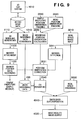
simple prototype 300 and the 3D-CG rendering data 406 based on the 3D-CAD data is described with reference to the chart on the left side of Fig. 4. - In a case of designing shapes and designs by a three-dimensional CAD system (1010), designed data is generally stored as solid data that is unique to each 3D-CAD system. The
simple prototype 300 is generated based on the solid data by a rapid prototyping device such as optical modeling (1110). Meanwhile, since the 3D solid data is expressed as a group of geometric parameters of each design parts, the 3D solid data as it is cannot be rendered as CG. Therefore, the 3D solid data is converted to a data form appropriate for 3D-CG rendering (e.g., VRML) (1210). - In the mixed reality system according to the first embodiment, virtual space is generated using the 3D-
CG rendering data 406 converted in the above-described manner. - Next, a processing procedure of the mixed reality system according to the first embodiment is described with reference to the chart on the right side of Fig. 4.
- Using the
magnetic transmitter 200 andmagnetic sensor 202, the position/orientation tracking device 205 tracks the position and orientation of thesimple prototype 300 in real space (2010). Similarly, using data from themagnetic transmitter 200 andmagnetic sensor 201, the position/orientation tracking device 205 tracks the position and orientation of theHMD 100 worn by the viewer in real space (2020). The tracking data obtained by the position/orientation tracking device 205 is inputted to thedata processing apparatus 400 through the position/orientationdata input unit 404. Then, the position/orientation calculating unit 405 calculates a relative position/orientation relation between theHMD 100 and simple prototype 300 (2030). - In parallel with the above-described
processes image input device 102 of theHMD 100 is captured by thedata processing apparatus 400 through the image capturing unit 401 (3010). In theCG rendering unit 407, CG is rendered using the relative position relation calculated inprocess 2030 and the 3D-CG rendering data 406, and the rendered CG is developed in a memory (not shown) such as a video buffer (2040). - Meanwhile, the real space image data captured in
process 3010 is also developed in the memory such as a video buffer (3020). Theimage synthesizing units process 2040 on the image data developed in process 3020 (4010). The synthesized image is converted to a video signal, e.g., analogue signal, by the image generating unit 403 and displayed on theimage display device 101 of the HMD 100 (4020). - By repeatedly performing the above-described
processes 2010 to 4020 at image update intervals of theimage display device 101 or at rendering update intervals ofCG rendering process 2040, image data can be provided in real time. An example of the processing result according to this system is shown in Figs. 5A and 5B. - Fig. 5A shows a real space image (a real image of simple prototype 300) which is inputted by the
image input device 102 of theHMD 100. Fig. 5B shows an image where a CG image based on CG data is superimposed on thesimple prototype 300 in real space, in other words, an image displayed on theimage display device 101 of theHMD 100. - Although the first embodiment describes as an example an apparatus using magnetism as means for tracking the position and orientation, other means may be used instead, such as an optical position/orientation tracking device.
- The first embodiment has described, as an example, position orientation tracking using magnetism. However, in the position/orientation tracking using magnetism, the tracking precision may become unstable depending on the environment. For instance, if a metal object exists near the magnetic transmitter, the magnetic field is disturbed, resulting in an unstable output value of the magnetic sensor. Furthermore, there is a problem in that, the larger the distance between the magnetic transmitter and the magnetic sensor, the more the tracking precision is deteriorated. Such problem regarding tracking precision is not limited to sensors using magnetism, but occurs in a position/orientation tracking device using various methods. For instance, in a case of optical position/orientation tracking means, there is a problem in that if a shielding object exists between a light emitting device and a light receiving device, the tracking becomes unstable, causing an error.
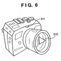
- In view of this, the mixed reality system according to the second embodiment corrects the position and orientation using the real space image data captured by the
data processing apparatus 400, and improves the tracking precision. For instance, as shown in Fig. 6, an image recognition marker is attached to thesimple prototype 300, and the marker is used as a characteristic point. For a marker, various types such as ashape marker 310 or acolor marker 311 may be considered based on a position/orientation correction algorithm. - Hereinafter, the position/orientation correction method using the characteristic point is described. As a general correction method, correcting an external parameter of an image input unit (camera) based on one characteristic point is described. Note that the characteristic point may be of a sticker type marker, having information such as a particular color or shape, which is artificially attached to the simple prototype in real space, or may be of a characteristic part of the shape of the simple prototype.
- Fig. 7 is a schematic view explaining a general correction method of an external parameter (parameter indicative of the position and orientation) of an image input device (camera). In Fig. 7, the point A indicates a predicted position of the characteristic point predicted based on the position and orientation of the image input device (camera) and
simple prototype 300; the point B indicates an actual position of the characteristic point; and the point C indicates a viewpoint position of the image input device (camera). Note that the positions represented by the points A and B are positions in a camera coordinate system, and the point C is an origin of the image input device (camera) coordinate system. The point P indicates a position of the point A on the image sensing surface, and the point Q indicates a position of the point B on the image sensing surface. As shown in Fig. 7, assume that the coordinates of the points P and Q are respectively (xp, yp) and (xq, yq); the width and height of the image sensing surface are represented by w and h; the focal distance of the camera (distance from the image sensing surface to the image input device) is represented by d; v1 denotes a vector from the point C to the point Q; v2 denotes a vector from the point C to the point P; and denotes an angle formed by v1 and v2. - First, a description is provided on a method of changing the orientation from the point B direction to the point A direction by the angle , with the use of one characteristic point (correction method by rotating the image input device).
- Based on the above setting, the vectors v1 and v2 are obtained by the following equation (1):

- Next, each of the vectors is normalized to a vector having the size 1 by the following equation (2). Note that |v| indicates the size of the vector v.

- When the image input device (camera) is rotated herein, the rotation axis is a straight line which is orthogonal to a plane formed with the vectors v1 and v2, and passes through the camera viewpoint position (point C). The direction vector of the rotation axis can be obtained by vector product of the vectors v1 and v2 as shown in equation (3) (in reality, normalized vectors (v1', v2') are used).
- The vector vx is a direction vector of the rotation axis, and its component is (1, m, n). Furthermore, the rotation angle which is formed by the vectors v1 and v2 can be obtained by the following equation (4):
- A correction matrix ΔMc used for correcting the orientation by rotation of the image input device is calculated by the following equation (5):

- This correction matrix is multiplied by the matrix representing the position and orientation of the image input device, thereby correcting the position and orientation of the image input device. In other words, the point P is displayed at the position of the point Q, and therefore the landmark position on the image sensing surface which is predicted from the position/orientation parameter coincides with the actual position. Note, although the above description has been given on a correction method using rotation of the image input device (camera), a method of correcting an error by parallel movement of the image input device can also be employed. Furthermore, a correction method using plural characteristic points can achieve a similar effect. Since the concrete steps of this method are apparent from the above description to those who are skilled in the art, description thereof is omitted.
- Next, the construction and processing flow of the
data processing apparatus 400 in the system according to the second embodiment are described with reference to Figs. 8 and 9. As shown in Fig. 8, the second embodiment comprises amarker detecting unit 410 for detecting a marker from image data obtained by theimage capturing units marker detecting unit 410, i.e., the coordinate value of the point Q in Fig. 7, is transmitted to the position/orientation calculating unit 405. In the position/orientation calculating unit 405, the position and orientation are corrected using the coordinate value of the point Q in the manner described with reference to Fig. 7. Other constructions are the same as that of the first embodiment (Fig. 3). - The processing flow of the second embodiment is now described with reference to Fig. 9. For the same processing as that of the first embodiment (Fig. 4), the same reference numerals are assigned.
- A marker is attached (1120) to the
simple prototype 300 which is generated inprocess 1110 based on the 3D solid data by a rapid prototyping device such as optical modeling. The position data where the marker is attached is recorded (1130). Note that the position data of the marker may be three-dimensional data tracked by a separate tracking device. In a case of utilizing a characteristic point, the position of the characteristic point can be acquired from CAD data. Further, by generating CAD data so as to form a mark designating the marker's attachment position on the simple prototype, it is possible to acquire marker's position data from the CAD data. - In the meantime, in the processing of the mixed reality system, real space image data is captured by the
data processing apparatus 400 inprocess 3010, and the position of the marker attached to thesimple prototype 300 is extracted from the real space image data by the marker detecting unit 410 (3011). Using the marker position data recorded in advance inprocess 1130 and the marker position data extracted from the image data inprocess 3011, the relative position/orientation relation between theHMD 100 andsimple prototype 300, which has been calculated inprocess 2030 based on the tracking result of the position/orientation tracking device 205, is corrected (2031). Inprocess 2040, CG rendering is performed using the corrected data. - In the above-described first and second embodiments, the image synthesizing unit 402 superimposes (overwrites) the virtual space image (CG image) data on the real space image data, thereby generating a synthesized image. In this case, because an object that is supposed to be in front of the CG image is overwritten by the CG image, a contradiction occurs between the depth representations of a CG image and a real object. The contradiction is described in detail with reference to Figs. 10A to 10D.
- Fig. 10A shows an example of real space image data inputted by the
image input device 102, which is a simple prototype held by viewer's hands. A part of the hands (thumbs) is shown in front of (before) the prototype. If a CG image corresponding to the simple prototype is superimposed on this image, a synthesized image shown in Fig. 10B is displayed. In other words, the part of the hands that should exist in front of (before) the simple prototype is hidden by the CG image, causing contradiction in depth representation. This presents an image that gives sense of oddness to the viewer. - In view of this, the mixed reality system according to the third embodiment performs image processing on the real space image data captured by the
data processing apparatus 400 to eliminate the above-described contradiction of the depth representation. More specifically, the image data (Fig. 10A) obtained by theimage input device 102 is subjected to image processing to extract the area of hands. From the extracted hand area, a mask image (Fig. 10C) is generated. A CG image is generated with respect to the area other than the hand area designated by the mask image, and superimposed on the real space image. As a result, the hand area is displayed in front of (before) the prototype as shown in Fig. 10D, thus eliminating the oddness of the depth representation. - The construction and processing flow of the system according to the third embodiment are described with reference to Figs. 11 and 12. As shown in Fig. 11, the third embodiment comprises a hand
area extracting unit 420 and a hand colordata registration data 421 in addition to the construction of the first embodiment (Fig. 3). The handarea extracting unit 420 extracts, as a hand area, an area having the color, which is registered in the hand colordata registration data 421, from the image data obtained by theimage capturing units CG rendering unit 407 prohibits CG-image rendering with respect to the hand area extracted by the hand area extracting unit 402. Other constructions are the same as that of the first embodiment (Fig. 3). - Fig. 12 shows a processing flow according to the third embodiment. In addition to the processes of the first embodiment (Fig. 4), processes 5010 and 5020 are added.
- Upon capturing the real space image data by the
image capturing unit 401 of thedata processing apparatus 400 inprocess 3010, the handarea extracting unit 420 compares color data of each pixel with the color data of the hand area which has been registered in advance in the hand colordata registration data 421. If the pixel matches the color data of the hand area, it is considered that the color of the pixel is a human's flesh color and that the pixel is a hand area (5010). With respect to all pixels, the determination is made as to whether or not the pixel is a hand area. The pixels determined as a hand area are extracted, and only the hand area data is recorded in the memory such as a video buffer for mask image generation (5020). In theCG rendering unit 407, a CG image is generated (2040) for an area masked by the mask image generated inprocess 5020. In the image synthesizing unit 402, the CG image generated inprocess 2040 is superimposed on the real space image data (4010). - By generating a synthesized image in the foregoing manner, a real space image which is supposed to be in front of (before) CG data can be displayed in front of (before) the CG data. Therefore, it is possible to eliminate the oddness of the depth representation.
- In the first to third embodiments, the brightness and color tone of the CG generated based on 3D-CAD data are determined based on light source data or the like included in the 3D-CAD data. However, the light source data of the CAD data does not always fit in the real space. For instance, if the real space is dark, the brightness of the CG has to be reduced; otherwise, the CG image looks isolated from the real space and does not create a natural synthesized image. In view of this, according to the fourth embodiment, when a CG image is superimposed on a real space image, various parameters for CG rendering are set based on the real space image data captured by the
data processing apparatus 400. As a result, the CG's brightness and color tones can be matched with the real space environment, making it possible to generate a less odd synthesized image. Hereinafter, the construction and processing flow of the fourth embodiment are described with reference to Figs. 13 and 14. - As shown in Fig. 13, the fourth embodiment comprises a CG
parameter extracting unit 430 in addition to the construction of the first embodiment (Fig. 3). Further in Fig. 14 showing the process according to the fourth embodiment, CGparameter setting process 3012 is added to the processes of the first embodiment. The CGparameter extracting unit 430 grasps the real space environment from the real space image data inputted through theimage capturing units CG rendering unit 407, a CG image is rendered based on the parameters acquired from the CGparameter extracting unit 430 and the 3D-CG data (2040). In the image synthesizing unit 402, the CG image is superimposed on the real space image data (4010). - To be more specific, setting the parameters for rendering a CG image, e.g., brightness, color tones and so on, is to change a value of a CG data attribute.
For instance, when CG data is rendered, it is necessary to set from where and what kind of illumination is thrown at an object (parameter setting of light in virtual space). In this stage, by setting parameters such as a material of a CG object, a position, intensity and color of the light source that illuminates the CG object, it is possible to adjust the brightness and color tones in CG rendering. Furthermore, in mixed reality (MR), it is necessary to adjust brightness of a CG image in accordance with the brightness of the inputted real space. For instance, if the real space is rather dark, rather dark setting is applied to the CG object. When they are badly balanced, only the CG object becomes prominent in the mixed reality, or the CG object is submerged in the mixed reality. Since the fourth embodiment captures the real space image as a video image, for instance, an average of the brightness and color tones of the captured image is obtained (or the brightness and color tone of a predetermined area may be obtained), and the aforementioned lighting parameters are adjusted in accordance with the average value, thereby adjusting the brightness and color tones for CG rendering. - As described above, according to the fourth embodiment, by extracting parameters used for CG rendering from real space data, it is possible to generate a synthesized image that matches the real space environment.
- Since a real space image inputted from the
image input device 102 goes through the imagesensing system prism 104, there is a possibility that the image includes optical distortion. For instance, Fig. 15A shows thesimple prototype 300 placed in real space. When thesimple prototype 300 goes through the imagesensing system prism 104 having a distortion amount shown in Fig. 15B, a distorted object shown in Fig. 15C is inputted by the image input device. If a CG image is superimposed on the distorted image, the CG image does not accurately overlap the prototype in real space as shown in Fig. 15D, resulting in a synthesized image that gives sense of oddness to a viewer. - In the mixed reality system according to the fifth embodiment, the distortion of image data in real space captured by the
data processing apparatus 400 is removed by image processing, and a less odd synthesized image is provided. The construction and processing flow of thedata processing apparatus 400 according to the fifth embodiment are described with reference to Figs. 16 and 17. - As shown in Fig. 16, the fifth embodiment comprises a real space image
distortion correcting unit 440 anddistortion amount data 441 in addition to the construction of the first embodiment (Fig. 3). Furthermore, as shown in Fig. 17,distortion correction process 3013 is added to the processes of the first embodiment (Fig. 4). - The real space image
distortion correcting unit 440 corrects a distortion of real space image data. Using thedistortion amount data 441 of the image input system which is measured in advance and stored, the correctingunit 440 corrects image data inputted from theimage capturing units - Note that each of the above-described embodiments can be realized independently, or in appropriate combination.
- As has been described above, in the mixed reality system according to each of the above embodiments, it is possible to superimpose 3D-CG data generated by converting 3D-CAD data on an image of a simple prototype (simple mockup) generated by a rapid prototyping device or the like based on the 3D-CAD data with a matched position and orientation, and the synthesized image can be displayed. This system realizes both visual evaluation and tactual evaluation, and enables evaluation under the condition close to a finished product. Furthermore, since real space is inputted to the system as image data and the real space image can be converted to an image appropriate for being synthesized with a virtual space image, it is possible to generate an image which is natural to a viewer.
- Further, an embodiment of the present invention can be achieved by providing a carrier (such as a storage medium or signal) carrying program codes of a software realizing the functions of the above-described embodiments to a computer system or apparatus, reading the program codes, by a computer (CPU or MPU) of the computer system or apparatus, from the carrier, then executing the program.
- In this case, the program codes read from the carrier realize the functions according to the embodiments, and the carrier carrying the program codes constitutes an embodiment of the invention.
- A storage medium, such as a flexible disk, hard disk, an optical disk, a magneto-optical disk, CD-ROM, CD-R, a magnetic tape, a non-volatile type memory card, and ROM can be used for providing the program codes.
- Furthermore, besides aforesaid functions according to the above embodiments are realized by executing the program codes which are read by a computer, an embodiment includes a case where an OS (operating system) or the like working on the computer performs a part or the entire processes in accordance with designations of the program codes and realizes functions according to the above embodiments.
- Furthermore, an embodiment also includes a case where, after the program codes read from the carrier are written in a function expansion card which is inserted into the computer or in a memory provided in a function expansion unit which is connected to the computer, a CPU or the like contained in the function expansion card or unit performs a part or the entire processes in accordance with designations of the program codes and realizes functions of the above embodiments.
- According to the above-described configuration of the embodiments, it is possible to superimpose a computer graphic image generated based on 3D-CAD data on a real image of a simple prototype generated based on the 3D-CAD data, and display the synthesized image. Therefore, design data can be evaluated under the condition close to a finished product.
- The present invention is not limited to the above embodiments and various changes and modifications can be made.
Claims (14)
- An image display method of superimposing image data of virtual space on image data of real space at an arbitrary viewpoint and exhibiting a superimposed image to a viewer, characterized by comprising:an image sensing step of capturing, by an image sensing device, image data of real space including a prototype generated based on three-dimensional CAD data;a tracking step of tracking a position and orientation of the image sensing device and the prototype, and acquiring position/orientation data indicative of the position and orientation of the prototype in an image obtained in said image sensing step; anda synthesizing step of rendering a three-dimensional computer graphic image based on the position/orientation data and the three-dimensional CAD data so as to overlap the prototype in the image obtained in said image sensing step, thereby synthesizing the image with the three-dimensional computer graphic image.
- The method according to claim 1, characterized by further comprising a generating step of generating three-dimensional computer graphics data based on the three-dimensional CAD data and storing the generated data,
characterized in that in said synthesizing step, a three-dimensional computer graphic image is rendered using the three-dimensional computer graphics data. - The method according to claim 1, characterized by further comprising a characteristic point extracting step of extracting a characteristic point, whose three-dimensional position on the prototype is known, from the image obtained in said image sensing step,
characterized in that in said tracking step, relative position/orientation data of the prototype and the image sensing device in the image obtained in said image sensing step is corrected based on a position of the characteristic point extracted in said characteristic point extracting step. - The method according to claim 1, characterized by further comprising an area extracting step of extracting an area, having predetermined color data, from the image obtained in said image sensing step,
characterized in that in said synthesizing step, rendering the three-dimensional computer graphic image is prohibited in the area extracted in said area extracting step. - The method according to claim 1, characterized by further comprising a parameter generating step of generating a rendering parameter for the three-dimensional computer graphic image based on the image obtained in said image sensing step,
characterized in that in said synthesizing step, the three-dimensional computer graphic image is rendered using the rendering parameter generated in said parameter generating step. - The method according to claim 1, characterized by further comprising an image correcting step of correcting the image data of real space, obtained in said image sensing step, based on a distortion amount of the image sensing device stored in advance.
- An image display apparatus for superimposing image data of virtual space on image data of real space at an arbitrary viewpoint and exhibiting a superimposed image to a viewer, characterized by comprising:an image sensing unit configured to capture image data of real space including a prototype generated based on three-dimensional CAD data;a tracking unit configured to track a position and orientation of said image sensing unit and the prototype, and acquire position/orientation data indicative of the position and orientation of the prototype in an image obtained by said image sensing unit; anda synthesizing unit configured to render a three-dimensional computer graphic image based on the position/orientation data and the three-dimensional CAD data so as to overlap the prototype in the image obtained by said image sensing unit, thereby synthesizing the image with the three-dimensional computer graphic image.
- The apparatus according to claim 7, characterized by further comprising a characteristic point extracting unit configured to extract a characteristic point, whose three-dimensional position on the prototype is known, from the image obtained by said image sensing unit,
characterized in that said tracking unit corrects relative position/orientation data of the prototype and the image sensing unit in the image, obtained by said image sensing unit, based on a position of the characteristic point extracted by said characteristic point extracting unit. - The apparatus according to claim 7, characterized by further comprising an area extracting unit configured to extract an area, having predetermined color data, from the image obtained by said image sensing unit,
characterized in that said synthesizing unit prohibits rendering the three-dimensional computer graphic image in the area extracted by said area extracting unit. - The apparatus according to claim 7, characterized by further comprising a parameter generating unit configured to generate a rendering parameter for the three-dimensional computer graphic image based on the image obtained by said image sensing unit,
characterized in that said synthesizing unit renders the three-dimensional computer graphic image using the rendering parameter generated by said parameter generating unit. - The apparatus according to claim 7, characterized by further comprising an image correcting unit configured to correct the image data of real space, obtained by said image sensing unit, based on a distortion amount of said image sensing unit stored in advance.
- A control program for realizing by a computer the image display method described in claim 1.
- A storage medium storing a control program for realizing by a computer the image display method described in claim 1.
- A method of generating superimposed image data of an object comprising virtual image data of the object and real image data of the object, the method comprising:receiving image data defining an image captured by an image sensing device of real space including an object generated using three-dimensional computer-aided-design data;receiving data defining the position and orientation of the image sensing device and data defining the position and orientation of the object;determining the relative position and orientation of the image sensing device and the object;rendering a virtual image of the object from a viewing position and direction corresponding to the determined relative position and orientation of the image sensing device and object using the three-dimensional computer-aided-design data from which the object was generated, or data derived therefrom; andcombining the rendered virtual image data and the received image data captured by the image sensing device to generate superimposed image data of the object.
Applications Claiming Priority (2)
| Application Number | Priority Date | Filing Date | Title |
|---|---|---|---|
| JP2003341628 | 2003-09-30 | ||
| JP2003341628A JP4401727B2 (en) | 2003-09-30 | 2003-09-30 | Image display apparatus and method |
Publications (3)
| Publication Number | Publication Date |
|---|---|
| EP1521482A2 true EP1521482A2 (en) | 2005-04-06 |
| EP1521482A3 EP1521482A3 (en) | 2015-06-03 |
| EP1521482B1 EP1521482B1 (en) | 2019-09-18 |
Family
ID=34309072
Family Applications (1)
| Application Number | Title | Priority Date | Filing Date |
|---|---|---|---|
| EP04255986.4A Expired - Fee Related EP1521482B1 (en) | 2003-09-30 | 2004-09-29 | Image display apparatus and method |
Country Status (4)
| Country | Link |
|---|---|
| US (1) | US7312795B2 (en) |
| EP (1) | EP1521482B1 (en) |
| JP (1) | JP4401727B2 (en) |
| CN (1) | CN1320423C (en) |
Cited By (18)
| Publication number | Priority date | Publication date | Assignee | Title |
|---|---|---|---|---|
| WO2007017596A2 (en) | 2005-08-09 | 2007-02-15 | Total Immersion | Device for visualising a virtual passenger compartment of a vehicle in a real situation |
| WO2007017595A2 (en) * | 2005-08-09 | 2007-02-15 | Total Immersion | Method and devices for visualising a real passenger compartment in a synthesis environment |
| EP1761075A2 (en) | 2005-08-29 | 2007-03-07 | Canon Kabushiki Kaisha | Stereoscopic display device and control method therefor |
| EP2512141A1 (en) * | 2011-04-15 | 2012-10-17 | Sony Computer Entertainment Europe Ltd. | System and method of user interaction in augmented reality |
| US8380586B2 (en) | 2005-12-01 | 2013-02-19 | International Business Machines Corporation | Consumer representation rendering with selected merchandise |
| WO2015004916A3 (en) * | 2013-07-11 | 2015-03-05 | Seiko Epson Corporation | Head mounted display device and control method for head mounted display device |
| US20160026242A1 (en) | 2014-07-25 | 2016-01-28 | Aaron Burns | Gaze-based object placement within a virtual reality environment |
| EP2981079A4 (en) * | 2013-03-28 | 2016-12-28 | Sony Corp | Image processing device and method, and program |
| EP2434458A3 (en) * | 2010-09-27 | 2017-02-22 | Nintendo Co., Ltd. | Image processing program, apparatus, system, and method for mixed reality |
| US9645397B2 (en) | 2014-07-25 | 2017-05-09 | Microsoft Technology Licensing, Llc | Use of surface reconstruction data to identify real world floor |
| WO2017213862A1 (en) * | 2016-06-06 | 2017-12-14 | Microsoft Technology Licensing, Llc | Optically augmenting electromagnetic tracking in mixed reality |
| US9858720B2 (en) | 2014-07-25 | 2018-01-02 | Microsoft Technology Licensing, Llc | Three-dimensional mixed-reality viewport |
| US9865089B2 (en) | 2014-07-25 | 2018-01-09 | Microsoft Technology Licensing, Llc | Virtual reality environment with real world objects |
| EP2717227A3 (en) * | 2012-10-02 | 2018-02-07 | Nintendo Co., Ltd. | Image processing program, image processing device, image processing system, and image processing method |
| US9904055B2 (en) | 2014-07-25 | 2018-02-27 | Microsoft Technology Licensing, Llc | Smart placement of virtual objects to stay in the field of view of a head mounted display |
| US10254546B2 (en) | 2016-06-06 | 2019-04-09 | Microsoft Technology Licensing, Llc | Optically augmenting electromagnetic tracking in mixed reality |
| US10311638B2 (en) | 2014-07-25 | 2019-06-04 | Microsoft Technology Licensing, Llc | Anti-trip when immersed in a virtual reality environment |
| US10451875B2 (en) | 2014-07-25 | 2019-10-22 | Microsoft Technology Licensing, Llc | Smart transparency for virtual objects |
Families Citing this family (59)
| Publication number | Priority date | Publication date | Assignee | Title |
|---|---|---|---|---|
| JP3991020B2 (en) * | 2003-09-30 | 2007-10-17 | キヤノン株式会社 | Image display method and image display system |
| JP4708752B2 (en) * | 2004-09-28 | 2011-06-22 | キヤノン株式会社 | Information processing method and apparatus |
| JP4661512B2 (en) * | 2004-11-05 | 2011-03-30 | 株式会社日立製作所 | Remote maintenance system, monitoring center computer and maintenance instruction method |
| US8585476B2 (en) | 2004-11-16 | 2013-11-19 | Jeffrey D Mullen | Location-based games and augmented reality systems |
| US7535498B2 (en) * | 2005-01-03 | 2009-05-19 | Cnoga Medical Ltd. | Electronic viewing device |
| JP4726194B2 (en) * | 2005-04-01 | 2011-07-20 | キヤノン株式会社 | Calibration method and apparatus |
| DE602005013752D1 (en) * | 2005-05-03 | 2009-05-20 | Seac02 S R L | Augmented reality system with identification of the real marking of the object |
| JP2006318015A (en) * | 2005-05-10 | 2006-11-24 | Sony Corp | Image processing device, image processing method, image display system, and program |
| JP4832013B2 (en) * | 2005-07-05 | 2011-12-07 | 富士フイルム株式会社 | Image blur correction device |
| JP4574473B2 (en) | 2005-07-11 | 2010-11-04 | キヤノン株式会社 | Information processing apparatus and method |
| US7551179B2 (en) * | 2005-08-10 | 2009-06-23 | Seiko Epson Corporation | Image display apparatus and image adjusting method |
| JP4795091B2 (en) | 2006-04-21 | 2011-10-19 | キヤノン株式会社 | Information processing method and apparatus |
| EP1865455A1 (en) * | 2006-06-07 | 2007-12-12 | Seac02 S.r.l. | A virtual advertising system |
| EP1887526A1 (en) * | 2006-08-11 | 2008-02-13 | Seac02 S.r.l. | A digitally-augmented reality video system |
| JP4926826B2 (en) * | 2007-05-25 | 2012-05-09 | キヤノン株式会社 | Information processing method and information processing apparatus |
| DE102007033486B4 (en) * | 2007-07-18 | 2010-06-17 | Metaio Gmbh | Method and system for mixing a virtual data model with an image generated by a camera or a presentation device |
| JP4600515B2 (en) * | 2008-05-07 | 2010-12-15 | ソニー株式会社 | Information presenting apparatus, information presenting method, imaging apparatus, and computer program |
| JP2010033367A (en) * | 2008-07-29 | 2010-02-12 | Canon Inc | Information processor and information processing method |
| US9600067B2 (en) * | 2008-10-27 | 2017-03-21 | Sri International | System and method for generating a mixed reality environment |
| JP2011085769A (en) * | 2009-10-15 | 2011-04-28 | Canon Inc | Imaging display device |
| US8363919B2 (en) * | 2009-11-25 | 2013-01-29 | Imaging Sciences International Llc | Marker identification and processing in x-ray images |
| US9082036B2 (en) * | 2009-11-25 | 2015-07-14 | Dental Imaging Technologies Corporation | Method for accurate sub-pixel localization of markers on X-ray images |
| US9826942B2 (en) * | 2009-11-25 | 2017-11-28 | Dental Imaging Technologies Corporation | Correcting and reconstructing x-ray images using patient motion vectors extracted from marker positions in x-ray images |
| CN101719274B (en) * | 2009-11-25 | 2011-11-02 | 中国人民解放军第四军医大学 | Three-dimensional texture analyzing method of medicinal image data |
| US9082182B2 (en) * | 2009-11-25 | 2015-07-14 | Dental Imaging Technologies Corporation | Extracting patient motion vectors from marker positions in x-ray images |
| US9082177B2 (en) * | 2009-11-25 | 2015-07-14 | Dental Imaging Technologies Corporation | Method for tracking X-ray markers in serial CT projection images |
| US8422852B2 (en) | 2010-04-09 | 2013-04-16 | Microsoft Corporation | Automated story generation |
| JP5377768B2 (en) * | 2010-06-30 | 2013-12-25 | 富士フイルム株式会社 | Image processing method and apparatus |
| JP5574854B2 (en) * | 2010-06-30 | 2014-08-20 | キヤノン株式会社 | Information processing system, information processing apparatus, information processing method, and program |
| JP5658500B2 (en) | 2010-07-26 | 2015-01-28 | キヤノン株式会社 | Information processing apparatus and control method thereof |
| KR101269773B1 (en) * | 2010-12-13 | 2013-05-30 | 주식회사 팬택 | Terminal and method for providing augmented reality |
| WO2012124250A1 (en) * | 2011-03-15 | 2012-09-20 | パナソニック株式会社 | Object control device, object control method, object control program, and integrated circuit |
| JP5145444B2 (en) * | 2011-06-27 | 2013-02-20 | 株式会社コナミデジタルエンタテインメント | Image processing apparatus, image processing apparatus control method, and program |
| US9437005B2 (en) * | 2011-07-08 | 2016-09-06 | Canon Kabushiki Kaisha | Information processing apparatus and information processing method |
| US9576402B2 (en) * | 2011-11-08 | 2017-02-21 | Panasonic Intellectual Property Management Co., Ltd. | Image processing device and image processing method |
| GB201208088D0 (en) * | 2012-05-09 | 2012-06-20 | Ncam Sollutions Ltd | Ncam |
| JP6041604B2 (en) * | 2012-09-27 | 2016-12-14 | 京セラ株式会社 | Display device, control system, and control program |
| US9508146B2 (en) * | 2012-10-31 | 2016-11-29 | The Boeing Company | Automated frame of reference calibration for augmented reality |
| US8761448B1 (en) | 2012-12-13 | 2014-06-24 | Intel Corporation | Gesture pre-processing of video stream using a markered region |
| US9292103B2 (en) * | 2013-03-13 | 2016-03-22 | Intel Corporation | Gesture pre-processing of video stream using skintone detection |
| JP6138566B2 (en) * | 2013-04-24 | 2017-05-31 | 川崎重工業株式会社 | Component mounting work support system and component mounting method |
| CN103353663B (en) | 2013-06-28 | 2016-08-10 | 北京智谷睿拓技术服务有限公司 | Imaging adjusting apparatus and method |
| CN103353677B (en) | 2013-06-28 | 2015-03-11 | 北京智谷睿拓技术服务有限公司 | Imaging device and method thereof |
| CN103353667B (en) | 2013-06-28 | 2015-10-21 | 北京智谷睿拓技术服务有限公司 | Imaging adjustment Apparatus and method for |
| FR3008210B1 (en) * | 2013-07-03 | 2016-12-09 | Snecma | METHOD AND SYSTEM FOR INCREASED REALITY FOR SUPERVISION |
| CN103424891B (en) | 2013-07-31 | 2014-12-17 | 北京智谷睿拓技术服务有限公司 | Imaging device and method |
| CN103431840B (en) | 2013-07-31 | 2016-01-20 | 北京智谷睿拓技术服务有限公司 | Eye optical parameter detecting system and method |
| CN103431980A (en) | 2013-08-22 | 2013-12-11 | 北京智谷睿拓技术服务有限公司 | Eyesight protection imaging system and method |
| CN103439801B (en) | 2013-08-22 | 2016-10-26 | 北京智谷睿拓技术服务有限公司 | Sight protectio imaging device and method |
| CN103500331B (en) | 2013-08-30 | 2017-11-10 | 北京智谷睿拓技术服务有限公司 | Based reminding method and device |
| CN103605208B (en) * | 2013-08-30 | 2016-09-28 | 北京智谷睿拓技术服务有限公司 | content projection system and method |
| CN103558909B (en) | 2013-10-10 | 2017-03-29 | 北京智谷睿拓技术服务有限公司 | Interaction projection display packing and interaction projection display system |
| US9914222B2 (en) | 2015-02-05 | 2018-03-13 | Canon Kabushiki Kaisha | Information processing apparatus, control method thereof, and computer readable storage medium that calculate an accuracy of correspondence between a model feature and a measurement data feature and collate, based on the accuracy, a geometric model and an object in an image |
| CN105068649A (en) * | 2015-08-12 | 2015-11-18 | 深圳市埃微信息技术有限公司 | Binocular gesture recognition device and method based on virtual reality helmet |
| US10535193B2 (en) * | 2015-09-08 | 2020-01-14 | Canon Kabushiki Kaisha | Image processing apparatus, image synthesizing apparatus, image processing system, image processing method, and storage medium |
| CN109477966B (en) | 2016-02-18 | 2022-06-03 | 苹果公司 | Head mounted display for virtual reality and mixed reality with inside-outside position tracking, user body tracking, and environment tracking |
| JP6470323B2 (en) | 2017-01-23 | 2019-02-13 | ファナック株式会社 | Information display system |
| DE112018005075T5 (en) * | 2017-10-30 | 2020-08-06 | Sony Corporation | INFORMATION PROCESSING DEVICE, INFORMATION PROCESSING PROCESS AND PROGRAM |
| US11899214B1 (en) | 2018-09-18 | 2024-02-13 | Apple Inc. | Head-mounted device with virtually shifted component locations using a double-folded light path |
Citations (2)
| Publication number | Priority date | Publication date | Assignee | Title |
|---|---|---|---|---|
| US20020060648A1 (en) * | 2000-11-17 | 2002-05-23 | Taichi Matsui | Image-display control apparatus |
| US20030113018A1 (en) * | 2001-07-18 | 2003-06-19 | Nefian Ara Victor | Dynamic gesture recognition from stereo sequences |
Family Cites Families (13)
| Publication number | Priority date | Publication date | Assignee | Title |
|---|---|---|---|---|
| IL119831A (en) * | 1996-12-15 | 2002-12-01 | Cognitens Ltd | Apparatus and method for 3d surface geometry reconstruction |
| JP3450704B2 (en) | 1997-09-01 | 2003-09-29 | キヤノン株式会社 | Position and orientation detection apparatus and information processing method |
| US6522312B2 (en) | 1997-09-01 | 2003-02-18 | Canon Kabushiki Kaisha | Apparatus for presenting mixed reality shared among operators |
| JP3377465B2 (en) * | 1999-04-08 | 2003-02-17 | ファナック株式会社 | Image processing device |
| EP1060772B1 (en) * | 1999-06-11 | 2012-02-01 | Canon Kabushiki Kaisha | Apparatus and method to represent mixed reality space shared by plural operators, game apparatus using mixed reality apparatus and interface method thereof |
| US6330356B1 (en) * | 1999-09-29 | 2001-12-11 | Rockwell Science Center Llc | Dynamic visual registration of a 3-D object with a graphical model |
| US6803928B2 (en) * | 2000-06-06 | 2004-10-12 | Fraunhofer-Gesellschaft Zur Foerderung Der Angewandten Forschung E.V. | Extended virtual table: an optical extension for table-like projection systems |
| US20040104935A1 (en) * | 2001-01-26 | 2004-06-03 | Todd Williamson | Virtual reality immersion system |
| JP2005501630A (en) * | 2001-09-05 | 2005-01-20 | ギブン・イメージング・リミテッド | System and method for three-dimensional display of body lumen |
| US20030076980A1 (en) * | 2001-10-04 | 2003-04-24 | Siemens Corporate Research, Inc.. | Coded visual markers for tracking and camera calibration in mobile computing systems |
| JP4004316B2 (en) | 2002-03-20 | 2007-11-07 | 株式会社トプコン | Surveying device and method for acquiring image data using surveying device |
| JP4445182B2 (en) | 2002-03-29 | 2010-04-07 | パイオニア株式会社 | Speaker device |
| CN100398083C (en) | 2002-08-30 | 2008-07-02 | 延自强 | Virtual reality acupuncture point location method and system |
-
2003
- 2003-09-30 JP JP2003341628A patent/JP4401727B2/en not_active Expired - Fee Related
-
2004
- 2004-09-22 US US10/945,994 patent/US7312795B2/en active Active
- 2004-09-29 CN CNB2004100806635A patent/CN1320423C/en not_active Expired - Fee Related
- 2004-09-29 EP EP04255986.4A patent/EP1521482B1/en not_active Expired - Fee Related
Patent Citations (2)
| Publication number | Priority date | Publication date | Assignee | Title |
|---|---|---|---|---|
| US20020060648A1 (en) * | 2000-11-17 | 2002-05-23 | Taichi Matsui | Image-display control apparatus |
| US20030113018A1 (en) * | 2001-07-18 | 2003-06-19 | Nefian Ara Victor | Dynamic gesture recognition from stereo sequences |
Non-Patent Citations (6)
| Title |
|---|
| Carsten Huschka,: "AR-based prototyping in engineering and design (Augmented MockUp)", , 2002, XP002541694, Retrieved from the Internet: URL:http://studierstube.icg.tu-graz.ac.at/ismar2002/demos/ismar_huschka.pdf [retrieved on 2009-08-17] * |
| Carsten Huschka,: "Augmented Design Review", , June 2003 (2003-06), XP002541695, Retrieved from the Internet: URL:http://www.arvika.de/www/pdf/flyer2003_3c.pdf [retrieved on 2009-08-17] * |
| FIORENTINO M ET AL: "Spacedesign: a mixed reality workspace for aesthetic industrial design", MIXED AND AUGMENTED REALITY, 2002. ISMAR 2002. PROCEEDINGS. INTERNATIO NAL SYMPOSIUM ON SEPT. 30 - OCT. 1, 2002, PISCATAWAY, NJ, USA,IEEE, 30 September 2002 (2002-09-30), pages 86-318, XP010620945, ISBN: 978-0-7695-1781-0 * |
| FRUEND J ET AL: "AR-based product design in automobile industry", AGUMENTED REALITY TOOLKIT, THE FIRST IEEE INTERNATIONAL WORKSHOP SEP. 29, 2002, PISCATAWAY, NJ, USA,IEEE, 1 January 2002 (2002-01-01), pages 48-49, XP010620342, ISBN: 978-0-7803-7680-9 * |
| KATO H ET AL: "Virtual object manipulation on a table-top AR environment", AUGMENTED REALITY, 2000. (ISAR 2000). PROCEEDINGS. IEEE AND ACM INTERN ATIONAL SYMPOSIUM ON MUNICH, GERMANY 5-6 OCT. 2000, PISCATAWAY, NJ, USA,IEEE, US, 5 October 2000 (2000-10-05), pages 111-119, XP010520320, ISBN: 978-0-7695-0846-7 * |
| SANTOS, P.; FLEISCH, T.; GRAF, H.; STORK, A.: "3D interactive augmented reality in early stages of product design", HCI INTERNATIONAL 2003. PROCEEDINGS OF THE 10TH INTERNATIONAL CONFERENCE ON HUMAN-COMPUTER INTERACTION, vol. 4, 1 September 2003 (2003-09-01), pages 1203-1207, XP002541696, Mahwah/NJ ISBN: 0-8058-4933-5 * |
Cited By (33)
| Publication number | Priority date | Publication date | Assignee | Title |
|---|---|---|---|---|
| WO2007017596A2 (en) | 2005-08-09 | 2007-02-15 | Total Immersion | Device for visualising a virtual passenger compartment of a vehicle in a real situation |
| WO2007017596A3 (en) * | 2005-08-09 | 2007-04-05 | Total Immersion | Device for visualising a virtual passenger compartment of a vehicle in a real situation |
| WO2007017595A2 (en) * | 2005-08-09 | 2007-02-15 | Total Immersion | Method and devices for visualising a real passenger compartment in a synthesis environment |
| WO2007017595A3 (en) * | 2005-08-09 | 2007-04-05 | Total Immersion | Method and devices for visualising a real passenger compartment in a synthesis environment |
| EP1761075A2 (en) | 2005-08-29 | 2007-03-07 | Canon Kabushiki Kaisha | Stereoscopic display device and control method therefor |
| EP1761075A3 (en) * | 2005-08-29 | 2012-01-11 | Canon Kabushiki Kaisha | Stereoscopic display device and control method therefor |
| US8885027B2 (en) | 2005-08-29 | 2014-11-11 | Canon Kabushiki Kaisha | Stereoscopic display device and control method therefor |
| US9779447B2 (en) | 2005-12-01 | 2017-10-03 | International Business Machines Corporation | Consumer representation rendering with selected merchandise |
| US8768786B2 (en) | 2005-12-01 | 2014-07-01 | International Business Machines Corporation | Consumer representation rendering with selected merchandise |
| US8380586B2 (en) | 2005-12-01 | 2013-02-19 | International Business Machines Corporation | Consumer representation rendering with selected merchandise |
| EP2434458A3 (en) * | 2010-09-27 | 2017-02-22 | Nintendo Co., Ltd. | Image processing program, apparatus, system, and method for mixed reality |
| EP2512141A1 (en) * | 2011-04-15 | 2012-10-17 | Sony Computer Entertainment Europe Ltd. | System and method of user interaction in augmented reality |
| US8941687B2 (en) | 2011-04-15 | 2015-01-27 | Sony Computer Entertainment Europe Limited | System and method of user interaction for augmented reality |
| EP2717227A3 (en) * | 2012-10-02 | 2018-02-07 | Nintendo Co., Ltd. | Image processing program, image processing device, image processing system, and image processing method |
| US10365767B2 (en) | 2013-03-28 | 2019-07-30 | Sony Corporation | Augmented reality image processing apparatus and method, and program |
| EP2981079A4 (en) * | 2013-03-28 | 2016-12-28 | Sony Corp | Image processing device and method, and program |
| US9971155B2 (en) | 2013-07-11 | 2018-05-15 | Seiko Epson Corporation | Head mounted display device and control method for head mounted display device |
| RU2643649C2 (en) * | 2013-07-11 | 2018-02-02 | Сейко Эпсон Корпорейшн | Head-mounted display device and method of controlling head-mounted display device |
| WO2015004916A3 (en) * | 2013-07-11 | 2015-03-05 | Seiko Epson Corporation | Head mounted display device and control method for head mounted display device |
| US10096168B2 (en) | 2014-07-25 | 2018-10-09 | Microsoft Technology Licensing, Llc | Three-dimensional mixed-reality viewport |
| US10416760B2 (en) | 2014-07-25 | 2019-09-17 | Microsoft Technology Licensing, Llc | Gaze-based object placement within a virtual reality environment |
| US9858720B2 (en) | 2014-07-25 | 2018-01-02 | Microsoft Technology Licensing, Llc | Three-dimensional mixed-reality viewport |
| US9645397B2 (en) | 2014-07-25 | 2017-05-09 | Microsoft Technology Licensing, Llc | Use of surface reconstruction data to identify real world floor |
| US9904055B2 (en) | 2014-07-25 | 2018-02-27 | Microsoft Technology Licensing, Llc | Smart placement of virtual objects to stay in the field of view of a head mounted display |
| US20160026242A1 (en) | 2014-07-25 | 2016-01-28 | Aaron Burns | Gaze-based object placement within a virtual reality environment |
| US9766460B2 (en) | 2014-07-25 | 2017-09-19 | Microsoft Technology Licensing, Llc | Ground plane adjustment in a virtual reality environment |
| US10649212B2 (en) | 2014-07-25 | 2020-05-12 | Microsoft Technology Licensing Llc | Ground plane adjustment in a virtual reality environment |
| US10311638B2 (en) | 2014-07-25 | 2019-06-04 | Microsoft Technology Licensing, Llc | Anti-trip when immersed in a virtual reality environment |
| EP3172648B1 (en) * | 2014-07-25 | 2020-02-26 | Microsoft Technology Licensing, LLC | Three-dimensional mixed-reality viewport |
| US9865089B2 (en) | 2014-07-25 | 2018-01-09 | Microsoft Technology Licensing, Llc | Virtual reality environment with real world objects |
| US10451875B2 (en) | 2014-07-25 | 2019-10-22 | Microsoft Technology Licensing, Llc | Smart transparency for virtual objects |
| WO2017213862A1 (en) * | 2016-06-06 | 2017-12-14 | Microsoft Technology Licensing, Llc | Optically augmenting electromagnetic tracking in mixed reality |
| US10254546B2 (en) | 2016-06-06 | 2019-04-09 | Microsoft Technology Licensing, Llc | Optically augmenting electromagnetic tracking in mixed reality |
Also Published As
| Publication number | Publication date |
|---|---|
| US7312795B2 (en) | 2007-12-25 |
| US20050068314A1 (en) | 2005-03-31 |
| JP4401727B2 (en) | 2010-01-20 |
| EP1521482A3 (en) | 2015-06-03 |
| CN1604014A (en) | 2005-04-06 |
| JP2005107970A (en) | 2005-04-21 |
| CN1320423C (en) | 2007-06-06 |
| EP1521482B1 (en) | 2019-09-18 |
Similar Documents
| Publication | Publication Date | Title |
|---|---|---|
| US7312795B2 (en) | Image display apparatus and method | |
| US10339712B2 (en) | Image processing apparatus and image processing method | |
| JP3991020B2 (en) | Image display method and image display system | |
| US7928977B2 (en) | Image compositing method and apparatus for superimposing a computer graphics image on an actually-sensed image | |
| KR101761751B1 (en) | Hmd calibration with direct geometric modeling | |
| JP4789745B2 (en) | Image processing apparatus and method | |
| JP4804256B2 (en) | Information processing method | |
| US20180101984A1 (en) | Headset removal in virtual, augmented, and mixed reality using an eye gaze database | |
| State et al. | Superior augmented reality registration by integrating landmark tracking and magnetic tracking | |
| JP4667111B2 (en) | Image processing apparatus and image processing method | |
| JP6340017B2 (en) | An imaging system that synthesizes a subject and a three-dimensional virtual space in real time | |
| KR20200012043A (en) | Head-mounted display for virtual and mixed reality with inside-out positional, user body and environment tracking | |
| US8917317B1 (en) | System and method for camera calibration | |
| JP2002163670A (en) | Device for presenting combined sense of reality and its controlling method | |
| WO2019164498A1 (en) | Methods, devices and computer program products for global bundle adjustment of 3d images | |
| US10380758B2 (en) | Method for tracking subject head position from monocular-source image sequence | |
| JP2004213355A (en) | Information processing method | |
| JP2007233971A (en) | Image compositing method and device | |
| CN111371966A (en) | Method, device and storage medium for synthesizing foreground character shadow in virtual studio | |
| D'Apuzzo | Surface measurement and tracking of human body parts from multi station video sequences | |
| CN107016730A (en) | The device that a kind of virtual reality is merged with real scene | |
| CN106981100A (en) | The device that a kind of virtual reality is merged with real scene | |
| JP6768933B2 (en) | Information processing equipment, information processing system, and image processing method | |
| CN110969706B (en) | Augmented reality device, image processing method, system and storage medium thereof | |
| JP4366165B2 (en) | Image display apparatus and method, and storage medium |
Legal Events
| Date | Code | Title | Description |
|---|---|---|---|
| PUAI | Public reference made under article 153(3) epc to a published international application that has entered the european phase |
Free format text: ORIGINAL CODE: 0009012 |
|
| AK | Designated contracting states |
Kind code of ref document: A2 Designated state(s): AT BE BG CH CY CZ DE DK EE ES FI FR GB GR HU IE IT LI LU MC NL PL PT RO SE SI SK TR |
|
| AX | Request for extension of the european patent |
Extension state: AL HR LT LV MK |
|
| PUAL | Search report despatched |
Free format text: ORIGINAL CODE: 0009013 |
|
| AK | Designated contracting states |
Kind code of ref document: A3 Designated state(s): AT BE BG CH CY CZ DE DK EE ES FI FR GB GR HU IE IT LI LU MC NL PL PT RO SE SI SK TR |
|
| AX | Request for extension of the european patent |
Extension state: AL HR LT LV MK |
|
| RIC1 | Information provided on ipc code assigned before grant |
Ipc: H04N 5/222 20060101ALI20140714BHEP Ipc: H04N 5/272 20060101ALI20140714BHEP Ipc: H04N 13/04 20060101AFI20140714BHEP Ipc: H04N 5/275 20060101ALI20140714BHEP Ipc: G06T 7/40 20060101ALI20140714BHEP |
|
| PUAF | Information related to the publication of a search report (a3 document) modified or deleted |
Free format text: ORIGINAL CODE: 0009199SEPU |
|
| 17P | Request for examination filed |
Effective date: 20150119 |
|
| D17D | Deferred search report published (deleted) | ||
| PUAL | Search report despatched |
Free format text: ORIGINAL CODE: 0009013 |
|
| AK | Designated contracting states |
Kind code of ref document: A3 Designated state(s): AT BE BG CH CY CZ DE DK EE ES FI FR GB GR HU IE IT LI LU MC NL PL PT RO SE SI SK TR |
|
| AX | Request for extension of the european patent |
Extension state: AL HR LT LV MK |
|
| RIC1 | Information provided on ipc code assigned before grant |
Ipc: H04N 5/272 20060101ALI20150424BHEP Ipc: H04N 5/222 20060101ALI20150424BHEP Ipc: H04N 5/275 20060101ALI20150424BHEP Ipc: G06T 7/40 20060101ALI20150424BHEP Ipc: H04N 13/04 20060101AFI20150424BHEP |
|
| AKX | Designation fees paid |
Designated state(s): DE FR GB IT NL |
|
| AXX | Extension fees paid |
Extension state: HR Extension state: MK Extension state: LV Extension state: AL Extension state: LT |
|
| 17Q | First examination report despatched |
Effective date: 20160610 |
|
| 17Q | First examination report despatched |
Effective date: 20161004 |
|
| REG | Reference to a national code |
Ref country code: DE Ref legal event code: R079 Ref document number: 602004054251 Country of ref document: DE Free format text: PREVIOUS MAIN CLASS: H04N0013000000 Ipc: H04N0013344000 |
|
| GRAP | Despatch of communication of intention to grant a patent |
Free format text: ORIGINAL CODE: EPIDOSNIGR1 |
|
| RIC1 | Information provided on ipc code assigned before grant |
Ipc: H04N 13/344 20180101AFI20190313BHEP |
|
| INTG | Intention to grant announced |
Effective date: 20190410 |
|
| GRAS | Grant fee paid |
Free format text: ORIGINAL CODE: EPIDOSNIGR3 |
|
| GRAA | (expected) grant |
Free format text: ORIGINAL CODE: 0009210 |
|
| AK | Designated contracting states |
Kind code of ref document: B1 Designated state(s): DE FR GB IT NL |
|
| REG | Reference to a national code |
Ref country code: GB Ref legal event code: FG4D |
|
| REG | Reference to a national code |
Ref country code: DE Ref legal event code: R096 Ref document number: 602004054251 Country of ref document: DE |
|
| PGFP | Annual fee paid to national office [announced via postgrant information from national office to epo] |
Ref country code: GB Payment date: 20190930 Year of fee payment: 16 |
|
| REG | Reference to a national code |
Ref country code: NL Ref legal event code: MP Effective date: 20190918 |
|
| REG | Reference to a national code |
Ref country code: DE Ref legal event code: R119 Ref document number: 602004054251 Country of ref document: DE |
|
| PG25 | Lapsed in a contracting state [announced via postgrant information from national office to epo] |
Ref country code: NL Free format text: LAPSE BECAUSE OF FAILURE TO SUBMIT A TRANSLATION OF THE DESCRIPTION OR TO PAY THE FEE WITHIN THE PRESCRIBED TIME-LIMIT Effective date: 20190918 Ref country code: IT Free format text: LAPSE BECAUSE OF FAILURE TO SUBMIT A TRANSLATION OF THE DESCRIPTION OR TO PAY THE FEE WITHIN THE PRESCRIBED TIME-LIMIT Effective date: 20190918 |
|
| PLBE | No opposition filed within time limit |
Free format text: ORIGINAL CODE: 0009261 |
|
| STAA | Information on the status of an ep patent application or granted ep patent |
Free format text: STATUS: NO OPPOSITION FILED WITHIN TIME LIMIT |
|
| PG25 | Lapsed in a contracting state [announced via postgrant information from national office to epo] |
Ref country code: DE Free format text: LAPSE BECAUSE OF NON-PAYMENT OF DUE FEES Effective date: 20200401 |
|
| 26N | No opposition filed |
Effective date: 20200619 |
|
| PG25 | Lapsed in a contracting state [announced via postgrant information from national office to epo] |
Ref country code: FR Free format text: LAPSE BECAUSE OF NON-PAYMENT OF DUE FEES Effective date: 20191118 |
|
| GBPC | Gb: european patent ceased through non-payment of renewal fee |
Effective date: 20200929 |
|
| PG25 | Lapsed in a contracting state [announced via postgrant information from national office to epo] |
Ref country code: GB Free format text: LAPSE BECAUSE OF NON-PAYMENT OF DUE FEES Effective date: 20200929 |