EP1506745A1 - Blank and method for making a dental restoration - Google Patents
Blank and method for making a dental restoration Download PDFInfo
- Publication number
- EP1506745A1 EP1506745A1 EP03405597A EP03405597A EP1506745A1 EP 1506745 A1 EP1506745 A1 EP 1506745A1 EP 03405597 A EP03405597 A EP 03405597A EP 03405597 A EP03405597 A EP 03405597A EP 1506745 A1 EP1506745 A1 EP 1506745A1
- Authority
- EP
- European Patent Office
- Prior art keywords
- implant
- block
- connection part
- blank
- head
- Prior art date
- Legal status (The legal status is an assumption and is not a legal conclusion. Google has not performed a legal analysis and makes no representation as to the accuracy of the status listed.)
- Withdrawn
Links
Images

Classifications
-
- A—HUMAN NECESSITIES
- A61—MEDICAL OR VETERINARY SCIENCE; HYGIENE
- A61C—DENTISTRY; APPARATUS OR METHODS FOR ORAL OR DENTAL HYGIENE
- A61C13/00—Dental prostheses; Making same
- A61C13/0003—Making bridge-work, inlays, implants or the like
- A61C13/0022—Blanks or green, unfinished dental restoration parts
-
- A—HUMAN NECESSITIES
- A61—MEDICAL OR VETERINARY SCIENCE; HYGIENE
- A61C—DENTISTRY; APPARATUS OR METHODS FOR ORAL OR DENTAL HYGIENE
- A61C13/00—Dental prostheses; Making same
- A61C13/0003—Making bridge-work, inlays, implants or the like
-
- A—HUMAN NECESSITIES
- A61—MEDICAL OR VETERINARY SCIENCE; HYGIENE
- A61C—DENTISTRY; APPARATUS OR METHODS FOR ORAL OR DENTAL HYGIENE
- A61C8/00—Means to be fixed to the jaw-bone for consolidating natural teeth or for fixing dental prostheses thereon; Dental implants; Implanting tools
- A61C8/0048—Connecting the upper structure to the implant, e.g. bridging bars
- A61C8/005—Connecting devices for joining an upper structure with an implant member, e.g. spacers
- A61C8/0051—Abutment monobloc with restoration
Definitions
- the invention relates to a blank and a Process for producing a dental restoration as well a parts set with such a blank according to the preamble the independent claims.
- the Cerec CAD / CAM System (Sirona Dental Systems, Bensheim, Germany), is suitable for care of teeth with full ceramic crowns (Mörmann et al., ISBN 3-9521752-1-8).
- the implants are using standard abutments made of titanium or ceramic.
- unfavorable Achsneigungen of dental implants can be with angled Standard abutments are balanced.
- Abutments with suitable butting direction and enough convergence angle can be used with both the Cerec 3D Mouth camera as well as after impression and model production recorded with the laser scanning in the Cerec inLabmix become.
- the design and manufacture of the crown then done on the stump with known steps such as vital tooth (Masek 2003, Int J Comp Dent 6: 75-82).
- the crowns are made of blank blocks in the Cerec 3 grinding unit of grindable restoration material (Ceramic) form-ground (Mörmann & Bindl 2000, Quintessence Int 31: 699-712; Mörmann & Bindl 2002, Dent Clin N 46: 405-426). In a similar way this is done in others known system for the production of dental restorations, such as.
- the hand-controlled Celay copying technology (Crispin 1996, Quintessence, Chicago, page 68), the DCM / Cercon technique (Filser et al., 2001, Int. Comp. Dent. 4: 89-106), the LAVA technique (Sutter et al. 2001, Int. J. Comp. Dent. 4: 195-206), the DCS technique (Besimo et al 2001, Int J. Comp. Dent. 4: 243-262), the GN-1 technique (Hikita et al., 2002, Int. J. Comp. Dent. 5: 11-23).
- the CAD / CAM production requires of implant crowns according to the conventional procedure the production of an axis-compatible abutment, with the subsequent insertion and securing the Crown.
- the block is thus at least a first surface on a holder or the Attached processing device.
- an implant connector is arranged in which an implant fixture for fixing the developed Crown workpiece formed on an implant head is.
- the first and the second surface substantially perpendicular or transverse to each other arranged.
- the implant fixture allows full crowns directly, waiving the manufacturing and assembly of an abutment, on the head of the incorporated dental implant to construct, in conventional automatic or hand-controlled processing devices or dental Sanding copy processing equipment and in Mouth correctly aligned directly with the fixture of the dental implant to fix.
- the data for shaping the crown can for example, by optical measurement on the exposed Head of the dental implant directly in the patient's mouth (e.g., with the CEREC camera) or through Laser scanning of a dental model this situation (e.g., in the CEREC in Lab, DCS, or GN-1 method).
- a representative implant accurate to the situation be placed. This will be a deputy Fixture attached and the crown appropriate to the situation waxed.
- the waxed crown will then be using known laser triangulation (DCM-Cercon, Lava, DCS, GN-1, CEREC inLab) spatially scanned along with the fixture.
- the fixture serves as a reference for orientation of the record in the blank block.
- a blank block with implant fixture according to this data form ground can be used to form ground.
- the implant connection part consists of a material other than the block, e.g. out a material with higher breaking strength, so block and connecting part depending on the different requirements, which they need to be accommodated can.
- the implant connector and the block is made of the same material and in particular are designed in one piece.
- This case should be a material with high breaking strength be used.
- the invention also relates to a parts set for producing a dental restoration, in particular a Tooth crown, with at least one blank of this type.
- the position of the implant connecting part measured and the blank edited so that the given restoration surface is relative to Position of the implant connection part is formed. These steps will ensure that the restoration surface the correct position to the implant connection part and thus has the implant.
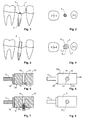
- the following is an embodiment of the invention described by an example. It is about to the restoration of a molar with a crown.
- Fig. 1 and 2 show a row of teeth with missing Molar 1, in its position a dental implant 2 was anchored in the jawbone.
- the implant head 3 of the dental implant 2 is in a known manner with a polygonal Profile and an internal thread provided, the one Form fixture and fix the restoration serve.
- the situation of the exposed implant head 3 is measured three-dimensionally.
- the three-dimensional position and position of the implant head analogous to dental technology using an auxiliary body, hereinafter referred to as "transfer abutment" 4, as shown in Figs. 3 and 4.
- the transfer abutment 4 fits exactly on the fixture of the implant head 3, and is screwed on this to the exact seat, so that it is in a predetermined position to the implant head 3 stands.
- the transfer abutment 4 extends this intraosseous dental implant 2 in its axial direction in the area of the clinical tooth crown. It owns prismatic shape with preferably hexagonal or octagonal Cross-section, depending on the geometry of the fixture.
- the occlusal surface 5 of the transfer abutment 4 represents the spatial form and location of the Implant head in the gingivo-cervical area with the distance, which is defined by the height of the transfer abutment 4 becomes. It also informs about the angular deviation the fixture of the implant against occlusal (occlusion) Level.
- the transfer abutment 4 has suitable for optical three-dimensional measuring technology Opaque surfaces and lies with the occlusal surface in the Focusing and measuring range of the measuring system. At the oral optical three-dimensional measurement with the Cerec-3D Mouth camera will be gingiva and adjacent teeth with an opaque Covered powder or spray.
- the determination of the crown shape is done, for example with the software of the CEREC system mentioned above, which the modifications characterizing the method contains.
- the recorded by the measuring system Situation presented on the screen and the user marks relevant points and lines.
- Starting point is the measured and stored shape, position and location of the implant head 3.
- the user identifies in one first step in the virtual model of the tooth or Jaw area the outer edge of the occlusal hexaoder octagonal surface 5 of the transfer abutment 4 with a line and additionally the mesio-distal row of teeth nearest mesial and distal corners 7 through point inputs.
- the straight connecting line of this Point 7 through the center marks the angular position the implant fixture with respect to the mesio-distal row of teeth.
- the system learns through these inputs the Angular deviation of the implant fixture against the mesio-distal Tooth axis and its mesio-distal and Oro-buccal spatial orientation.
- the mesio-distal row of teeth represents together with the occlusal plane the Main axis for the construction of the crown.
- the stored spatial data of the implant head with the help of the spatial identification by the transfer abutment in the three-dimensional data model of assigned to gingivo-cervical location.
- the second step is the cervical crown outline following the course of the gingival margin.
- the elevation data of the ground line will be from the elevation taken over the gingiva.
- the line is editable.
- Between the outer edge of the implant head 3 and the cervical crown outline become the subgingival Surface of the crown generated.
- the crown On the gingival edge the crown becomes a virtual crown of the true Tooth type adapted from a dental database, or it will a registry of the situation used before tooth loss.
- the emergence profile of the buccal, lingual and proximal Crown surfaces may be in the area of the cervical crown outline determined with a coronal exit angle become.
- the mesio-distal, proximal and occlusal Alignment and adjustment of the crown shape is done with the tools of the available crown software.
- For the Machine shaped loops of the implant crown become the Design data converted into grinding data.
- a blank is processed, as in Fig. 5 and 6 is shown.
- This has a blank block or block 10, for example, from a ceramic material or composite, and a Holder 11, for mounting in a computer controlled Machining tool is used.
- the holder 11 is provided with a first surface 12 of the block 10, e.g. by Glue. Blanks of this kind are e.g. from US 4,615,678 known.
- an implant connection part 14 is arranged. It deals this is an implant-specific precision part made of material with high breaking strength, which is a ensures precise fit of the crown on the implant head 3 and the fixed screw connection with this allowed.
- the implant connector 14 is fixed to the block 10 connected.
- the block 10 has a central channel 16 on, extending from the implant connector 14 across extends the block 10.
- the channel 16 passes through the Center of the block 10 and parallel to the first surface 12. He takes a fixing screw 12 and allows access to the screw 12 by means of a screwdriver, so that the connection part 14 together with formgeschliffener crown can be screwed to the implant.
- the implant connector 14 is plane-parallel with its peripheral plane arranged to the second surface 13 of the block 10.
- the Arrangement of the Fixturgeometrie of the connection part 14 is located towards the geometry of the block 10 in one standardized arrangement.
- the implant connector 14 is e.g. made of metal or a break-proof ceramic, since it is high To absorb forces. He is partially sunk in block 10 and may, as shown, partially over the surface 13 stand out. If the implant connector protruding over the surface 13, must when sanding less material is removed from the crown.
- the implant connector 14 has a axial opening 17 for the shaft of the fastening screw 12 and a polygonal serving as a fixture Seat 18 adapted to the shape of the implant head 3 is.
- the identification of the position of the implant connection part 14 in block 10 important. This happens with the help of a reference part 20 in the form of a Material body, as shown in FIGS. 7 and 8.
- the reference part 20 is connected to the implant connection part 14 connected and from the machining tool directly to Identification of his position approached.
- the form and Size of the reference part 20 is stored in the machine.
- the identification is e.g. through touch-ups on opposite axial sides and up the endface or by optical scanning. If the implant connector 14 far enough over the second Surface 13 of the block 10 projects, its position possibly without a special reference part be measured directly. It is also possible to change the position of the channel 16 to measure. Is the position of the implant connector relative to the holder 11 exactly known Under certain circumstances, a measurement of the position is sufficient of the owner.
- the crown construction to be ground from the block 10 is according to their connection to the implant connector 14 oriented in block 10.
- For tilting of the implant head 3 with respect to the occlusal plane becomes the entire crown construction according to these in the blank block aligned. Below 15-20 degrees They can, by choosing the shooting angle, the orientation of the virtual rack model and also be compensated by the tolerance of the grinding arrangement, especially since the necessary in conventional crowns Internal grinding to accommodate the abutment is eliminated. at Tilting wanders the opening of the access channel for the screw fastening of the crown from the center of the Chewing surface.
- a crown 21 form-cut After determining the position of the implant connection part 14 is in a conventional manner a crown 21 form-cut.
- This can, as in Fig. 9 represented, then attached to the implant head 3 be by the fastening screw 22 in the channel 16 inserted and screwed into the implant 2. thereupon becomes the channel 16, e.g. a diameter of 2.5 mm owns, closed.
- This can be plastic tooth restoration material or a plug 23 is used become.
- the latter is preferably the same Material like block 10 is in its diameter Channel 16 adapted and is glued in the channel 16 and on ground off the occlusal surface. Will be a plug 23 used, this is enough in his full thickness preferably not quite up to the fastening screw 22, so that the fixing screw if necessary be re-exposed later without damage can.
- a spacer element 24 is arranged, that of another material (e.g., silicone) than the closure pin 23 is made and / or a smaller one Cross-sectional area than the closure pin 23 has. If the plug is drilled out, the spacer element can 24 without mechanical damage to the Screw are removed.
- another material e.g., silicone
- a preferred material for the block 10 is Glass ceramic, in particular a lithium silicate ceramic or any other material that comes after sanding elevated temperature can be tempered and thereby Strength gains. Other post-treatment methods for Increasing the strength after the form grinding can also be used.
- block 10 may be also made of composite, feldspar ceramic or leucite glass ceramic be.
- the implant connector can 14 consist of the same material as the block 10 and is preferably formed integrally therefrom.
- the implant connection part 14 is preferred however, manufactured separately, so he without much effort can be produced in the required accuracy. Especially when the implant connector 14 made of metal is, it can be precisely manufactured in a simple manner and still has the necessary breaking strength. To its production is the implant connector 14th permanently anchored in block 10.
- the implant connection part 14 of FIG. 5 - 8 shown blank 10 forms only a negligible Part of the gingiva-sided surface of the finished Crown.
- implant connecting part 14 but also a bigger gingiva workede Form base plate of the crown. He owns this a pre-polished or pre-glazed, convexly curved outer surface 26, preferably over the second surface 13 protrudes so that less material is ground must be, and that is not processed.
- the smooth pre-polished or glazed outer surface 26 the Advantage that it is tissue-friendly.
- FIG. 10 becomes gingiva-forming before inserting the crown Abutment placed on the implant, which corresponds to a shape the outer surface 26 has and during the healing process imprints this form of gingiva. thereupon The gingiva-forming abutment is removed and the crown is removed is used. Here, the gingiva of the outer surface nestles 26 good.
- the invention relates to the shape data for the tooth crown to be created by measurement in the patient's mouth determined.
- the invention is also suitable for Application in the dental laboratory. For this, e.g. first a conventional impression of the to be restored Tooth row of the patient taken and therefrom by molding a model 30 are created, as shown in FIG. 11 is shown. This is in a conventional manner Transfer abutment recorded in the impression and thus a corresponding implant 2 'in the model 30 is positioned.
- the created model 30 essentially gives the situation of Fig. 1 and 2 again.
- a growth abutment 29 which has a body 31 e.g. made of wax or another, well-connected with wax Material has, and - similar to the blank - an implant connector 32.
- the latter fits on the Implant 2 'and can be fixed with a screw 22 in this become.
- a channel 33 is provided for insertion and operation of the screw 22 in the body 31 for insertion and operation of the screw 22 in the body 31, a channel 33 is provided.
- the dental technician then attaches the growth abutment 29 on the implant 2 'of the model 30 and grows in a conventional manner on a tooth crown 34, which has the shape of the tooth to be restored. thereupon is the tooth crown 34 by loosening the screw 22 from the Model 30 is removed and placed in an optical or mechanical Scanning device used where their shape is recorded. In this case, in particular, the position of the channel 33rd and the implant fitting 32.
- the won Data can, as in the method described above, be used for the grinding of the block 10.
- the blanks according to FIGS. 5 - 8 and 10 are provided with a holder 11, with which they in one Machining tool can be attached.
- editing tools can the blocks 10 without holder 11th Tobe offered.
- the attachment over one or more surface areas of the Blocks happens, which are transverse to the surface 13, so that the area of the second surface around the implant connection part 14 as well as the corresponding area on the remain free on the opposite side.
- the block may be on the surfaces 12, 12a, 12b and 12c (Fig. 6) in mounting jaws of the machining tool be clamped. Since the surface 13 in the area of Implant connector 14 and the corresponding area the opposite side can stay clear Restaurat be created in the usual way.
- the practitioner can be offered a parts set, which contains one or more blanks.
- a parts set which contains one or more blanks.
- the set of parts can also use screws and a matching screwdriver contain.
Abstract
Description
Die Erfindung betrifft einen Rohling und ein Verfahren zur Herstellung einer Zahnrestauration sowie einen Teilesatz mit einem derartigen Rohling gemäss Oberbegriff der unabhängigen Ansprüche. Insbesondere beschreibt das Verfahren die Herstellung von Zahnkronen mittels CAD/CAM, CAM oder Kopierschleifvorrichtungen als prothetische Suprastruktur für Zahnimplantate unter Verwendung von Rohlingsblöcken aus restaurativem Material, die mit einem integrierten Implantat-Anschlussteil versehen sind, welcher eine implantat-typische Fixtur aufweist und den direkten Anschluss einer aus dem Block hergestellten Krone an den Kopf des Zahnimplantats erlaubt.The invention relates to a blank and a Process for producing a dental restoration as well a parts set with such a blank according to the preamble the independent claims. In particular, describes the procedure the production of dental crowns using CAD / CAM, CAM or copy grinders as prosthetic superstructure for dental implants using of blank blocks of restorative material, which are provided with an integrated implant connector are, which has an implant-typical fixture and the direct connection of one made from the block Crown allowed to the head of the dental implant.
Die Herstellung von Zahnkronen zur Versorgung von Implantaten per Computerdesign erfolgt üblicherweise über den Zwischenschritt der Herstellung von prothetischen Aufbauten ("Implantat-Abutment") in Form eines Zahnstumpfes (Hegenbarth 1999, Implantologie 3: 297-307), dies in Analogie zur Herstellung von Kronen bei noch vorhandenen natürlichen Zähnen. Bei diesen präpariert der Zahnarzt die noch vorhandene Zahnhartsubstanz zu einer pfeilerartigen, im Wesentlichen der Zahnachse und einer Einschubachse folgenden, zur Kaufläche bzw. Okklusionsebene hin zirkulär konvergenten Stumpfform, die zur Aufnahme der künstlichen Vollkrone geeignet ist. Bei Zahnimplantaten können vorkommende Abweichungen der Achsrichtung gegenüber der Okklusionsebene von bis zu 20 Winkelgraden mittels Ausrichtung der Einschubachse des Implantat-Abutments ausgeglichen werden. Für die Herstellung von Implantat-Abutments und -Kronen ist die genaue Erfassung der Position des Implantats selbst und auch der den Implantatkopf umgebenden Gingiva von besonderer Wichtigkeit. Beide bestimmen die anatomisch korrekte Gestaltung des Implantat-Abutments im subgingivalen Bereich. Der Umriss der Krone im gingivalen Bereich soll dem der natürlichen Zahnwurzel gleichen. Der Übergang zur Krone (Emergenzprofil) orientiert sich ebenfalls am natürlichen Zahn, um eine natürliche Gingivakontur zu erzielen. Mit Hilfe eines "Guide-Pins" und eines mit einer Skala versehenen "T-Bars" wird die Implantatposition dreidimensional in den Rechner des Computers übertragen. Während der auf das Implantat aufgeschraubte "Guide-Pin" die oro-bukkale und mesio-distale Ausrichtung des Implantates darstellt, gibt der "T-Bar" die Höhenposition des Implantatkopfes im gingivalen Bereich des Modells wider. Damit ist die Achsenneigung und die Höhenposition des Implantatkopfes für das individuelle Design des "Abutments" bekannt (Hegenbarth 1999, Implantologie 3: 297-307). Dieses wird aus Titan oder Hochleistungskeramik gefertigt. Die dazu passende Krone wird mit zahntechnischen und computertechnischen Schritten hergestellt.The manufacture of dental crowns for restoration implants are usually done by computer design about the intermediate step of the production of prosthetic Abutments ("implant abutment") in the form of a Tooth stump (Hegenbarth 1999, Implantology 3: 297-307), this in analogy to the production of crowns in still existing natural teeth. In these prepared the Dentist the remaining tooth hard tissue to a pillar-like, essentially the tooth axis and one Insertion axis following, to the occlusal or occlusal plane towards circular convergent stump shape, which is receptive the artificial full crown is suitable. For dental implants can occur deviations of the axial direction opposite the occlusal plane of up to 20 angular degrees by aligning the insertion axis of the implant abutment be compensated. For the production of implant abutments and crowns is accurate detection the position of the implant itself and also the Implant head surrounding gingiva of particular importance. Both determine the anatomically correct design of the implant abutment in the subgingival region. The outline The crown in the gingival area should be that of the natural one Tooth root same. The transition to the crown (emergence profile) is also based on the natural Tooth to achieve a natural gingival contour. With Help a "guide pin" and a scale provided "T-Bars", the implant position becomes three-dimensional transferred to the computer of the computer. While on the implant screwed on "guide pin" the oro-buccal and mesio-distal orientation of the implant, gives the "T-bar" the height position of the implant head in gingival area of the model. This is the axis inclination and the height position of the implant head for the individual design of the "abutment" known (Hegenbarth 1999, Implantology 3: 297-307). This is going out Titanium or high-performance ceramics made. The matching one Krone is using dental and computer technology Steps made.
Das Cerec CAD/CAM System (Sirona Dental Systems, Bensheim, Deutschland), eignet sich zur Versorgung von Zähnen mit Vollkronen aus Keramik (Mörmann et al., ISBN 3-9521752-1-8). Bei der Kronenfertigung mit Cerec werden bisher die Implantate mit Hilfe von Standardabutments aus Titan oder Keramik aufgebaut. Ungünstige Achsneigungen von Zahnimplantaten können mit gewinkelten Standardabutments ausgeglichen werden. Alternativ können die Konvergenzwinkel und der gingivale Rand von Standardabutments aus Hochleistungskeramik (wie z.B. ZiReal von Implant Innovations Inc.) durch manuelles Beschleifen angepasst werden. Abutments mit geeigneter Stumpfrichtung und genügendem Konvergenzwinkel können sowohl mit der Cerec-3D Mundkamera als auch nach Abformung und Modellherstellung mit der Laserabtastung im Cerec inLabgerät aufgenommen werden. Die Konstruktion und Fertigung der Krone erfolgt dann auf dem Stumpf mit bekannten Schritten wie beim vitalen Zahn (Masek 2003, Int J Comp Dent 6: 75-82). Die Kronen werden in der Cerec 3-Schleifeinheit aus Rohlingsblöcken von beschleifbarem Restaurationsmaterial (Keramik) formgeschliffen (Mörmann & Bindl 2000, Quintessence Int 31:699-712; Mörmann & Bindl 2002, Dent Clin N Am 46: 405-426). In ähnlihcer Weise erfolgt dies in anderen bekannten System zur Herstellung von dentalen Restaurationen, wie z.B. der handgesteuerten Celay-Kopiertechnik (Crispin 1996, Quintessence, Chicago, Seite 68), der DCM/Cercon Technik (Filser et al., 2001, Int. J. Comp. Dent. 4: 89 - 106), der LAVA-Technik (Sutter et al. 2001, Int. J. Comp. Dent. 4: 195 - 206), der DCS-Technik (Besimo et al. 2001, Int. J. Comp. Dent. 4: 243 - 262), der GN-1 Technik (Hikita et al. 2002, Int. J. Comp. Dent. 5: 11 - 23). In jedem Fall verlangt die CAD/CAM Fertigung von Implantatkronen entsprechend der konventionellen Verfahrensweise die Herstellung eines achsengerechten Abutments, mit dem nachfolgenden Einsetzen und Befestigen der Krone.The Cerec CAD / CAM System (Sirona Dental Systems, Bensheim, Germany), is suitable for care of teeth with full ceramic crowns (Mörmann et al., ISBN 3-9521752-1-8). For crown production with Cerec So far, the implants are using standard abutments made of titanium or ceramic. unfavorable Achsneigungen of dental implants can be with angled Standard abutments are balanced. Alternatively you can the convergence angles and the gingival margin of standard abutments high performance ceramics (such as ZiReal from Implant Innovations Inc.) adapted by manual grinding become. Abutments with suitable butting direction and enough convergence angle can be used with both the Cerec 3D Mouth camera as well as after impression and model production recorded with the laser scanning in the Cerec inLabgerät become. The design and manufacture of the crown then done on the stump with known steps such as vital tooth (Masek 2003, Int J Comp Dent 6: 75-82). The crowns are made of blank blocks in the Cerec 3 grinding unit of grindable restoration material (Ceramic) form-ground (Mörmann & Bindl 2000, Quintessence Int 31: 699-712; Mörmann & Bindl 2002, Dent Clin N 46: 405-426). In a similar way this is done in others known system for the production of dental restorations, such as. the hand-controlled Celay copying technology (Crispin 1996, Quintessence, Chicago, page 68), the DCM / Cercon technique (Filser et al., 2001, Int. Comp. Dent. 4: 89-106), the LAVA technique (Sutter et al. 2001, Int. J. Comp. Dent. 4: 195-206), the DCS technique (Besimo et al 2001, Int J. Comp. Dent. 4: 243-262), the GN-1 technique (Hikita et al., 2002, Int. J. Comp. Dent. 5: 11-23). In any case, the CAD / CAM production requires of implant crowns according to the conventional procedure the production of an axis-compatible abutment, with the subsequent insertion and securing the Crown.
In dem Bemühen, die Kronenversorgung von Zahnimplantaten zu vereinfachen, wurde vorgeschlagen, Implantatfixturen in Materialblöcken auszuformen und Abutments sowie Kronen mit Hilfe der CAD/CAM-Technologie (Abutments) herzustellen (De Luca 1999, EP 1 023 876 A2). Diese Lösung ist jedoch nicht ohne apparative Modifikationen bei herkömmlichen Bearbeitungssystemen z.B. der Cerec-Klasse einsetzbar.In an effort to secure the crown of dental implants To simplify, implant fixtures have been proposed in material blocks and abutments as well as crowns using the CAD / CAM technology (Abutments) (De Luca 1999, EP 1 023 876 A2). However, this solution is not without apparative modifications in conventional processing systems e.g. of the Cerec class can be used.
Die Versorgung von Zahnimplantaten mit Abutment-Vollkronen stellt eine anspruchsvolle und zeitraubende Arbeit dar, die mit der vorliegenden Erfindung vereinfacht und verkürzt werden soll.The supply of dental implants with abutment full crowns represents a demanding and time-consuming Work that simplifies with the present invention and should be shortened.
Diese Aufgabe wird von der in den unabhängigen Ansprüchen definierten Erfindung gelöst.This task is carried out by the independent Claims defined invention solved.
Erfindungsgemäss wird der Block also an mindestens einer ersten Oberfläche an einem Halter bzw. der Bearbeitungsvorrichtung befestigt. An einer zweiten Oberfläche des Blocks, die ungefähr senkrecht oder zumindest quer zur ersten Oberfläche bzw. zu den ersten Oberflächen steht, ist ein Implantat-Anschlussteil angeordnet, in welchem eine Implantat-Fixtur zur Befestigung des ausgebarbeiteten Kronenwerkstücks an einem Implantatkopf ausgeformt ist. Dabei sind die erste(n) und die zweite Oberfläche im wesentlichen rechtwinklig oder quer zueinander angeordnet. Somit kann die zweite Oberfläche (und die der zweiten Oberfläche gegenüberliegende Fläche) zumindest in einem mittleren Bereich für die Bearbeitungsinstrumente frei zugänglich bleiben (eine geringe Umfassung der Randbereiche der zweiten Fläche durch den Halter stört dabei nicht). Dies erlaubt es, die okklusale-gingivale Achse der herzustellenden Krone parallel zur ersten Oberfläche bzw. senkrecht zur Achse des Halters zu orientieren, wie dies auch bei der Bearbeitung konventioneller Rohlingsblöcke der Fall ist. Somit sind zur Bearbeitung der neuen Rohlinge nur minimale Änderungen der Verfahrensschritte und der Bearbeitungsvorrichtung erforderlich.According to the invention, the block is thus at least a first surface on a holder or the Attached processing device. On a second surface of the block, which is approximately vertical or at least transverse to the first surface or to the first surfaces is located, an implant connector is arranged in which an implant fixture for fixing the developed Crown workpiece formed on an implant head is. Here are the first and the second surface substantially perpendicular or transverse to each other arranged. Thus, the second surface (and that of the second surface opposite surface) at least in a middle area for the editing tools remain freely accessible (a small enclosure of the edge areas the second surface through the holder interferes with it Not). This allows the occlusal-gingival axis the crown to be produced parallel to the first surface or perpendicular to the axis of the holder to orient how this also when processing conventional blank blocks the case is. Thus are to process the new Blanks only minimal changes in the process steps and the processing device required.
Die Implantat-Fixtur erlaubt es, Vollkronen direkt, unter Verzicht auf die Herstellung und Montage eines Abutments, auf den Kopf des inkorporierten Zahnimplantates zu konstruieren, in konventionellen automatischen oder handgesteuerten Bearbeitungsgeräten bzw. dentalen Kopierbearbeitungsgeräten formzuschleifen und im Mund lagegerecht direkt mit der Fixtur des Zahnimplantates zu befestigen.The implant fixture allows full crowns directly, waiving the manufacturing and assembly of an abutment, on the head of the incorporated dental implant to construct, in conventional automatic or hand-controlled processing devices or dental Sanding copy processing equipment and in Mouth correctly aligned directly with the fixture of the dental implant to fix.
Die Daten zum Formschleifen der Krone können beispielsweise durch optische Messung auf dem freiliegenden Kopf des Zahnimplantats direkt im Mund des Patienten (z.B. mit der CEREC-Kamera) gewonnenen werden oder durch Laserabtastung eines zahntechnisch hergestellten Modells dieser Situation (z.B. in den CEREC inLab, DCS oder GN-1-Verfahren). Im zweiten Fall kann mit Hilfe eines Übertragungsabutments ein stellvertretendes Implantat situationsgenau plaziert werden. Auf dieses wird eine stellvertretende Fixtur befestigt und die Krone situationsgerecht aufgewachst. Die aufgewachste Krone wird dann mit Hilfe der bekannten Lasertriangulation (DCM-Cercon, Lava, DCS, GN-1, CEREC inLab) samt der Fixtur räumlich abgetastet. Die Fixtur dient dabei als Referenz für die Orientierung des Datensatzes im Rohlingsblock. Sodann wird ein Rohlingsblock mit Implantat-Fixtur entsprechend diesen Daten formgeschliffen.The data for shaping the crown can for example, by optical measurement on the exposed Head of the dental implant directly in the patient's mouth (e.g., with the CEREC camera) or through Laser scanning of a dental model this situation (e.g., in the CEREC in Lab, DCS, or GN-1 method). In the second case, using a transfer abutment a representative implant accurate to the situation be placed. This will be a deputy Fixture attached and the crown appropriate to the situation waxed. The waxed crown will then be using known laser triangulation (DCM-Cercon, Lava, DCS, GN-1, CEREC inLab) spatially scanned along with the fixture. The fixture serves as a reference for orientation of the record in the blank block. Then, a blank block with implant fixture according to this data form ground.
Vorzugsweise besteht der Implantat-Anschlussteil aus einem anderen Material als der Block, z.B. aus einem Material mit höherer Bruchfestigkeit, so dass Block und Anschlussteil je an die unterschiedlichen Anforderungen, denen sie gerecht werden müssen, angepasst werden können.Preferably, the implant connection part consists of a material other than the block, e.g. out a material with higher breaking strength, so block and connecting part depending on the different requirements, which they need to be accommodated can.
Denkbar ist jedoch auch, dass der Implantat-Anschlussteil und der Block aus dem gleichen Material bestehen und insbesondere einstückig ausgestaltet sind. In diesem Fall sollte ein Material mit hoher Bruchfestigkeit verwendet werden. Besonders vorteilhaft ist in diesem Zusammenhang Glaskeramik, insbesondere Lithiumsilikat-Keramik, oder ein anderes Material, dem nach der mechanischen Bearbeitung im CEREC-Gerät durch Nachbehandlung, insbesondere Tempern, d.h. Behandeln bei erhöhter Temperatur, eine höhere Festigkeit verliehen werden kann.It is also conceivable that the implant connector and the block is made of the same material and in particular are designed in one piece. In This case should be a material with high breaking strength be used. It is particularly advantageous in this context Glass ceramic, in particular lithium silicate ceramic, or another material, according to the mechanical Processing in the CEREC device by aftertreatment, in particular annealing, i. Treat at elevated temperature, a higher strength can be awarded.
Die Erfindung betrifft auch einen Teilesatz zur Herstellung einer Zahnrestauration, insbesondere einer Zahnkrone, mit mindestens einem Rohling dieser Art.The invention also relates to a parts set for producing a dental restoration, in particular a Tooth crown, with at least one blank of this type.
Vorzugsweise wird die Position des Implantat-Anschlussteils ausgemessen und der Rohling so bearbeitet, dass die vorgegebene Restaurationsoberfläche relativ zur Position des Implantat-Anschlussteils gebildet wird. Durch diese Schritte wird sichergestellt, dass die Restaurationsoberfläche die korrekte Position zum Implantat-Anschlussteil und somit zum Implantat besitzt.Preferably, the position of the implant connecting part measured and the blank edited so that the given restoration surface is relative to Position of the implant connection part is formed. These steps will ensure that the restoration surface the correct position to the implant connection part and thus has the implant.
Weitere bevorzugte Ausführungen und Vorteile
der Erfindung ergeben sich aus den abhängigen Ansprüchen
sowie aus der nun folgenden Beschreibung anhand der Figuren.
Dabei zeigen:
Im Folgenden wird eine Ausführung der Erfindung an einem Beispiel beschrieben. Dabei handelt es sich um die Restauration eines Backenzahns mit einer Krone.The following is an embodiment of the invention described by an example. It is about to the restoration of a molar with a crown.
Fig. 1 und 2 zeigen eine Zahnreihe mit fehlendem
Backenzahn 1, an dessen Position ein Zahnimplantat
2 im Kieferknochen verankert wurde. Der Implantatkopf 3
des Zahnimplantats 2 ist in bekannter Weise mit einem polygonalen
Profil und einem Innengewinde versehen, die eine
Fixtur bilden und zur Befestigung der Restauration
dienen.Fig. 1 and 2 show a row of teeth with missing
Molar 1, in its position a
Die Situation des freiliegenden Implantatkopfes
3 wird dreidimensional vermessen. Hierzu wird die
dreidimensionale Lage und Position des Implantatkopfes
analog zur Zahntechnik unter Verwendung eines Hilfskörpers,
im folgenden "Übertragungsabutment" 4 genannt, erfasst,
wie es in Fig. 3 und 4 dargestellt ist. Das Übertragungsabutment
4 passt exakt auf die Fixtur des Implantatkopfes
3, und wird auf diesen zum exakten Sitz aufgeschraubt,
so dass er in vorgegebener Lage zum Implantatkopf
3 steht. Das Übertragungsabutment 4 verlängert das
intraossär liegende Zahnimplantat 2 in seiner Achsrichtung
in den Bereich der klinischen Zahnkrone. Es besitzt
prismatische Form mit vorzugsweise hexagonalem oder oktagonalem
Querschnitt, je nach Fixturgeometrie. Seine Seitenflächen
enden okklusal in einer Fläche 5, welche durch
eine Bohrung 6 für die zentrale Befestigungsschraube unterbrochen
wird. Die okklusale Fläche 5 des Übertragungsabutments
4 repräsentiert die räumliche Form und Lage des
Implantatkopfes im gingivo-zervikalen Bereich mit dem Abstand,
der durch die Höhe des Übertragungsabutments 4 definiert
wird. Sie informiert auch über die Winkelabweichung
der Fixtur des Implantats gegenüber der Kauflächen-(Okklusions)
Ebene. Das Übertragungsabutment 4 besitzt
für die optisch-dreidimensionale Messtechnik geeignete
opake Oberflächen und liegt mit der okklusalen Fläche im
Fokus- und Messbereich des Messsystems. Bei der oralen
optisch-dreidimensionalen Vermessung mit der Cerec-3D
Mundkamera werden Gingiva und Nachbarzähne mit einem opaken
Puder bzw. Spray eingedeckt.The situation of the exposed
Nebst der Messung der Position und Lage des
Implantats 2 werden auch die Grösse und Form der Zahnlükke
sowie die Lagen der Nachbarzähne in bekannter Weise
ausgemessen.In addition to measuring the position and location of the
Die Ermittlung der Kronenform erfolgt beispielsweise
mit der Software des oben erwähnten CEREC-Systems,
welche die das Verfahren kennzeichnenden Modifikationen
enthält. Dabei wird die vom Messsystem aufgenommene
Situation am Bildschirm dargestellt und der Benutzer
markiert relevante Punkte und Linien. Ausgangspunkt ist
die gemessene und abgespeicherte Form, Position und Lage
des Implantatkopfes 3. Der Benutzer identifiziert in einem
ersten Schritt im virtuellen Modell des Zahn- bzw.
Kieferbereichs den äusseren Rand der okklusalen hexaoder
oktagonalen Fläche 5 des Übertragungsabutments 4 mit
einer Linie und zusätzlich die der mesio-distalen Zahnreihenachse
nächstliegenden mesialen und distalen Ecken 7
durch Punkteingaben. Die gerade Verbindungslinie dieser
Punkte 7 durch den Mittelpunkt markiert die Winkellage
der Implantatfixtur bezüglich der mesio-distalen Zahnreihenachse.
Das System erfährt durch diese Eingaben die
Winkelabweichung der Implantatfixtur gegenüber der mesio-distalen
Zahnreihenachse sowie seine mesio-distale und
oro-bukkale Raumorientierung. Die mesio-distale Zahnreihenachse
stellt zusammen mit der Okklusionsebene die
Hauptachse für die Konstruktion der Krone dar. Die gespeicherten
räumlichen Daten des Implantatkopfes werden
mit Hilfe der räumlichen Identifikation durch das Übertragungsabutment
im dreidimensionalen Datenmodell der
gingivo-zervikalen Lage zugeordnet.The determination of the crown shape is done, for example
with the software of the CEREC system mentioned above,
which the modifications characterizing the method
contains. In this case, the recorded by the measuring system
Situation presented on the screen and the user
marks relevant points and lines. Starting point is
the measured and stored shape, position and location
of the
Zum Ermitteln der Kronenform wird im ersten
Schritt die äussere Zirkumferenz des Implantatkopfes 3
mit der Eingabe einer zirkulär geschlossenen Bodenlinie
markiert. Im zweiten Schritt wird die zervikale Kronenumrisslinie
dem Verlauf des Gingivarandes folgend eingegeben.
Die Höhendaten der Bodenlinie werden aus dem Höhenverlauf
der Gingiva übernommen. Die Linie ist editierbar.
Zwischen dem äusseren Rand des Implantatkopfes 3 und der
zervikalen Kronenumrisslinie werden die subgingivalen
Oberflächen der Krone generiert. Auf den gingivalen Rand
der Krone wird eine virtuelle Krone des zutreffenden
Zahntyps aus einer Zahndatenbank angepasst, oder es wird
ein Registrat der Situation vor Zahnverlust verwendet.
Das Emergenzprofil der bukkalen, lingualen und approximalen
Kronenoberflächen kann im Bereich der zervikalen Kronenumrisslinie
mit einem koronalen Austrittswinkel bestimmt
werden. Die mesio-distale, approximale und okklusale
Ausrichtung und Anpassung der Kronenform erfolgt mit
den Werkzeugen der verfügbaren Kronensoftware. Für das
maschinelle Formschleifen der Implantatkrone werden die
Konstruktionsdaten in Schleifdaten umgewandelt.To determine the crown shape is in the first
Step the outer circumference of the
Sodann wird ein Rohling bearbeitet, wie er in
Fig. 5 und 6 dargestellt ist. Dieser besitzt einen Rohlingsblock
bzw. Block 10, der beispielsweise aus einem
keramischen Material oder Komposit besteht, und einen
Halter 11, der zur Halterung in einem computergesteuerten
Bearbeitungswerkzeug dient. Der Halter 11 ist mit einer
ersten Oberfläche 12 des Blocks 10 verbunden, z.B. durch
Kleben. Rohlinge dieser Art sind z.B. aus US 4 615 678
bekannt.Then a blank is processed, as in
Fig. 5 and 6 is shown. This has a blank block
or block 10, for example, from a
ceramic material or composite, and a
An einer zweiten Oberfläche 13, die rechtwinklig
zur ersten Oberfläche 12 des Blocks 10 steht, ist
ein Implantat-Anschlussteil 14 angeordnet. Es handelt
sich dabei um ein implantatspezifisches Präzisionsteil
aus Material mit hoher Bruchfestigkeit, welches einen
präzisen Sitz der Krone auf dem Implantatkopf 3 gewährleistet
und die feste Verschraubung mit diesem erlaubt.
Das Implantat-Anschlussteil 14 ist fest mit dem Block 10
verbunden. Der Block 10 weist einen zentralen Kanal 16
auf, der sich vom Implantat-Anschlussteil 14 quer durch
den Block 10 erstreckt. Der Kanal 16 verläuft durch die
Mitte des Blocks 10 und parallel zur ersten Oberfläche
12. Er nimmt eine Befestigungsschraube 12 auf und ermöglicht
den Zugang zur Schraube 12 mittels Schraubenzieher,
so dass der Anschlussteil 14 samt formgeschliffener Krone
mit dem Implantat verschraubt werden kann. Der Implantat-Anschlussteil
14 ist mit seiner Umfangsebene planparallel
zur zweiten Oberfläche 13 des Blocks 10 angeordnet. Die
Anordnung der Fixturgeometrie des Anschlussteiles 14 befindet
sich gegenüber der Geometrie des Blocks 10 in einer
standardisierten Anordnung.At a
Der Implantat-Anschlussteil 14 besteht z.B.
aus Metall oder einer bruchfesten Keramik, da er hohe
Kräfte aufnehmen muss. Er ist teilweise im Block 10 versenkt
und kann, wie dargestellt, teilweise über die Oberfläche
13 herausstehen. Wenn der Implantat-Anschlussteil
über die Oberfläche 13 heraussteht, muss beim Formschleifen
der Krone weniger Material abgetragen werden.The
Der Implantat-Anschlussteil 14 besitzt eine
achsiale Öffnung 17 für den Schaft der Befestigungsschraube
12 und einen als Fixtur dienenden polygonalen
Sitz 18, welcher der Form des Implantatkopfs 3 angepasst
ist.The
Für das Formschleifen der Krone im Bearbeitungswerkzeug
ist die Identifikation der Lage des Implantat-Anschlussteiles
14 im Block 10 wichtig. Dies geschieht
mit Hilfe eines Referenzteils 20 in Form eines
Materialkörpers, wie er in Fig. 7 und 8 dargestellt ist.
Der Referenzteil 20 wird mit dem Implantat-Anschlussteil
14 verbunden und vom Bearbeitungswerkzeug direkt zur
Identifikation seiner Position angefahren. Die Form und
Grösse des Referenzteils 20 ist in der Maschine gespeichert.
Die Identifikation geschieht z.B. durch Touchierungen
auf gegenüberliegenden achsialen Seiten und auf
der Endfläche oder durch optische Abtastung. Wenn der Implantat-Anschlussteil
14 ausreichend weit über die zweite
Fläche 13 des Blocks 10 vorsteht, kann dessen Position
unter Umständen auch ohne einen speziellen Referenzteil
direkt ausgemessen werden. Es ist auch möglich, die Position
des Kanals 16 auszumessen. Ist die Position des Implantat-Anschlussteils
relativ zum Halter 11 genau bekannt,
so genügt unter Umständen eine Ausmessung der Position
des Halters.For the shaping of the crown in the machining tool
is the identification of the position of the
Die aus dem Block 10 zu schleifende Kronenkonstruktion
wird gemäss ihrer Anbindung an das Implantat-Anschlussteil
14 im Block 10 orientiert. Bei Kippungen
des Implantatkopfes 3 gegenüber der Okklusionsebene
wird die gesamte Kronenkonstruktion gemäss diesen im Rohlingsblock
ausgerichtet. Unterhalb von 15-20 Winkelgraden
können sie durch die Wahl des Aufnahme-Winkels, die Orientierung
des virtuellen Zahnreihenmodelles und auch
durch die Toleranz der Schleifanordnung kompensiert werden,
insbesondere da der bei konventionellen Kronen nötige
Innenschliff zur Aufnahme des Abutments entfällt. Bei
Verkippungen wandert die Öffnung des Zugangskanals für
die Schraubenbefestigung der Krone aus dem Zentrum der
Kaufläche. The crown construction to be ground from the
Nach der Bestimmung der Position des Implantat-Anschlussteiles
14 wird in an sich bekannter Weise
eine Krone 21 formgeschliffen. Diese kann, wie in Fig. 9
dargestellt, sodann auf dem Implantatkopf 3 befestigt
werden, indem die Befestigungsschraube 22 in den Kanal 16
eingeführt und im Implantat 2 verschraubt wird. Sodann
wird der Kanal 16, der z.B. einen Durchmesser von 2.5 mm
besitzt, verschlossen. Hierzu kann plastisches Zahnrestaurationsmaterial
oder ein Verschlusszapfen 23 verwendet
werden. Letzterer besteht vorzugsweise aus dem gleichen
Material wie Block 10, ist in seinem Durchmesser dem
Kanal 16 angepasst und wird im Kanal 16 eingeklebt und an
der okklusalen Oberfläche abgeschliffen. Wird ein Verschlusszapfen
23 verwendet, so reicht dieser in seiner
vollen Dicke vorzugsweise nicht ganz bis zur Befestigungsschraube
22, damit die Befestigungsschraube nötigenfalls
später ohne Beschädigung wieder freigelegt werden
kann. In einer bevorzugten Ausführung ist an der Spitze
des Verschlusszapfens 23 ein Abstandselement 24 angeordnet,
das aus einem anderen Material (z.B. Silikon) als
der Verschlusszapfen 23 besteht und/oder eine kleinere
Querschnittsfläche als der Verschlusszapfen 23 aufweist.
Wird der Verschlusszapfen herausgebohrt, so kann das Abstandselement
24 ohne mechanische Beschädigung der
Schraube herausgelöst werden.After determining the position of the
Ein bevorzugtes Material für den Block 10 ist
Glaskeramik, insbesondere eine Lithiumsilikat-Keramik
oder ein anderes Material, das nach dem Formschleifen bei
erhöhter Temperatur getempert werden kann und dabei an
Festigkeit gewinnt. Andere Nachbehandlungsmethoden zur
Erhöhung der Festigkeit nach dem Formschleifen können
auch eingesetzt werden. Block 10 kann beispielsweise aber
auch aus Komposit, Feldspatkeramik oder Leuzitglaskeramik
sein.A preferred material for the
Bei Verwendung eines ausreichend festen Materials
für den Block 10, kann der Implantat-Anschlussteil
14 aus dem gleichen Material wie der Block 10 bestehen
und ist vorzugsweise einstückig aus diesem ausgeformt.When using a sufficiently strong material
for the
Bevorzugt wird der Implantat-Anschlussteil 14
jedoch separat gefertigt, so dass er ohne grossen Aufwand
in der nötigen Genauigkeit hergestellt werden kann. Insbesondere
wenn der Implantat-Anschlussteil 14 aus Metall
ist, kann er in einfacher Weise präzis gefertigt werden
und weist dennoch die nötige Bruchfestigkeit auf. Nach
seiner Herstellung wird der Implantat-Anschlussteil 14
permanent im Block 10 verankert.The
Der Implantat-Anschlussteil 14 des in Fig. 5
- 8 dargestellten Rohlings 10 bildet nur einen unwesentlichen
Teil der gingiva-seitigen Oberfläche der fertigen
Krone. Wie in Fig. 10 dargestellt, kann Implantat-Anschlussteil
14 jedoch auch eine grössere gingivaseitige
Basisplatte der Krone bilden. Hierzu besitzt er
eine vorpolierte bzw. vorglasierte, konvex gekrümmte Aussenfläche
26, die vorzugsweise über die zweite Oberfläche
13 vorsteht, so dass weniger Material formgeschliffen
werden muss, und die nicht bearbeitet wird. Zudem hat die
glatte vorpolierte bzw. glasierte Aussenfläche 26 den
Vorteil, dass sie gewebefreundlich ist.The
Bei der Anwendung der Ausführung nach Fig. 10
wird vor dem Einsetzen der Krone ein Gingiva-formendes
Abutment auf das Implantat aufgesetzt, das eine Form entsprechend
der Aussenfläche 26 besitzt und während dem
Heilungsprozess diese Form der Gingiva aufprägt. Sodann
wird das Gingiva-formende Abutment entfernt und die Krone
wird eingesetzt. Dabei schmiegt sich die Gingiva der Aussenfläche
26 gut an.In the application of the embodiment of FIG. 10
becomes gingiva-forming before inserting the crown
Abutment placed on the implant, which corresponds to a shape
the
In dem zu Fig. 3 und 4 beschriebenen Ausführungsbeispiel
der Erfindung wurden die Formdaten für die
zu schaffende Zahnkrone durch Messung im Mund des Patienten
ermittelt. Die Erfindung ist jedoch auch geeignet zur
Anwendung im zahntechnischen Labor. Hierzu kann z.B. zuerst
ein konventioneller Abdruck der zu restaurierenden
Zahnreihe des Patienten genommen und hieraus durch Formguss
ein Modell 30 geschaffen werden, wie es in Fig. 11
dargestellt ist. Dabei wird in konventioneller Weise ein
Übertragungsabutment in den Abdruck aufgenommen und damit
ein entsprechendes Implantat 2' im Modell 30 positioniert.
Das so erstellte Modell 30 gibt im wesentlichen
die Situation nach Fig. 1 und 2 wieder.In the embodiment described for Fig. 3 and 4
The invention relates to the shape data for the
tooth crown to be created by measurement in the patient's mouth
determined. However, the invention is also suitable for
Application in the dental laboratory. For this, e.g. first
a conventional impression of the to be restored
Tooth row of the patient taken and therefrom by molding
a
Aus dem Modell 30 können sodann die Formdaten
für das Formschleifen des Blocks 10 gewonnen werden. In
einer möglichen Ausführung wird zu diesem Zweck ein Aufwachs-Abutment
29 bereitgestellt, welches einen Körper 31
z.B. aus Wachs oder einem anderen, mit Wachs gut verbindbaren
Material aufweist, sowie - ähnlich dem Rohling -
einen Implantat-Anschlussteil 32. Letzterer passt auf das
Implantat 2' und kann mit einer Schraube 22 in diesem fixiert
werden. Zum Einführen und Bedienen der Schraube 22
ist im Körper 31 ein Kanal 33 vorgesehen.From the
Der Zahntechniker befestigt sodann das Aufwachs-Abutment
29 am Implantat 2' des Modells 30 und
wachst in an sich bekannter Weise eine Zahnkrone 34 auf,
die die Form des zu restaurierenden Zahns besitzt. Sodann
wird die Zahnkrone 34 durch Lösen der Schraube 22 aus dem
Modell 30 entfernt und in ein optisches oder mechanisches
Abtastgerät eingesetzt, wo ihre Form aufgenommen wird.
Dabei wird insbesondere auch die Position des Kanals 33
und des Implantat-Anschlussteils 32 gemessen. Die so gewonnenen
Daten können, wie im oben beschriebenen Verfahren,
zum Formschleifen des Blocks 10 verwendet werden.The dental technician then attaches the
Die Rohlinge gemäss Fig. 5 - 8 und 10 sind
mit einem Halter 11 versehen, mit welchem sie in einem
Bearbeitungswerkzeug befestigt werden können. Es gibt jedoch
auch Bearbeitungswerkzeuge, in denen der Block 10
ohne Halter 11 eingespannt werden kann. Für derartige Bearbeitungswerkzeuge
können die Blöcke 10 ohne Halter 11
angeboten werden. Beim Befestigen des Blocks 10 im Bearbeitungswerkzeug
ist jedoch zu beachten, dass die Befestigung
über eine oder mehrere Oberflächenbereiche des
Blocks geschieht, die quer zur Oberfläche 13 liegen, so
dass der Bereich der zweiten Oberfläche um den Implantat-Anschlussteil
14 sowie der entsprechende Bereich auf der
gegenüberliegenden Seite frei bleiben. Beispielsweise
kann der Block an den Oberflächen 12, 12a, 12b und 12c
(Fig. 6) in Befestigungsbacken des Bearbeitungswerkzeugs
eingespannt werden. Da die Oberfläche 13 im Bereich des
Implantat-Anschlussteils 14 sowie der entsprechende Bereich
der gegenüberliegenden Seite frei bleiben, kann das
Restaurat in der gewohnten Weise erstellt werden.The blanks according to FIGS. 5 - 8 and 10 are
provided with a
Um die Ausführung der Erfindung zu vereinfachen,
kann dem Praktiker ein Teilesatz angeboten werden,
welcher einen oder mehrere Rohlinge enthält. Zudem kann
dem Teilesatz der Referenzteil 20 beigefügt sein, sowie
einer oder mehrere der Verschlusszapfen 23 und/oder ein
der Aussenfläche 26 angepasstes Abutment zum Formen der
Gingiva während dem Heilprozess und/oder eine Auswahl der
oben beschriebenen Aufwachs-Abutments 31. Der Teilesatz
kann auch Schrauben und einen passenden Schraubenzieher
enthalten.To simplify the practice of the invention,
the practitioner can be offered a parts set,
which contains one or more blanks. In addition, can
be attached to the set of parts of the
Claims (15)
Ausmessen der Position des Implantat-Anschlussteils (14) durch das Bearbeitungswerkzeug und
Bearbeiten des Blocks derart, dass eine vorgegebene Restaurationsoberfläche relativ zur Position des Implantat-Anschlussteils (14) gebildet wird.The method of claim 12, further comprising the steps
Measuring the position of the implant connecting part (14) by the machining tool and
Machining the block such that a predetermined restoration surface is formed relative to the position of the implant connection part (14).
Ausmessen einer Position und Lage eines Implantatkopfs (3), indem ein Hilfskörper (4) am Implantatkopf (3) so befestigt wird, dass der Hilfskörper (4) in vorgegebener Lage zum Implantatkopf (3) steht, und indem die Position des Hilfskörpers (4) ausgemessen wird, und
Bearbeiten des Rohlings unter Berücksichtigung der Position und Lage des Implantatkopfs (3).The method of any one of claims 12 to 14, further comprising the following steps
Measuring a position and position of an implant head (3) by attaching an auxiliary body (4) to the implant head (3) such that the auxiliary body (4) is in a predetermined position relative to the implant head (3) and by adjusting the position of the auxiliary body (4 ) is measured, and
Processing of the blank taking into account the position and position of the implant head (3).
Priority Applications (7)
| Application Number | Priority Date | Filing Date | Title |
|---|---|---|---|
| EP03405597A EP1506745A1 (en) | 2003-08-15 | 2003-08-15 | Blank and method for making a dental restoration |
| EP04738100A EP1653879B1 (en) | 2003-08-15 | 2004-07-21 | Blank and method for producing a dental crown |
| PCT/CH2004/000460 WO2005016171A1 (en) | 2003-08-15 | 2004-07-21 | Blank and method for producing a dental prosthesis |
| JP2006523502A JP2007502178A (en) | 2003-08-15 | 2004-07-21 | Semi-finished products and methods for producing dental aids |
| US10/568,122 US20070128580A1 (en) | 2003-08-15 | 2004-07-21 | Blank and method for producing a dental prosthesis |
| AT04738100T ATE547064T1 (en) | 2003-08-15 | 2004-07-21 | BLANK AND METHOD FOR PRODUCING A DENTAL CROWN |
| US12/951,996 US20110065065A1 (en) | 2003-08-15 | 2010-11-22 | Blank and method for producing a dental prosthesis |
Applications Claiming Priority (1)
| Application Number | Priority Date | Filing Date | Title |
|---|---|---|---|
| EP03405597A EP1506745A1 (en) | 2003-08-15 | 2003-08-15 | Blank and method for making a dental restoration |
Publications (1)
| Publication Number | Publication Date |
|---|---|
| EP1506745A1 true EP1506745A1 (en) | 2005-02-16 |
Family
ID=33560915
Family Applications (2)
| Application Number | Title | Priority Date | Filing Date |
|---|---|---|---|
| EP03405597A Withdrawn EP1506745A1 (en) | 2003-08-15 | 2003-08-15 | Blank and method for making a dental restoration |
| EP04738100A Not-in-force EP1653879B1 (en) | 2003-08-15 | 2004-07-21 | Blank and method for producing a dental crown |
Family Applications After (1)
| Application Number | Title | Priority Date | Filing Date |
|---|---|---|---|
| EP04738100A Not-in-force EP1653879B1 (en) | 2003-08-15 | 2004-07-21 | Blank and method for producing a dental crown |
Country Status (5)
| Country | Link |
|---|---|
| US (2) | US20070128580A1 (en) |
| EP (2) | EP1506745A1 (en) |
| JP (1) | JP2007502178A (en) |
| AT (1) | ATE547064T1 (en) |
| WO (1) | WO2005016171A1 (en) |
Cited By (11)
| Publication number | Priority date | Publication date | Assignee | Title |
|---|---|---|---|---|
| WO2006120255A2 (en) * | 2005-05-13 | 2006-11-16 | Sirona Dental Systems Gmbh | Method for production of a tooth replacement piece tooth replacement piece and corresponding component and blank |
| US7899221B2 (en) | 2001-11-08 | 2011-03-01 | Institut Straumann Ag | Devices and methods for producing denture parts |
| CN102125466A (en) * | 2010-01-12 | 2011-07-20 | 拉菲生物有限责任公司 | Dental implant abutment blank for tailor-made dental abutments and method for manufacturing a dental abutment using the same |
| US8026943B2 (en) | 2000-11-08 | 2011-09-27 | Institut Straumann Ag | Surface mapping and generating devices and methods for surface mapping and surface generation |
| WO2011056452A3 (en) * | 2009-10-28 | 2011-10-13 | 3M Innovative Properties Company | Dental implant mill blank articles and methods of making those |
| WO2012069178A1 (en) * | 2010-11-23 | 2012-05-31 | Biomed Est. | Dental implant system |
| DE102012108153A1 (en) | 2012-09-03 | 2014-03-06 | Ludwig-Maximilians-Universität München | Blank and process for producing a dental restoration by subtractive processing |
| AT13686U1 (en) * | 2012-12-07 | 2014-06-15 | Steger Heinrich | Fixed dentures |
| DE102014007870A1 (en) * | 2014-06-03 | 2015-12-03 | med.dent.minds GmbH | Method for producing a dental surgical template |
| EP2325771A3 (en) * | 2009-11-24 | 2016-03-30 | Sirona Dental Systems GmbH | Systems, methods, apparatuses, and computer-readable storage media for designing and manufacturing prosthetic dental items |
| USD765856S1 (en) | 2014-02-14 | 2016-09-06 | Vita Zahnfabrik H. Rauter Gmbh & Co. Kg | Dental implant |
Families Citing this family (23)
| Publication number | Priority date | Publication date | Assignee | Title |
|---|---|---|---|---|
| US11219511B2 (en) * | 2005-10-24 | 2022-01-11 | Biomet 3I, Llc | Methods for placing an implant analog in a physical model of the patient's mouth |
| JP2007222225A (en) * | 2006-02-21 | 2007-09-06 | Gc Corp | Connector and method of making dental prosthesis by using it |
| KR100842096B1 (en) * | 2006-12-07 | 2008-06-30 | 김대현 | Block having joining structure of dental implant abutment and upper structure and manufacturing method of the same |
| CA2678600A1 (en) * | 2007-02-22 | 2008-08-28 | Debbie, Llc | Integrated dental abutment block |
| AT508563B1 (en) * | 2009-10-07 | 2011-02-15 | Ait Austrian Inst Technology | METHOD FOR RECORDING THREE-DIMENSIONAL IMAGES |
| EP2322115B1 (en) * | 2009-11-16 | 2017-02-15 | Nobel Biocare Services AG | Method for planning and producing a dental prosthesis |
| DK201000730A (en) * | 2010-02-24 | 2011-08-25 | 3Shape As | Support of removable components in a teeth model manufactured by means of CAM |
| SE535361C2 (en) | 2010-11-10 | 2012-07-10 | Biomain Ab | Dental bridges and superstructures, as well as methods for manufacturing them |
| US9763758B2 (en) | 2011-01-13 | 2017-09-19 | Align Technology, Inc. | Virtual and physical dental models of dental surfaces and analog socket structure of a dental implant and related procedures |
| KR101093512B1 (en) * | 2011-05-26 | 2011-12-13 | 염명희 | Abutment material |
| US9610146B2 (en) | 2012-07-19 | 2017-04-04 | Gc Corporation | Dental block |
| US8950742B2 (en) * | 2013-06-04 | 2015-02-10 | Justin Parker | Milling block with orthodontic auxiliary |
| ES2730012T3 (en) * | 2013-07-04 | 2019-11-07 | Bredent Gmbh & Co Kg | Semiproduct for the manufacture of dental prosthetic systems, abutments and procedure for the manufacture of dental prosthetic systems |
| ES2883207T3 (en) * | 2014-06-05 | 2021-12-07 | Ivoclar Vivadent Ag | Procedure for the fabrication of various dental restorations and a dental ceramic production device |
| EP3017787A1 (en) * | 2014-11-07 | 2016-05-11 | Nobel Biocare Services AG | Modeling element with indicator |
| EP3020358B1 (en) * | 2014-11-14 | 2019-09-11 | Ivoclar Vivadent AG | Dental Prosthetic Production Method |
| US20160175077A1 (en) * | 2014-12-22 | 2016-06-23 | Justin Parker | Orthodontic block with orthodontic auxiliary |
| KR101645357B1 (en) * | 2015-02-02 | 2016-08-03 | 엄상호 | Lithium Disilicate implant |
| DE102015212606B3 (en) * | 2015-07-06 | 2016-10-13 | Sirona Dental Systems Gmbh | Manufacturing process for dental prosthesis and veneer structure |
| LU92887B1 (en) * | 2015-11-26 | 2017-06-21 | Laboratoire Dentaire Hornbeck Jacques S A R L | Plate for production of a dental implant and/or artificial prosthesis |
| DE102017221344A1 (en) * | 2017-11-28 | 2019-05-29 | Sirona Dental Systems Gmbh | Denture mold block and method for producing a dental prosthesis part from the denture mold block |
| LU100935B1 (en) * | 2018-09-19 | 2020-03-19 | Jade Finance S A R L | Improved blank for production of a dental prosthesis, a dental prosthesis and method of manufacturing same |
| EP3666220B1 (en) * | 2018-12-10 | 2021-07-07 | Sirona Dental Systems GmbH | Method for the design and manufacture of a dental component |
Citations (4)
| Publication number | Priority date | Publication date | Assignee | Title |
|---|---|---|---|---|
| EP0455854A1 (en) * | 1990-05-09 | 1991-11-13 | Siemens Aktiengesellschaft | Blank for the manufacture of a dental prosthesis |
| US5527182A (en) * | 1993-12-23 | 1996-06-18 | Adt Advanced Dental Technologies, Ltd. | Implant abutment systems, devices, and techniques |
| EP1023876A2 (en) | 1998-12-29 | 2000-08-02 | Silvio De Luca | Supporting device for the manufacture of dental prosthetic components |
| EP1062916A2 (en) * | 1999-06-21 | 2000-12-27 | DCS Forschungs & Entwicklungs AG | Process for manufacturing customized implant-mounted tooth replacements and process for making a dental prosthesis, especially of any, also biocompatible material and especially with the aid of the CAD-CAM method |
Family Cites Families (30)
| Publication number | Priority date | Publication date | Assignee | Title |
|---|---|---|---|---|
| DE3203937C2 (en) * | 1982-02-05 | 1985-10-03 | Luc Dr. 4150 Krefeld Barrut | Method and device for machine restoration or correction of at least one tooth or for machine preparation of at least one tooth for a fixed prosthetic restoration and for machine production of the fixed prosthetic restoration |
| US4515634A (en) * | 1983-10-17 | 1985-05-07 | Johnson & Johnson Dental Products Company | Castable glass-ceramic composition useful as dental restorative |
| CH665551A5 (en) * | 1984-03-06 | 1988-05-31 | Werner Hans Dr Med De Moermann | BLANK FOR THE MANUFACTURE OF DENTAL TECHNOLOGY MOLDED PARTS. |
| US4758161A (en) * | 1987-01-28 | 1988-07-19 | Core-Vent Corporation | Coping insert for use with a dental implant |
| US5151044A (en) * | 1989-05-12 | 1992-09-29 | Rotsaert Henri L | Blanks for the manufacture of artificial teeth and crowns |
| US5873721A (en) * | 1993-12-23 | 1999-02-23 | Adt Advanced Dental Technologies, Ltd. | Implant abutment systems, devices, and techniques |
| US5674069A (en) * | 1995-01-13 | 1997-10-07 | Osorio; Julian | Customized dental abutment |
| EP0781530B1 (en) * | 1995-12-19 | 2004-09-01 | Ivoclar Vivadent AG | Method for manufacturing tooth crowns and/or dental bridges |
| US5810592A (en) * | 1996-05-06 | 1998-09-22 | Daftary; Fereidoun | Anatomical restoration dental implant system with healing abutment member and matching abutment member |
| WO1999029255A1 (en) * | 1997-12-10 | 1999-06-17 | Diro, Inc. | Dental implant system and method |
| US6244867B1 (en) * | 1998-11-24 | 2001-06-12 | Sulzer Dental Inc. | Multi-part, multi-positionable abutment for use with dental implants |
| US6488503B1 (en) * | 1999-12-21 | 2002-12-03 | Dentsply Research & Development Corp. | Prosthetic teeth and method of making therefor |
| DE10019338B4 (en) * | 2000-04-19 | 2007-06-06 | Heraeus Kulzer Gmbh | implant |
| US6824386B2 (en) * | 2001-11-01 | 2004-11-30 | Astra Tech Ab | Components for improved impression making |
| US6951460B2 (en) * | 2001-11-01 | 2005-10-04 | Astra Tech Ab | Components and method for improved impression making |
| US6655961B2 (en) * | 2001-12-03 | 2003-12-02 | Richard Day Cottrell | Modified dental implant fixture |
| JP3820390B2 (en) * | 2002-08-26 | 2006-09-13 | 株式会社アイキャット | Artificial root placement position calculation method, artificial root placement position calculation device, computer program, and recording medium |
| US20040053197A1 (en) * | 2002-09-16 | 2004-03-18 | Zoran Minevski | Biocompatible implants |
| US6997711B2 (en) * | 2002-12-23 | 2006-02-14 | Robert Jeffrey Miller | Dental implant |
| DE10300301B4 (en) * | 2003-01-02 | 2009-07-02 | Sirona Dental Systems Gmbh | Method for the automatic production of a dental superstructure for connection to an implant |
| US6991853B2 (en) * | 2003-05-29 | 2006-01-31 | Biogénie Projetos Ltda. | Blank from which a customized prosthetic part can be machined |
| JP4451274B2 (en) * | 2004-10-28 | 2010-04-14 | 株式会社ジーシー | Measuring object wearing tool and method for producing three-dimensional shape data of dental prosthesis using the same |
| US7236842B2 (en) * | 2004-12-02 | 2007-06-26 | Cadent Ltd. | System and method for manufacturing a dental prosthesis and a dental prosthesis manufactured thereby |
| JP2008073440A (en) * | 2006-09-25 | 2008-04-03 | Imagunooshisu Kk | Manufacturing method for implant raising guide and guiding block |
| US10426578B2 (en) * | 2006-10-16 | 2019-10-01 | Natural Dental Implants, Ag | Customized dental prosthesis for periodontal or osseointegration and related systems |
| CN101626737A (en) * | 2007-03-16 | 2010-01-13 | 张玩荣 | Dental prosthesis and processing method thereof |
| MX2011002058A (en) * | 2008-08-26 | 2011-07-28 | Andy Boiangiu | A dental bone implant, methods for implanting the dental bone implant and methods and systems for manufacturing dental bone implants. |
| US8765031B2 (en) * | 2009-08-13 | 2014-07-01 | Align Technology, Inc. | Method of forming a dental appliance |
| US10299895B2 (en) * | 2010-09-09 | 2019-05-28 | Hankookin, LLC | Fabrication and installation of a dental implant |
| ES2457224T3 (en) * | 2010-10-20 | 2014-04-25 | Dentsply Ih Ab | Method of realization of a specific dental fixation coupling device for a patient |
-
2003
- 2003-08-15 EP EP03405597A patent/EP1506745A1/en not_active Withdrawn
-
2004
- 2004-07-21 US US10/568,122 patent/US20070128580A1/en not_active Abandoned
- 2004-07-21 JP JP2006523502A patent/JP2007502178A/en active Pending
- 2004-07-21 AT AT04738100T patent/ATE547064T1/en active
- 2004-07-21 WO PCT/CH2004/000460 patent/WO2005016171A1/en active Application Filing
- 2004-07-21 EP EP04738100A patent/EP1653879B1/en not_active Not-in-force
-
2010
- 2010-11-22 US US12/951,996 patent/US20110065065A1/en not_active Abandoned
Patent Citations (4)
| Publication number | Priority date | Publication date | Assignee | Title |
|---|---|---|---|---|
| EP0455854A1 (en) * | 1990-05-09 | 1991-11-13 | Siemens Aktiengesellschaft | Blank for the manufacture of a dental prosthesis |
| US5527182A (en) * | 1993-12-23 | 1996-06-18 | Adt Advanced Dental Technologies, Ltd. | Implant abutment systems, devices, and techniques |
| EP1023876A2 (en) | 1998-12-29 | 2000-08-02 | Silvio De Luca | Supporting device for the manufacture of dental prosthetic components |
| EP1062916A2 (en) * | 1999-06-21 | 2000-12-27 | DCS Forschungs & Entwicklungs AG | Process for manufacturing customized implant-mounted tooth replacements and process for making a dental prosthesis, especially of any, also biocompatible material and especially with the aid of the CAD-CAM method |
Cited By (16)
| Publication number | Priority date | Publication date | Assignee | Title |
|---|---|---|---|---|
| US8922635B2 (en) | 2000-11-08 | 2014-12-30 | Institut Straumann Ag | Surface mapping and generating devices and methods for surface mapping and surface generation |
| US8026943B2 (en) | 2000-11-08 | 2011-09-27 | Institut Straumann Ag | Surface mapping and generating devices and methods for surface mapping and surface generation |
| US8982201B2 (en) | 2000-11-08 | 2015-03-17 | Institut Straumann Ag | Surface mapping and generating devices and methods for surface mapping and surface generation |
| US7899221B2 (en) | 2001-11-08 | 2011-03-01 | Institut Straumann Ag | Devices and methods for producing denture parts |
| WO2006120255A3 (en) * | 2005-05-13 | 2007-04-12 | Sirona Dental Systems Gmbh | Method for production of a tooth replacement piece tooth replacement piece and corresponding component and blank |
| WO2006120255A2 (en) * | 2005-05-13 | 2006-11-16 | Sirona Dental Systems Gmbh | Method for production of a tooth replacement piece tooth replacement piece and corresponding component and blank |
| WO2011056452A3 (en) * | 2009-10-28 | 2011-10-13 | 3M Innovative Properties Company | Dental implant mill blank articles and methods of making those |
| EP2325771A3 (en) * | 2009-11-24 | 2016-03-30 | Sirona Dental Systems GmbH | Systems, methods, apparatuses, and computer-readable storage media for designing and manufacturing prosthetic dental items |
| CN102125466A (en) * | 2010-01-12 | 2011-07-20 | 拉菲生物有限责任公司 | Dental implant abutment blank for tailor-made dental abutments and method for manufacturing a dental abutment using the same |
| WO2012069178A1 (en) * | 2010-11-23 | 2012-05-31 | Biomed Est. | Dental implant system |
| WO2014033323A1 (en) | 2012-09-03 | 2014-03-06 | Ludwig-Maximilians-Universität München | Blank and process for producing a dental restoration by subtractive machining |
| DE102012108153A1 (en) | 2012-09-03 | 2014-03-06 | Ludwig-Maximilians-Universität München | Blank and process for producing a dental restoration by subtractive processing |
| AT13686U1 (en) * | 2012-12-07 | 2014-06-15 | Steger Heinrich | Fixed dentures |
| USD765856S1 (en) | 2014-02-14 | 2016-09-06 | Vita Zahnfabrik H. Rauter Gmbh & Co. Kg | Dental implant |
| DE102014007870A1 (en) * | 2014-06-03 | 2015-12-03 | med.dent.minds GmbH | Method for producing a dental surgical template |
| DE102014007870B4 (en) * | 2014-06-03 | 2017-03-02 | med.dent.minds GmbH | Method and blanks for producing a dental surgical template |
Also Published As
| Publication number | Publication date |
|---|---|
| US20110065065A1 (en) | 2011-03-17 |
| EP1653879A1 (en) | 2006-05-10 |
| US20070128580A1 (en) | 2007-06-07 |
| JP2007502178A (en) | 2007-02-08 |
| WO2005016171A1 (en) | 2005-02-24 |
| ATE547064T1 (en) | 2012-03-15 |
| EP1653879B1 (en) | 2012-02-29 |
Similar Documents
| Publication | Publication Date | Title |
|---|---|---|
| EP1506745A1 (en) | Blank and method for making a dental restoration | |
| DE19945354C2 (en) | Process for the manufacture of an implant-supported denture | |
| EP2571451B1 (en) | Prosthetic tooth support | |
| EP1603481B1 (en) | Method for automatically creating a dental superstructure for joining to an implant | |
| EP3348227B1 (en) | Method for producing a three-dimensional model of a section of a jaw | |
| DE102016114251A1 (en) | Dental restoration preform and method of making the same | |
| DE102013014660A1 (en) | Supraconstruction for an implant system, blank for its manufacture and associated screwdriver | |
| EP1833408A2 (en) | Dental implant | |
| EP2874563B1 (en) | Abutment system for immediate implants for producing a dental prosthesis | |
| DE102012003811A1 (en) | Dental method for generating guide path of preparation guide rail, involves determining data set representing ideal taxidermy, guiding cutting tool depending on data set, and determining another data set representing actual denture surface | |
| EP0904743B1 (en) | Method for the fabrication of dental prosthesis and implants by means of CAD/CAM-machines using prefabricated elements | |
| WO2012163466A1 (en) | Composite crown/composite bridge and method for production thereof | |
| DE102005005656B4 (en) | Dental implant and method of making a dental implant | |
| EP0796063B1 (en) | Process for the customised manufacture of dental prosthetic articles and dental treatment using same | |
| EP1304088A1 (en) | Method and apparatus of manufacturing dental prosthesis | |
| DE202017103639U1 (en) | Positioning handle and occlusal latches for a removable prosthesis convertible into an implant-supported prosthesis | |
| DE102021112178B4 (en) | Method and device for manufacturing a dental prosthesis | |
| DE102014105884A1 (en) | gingivaformer | |
| WO2024083627A1 (en) | Method for producing a dental prosthesis | |
| DE102008022575A1 (en) | Method for producing dental workpieces e.g. abutment of a dental implant by a copy milling unit, comprises determining the dimensions of the workpiece by scanning a model and then transferring to molded blank by a rotary machine tool | |
| CH714969A1 (en) | Device for positioning a manipulation implant in the working model. | |
| EP3125819A1 (en) | Method for producing an artificial tooth crown and special use of a tooth crown | |
| DE19949055A1 (en) | Constructing implanted crown at low cost from ceramic blank employs plastic model, light-hardening composition, image recording, matching and computer programs finishing crown |
Legal Events
| Date | Code | Title | Description |
|---|---|---|---|
| PUAI | Public reference made under article 153(3) epc to a published international application that has entered the european phase |
Free format text: ORIGINAL CODE: 0009012 |
|
| AK | Designated contracting states |
Kind code of ref document: A1 Designated state(s): AT BE BG CH CY CZ DE DK EE ES FI FR GB GR HU IE IT LI LU MC NL PT RO SE SI SK TR |
|
| AX | Request for extension of the european patent |
Extension state: AL LT LV MK |
|
| AKX | Designation fees paid | ||
| REG | Reference to a national code |
Ref country code: DE Ref legal event code: 8566 |
|
| STAA | Information on the status of an ep patent application or granted ep patent |
Free format text: STATUS: THE APPLICATION IS DEEMED TO BE WITHDRAWN |
|
| 18D | Application deemed to be withdrawn |
Effective date: 20050817 |