EP1374795A1 - Mounting aid means for the fixation of an orthodontic bracket - Google Patents
Mounting aid means for the fixation of an orthodontic bracket Download PDFInfo
- Publication number
- EP1374795A1 EP1374795A1 EP02013758A EP02013758A EP1374795A1 EP 1374795 A1 EP1374795 A1 EP 1374795A1 EP 02013758 A EP02013758 A EP 02013758A EP 02013758 A EP02013758 A EP 02013758A EP 1374795 A1 EP1374795 A1 EP 1374795A1
- Authority
- EP
- European Patent Office
- Prior art keywords
- bracket
- aid according
- assembly aid
- metal strip
- assembly
- Prior art date
- Legal status (The legal status is an assumption and is not a legal conclusion. Google has not performed a legal analysis and makes no representation as to the accuracy of the status listed.)
- Granted
Links
Images


Classifications
-
- A—HUMAN NECESSITIES
- A61—MEDICAL OR VETERINARY SCIENCE; HYGIENE
- A61C—DENTISTRY; APPARATUS OR METHODS FOR ORAL OR DENTAL HYGIENE
- A61C7/00—Orthodontics, i.e. obtaining or maintaining the desired position of teeth, e.g. by straightening, evening, regulating, separating, or by correcting malocclusions
- A61C7/12—Brackets; Arch wires; Combinations thereof; Accessories therefor
- A61C7/14—Brackets; Fixing brackets to teeth
- A61C7/146—Positioning or placement of brackets; Tools therefor
Definitions
- the correction of misaligned teeth is done with the help of brackets that are on the teeth of the Affected the patient's jaw in predetermined positions and then can be connected to each other by an elastic arch wire.
- the brakkets are applied to the individual teeth in a position chosen in this way is that at the end of the orthodontic treatment, the one going through the brackets Straightening wire bow is largely free of waves. Therefore, at the beginning of the treatment Straightening wire a very complex course.
- the relatively large one following the arch of the jaw Depending on the misalignment of the teeth, the arch wire is more or less in and outside of level described him wavy.
- the more common method of setting bracket positions on teeth is the so-called hiro technique.
- the orthodontist first makes an impression of the bit to be corrected. This impression is used in the dental technology laboratory Plaster cast of the denture to be corrected. This cast is in the individual Sawed teeth and reassembled with the help of wax so that the perfect Occlusion results, which should be achieved by orthodontic treatment. Subsequently the straightening wire arch is created, brackets are attached to the wire arch, and the arch is corrected along with the brackets on the lingual side of the Cast that positioned the brackets in the prescribed teeth Face each other, with a certain one between the brackets and the teeth Distance is maintained, which is later to be filled with a potting compound.
- the set of brackets is used by the orthodontist using a thin film of adhesive on the associated teeth of the corrective denture glued, the caps in turn serve as lessons that Position the brackets on the teeth as they are positioned on the corrected plaster cast were. After the glue has hardened, the caps are broken away, what is a time consuming job because the acrylic material is completely removed from the brackets must become.
- a disadvantage of both procedures is that after an unintentional release of one Bracket of one tooth during the entire orthodontic corrective treatment it is difficult to properly re-attach the bracket in question to the tooth.
- This work can only be carried out using the laboratory. It is at Computer surveying requires a completely new survey and it must be one new wire sets are made because the patient usually does not immediately contact his orthodontist visits and reset the tooth position correction in the meantime can. Unintentionally loosening a bracket is not that rare. It comes with everyone Patients usually before once during the treatment period. With the Hiro technology must use the straightening wire bow in the laboratory for a new individual bracket Base including an acrylic cap can be made.
- the invention is therefore based on the object to provide a remedy here and a device Specify that allows a bracket detached from a tooth to be used without aid of the dental technology laboratory to be attached to the tooth again.
- the solution specified by the invention creates an assembly aid for the attachment an orthodontic bracket on a tooth, consisting of a metal strip, the devices for positive engagement with the bracket, a holding device for anchoring an elastic tensioning device to the sheet metal strip for fixation of the metal strip on the bracket and one extending away from the holding device Has flag.
- This metal strip is suitable for designing the Hiro technology so that it Destruction of the explained acrylic cap can be dispensed with, so that this for the later reattachment of released brackets can be kept ready.
- the procedure when using the invention is namely as follows. It is in the case of the Hiro technology first made an impression of the dentition, of which a cast created and this sawed. The teeth of the cast become the perfect occlusion reassembled and then the wire arch created. Before the brackets be attached to the wire arch, or afterwards, the bracket according to the invention Assembly aids attached. This is designed so that it is in a bracket stable position. Your flag extends in the direction of the occlusal plane of the teeth and preferably beyond them. Then in the usual way with light-curing acrylic resin molded the copings mentioned on the teeth, but with the Difference from the known technique that the caps only embed the flag, but not the bracket attached to the assembly aid. Then that will Hardened acrylic resin.
- bracket set thus completed, together with the attached embedded in the cap, assembly aids according to the invention Orthodontist provided the brackets on the missing teeth in Position.
- the caps with the assembly aids attached to them thus form Assembly gauges for the attachment of the brackets in predetermined positions on the teeth, in which the brackets are attached to the orthodontist using a thin adhesive film Teeth are glued. After the adhesive has hardened, the orthodontist removes the Assembly gauges from the brackets. It is not necessary to destroy anything.
- the orthodontist lifts the assembly gauges with individual markings so that he can use it again later if it becomes necessary because a bracket has come off a tooth.
- the component according to the invention i.e. the assembly tool, of course be adapted to the type of bracket used to ensure that the bracket and the assembly aid a predetermined position to each other in a reproducible Ingest way.
- the assembly aid according to the invention therefore has facilities for a positive fit on the bracket and holding devices for anchoring Clamping device that releasably fixes the assembly aid on the bracket.
- the tensioning device is anchored captively on the assembly aid, which is the Handling made easier. It can be an elastomeric O-ring or a spring, such as a spring ring, a bow spring or a coil spring with eyelets at its ends
- the clamping device engages O-ring the bracket structure.
- this anchoring part for it is intended to be releasably anchored to the bracket.
- the anchoring part overlap the bracket structure or it can, for example, into an opening be introduced, which is formed on a closing spring of a self-ligating bracket and there is usually intended for inserting a tool with which the closing spring is opened and closed by the orthodontist.
- the flag formed on the sheet metal strip is preferably so long that after the Attach the cap protruding from this. You can then easily use tweezers or pliers. For this purpose, the flag can be attached to your out of the cap protruding end to be widened. It is also advantageous if the flag is on the side has protruding lugs, which anchor the acrylic resin forming the cap improved on the flag.
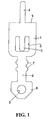
- FIG. 1 shows a top view of a first embodiment of an assembly aid according to the invention O on a greatly enlarged scale.
- brackets for the assembly of which the aid according to the invention is intended, are relative are small components, and accordingly this is in Fig. 1 in a greatly enlarged Component shown on a very small scale. Its total length is approximately 11.5, for example mm, the largest width is about 3.2 mm, the other details are correspondingly small of the component.
- the assembly aid O is made from a sheet metal strip approximately 0.4 mm thick. It comprises a base 1, in which an opening 2 is formed, one at the edge of which the base 1 trained retaining lug 3 begins to anchor and hold one elastomeric O-ring (not shown in Fig. 1) is determined.
- Base 1 is straight Front edge 4, from the middle of which a tongue 5 extends, the end of which is shown Example is rounded. The transition between the tongue 5 and the leading edge 4 should be as sharp as possible in order to align the mounting aid O with the one to be held Bracket not to be affected.
- a flag 6 extends from the end of the base 1 opposite the edge 4 accounts for almost half of the total longitudinal extension of the assembly aid O.
- the Flag 6 is laterally provided with protruding lugs 7 and has a widened at its end Head 8 in which a hole 9 is formed.
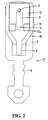
- Fig. 2 shows the assembly aid O of Fig. 1 in its on one in approximately the same scale Bracket attached position.
- the outline of a footplate can be seen from the bracket 10, which runs obliquely with respect to a structure.
- the structure is in Fig. 2 two-part wing 11 a recognizable.
- the structure is largely from a striker spring 12 covered, which runs over a second wing 11 b (see Fig. 3) of the structure and in the a bore 13 is formed. This usually serves as a point of attack for a pointed one Tool to open the striker spring.
- the structure of the bracket is on its side facing away from the base 1 by an O-ring 14 looped, which is held by means of the retaining lug 3 on the base 1.
- This elastomer O-ring 14 secures the assembly aid O to the bracket. How this happens in detail can be seen more precisely in FIG. 3.
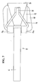
- Fig. 3 shows a bracket from the side, which essentially through its base plate 10, the then rising structure and the curved, a wire receiving slot 15 covering Leaf spring 12 is marked.
- the structure has front 15 on both sides of the slot and rear wings 11a and 11b, of which the rear wing 11b, as already mentioned, is wrapped by the curved striker spring 12.
- the front wing 11a is provided with an undercut 16 on its side facing away from the slot 15, which is hardly recognizable in Fig. 3, since it is covered by the O-ring 14, but in the application form of the invention according to FIG. 4 is better recognizable.
- the undercut 16 is provided with such a bracket, if necessary, to take up a ligature, which wraps around both wings 11a and 11b and a wire inserted into the slot 15 (not shown) spanned and in addition to the action of the spring 12 in the slot 15 guaranteed.
- the wing 11a provided with the undercut 16 is, as can be clearly seen in FIG. 2 can be provided with a slit in the middle and therefore divided into two.
- the mounting aid O is attached to the bracket, which essentially is characterized by the base 1, the flag 6 and the tongue 5.
- the base 1 is attached to the bracket in such a way that its edge region adjacent to the edge 4 in of the undercut 16, the edge 4 abutting the bracket.
- the tongue 5 extends through said slot formed in the front wing 11a and rests on the leaf spring 12, which covers the wire receiving slot 15.
- the holding nose 3 is shaped into a type of eyelet that protrudes upward from the base 1.
- the O-ring 14 is anchored, which is wrapped around the entire bracket structure and pulls the assembly tool O towards the bracket so that the edge 4 at the base 1 n of the undercut 16 lies firmly against the bracket.
- the tongue 5 prevents the assembly aid O swinging up on the bracket.
- the edge 4 in the undercut 16, the tongue 5 on the leaf spring 12 in the closed position and the O-ring 14 together form a device that the inventive assembly aid O in ensures a well-defined, reproducible position on the bracket, from which it is without Destruction of any component can be solved again.
- Fig. 4 shows a modified embodiment of the use of the invention Assembly tool O.
- the O-ring 14 is not around the bracket assembly looped, but is suspended in a hook-shaped anchoring element 17, inserted into the already mentioned bore 13 in the striker spring 12 of the bracket is.
- the hook on the anchoring element 17, in which the O-ring 14 is hooked is possibly closed to the extent that only a narrow gap remains, so that an open eyelet is formed, into which the O-ring 14 is drawn in under stretch can, so that the hook-shaped anchoring part 17 on the O-ring 14 cannot be lost is secured as long as the O-ring does not tear.
- the O-ring 14, which between the assembly aid O and the bracket is clamped, the assembly aid 3 as in the example according to FIG. 3 pulls into a defined position by the in the undercut 16 lying edge 4 and the tongue 5 resting on the leaf spring 12 are determined is.
- FIG 5 shows a further way in which the O-ring 14 can be anchored to the bracket in such a way that that he pulls the assembly tool O into a predetermined position.
- the embodiment of the assembly aid O corresponds again to that of FIGS. 2 to 4, and comparable 4, this embodiment uses a hook-shaped anchoring element 17 for the O-ring 14, which in this case is curved around the from the perspective of the assembly aid O rear wing 11b of the bracket structure and the latter Wing 11b partially enclosing striker spring 12 extends around.
- the hook to which the O-ring 14 is anchored can be closed as far be closed with an eyelet so that the O-ring only extends into the so formed open eyelet.
- the assembly aid O this Embodiment consists of a sheet metal strip that has a rear end that goes to an arc 19 is formed, the inner contour of the outer contour of the on the bracket in The leaf spring 12 in the closed position is adapted and rests on it, the Bow 19 engages under the rear wing 11b of the bracket. At the top of the metal strip a retaining lug 18 is released. At least in the area in which the two-part front wing 11a of the bracket, the sheet metal strip is so narrow that he was in the space between the two parts of the front wing 11 a fits, see Fig. 7. Starting from there extends a flag 6, which is for embedding in acrylic resin to form a cap.
- the assembly aid O is provided by an elastomeric O-ring 14 secured in the bracket by the undercut 16 on the front wing 11 a runs and is anchored to the retaining lug 18. He pulls the assembly tool O into one Defined position in which the inside of the sheet 19 lies closely against the leaf spring 12 and a base 1 adjoining the arch 19 rests on the striker spring 12.
Abstract
Description
Die Korrektur von Zahnfehlstellungen erfolgt mit Hilfe von Brackets, die auf die Zähne des betreffenden Kiefers des Patienten in vorbestimmten Stellungen aufgeklebt und anschließend durch einen elastischen Richtdrahtbogen miteinander verbunden werden. Die Brakkets werden dabei an den einzelnen Zähnen in einer Stellung aufgebracht, die so gewählt ist, dass am Ende der kieferorthopädischen Behandlung der durch die Brackets verlaufende Richtdrahtbogen weitgehend frei von Wellen ist. Am Anfang der Behandlung hat daher der Richtdraht einen sehr komplexen Verlauf. Der dem Kieferbogen folgende relativ große Drahtbogen ist je nach Fehlstellung der Zähne mehr oder weniger in und außerhalb der von ihm beschriebenen Ebene gewellt.The correction of misaligned teeth is done with the help of brackets that are on the teeth of the Affected the patient's jaw in predetermined positions and then can be connected to each other by an elastic arch wire. The brakkets are applied to the individual teeth in a position chosen in this way is that at the end of the orthodontic treatment, the one going through the brackets Straightening wire bow is largely free of waves. Therefore, at the beginning of the treatment Straightening wire a very complex course. The relatively large one following the arch of the jaw Depending on the misalignment of the teeth, the arch wire is more or less in and outside of level described him wavy.
Um die richtige Position der Brackets, in der diese an den Zähnen angeklebt werden sollen, zu ermitteln, gibt es zwei grundsätzliche Verfahren. Eines dieser Verfahren sieht eine optische Vermessung der Kiefer vor. Die aufgenommenen Messwerte werden anschließend mit Hilfe eines Computerprogramms verarbeitet, das nicht nur die Bracketpositionen ermittelt, sondern auch eine Drahtbiegemaschine steuert, mit der ein Satz Richtdrähte unterschiedlicher Querschnitte, die im Verlaufe der Behandlung am Patienten nacheinander zum Einsatz kommen, jeweils in eine relativ komplizierte Gestalten gebogen wird, die die individuelle Fehlstellung der Zähne berücksichtigen. Diese Technik wird insbesondere angewendet, wenn linguale Brackets verwendet werden sollen, weil die Zahnformen auf der lingualen Seite von Individuum zu Individuum sehr verschieden sind und man sich dort nicht am Umriss der Zahnkrone orientieren kann, im Gegensatz zu dem Kronenbild auf der labialen Seite, auf der die Zähne trotz der Individualität der Menschen weitgehend übereinstimmende Formen aufweisen.For the correct position of the brackets in which they should be glued to the teeth, There are two basic methods to determine. One of these methods sees an optical one Surveying the jaw before. The recorded measured values are then with Processed with the help of a computer program that not only determines the bracket positions, but also controls a wire bending machine with which a set of straightening wires different Cross sections that are used one after the other in the course of treatment on the patient come, each one is bent into a relatively complicated shape that suits the individual Take into account the misalignment of the teeth. This technique is used in particular if lingual brackets are to be used because the tooth shapes on the lingual Side are very different from individual to individual and you don't look at the outline there the tooth crown can orient, in contrast to the crown image on the labial Side on which the teeth largely match despite the individuality of the people Have shapes.
Die genannte Computertechnik ist außerordentlich teuer, sie verlangt Investitionen in der
Größenordnung von 100.000 ![]()
![]()
Das gebräuchlichere Verfahren zur Festlegung der Bracketpositionen auf den Zähnen ist die sogenannte Hiro-Technik. Dabei wird zunächst vom Kieferorthopäden ein Abdruck von dem zu korrigierenden Gebiss gemacht. Aus diesem Abdruck wird im Zahntechniklabor ein Gipsabguss des zu korrigierenden Gebisses gefertigt. Dieser Abguss wird in die einzelnen Zähne zersägt und mit Hilfe von Wachs so wieder zusammengesetzt, dass sich die perfekte Okklusion ergibt, die durch die kieferorthopädische Behandlung erreicht werden soll. Anschließend wird der Richtdrahtbogen erstellt, auf dem Drahtbogen werden Brackets angebracht, und der Bogen wird zusammen mit den Brackets so an der lingualen Seite des korrigierten Abgusses in Position gebracht, dass die Brackets den Zähnen in vorgeschriebener Weise gegenüberstehen, wobei zwischen den Brackets und den Zähnen ein bestimmter Abstand eingehalten wird, der später mit einer Vergussmasse ausgefüllt werden soll. Sodann werden mit einem lichthärtenden Acrylharz einzelne Käppchen über jeder Zahnschneide geformt, die sich bis zu den Brackets erstrecken und an diesen anhaften. Nach dem Aushärten der Käppchen werden die Brackets vom Richtdraht heruntergenommen. Sodann werden die Käppchen mit den daran hängenden Brackets einzeln wieder auf die Zähne des korrigierten Abgusses aufgesetzt, und die Zwischenräume zwischen den Fußplatten der Brackets und den Zahnkronen werden mit einer härtenden Vergussmasse ausgefüllt, womit eine sog. individuelle Basis für jedes Bracket erstellt ist. Es versteht sich, dass dabei ein Trennmittel an den Zähnen des korrigierten Abgusses verwendet wird, um ein Anhaften der Vergussmasse an den Zähnen zu vermeiden.The more common method of setting bracket positions on teeth is the so-called hiro technique. The orthodontist first makes an impression of the bit to be corrected. This impression is used in the dental technology laboratory Plaster cast of the denture to be corrected. This cast is in the individual Sawed teeth and reassembled with the help of wax so that the perfect Occlusion results, which should be achieved by orthodontic treatment. Subsequently the straightening wire arch is created, brackets are attached to the wire arch, and the arch is corrected along with the brackets on the lingual side of the Cast that positioned the brackets in the prescribed teeth Face each other, with a certain one between the brackets and the teeth Distance is maintained, which is later to be filled with a potting compound. thereupon with a light-curing acrylic resin, individual copings over each tooth cutting edge shaped, which extend to the brackets and adhere to them. To As the copings harden, the brackets are removed from the straightening wire. Then the copings with the brackets attached to them are individually put back on the Teeth of the corrected cast are placed, and the gaps between the footplates the brackets and the tooth crowns are filled with a hardening casting compound, which creates a so-called individual basis for each bracket. It goes without saying that a release agent is used on the teeth of the corrected casting in order to to prevent the casting compound from sticking to the teeth.
Nach Abschluss dieser vorbereitenden Laborarbeiten wird der Satz Brackets vom Kieferorthopäden unter Verwendung eines dünnen Kleberfilms auf den zugehörigen Zähnen des zu korrigierenden Gebisses festgeklebt, wobei die Käppchen wiederum als Lehren dienen, die die Brackets auf den Zähnen so positionieren, wie sie am korrigierten Gipsabguss positioniert waren. Nach dem Aushärten des Klebers werden die Käppchen weggebrochen, was eine zeitaufwendige Arbeit ist, weil das Acrylmaterial vollständig von den Brackets entfernt werden muss.After completing this preparatory laboratory work, the set of brackets is used by the orthodontist using a thin film of adhesive on the associated teeth of the corrective denture glued, the caps in turn serve as lessons that Position the brackets on the teeth as they are positioned on the corrected plaster cast were. After the glue has hardened, the caps are broken away, what is a time consuming job because the acrylic material is completely removed from the brackets must become.
Nachteilig bei beiden Verfahrensweisen ist, dass es nach dem unbeabsichtigten Lösen eines Bracket von einem Zahn während der gesamten kieferorthopädischen Korrekturbehandlung schwierig ist, das betreffende Bracket wieder an den Zahn vorschriftsmäßig anzubringen. Diese Arbeit kann nur unter Einsatz des Labors durchgeführt werden. Es ist bei Computervermessung eine vollkommen neue Vermessung erforderlich, und es muss ein neuer Drahtsatz angefertigt werden, weil der Patient in aller Regel nicht sofort seinen Kieferorthopäden aufsucht und sich die Zahnstellungskorrektur in der Zwischenzeit rückstellen kann. Das unbeabsichtigte Lösen eines Bracket ist gar nicht so selten. Es kommt bei jedem Patienten in der Regel einmal während der Behandlungsdauer vor. Bei der Hiro-Technik muss anhand des Richtdrahtbogens im Labor für ein neues Bracket eine neue individuelle Basis einschließlich einer Acrylkappe gefertigt werden.A disadvantage of both procedures is that after an unintentional release of one Bracket of one tooth during the entire orthodontic corrective treatment it is difficult to properly re-attach the bracket in question to the tooth. This work can only be carried out using the laboratory. It is at Computer surveying requires a completely new survey and it must be one new wire sets are made because the patient usually does not immediately contact his orthodontist visits and reset the tooth position correction in the meantime can. Unintentionally loosening a bracket is not that rare. It comes with everyone Patients usually before once during the treatment period. With the Hiro technology must use the straightening wire bow in the laboratory for a new individual bracket Base including an acrylic cap can be made.
Der Erfindung liegt daher die Aufgabe zugrunde, hier eine Abhilfe zu schaffen und eine Einrichtung anzugeben, die es erlaubt, ein von einem Zahn abgelöstes Bracket ohne Zuhilfenahme des Zahntechniklabors wieder an dem Zahn anzubringen.The invention is therefore based on the object to provide a remedy here and a device Specify that allows a bracket detached from a tooth to be used without aid of the dental technology laboratory to be attached to the tooth again.
Die von der Erfindung angegebene Lösung schafft ein Montagehilfsmittel für die Befestigung eines kieferorthopädischen Bracket an einem Zahn, bestehend aus einem Blechstreifen, der Einrichtungen zur formschlüssigen Anlage an dem Bracket, eine Halteeinrichtung zum Verankern einer elastischen Spanneinrichtung an dem Blechstreifen für die Fixierung des Blechstreifens an dem Bracket und eine sich von der Halteeinrichtung weg erstreckende Fahne aufweist.The solution specified by the invention creates an assembly aid for the attachment an orthodontic bracket on a tooth, consisting of a metal strip, the devices for positive engagement with the bracket, a holding device for anchoring an elastic tensioning device to the sheet metal strip for fixation of the metal strip on the bracket and one extending away from the holding device Has flag.
Dieser Blechstreifen ist dazu geeignet, die Hiro-Technik so auszugestalten, dass auf eine Zerstörung der erläuterten Acrylkäppchen verzichtet werden kann, so dass diese für die spätere Wiederanbringung gelöster Brackets bereitgehalten werden können.This metal strip is suitable for designing the Hiro technology so that it Destruction of the explained acrylic cap can be dispensed with, so that this for the later reattachment of released brackets can be kept ready.
Die Verfahrensweise bei Einsatz der Erfindung ist nämlich wie folgt. Es wird in der bei der Hiro-Technik üblichen Weise zunächst ein Abdruck vom Gebiss gemacht, davon ein Abguss erstellt und dieser zersägt. Die Zähne des Abgusses werden zur perfekten Okklusion wieder zusammengesetzt und dann der Drahtbogen erstellt. Bevor nun die Brackets an dem Drahtbogen angebracht werden, oder danach, wird an jedem Bracket das erfindungsgemäßen Montagehilfsmittel angebracht. Dieses ist so gestaltet, dass es am Bracket in einer stabilen Stellung anliegt. Ihre Fahne erstreckt sich in Richtung auf die Okklusalebene der Zähne und vorzugsweise über diese hinaus. Sodann werden in der üblichen Weise mit lichthärtendem Acrylharz die genannten Käppchen an den Zähnen geformt, jedoch mit dem Unterschied gegenüber der bekannten Technik, dass die Käppchen nur die Fahne einbetten, nicht aber das an dem Montagehilfsmittel befestigte Bracket. Anschließend wird das Acrylharz ausgehärtet.The procedure when using the invention is namely as follows. It is in the case of the Hiro technology first made an impression of the dentition, of which a cast created and this sawed. The teeth of the cast become the perfect occlusion reassembled and then the wire arch created. Before the brackets be attached to the wire arch, or afterwards, the bracket according to the invention Assembly aids attached. This is designed so that it is in a bracket stable position. Your flag extends in the direction of the occlusal plane of the teeth and preferably beyond them. Then in the usual way with light-curing acrylic resin molded the copings mentioned on the teeth, but with the Difference from the known technique that the caps only embed the flag, but not the bracket attached to the assembly aid. Then that will Hardened acrylic resin.
Die weitere Verarbeitung sieht dann in üblicher Weise die Erstellung der individuellen Basis an jedem Bracket vor. Der so fertiggestellte Bracketsatz wird zusammen mit den daran angebrachten, in die Käppchen eingebetteten, erfindungsgemäßen Montagehilfsmitteln dem Kieferorthopäden zur Verfügung gestellt, der die Brackets an den fehlstehenden Zähnen in Stellung bringt. Die Käppchen mit den daran haftenden Montagehilfsmitteln bilden somit Montagelehren für die Anbringung der Brackets in vorbestimmten Stellungen an den Zähnen, in denen die Brackets vom Kieferorthopäden mittels eines dünnen Kleberfilms an den Zähnen angeklebt werden. Nach dem Aushärten des Klebers löst der Kieferorthopäde die Montagelehren von den Brackets. Es ist hierzu nicht erforderlich, irgend etwas zu zerstören.Further processing then sees the creation of the individual basis in the usual way on each bracket. The bracket set thus completed, together with the attached embedded in the cap, assembly aids according to the invention Orthodontist provided the brackets on the missing teeth in Position. The caps with the assembly aids attached to them thus form Assembly gauges for the attachment of the brackets in predetermined positions on the teeth, in which the brackets are attached to the orthodontist using a thin adhesive film Teeth are glued. After the adhesive has hardened, the orthodontist removes the Assembly gauges from the brackets. It is not necessary to destroy anything.
Der Kieferorthopäde hebt die mit individuellen Kennzeichnungen versehenen Montagelehren auf, so dass er sie später wieder verwenden kann, wenn es notwendig werden sollte, weil sich ein Bracket von einem Zahn gelöst hat.The orthodontist lifts the assembly gauges with individual markings so that he can use it again later if it becomes necessary because a bracket has come off a tooth.
Das erfindungsgemäße Bauteil, d.h. das Montagehilfsmittel, muss selbstverständlich an den Typ des verwendeten Bracket angepasst sein, damit sichergestellt ist, dass das Brakket und das Montagehilfsmittel eine vorbestimmte Stellung zueinander in reproduzierbarer Weise einnehmen. Das erfindungsgemäße Montagehilfsmittel weist daher Einrichtungen zur formschlüssigen Anlage an dem Bracket und Halteeinrichtungen zur Verankerung einer Spanneinrichtung auf, die das Montagehilfsmittel an dem Bracket lösbar festlegt. Vorzugsweise ist die Spanneinrichtung an dem Montagehilfsmittel unverlierbar verankert, was die Handhabung erleichtert. Sie kann ein elastomerer O-Ring oder eine Feder, etwa ein Federring, eine Bügelfeder oder eine Schraubenfeder mit Ösen an ihren Enden, seinThe component according to the invention, i.e. the assembly tool, of course be adapted to the type of bracket used to ensure that the bracket and the assembly aid a predetermined position to each other in a reproducible Ingest way. The assembly aid according to the invention therefore has facilities for a positive fit on the bracket and holding devices for anchoring Clamping device that releasably fixes the assembly aid on the bracket. Preferably the tensioning device is anchored captively on the assembly aid, which is the Handling made easier. It can be an elastomeric O-ring or a spring, such as a spring ring, a bow spring or a coil spring with eyelets at its ends
Bei einer Verwendungsart der Erfindung umgreift die Spannvorrichtung, etwa der erwähnte O-Ring den Bracketaufbau. Bei einer alternativen Verwendungsart ist an der Spanneinrichtung, insbesondere dem Spannring ein Verankerungsteil angebracht, insbesondere in Form eines Hakens und vorzugsweise unverlierbar, wobei dieses Verankerungsteil dafür bestimmt ist, an dem Bracket lösbar verankert zu werden. Beispielsweise kann das Verankerungsteil den Bracketaufbau übergreifen oder es kann beispielsweise in eine Öffnung eingeführt werden, die an einer Schließfeder eines selbstligierenden Bracket ausgebildet ist und dort gewöhnlich zum Einsetzen eines Werkzeugs bestimmt ist, mit dem die Schließfeder vom Kieferorthopäden geöffnet und geschlossen wird.In one type of use of the invention, the clamping device, such as the one mentioned, engages O-ring the bracket structure. In an alternative type of use, on the tensioning device, in particular anchoring part attached to the clamping ring, in particular in Shape of a hook and preferably captive, this anchoring part for it is intended to be releasably anchored to the bracket. For example, the anchoring part overlap the bracket structure or it can, for example, into an opening be introduced, which is formed on a closing spring of a self-ligating bracket and there is usually intended for inserting a tool with which the closing spring is opened and closed by the orthodontist.
Die an dem Blechstreifen ausgebildete Fahne ist vorzugsweise so lang, dass sie nach dem Anbringen des Käppchens aus diesem vorsteht. Sie kann dann leicht mit einer Pinzette oder Zange ergriffen werden. Zu diesem Zweck kann die Fahne an ihrem aus dem Käppchen vorstehenden Ende verbreitert sein. Auch ist es vorteilhaft, wenn die Fahne seitlich vorstehende Nasen aufweist, die die Verankerung des das Käppchen bildenden Acrylharzes an der Fahne verbessert.The flag formed on the sheet metal strip is preferably so long that after the Attach the cap protruding from this. You can then easily use tweezers or pliers. For this purpose, the flag can be attached to your out of the cap protruding end to be widened. It is also advantageous if the flag is on the side has protruding lugs, which anchor the acrylic resin forming the cap improved on the flag.
Die Erfindung wird nachfolgend unter Bezugnahme auf in den Zeichnungen dargestellten Ausführungsbeispielen näher erläutert. Es zeigt:
- Fig. 1
- eine Draufsicht auf ein erfindungsgemäßes Montagehilfsmittel gemäß einer ersten Ausführungsform der Erfindung;
- Fig. 2
- eine Draufsicht auf das an einem Bracket angebrachte Montagehilfsmittel nach Fig. 1;
- Fig. 3
- eine Seitenansicht eines Bracket mit einem daran angebrachten Montagehilfsmittel nach Fig. 1;
- Fig. 4
- eine Seitenansicht eines Bracket mit einem daran angebrachten Montagehilfsmittel ähnlich Fig. 1 mit zusätzlicher Verankerungsvorrichtung;
- Fig. 5
- eine Seitenansicht eines Brackets mit daran angebrachtem Montagehilfsmittel ähnlich Fig. 4 mit einer abgewandelten Verankerungseinrichtung;
- Fig. 6
- eine Seitenansicht eines Bracket mit einem daran angebrachten Montagehilfsmittel gemäß einer zweiten Ausführungsform der Erfindung, und
- Fig. 7
- eine Draufsicht auf die Anordnung von Fig. 6.
- Fig. 1
- a plan view of an inventive assembly aid according to a first embodiment of the invention;
- Fig. 2
- a plan view of the mounting aid attached to a bracket according to FIG. 1;
- Fig. 3
- a side view of a bracket with an attached mounting aid according to FIG. 1;
- Fig. 4
- a side view of a bracket with an attached mounting aid similar to Figure 1 with additional anchoring device.
- Fig. 5
- a side view of a bracket with attached mounting aids similar to Figure 4 with a modified anchoring device.
- Fig. 6
- a side view of a bracket with an attached mounting aid according to a second embodiment of the invention, and
- Fig. 7
- 6 shows a plan view of the arrangement from FIG. 6.
Fig. 1 zeigt in Draufsicht eine erste Ausführungsform eines erfindungsgemäßen Montagehilfsmittels O in stark vergrößertem Maßstab. In diesem Zusammenhang ist anzumerken, dass Brackets, für deren Montage das erfindungsgemäße Hilfsmittel bestimmt ist, relativ kleine Bauteile sind, und dementsprechend ist auch das in Fig. 1 in stark vergrößerndem Maßstab gezeigte Bauteil sehr klein. Seine Gesamtlänge beträgt beispielsweise etwa 11,5 mm, die größte Breite beträgt etwa 3,2 mm, entsprechend klein sind die übrigen Einzelheiten des Bauteils.1 shows a top view of a first embodiment of an assembly aid according to the invention O on a greatly enlarged scale. In this context it should be noted that brackets, for the assembly of which the aid according to the invention is intended, are relative are small components, and accordingly this is in Fig. 1 in a greatly enlarged Component shown on a very small scale. Its total length is approximately 11.5, for example mm, the largest width is about 3.2 mm, the other details are correspondingly small of the component.
Das Montagehilfsmittel O ist aus einem Blechstreifen von etwa 0,4 mm Dicke hergestellt.
Es umfasst eine Basis 1, in der ein Durchbruch 2, ausgebildet ist, an dessen Rand eine an
der Basis 1 ausgebildete Haltenase 3 beginnt, die zum Verankern und Festhalten eines
elastomeren O-Ringes (in Fig. 1 nicht dargestellt) bestimmt ist. Die Basis 1 hat eine gerade
Vorderkante 4, von deren Mitte sich eine Zunge 5 erstreckt, deren Ende im dargestellten
Beispiel verrundet ist. Der Übergang zwischen der Zunge 5 und der Vorderkante 4 soll
möglichst scharfkantig sein, um die Ausrichtung des Montagehilfsmittels O an dem zu haltendem
Bracket nicht zu beeinträchtigen.The assembly aid O is made from a sheet metal strip approximately 0.4 mm thick.
It comprises a
Von dem der Kante 4 entgegengesetzten Ende der Basis 1 erstreckt sich eine Fahne 6, die
knapp die Hälfte der Gesamtlängserstreckung des Montagehilfsmittels O ausmacht. Die
Fahne 6 ist seitlich mit vorstehenden Nasen 7 versehen und hat an ihrem Ende einen verbreiterten
Kopf 8, in dem ein Loch 9 ausgebildet ist.A
Fig. 2 zeigt in etwa gleichem Maßstab das Montagehilfsmittel O von Fig. 1 in seiner an einem
Bracket angebrachten Stellung. Von dem Bracket erkennt man die Umrisse einer Fußplatte
10, die gegenüber einem Aufbau schräg verläuft. Von dem Aufbau ist in Fig. 2 ein
zweigeteilter Flügel 11 a erkennbar. Der Aufbau wird weitgehend von einer Schließblattfeder
12 überdeckt, die über einen zweiten Flügel 11 b (siehe Fig. 3) des Aufbaus läuft und in der
eine Bohrung 13 ausgebildet ist. Diese dient üblicherweise als Angriffsstelle für ein spitzes
Werkzeug zum Öffnen der Schließblattfeder.Fig. 2 shows the assembly aid O of Fig. 1 in its on one in approximately the same scale
Bracket attached position. The outline of a footplate can be seen from the
Der Aufbau des Bracket wird an seiner der Basis 1 abgewandten Seite von einem O-Ring
14 umschlungen, der mittels der Haltenase 3 an der Basis 1 gehalten ist. Dieser elastomere
O-Ring 14 sichert das Montagehilfsmittel O an dem Bracket. Wie dieses im Einzelnen geschieht,
ist genauer in Fig. 3 zu erkennen.The structure of the bracket is on its side facing away from the
Fig. 3 zeigt ein Bracket von der Seite, das im wesentlichen durch seine Fußplatte 10, den
sich darauf erhebenden Aufbau und die einen Drahtaufnahmeschlitz 15 überdeckende, gebogene
Blattfeder 12 gekennzeichnet ist. Der Aufbau weist beidseitig des Schlitzes 15 vordere
und hintere Flügel 11a bzw. 11b auf, von denen der hintere Flügel 11b, wie bereits
erwähnt, von der gebogenen Schließblattfeder 12 umschlungen ist. Der vordere Flügel 11a
ist an seiner dem Schlitz 15 abgewandten Seite mit einer Hinterschneidung 16 versehen ist,
die in Fig. 3 kaum erkennbar ist, da sie von dem O-Ring 14 verdeckt ist, aber in der Anwendungsform
der Erfindung nach Fig. 4 besser erkennbar ist. Die Hinterschneidung 16 ist
bei einem solchen Bracket dazu vorgesehen, gegebenenfalls eine Ligatur aufzunehmen,
die beide Flügel 11a und 11b umschlingt und einen in den Schlitz 15 eingelegten Draht
(nicht dargestellt) überspannt und zusätzlich zur Wirkung der Feder 12 in dem Schlitz 15
sichert.Fig. 3 shows a bracket from the side, which essentially through its
Der mit der Hinterschneidung 16 versehene Flügel 11a ist, wie man in Fig. 2 klar erkennen
kann, in der Mitte mit einem Schlitz versehen und daher zweigeteilt.The
An dem Bracket ist das erfindungsgemäße Montagehilfsmittel O angebracht, das im wesentlichen
durch die Basis 1, die Fahne 6 und die Zunge 5 gekennzeichnet ist. Die Basis 1
ist an dem Bracket derart angebracht, dass ihr der Kante 4 benachbarter Randbereich in
der Hinterschneidung 16 liegt, wobei die Kante 4 an das Bracket anstößt. Die Zunge 5 erstreckt
sich durch den genannten Schlitz, der in dem vorderen Flügel 11a ausgebildet ist,
und liegt auf der Blattfeder 12 auf, die den Drahtaufnahmeschlitz 15 überdeckt. Die Haltenase
3 ist zu einer Art Öse geformt, die nach oben von der Basis 1 vorsteht. An der Haltenase
3 ist der O-Ring 14 verankert, der um den gesamten Bracketaufbau geschlungen ist
und das Montagehilfsmittel O an das Bracket heranzieht, so dass die Kante 4 an der Basis
1 n der Hinterschneidung 16 am Bracket fest anliegt. Die Zunge 5 hindert das Montagehilfsmittel
O daran, an dem Bracket hochzuschwenken. Die Kante 4 in der Hinterschneidung
16, die Zunge 5 auf der in Schließstellung befindlichen Blattfeder 12 und der O-Ring
14 bilden zusammen eine Einrichtung, die das erfindungsgemäße Montagehilfsmittel O in
einer wohldefinierten, reproduzierbaren Stellung an dem Bracket sichert, aus der es ohne
Zerstörung irgendwelcher Bestandteile wieder gelöst werden kann.The mounting aid O according to the invention is attached to the bracket, which essentially
is characterized by the
Fig. 4 zeigt eine abgewandelte Ausführungsform der Verwendung des erfindungsgemäßen
Montagehilfsmittels O. Bei dieser Ausführungsform ist der O-Ring 14 nicht um dem Brakketaufbau
geschlungen, sondern ist in ein hakenförmiges Verankerungselement 17 eingehängt,
das in die schon erwähnte Bohrung 13 in der Schließblattfeder 12 des Bracket eingesteckt
ist. Der Haken an dem Verankerungselement 17, in den der O-Ring 14 eingehängt
ist, kann gegebenenfalls soweit geschlossen sein, dass nur ein schmaler Spalt verbleibt, so
dass eine offene Öse gebildet wird, in den der O-Ring 14 unter Dehnung eingezogen werden
kann, so dass das hakenförmige Verankerungsteil 17 an den O-Ring 14 unverlierbar
gesichert ist, solange der O-Ring nicht reißt. Man erkennt, dass der O-Ring 14, der zwischen
dem Montagehilfsmittel O und dem Bracket eingespannt ist, das Montagehilfsmittel
O wie beim Beispiel nach Fig. 3 in eine definierte Stellung zieht, die durch die in der Hinterschneidung
16 liegende Kante 4 und die auf der Blattfeder 12 aufliegende Zunge 5 bestimmt
ist.Fig. 4 shows a modified embodiment of the use of the invention
Assembly tool O. In this embodiment, the O-
Fig. 5 zeigt eine weitere Art, wie der O-Ring 14 an dem Bracket so verankert werden kann,
dass er das Montagehilfsmittel O in eine vorbestimmte Stellung zieht. Die Ausführungsform
des Montagehilfsmittels O entspricht wieder jener nach den Fig. 2 bis 4, und vergleichbar
dem Beispiel nach Fig. 4 verwendet diese Ausführungsform ein hakenförmiges Verankerungselement
17 für den O-Ring 14, das sich in diesem Falle jedoch bogenförmig um den
aus Sicht des Montagehilfsmittels O hinteren Flügel 11b des Bracketaufbaus und der diesen
Flügel 11b teilweise umschließenden Schließblattfeder 12 herum erstreckt. Auch bei
dieser Ausführungsform kann der Haken, an dem der O-Ring 14 verankert ist, soweit zu
einer Öse geschlossen sein, dass sich der O-Ring nur unter Dehnung in die so gebildete
offene Öse einziehen lässt.5 shows a further way in which the O-
Die Fig. 6 und 7 zeigen eine zweite Ausführungsform der Erfindung, die an ein Bracket eines
vorgegebenen Typs in besonderer Weise angepasst ist. Das Montagehilfmittel O dieser
Ausführungsform besteht aus einem Blechstreifen, der ein hinteres Ende aufweist, das zu
einem Bogen 19 geformt ist, dessen Innenkontur der Außenkontur der auf dem Bracket in
Schließstellung befindlichen Blattfeder 12 angepasst ist und auf dieser aufliegt, wobei der
Bogen 19 unter den hinteren Flügel 11b des Bracket greift. An der Oberseite des Blechstreifens
ist eine Haltenase 18 ausgeklinkt. Wenigstens in dem Bereich, in dem sich der
zweigeteilte vordere Flügel 11a des Bracket befindet, ist der Blechstreifen so schmal ausgebildet,
dass er in den Zwischenraum zwischen den beiden Teilen des vorderen Flügels
11 a passt, siehe Fig. 7. Von dort ausgehend erstreckt sich eine Fahne 6, die zum Einbetten
in Acrylharz zur Bildung eines Käppchens bestimmt ist.6 and 7 show a second embodiment of the invention attached to a bracket
predefined type is adapted in a special way. The assembly aid O this
Embodiment consists of a sheet metal strip that has a rear end that goes to
an
Wie die Fig. 6 und 7 zeigen, wird das Montagehilfsmittel O durch einen elastomeren O-Ring
14 in dem Bracket gesichert, der durch die Hinterschneidung 16 an dem vorderen Flügel
11 a verläuft und an der Haltenase 18 verankert ist. Er zieht das Montagehilfsmittel O in eine
definierte Position, in der die Innenseite des Bogens 19 eng an der Blattfeder 12 anliegt und
eine sich an den Bogen 19 anschließende Basis 1 auf der Schließblattfeder 12 aufliegt.As FIGS. 6 and 7 show, the assembly aid O is provided by an elastomeric O-
Claims (11)
Priority Applications (5)
| Application Number | Priority Date | Filing Date | Title |
|---|---|---|---|
| AT02013758T ATE291385T1 (en) | 2002-06-20 | 2002-06-20 | ASSEMBLY AID FOR ATTACHING AN ORTHODONTIC BRACKET |
| EP02013758A EP1374795B1 (en) | 2002-06-20 | 2002-06-20 | Mounting aid means for the fixation of an orthodontic bracket |
| DE50202544T DE50202544D1 (en) | 2002-06-20 | 2002-06-20 | Mounting aid for the attachment of an orthodontic bracket |
| JP2003175415A JP4058386B2 (en) | 2002-06-20 | 2003-06-19 | Orthodontic bracket mounting aid |
| US10/600,374 US7044733B2 (en) | 2002-06-20 | 2003-06-20 | Mounting aid for mounting an orthodontic bracket to a tooth |
Applications Claiming Priority (1)
| Application Number | Priority Date | Filing Date | Title |
|---|---|---|---|
| EP02013758A EP1374795B1 (en) | 2002-06-20 | 2002-06-20 | Mounting aid means for the fixation of an orthodontic bracket |
Publications (2)
| Publication Number | Publication Date |
|---|---|
| EP1374795A1 true EP1374795A1 (en) | 2004-01-02 |
| EP1374795B1 EP1374795B1 (en) | 2005-03-23 |
Family
ID=29716811
Family Applications (1)
| Application Number | Title | Priority Date | Filing Date |
|---|---|---|---|
| EP02013758A Expired - Lifetime EP1374795B1 (en) | 2002-06-20 | 2002-06-20 | Mounting aid means for the fixation of an orthodontic bracket |
Country Status (5)
| Country | Link |
|---|---|
| US (1) | US7044733B2 (en) |
| EP (1) | EP1374795B1 (en) |
| JP (1) | JP4058386B2 (en) |
| AT (1) | ATE291385T1 (en) |
| DE (1) | DE50202544D1 (en) |
Cited By (2)
| Publication number | Priority date | Publication date | Assignee | Title |
|---|---|---|---|---|
| EP2374429A1 (en) | 2010-04-08 | 2011-10-12 | Wolfgang Heiser | Fitting assembly with aid and orthodontic bracket |
| WO2017148749A1 (en) * | 2016-03-01 | 2017-09-08 | Christoph Von Mandach | Orthodontic bracket |
Families Citing this family (5)
| Publication number | Priority date | Publication date | Assignee | Title |
|---|---|---|---|---|
| WO2007069881A1 (en) * | 2005-12-12 | 2007-06-21 | Grotech B.V. | Indirect bonding device for bonding orthodontic brackets on teeth, method for manufacturing such device and method for bonding orthodontic brackets on teeth |
| US20080305450A1 (en) * | 2007-06-06 | 2008-12-11 | Gestenco International Ab | Placement jig for an orthodontic device |
| JP4956339B2 (en) * | 2007-09-07 | 2012-06-20 | 第一電子工業株式会社 | Connector device |
| US20180071057A1 (en) * | 2017-09-12 | 2018-03-15 | Robert T Rudman | Programmable orthodontic indexing guide and bracket pin assembly and method of use |
| KR101999378B1 (en) * | 2017-10-27 | 2019-07-11 | 주식회사 디오 | apparatus for orthodontics treatment |
Citations (3)
| Publication number | Priority date | Publication date | Assignee | Title |
|---|---|---|---|---|
| US4626208A (en) * | 1985-08-16 | 1986-12-02 | Tp Orthodontics, Inc. | Positioning jig for edgewise bracket |
| US5542842A (en) * | 1992-11-09 | 1996-08-06 | Ormco Corporation | Bracket placement jig assembly and method of placing orthodontic brackets on teeth therewith |
| WO2000036989A1 (en) * | 1998-12-18 | 2000-06-29 | 3M Innovative Properties Company | Method and apparatus for precise bond placement of orthodontic appliances |
Family Cites Families (5)
| Publication number | Priority date | Publication date | Assignee | Title |
|---|---|---|---|---|
| US3521355A (en) * | 1969-06-30 | 1970-07-21 | Lawrence Pearlman | Positioning means for orthodontic brackets |
| US3787976A (en) * | 1972-05-30 | 1974-01-29 | H Cohen | Calibrated bracket securing means |
| IT1126508B (en) * | 1979-12-07 | 1986-05-21 | Giovanni Drisaldi | POSITIONING AND PROTECTION DEVICE FOR AN ORTHODONTIC ATTACK |
| KR100379987B1 (en) * | 2000-08-25 | 2003-04-16 | 조재형 | Convertable resin core system for positioning a bracket at a predetermined point of tooth surface |
| US7094053B2 (en) * | 2002-05-28 | 2006-08-22 | Ormco Corporation | Custom jig for placing orthodontic brackets and methods of making and using same |
-
2002
- 2002-06-20 DE DE50202544T patent/DE50202544D1/en not_active Expired - Lifetime
- 2002-06-20 EP EP02013758A patent/EP1374795B1/en not_active Expired - Lifetime
- 2002-06-20 AT AT02013758T patent/ATE291385T1/en not_active IP Right Cessation
-
2003
- 2003-06-19 JP JP2003175415A patent/JP4058386B2/en not_active Expired - Fee Related
- 2003-06-20 US US10/600,374 patent/US7044733B2/en not_active Expired - Fee Related
Patent Citations (3)
| Publication number | Priority date | Publication date | Assignee | Title |
|---|---|---|---|---|
| US4626208A (en) * | 1985-08-16 | 1986-12-02 | Tp Orthodontics, Inc. | Positioning jig for edgewise bracket |
| US5542842A (en) * | 1992-11-09 | 1996-08-06 | Ormco Corporation | Bracket placement jig assembly and method of placing orthodontic brackets on teeth therewith |
| WO2000036989A1 (en) * | 1998-12-18 | 2000-06-29 | 3M Innovative Properties Company | Method and apparatus for precise bond placement of orthodontic appliances |
Cited By (2)
| Publication number | Priority date | Publication date | Assignee | Title |
|---|---|---|---|---|
| EP2374429A1 (en) | 2010-04-08 | 2011-10-12 | Wolfgang Heiser | Fitting assembly with aid and orthodontic bracket |
| WO2017148749A1 (en) * | 2016-03-01 | 2017-09-08 | Christoph Von Mandach | Orthodontic bracket |
Also Published As
| Publication number | Publication date |
|---|---|
| JP2004033762A (en) | 2004-02-05 |
| EP1374795B1 (en) | 2005-03-23 |
| US20040013992A1 (en) | 2004-01-22 |
| JP4058386B2 (en) | 2008-03-05 |
| DE50202544D1 (en) | 2005-04-28 |
| US7044733B2 (en) | 2006-05-16 |
| ATE291385T1 (en) | 2005-04-15 |
Similar Documents
| Publication | Publication Date | Title |
|---|---|---|
| EP2374429B1 (en) | Fitting assembly with aid and orthodontic bracket | |
| DE3035829C2 (en) | Device for attaching an orthodontic attachment | |
| EP1234549A1 (en) | Lingual bracket | |
| DE10324412A1 (en) | Custom-made clamping device for the placement of orthodontic brackets and their manufacturing and application methods | |
| DE1228754B (en) | Process for attaching orthodontic or orthodontic appliances and removable dentures using so-called >> attachments << and devices for this | |
| DE102005019273A1 (en) | Orthodontic molar brackets with swiveling bracket overlap | |
| DE102005020082A1 (en) | Torque spring for double-wire orthodontic treatment | |
| DE212014000061U1 (en) | Static self-ligating orthodontic braces | |
| EP1379193B1 (en) | Orthodontic appliance | |
| EP1909683A1 (en) | Lingual retainer | |
| EP1374795B1 (en) | Mounting aid means for the fixation of an orthodontic bracket | |
| DE60034686T2 (en) | DEVICE FOR HOLDING AN ELASTIC LOOP AND MANUFACTURING METHOD | |
| EP3826572B1 (en) | Drilling jig for jaw surgery | |
| EP1332726A1 (en) | Orthodontic appliance | |
| DE102012220054A1 (en) | Orthodontic device for the forward displacement of the lower jaw | |
| DE3831292C2 (en) | ||
| CH712244A2 (en) | Orthodontic bracket. | |
| DE19632084C1 (en) | Cofferdam brace for use in dentistry | |
| DE102004043200B4 (en) | Denture for insertion in the region of a tooth gap | |
| DE102012103469B4 (en) | telescopic crown | |
| DE102017104813A1 (en) | retainer | |
| DE3318825C2 (en) | Device for positioning a lingual bracket | |
| DE2741550A1 (en) | Orthodontic treatment of teeth in laboratory - gluing feet on bracket with negative impressions onto fixing marks previously marked out of teeth in mouth | |
| DE10116063B4 (en) | Rubber dam and fasteners | |
| WO1996041586A1 (en) | Device for treating a bone recess |
Legal Events
| Date | Code | Title | Description |
|---|---|---|---|
| PUAI | Public reference made under article 153(3) epc to a published international application that has entered the european phase |
Free format text: ORIGINAL CODE: 0009012 |
|
| AK | Designated contracting states |
Kind code of ref document: A1 Designated state(s): AT BE CH CY DE DK ES FI FR GB GR IE IT LI LU MC NL PT SE TR |
|
| AX | Request for extension of the european patent |
Extension state: AL LT LV MK RO SI |
|
| 17P | Request for examination filed |
Effective date: 20040623 |
|
| AKX | Designation fees paid |
Designated state(s): AT BE CH CY DE DK ES FI FR GB GR IE IT LI LU MC NL PT SE TR |
|
| GRAP | Despatch of communication of intention to grant a patent |
Free format text: ORIGINAL CODE: EPIDOSNIGR1 |
|
| GRAS | Grant fee paid |
Free format text: ORIGINAL CODE: EPIDOSNIGR3 |
|
| GRAA | (expected) grant |
Free format text: ORIGINAL CODE: 0009210 |
|
| AK | Designated contracting states |
Kind code of ref document: B1 Designated state(s): AT BE CH CY DE DK ES FI FR GB GR IE IT LI LU MC NL PT SE TR |
|
| PG25 | Lapsed in a contracting state [announced via postgrant information from national office to epo] |
Ref country code: GB Free format text: LAPSE BECAUSE OF FAILURE TO SUBMIT A TRANSLATION OF THE DESCRIPTION OR TO PAY THE FEE WITHIN THE PRESCRIBED TIME-LIMIT Effective date: 20050323 Ref country code: FI Free format text: LAPSE BECAUSE OF FAILURE TO SUBMIT A TRANSLATION OF THE DESCRIPTION OR TO PAY THE FEE WITHIN THE PRESCRIBED TIME-LIMIT Effective date: 20050323 Ref country code: TR Free format text: LAPSE BECAUSE OF FAILURE TO SUBMIT A TRANSLATION OF THE DESCRIPTION OR TO PAY THE FEE WITHIN THE PRESCRIBED TIME-LIMIT Effective date: 20050323 Ref country code: NL Free format text: LAPSE BECAUSE OF FAILURE TO SUBMIT A TRANSLATION OF THE DESCRIPTION OR TO PAY THE FEE WITHIN THE PRESCRIBED TIME-LIMIT Effective date: 20050323 Ref country code: IE Free format text: LAPSE BECAUSE OF FAILURE TO SUBMIT A TRANSLATION OF THE DESCRIPTION OR TO PAY THE FEE WITHIN THE PRESCRIBED TIME-LIMIT Effective date: 20050323 |
|
| REG | Reference to a national code |
Ref country code: GB Ref legal event code: FG4D Free format text: NOT ENGLISH |
|
| REG | Reference to a national code |
Ref country code: CH Ref legal event code: EP |
|
| REG | Reference to a national code |
Ref country code: IE Ref legal event code: FG4D Free format text: GERMAN |
|
| REF | Corresponds to: |
Ref document number: 50202544 Country of ref document: DE Date of ref document: 20050428 Kind code of ref document: P |
|
| PG25 | Lapsed in a contracting state [announced via postgrant information from national office to epo] |
Ref country code: CY Free format text: LAPSE BECAUSE OF FAILURE TO SUBMIT A TRANSLATION OF THE DESCRIPTION OR TO PAY THE FEE WITHIN THE PRESCRIBED TIME-LIMIT Effective date: 20050620 Ref country code: LU Free format text: LAPSE BECAUSE OF NON-PAYMENT OF DUE FEES Effective date: 20050620 Ref country code: AT Free format text: LAPSE BECAUSE OF NON-PAYMENT OF DUE FEES Effective date: 20050620 |
|
| PG25 | Lapsed in a contracting state [announced via postgrant information from national office to epo] |
Ref country code: GR Free format text: LAPSE BECAUSE OF FAILURE TO SUBMIT A TRANSLATION OF THE DESCRIPTION OR TO PAY THE FEE WITHIN THE PRESCRIBED TIME-LIMIT Effective date: 20050623 Ref country code: DK Free format text: LAPSE BECAUSE OF FAILURE TO SUBMIT A TRANSLATION OF THE DESCRIPTION OR TO PAY THE FEE WITHIN THE PRESCRIBED TIME-LIMIT Effective date: 20050623 |
|
| PG25 | Lapsed in a contracting state [announced via postgrant information from national office to epo] |
Ref country code: BE Free format text: LAPSE BECAUSE OF NON-PAYMENT OF DUE FEES Effective date: 20050630 Ref country code: MC Free format text: LAPSE BECAUSE OF NON-PAYMENT OF DUE FEES Effective date: 20050630 |
|
| PG25 | Lapsed in a contracting state [announced via postgrant information from national office to epo] |
Ref country code: ES Free format text: LAPSE BECAUSE OF FAILURE TO SUBMIT A TRANSLATION OF THE DESCRIPTION OR TO PAY THE FEE WITHIN THE PRESCRIBED TIME-LIMIT Effective date: 20050704 |
|
| NLV1 | Nl: lapsed or annulled due to failure to fulfill the requirements of art. 29p and 29m of the patents act | ||
| PG25 | Lapsed in a contracting state [announced via postgrant information from national office to epo] |
Ref country code: PT Free format text: LAPSE BECAUSE OF FAILURE TO SUBMIT A TRANSLATION OF THE DESCRIPTION OR TO PAY THE FEE WITHIN THE PRESCRIBED TIME-LIMIT Effective date: 20050907 |
|
| GBV | Gb: ep patent (uk) treated as always having been void in accordance with gb section 77(7)/1977 [no translation filed] |
Effective date: 20050323 |
|
| REG | Reference to a national code |
Ref country code: IE Ref legal event code: FD4D |
|
| PLBE | No opposition filed within time limit |
Free format text: ORIGINAL CODE: 0009261 |
|
| STAA | Information on the status of an ep patent application or granted ep patent |
Free format text: STATUS: NO OPPOSITION FILED WITHIN TIME LIMIT |
|
| 26N | No opposition filed |
Effective date: 20051227 |
|
| ET | Fr: translation filed | ||
| PG25 | Lapsed in a contracting state [announced via postgrant information from national office to epo] |
Ref country code: CH Free format text: LAPSE BECAUSE OF NON-PAYMENT OF DUE FEES Effective date: 20060630 Ref country code: LI Free format text: LAPSE BECAUSE OF NON-PAYMENT OF DUE FEES Effective date: 20060630 |
|
| REG | Reference to a national code |
Ref country code: CH Ref legal event code: PL |
|
| BERE | Be: lapsed |
Owner name: SCHENDELL-GROLING, CLAUS, DIPL.-ING. Effective date: 20050630 |
|
| PG25 | Lapsed in a contracting state [announced via postgrant information from national office to epo] |
Ref country code: SE Free format text: LAPSE BECAUSE OF FAILURE TO SUBMIT A TRANSLATION OF THE DESCRIPTION OR TO PAY THE FEE WITHIN THE PRESCRIBED TIME-LIMIT Effective date: 20050623 |
|
| REG | Reference to a national code |
Ref country code: FR Ref legal event code: PLFP Year of fee payment: 15 |
|
| REG | Reference to a national code |
Ref country code: FR Ref legal event code: PLFP Year of fee payment: 16 |
|
| PGFP | Annual fee paid to national office [announced via postgrant information from national office to epo] |
Ref country code: FR Payment date: 20170626 Year of fee payment: 16 |
|
| PGFP | Annual fee paid to national office [announced via postgrant information from national office to epo] |
Ref country code: IT Payment date: 20170630 Year of fee payment: 16 Ref country code: DE Payment date: 20170630 Year of fee payment: 16 |
|
| REG | Reference to a national code |
Ref country code: DE Ref legal event code: R119 Ref document number: 50202544 Country of ref document: DE |
|
| PG25 | Lapsed in a contracting state [announced via postgrant information from national office to epo] |
Ref country code: FR Free format text: LAPSE BECAUSE OF NON-PAYMENT OF DUE FEES Effective date: 20180630 Ref country code: IT Free format text: LAPSE BECAUSE OF NON-PAYMENT OF DUE FEES Effective date: 20180620 Ref country code: DE Free format text: LAPSE BECAUSE OF NON-PAYMENT OF DUE FEES Effective date: 20190101 |