EP1291094A1 - Draw-bending machine - Google Patents
Draw-bending machine Download PDFInfo
- Publication number
- EP1291094A1 EP1291094A1 EP01830619A EP01830619A EP1291094A1 EP 1291094 A1 EP1291094 A1 EP 1291094A1 EP 01830619 A EP01830619 A EP 01830619A EP 01830619 A EP01830619 A EP 01830619A EP 1291094 A1 EP1291094 A1 EP 1291094A1
- Authority
- EP
- European Patent Office
- Prior art keywords
- bending
- pipe
- axis
- draw
- support arm
- Prior art date
- Legal status (The legal status is an assumption and is not a legal conclusion. Google has not performed a legal analysis and makes no representation as to the accuracy of the status listed.)
- Granted
Links
Images


Classifications
-
- B—PERFORMING OPERATIONS; TRANSPORTING
- B21—MECHANICAL METAL-WORKING WITHOUT ESSENTIALLY REMOVING MATERIAL; PUNCHING METAL
- B21D—WORKING OR PROCESSING OF SHEET METAL OR METAL TUBES, RODS OR PROFILES WITHOUT ESSENTIALLY REMOVING MATERIAL; PUNCHING METAL
- B21D7/00—Bending rods, profiles, or tubes
- B21D7/12—Bending rods, profiles, or tubes with programme control
-
- B—PERFORMING OPERATIONS; TRANSPORTING
- B21—MECHANICAL METAL-WORKING WITHOUT ESSENTIALLY REMOVING MATERIAL; PUNCHING METAL
- B21D—WORKING OR PROCESSING OF SHEET METAL OR METAL TUBES, RODS OR PROFILES WITHOUT ESSENTIALLY REMOVING MATERIAL; PUNCHING METAL
- B21D7/00—Bending rods, profiles, or tubes
- B21D7/02—Bending rods, profiles, or tubes over a stationary forming member; by use of a swinging forming member or abutment
- B21D7/024—Bending rods, profiles, or tubes over a stationary forming member; by use of a swinging forming member or abutment by a swinging forming member
-
- B—PERFORMING OPERATIONS; TRANSPORTING
- B23—MACHINE TOOLS; METAL-WORKING NOT OTHERWISE PROVIDED FOR
- B23Q—DETAILS, COMPONENTS, OR ACCESSORIES FOR MACHINE TOOLS, e.g. ARRANGEMENTS FOR COPYING OR CONTROLLING; MACHINE TOOLS IN GENERAL CHARACTERISED BY THE CONSTRUCTION OF PARTICULAR DETAILS OR COMPONENTS; COMBINATIONS OR ASSOCIATIONS OF METAL-WORKING MACHINES, NOT DIRECTED TO A PARTICULAR RESULT
- B23Q7/00—Arrangements for handling work specially combined with or arranged in, or specially adapted for use in connection with, machine tools, e.g. for conveying, loading, positioning, discharging, sorting
- B23Q7/04—Arrangements for handling work specially combined with or arranged in, or specially adapted for use in connection with, machine tools, e.g. for conveying, loading, positioning, discharging, sorting by means of grippers
Landscapes
- Engineering & Computer Science (AREA)
- Mechanical Engineering (AREA)
- Bending Of Plates, Rods, And Pipes (AREA)
Abstract
Description
- The present invention relates to a draw-bending machine.
- It is known that bent metal pipes are used in many application fields. For example, in the motor-vehicle industry pipes provided with a plurality of bends are used for making hydraulic and pneumatic circuits in cars and motorcycles. In particular for the braking and/or conditioning system or also for the cooling system of a motor.
- In many cases accomplishment of several bends close to each other is required, which bends are disposed in different planes on pipes formed of two metal portions, usually made of aluminium, connected to each other by a flexible stretch, made of rubber for example.
- In the known art, accomplishment of these bends is possible before assembling of the three portions forming the finished pipe.
- Consequently, the resulting production cycle necessarily requires accumulation of the already bent metal portions waiting for being assembled, which may involve possible damage of said portions during transportation, storage or picking up of same from the magazine. In addition, due to the necessary accumulation of the semi-finished parts, availability of important spaces to store them is required.
- Furthermore, since pipes must be submitted to tightness tests after being assembled, since they are not assembled before bending, use of complicated and expensive testing apparatus are involved which must suit the different shapes of the already bent pipes.
- Draw-bending machines are known that enable accomplishment of bends in distinct planes on pipes formed of a single rigid portion.
- They comprise pipe-locking and rotation means which is capable of causing forward movement of the pipe to be bent along a direction coincident with the longitudinal axis of the pipe and rotating the same around its own axis, and a bending head movable along two mutually perpendicular directions lying in a plane perpendicular to said advancing direction. The head comprises a bending die adapted to engage and disengage the pipe through combination of movements along the two perpendicular directions.
- After carrying out a first bend, the head is moved away from the pipe, the pipe is caused to move forward and rotate to change the bending plane and the die is approached again for execution of a second bend.
- Such a type of machine is known from document EP0538207 in the name of the same Applicant.
- It comprises a base structure on which the supporting, rotation and locking members of a pipe to be bent are mounted in cantilevered fashion. Linked to the base structure is a bending head comprising a first slide movable on first horizontal sliding guides integral with the base structure and a second slide slidably in engagement with the first slide by means of vertical sliding guides integral with said first slide. Two bending dies disposed spaced apart from each other at a superposed position can be positioned on the second slide.
- The machines of the known art briefly illustrated above do not allow pipes consisting of a flexible central portion to be dealt with.
- In fact, for changing the bending plane they cause rotation of the pipe about its own axis; this operation is much more complicated, if not impossible, where the pipe is provided with a median rubber portion, because the latter tends to flex and twist.
- Under this situation the technical task underlying the present invention is to conceive a draw-bending machine capable of obviating the mentioned drawbacks.
- In particular, it is an aim of the present invention to conceive a draw-bending machine enabling bends to be easily executed in different planes on two rigid metal portions of a pipe provided with a median flexible stretch.
- It is a further aim of the present invention to provide a draw-bending machine adapted to easily handle the pipes from loading of same onto the machine until unloading therefrom without external interventions being required.
- The technical task mentioned and the aims specified are achieved by a draw-bending machine having the features set out in one or more of the appended claims.
- Description of four preferred but not exclusive embodiments of a draw-bending machine in accordance with the invention is now given by way of non-limiting example and illustrated in the accompanying drawings, in which:
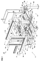
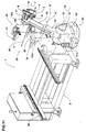
- Fig. 1 is a perspective view of a draw-bending machine according to a first embodiment of the invention;
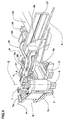
- Fig. 2 is a perspective view of an enlarged portion of the machine seen according to arrow A in Fig. 1;
- Fig. 3 is a perspective view of a first detail to an enlarged scale of the machine portion shown in Fig. 2 before bending of the pipe;
- Fig. 4 shows the same detail as in Fig. 3, after bending of the pipe, seen according to arrow B in Fig. 3;
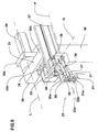
- Fig. 5 is a perspective view of a second detail of the machine in Fig. 1;
- Fig. 6 is a perspective view of the detail in Fig. 4 to an enlarged scale;
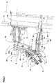
- Fig. 7 is an elevational side view of the machine shown in Fig. 1 during execution of a first bending;
- Fig. 8 is an elevational side view of the machine in Fig. 2 during execution of a second bending;
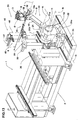
- Fig. 9 is a perspective view of a second embodiment of the draw-bending machine in accordance with the invention, seen according to arrow C in Fig. 1;
- Fig. 10 is a partial elevation and side view of the machine in Fig. 9;
- Fig. 11 is a perspective view of a third embodiment of the draw-bending machine in accordance with the invention, seen according to arrow C in Fig. 1;
- Fig. 12 is a partial elevation and side view of the machine in Fig. 11;
- Fig. 13 is a perspective view of a fourth embodiment of the draw-bending machine in accordance with the invention, seen according to arrow C in Fig. 1;
- Fig. 14 is a partial elevation and side view of the machine in Fig. 13.
- With reference to the drawings, the draw-bending machine in accordance with the invention is identified by
reference numeral 1. - It comprises a
base frame 2 with which abending head 3 is movably in engagement. - The
bending head 3 comprises at least one bending die 4 and onepresser element 5 active on apipe 6 to be bent against the action of said die 4 (Figs. 3 and 4). Saidhead 3 further comprises at least onelocking jaw 7 to press and lockpipe 6 against die 4. Thelocking jaw 7 is rotatably movable relative to thepresser element 5 together with die 4, at a bending axis Z. - For the sake of clarity, by bending axis Z it is intended the axis around which
pipe 6 is bent. - Rotation of the die 4 and
locking jaw 7 relative to thepresser element 5 carried out by appropriate rotation means 4, allows bending ofpipe 6. - In order to release
pipe 6 after bending, both thelocking jaw 7 andpresser element 5 are mounted onrespective slides jaw 7 andpresser element 5 are spaced apart from die 4 and second positions in which the same are disposed close to die 4 to tighten thepipe 6 to be bent. - Advantageously, the
bending head 3 is provided with twodies 4 disposed spaced apart from each other along the bending axis Z and each provided with apresser element 5 and alocking jaw 7. - The
machine 1 further comprises a support andpositioning device 9 for thehead 3 which is linked to the base frame 2 (Figs. 1, 9, 11 and 13). - The support and
positioning device 9 is made up of afirst support arm 10 movably in engagement with thebase frame 2 by appropriate first 11 and second 12 actuating means. - In a first embodiment, clearly shown in Figs. 1, 2, 7 and 8, the
first support arm 10 is moved by the first 11 and second 12 actuating means along a first translation direction X and a second translation direction Y perpendicular to the first one X, respectively. - In particular, the
first support arm 10 is mounted on firstsliding guides 13 oriented along the first translation direction X which is horizontal to the resting surface of thebase frame 2, and formed on afirst slide 14. Thefirst slide 14 is in turn in engagement with second verticalsliding guides 15 oriented along the second translation direction Y and integral with asupport body 16 mounted on thebase frame 2. - The first arm is therefore movable in a vertical plane defined by two translation directions X, Y along which the first 11 and second 12 actuating means are operatively active.
- Consecutively hinged on a
first end 10a of thefirst support arm 10, at a first articulation axis J, is asecond support arm 17. - Advantageously, the
second arm 17 is driven by third actuating means 18 and can take a plurality of angular positions relative to thefirst support arm 10. - In more detail, as clearly shown in Fig. 2, the
second arm 17 has afirst end 17a connected to thefirst support arm 10 and asecond end 17b rotatably linked to thebending head 3 at a second articulation axis K; thebending head 3 is therefore mounted in cantilevered fashion with respect to thesupport body 16. - In addition, fourth actuating means 19 operatively active between the
second arm 17 and bendinghead 3 enables relative positioning between the two elements. - According to the first embodiment shown, the first and second articulation axes J, K are parallel to each other and in addition they are perpendicular to both the first X and second Y translation directions.
- The bending axis Z is then perpendicular to both the articulation axes J, K and therefore said axis Z lies in a vertical plane parallel to the two translation directions X, Y, irrespective of the movements carried out by the
support arms head 3 itself. - Alternatively, in a second embodiment shown in Figs. 9 and 10, the
first support arm 10 is movable relative to thebase frame 2 around a rotation axis I and in a translation direction U coincident with the longitudinal extension of thefirst support arm 10 and perpendicular to the rotation axis I itself. - In particular, the
first arm 10 is mounted on sliding guides, similar to those of the first embodiment and not shown, formed in arotating plate 20. The rotatingplate 20 is in turn hinged on thesupport body 16 mounted on thebase frame 2. - The first actuating means 11 is operatively active along a translation direction U to move the
first support arm 10 on the sliding guides provided inplate 20, whereas the second actuating means 12 is operatively active around the rotation axis I, to rotate therotating plate 20 together with thefirst arm 10. - Advantageously, the rotation axis I is horizontal relative to the resting surface of the
base frame 2, and consequently thefirst support arm 10 is movable in a vertical plane perpendicular to the rotation axis I itself. - As in the first embodiment, the
second support arm 17 is rotatably connected to thefirst end 10a of thefirst arm 10 at the first articulation axis J that in the second embodiment shown is parallel to the rotation axis I. - For details concerning arrangement of the bending
head 3 relative to thesecond support arm 17 reference is to be made to the already described first embodiment. - Thus, the first and second articulation axes J, K are parallel to each other and in addition they are parallel to the rotation axis I.
- Furthermore, the bending axis Z is perpendicular to the rotation axis I and therefore said axis Z lies in a vertical plane perpendicular to the three axes I, J, K, irrespective of the movements carried out by the
support arms head 3. - In a third embodiment, viewed from Figs. 11 and 12, the
first support arm 10 is mounted on anauxiliary arm 21 at afirst end 21a of theauxiliary arm 21 itself; in turn, theauxiliary arm 21 is hinged at itssecond end 21b, opposite to the first one 21a, on a fixedbase 22 placed close to thebase frame 2. Theauxiliary arm 21 together with the first andsecond support arms multi-axis robot arm 23. - In particular, the
first arm 10 is movable relative to theauxiliary arm 21 around a first rotation axis A parallel to the first articulation axis J and theauxiliary arm 21 is hinged on the fixedbase 22 at a second rotation axis B, parallel to the first articulation axis J as well. The first actuating means 11 is operatively active around the first rotation axis A, to rotate thefirst support arm 10 relative to theauxiliary arm 21, whereas the second actuating means 12 is operatively active around the second rotation axis B, to rotate theauxiliary arm 21 relative to the fixedbase 22. Therobot arm 23 is thus able to move axis Z of the bendinghead 3 in a vertical plane perpendicular to the two rotation axes A, B which are horizontal and parallel to each other and to the two articulation axes J, K, irrespective of the movements carried out by thesupport arms auxiliary arm 21 andhead 3. - Finally, in a fourth embodiment shown in Figs. 12 and 13, the
base 22 of therobot arm 23 as described in the third embodiment is slidably mounted on slidingguides 24 that, through anappropriate motor 24a, enable movement thereof along a translation direction C parallel to the ground and perpendicular to the two rotation axes A, B and the two articulation axes J, K. - Thus, in the last-mentioned configuration too, axis Z of the bending
head 3 stays parallel to a vertical plane perpendicular to the four axes A, B, J, K, irrespective of the movements carried out by thesupport arms auxiliary arm 21,base 22 andhead 3. - The bending
machine 1 further comprises (Figs. 5 and 6) a firstgripping unit 25 for thepipe 6 to be bent which has a dual function, i.e. of picking up thepipe 6 from an appropriate feeding device 26 (Figs. 1, 9, 11 and 13) to bring it to an operating space that can be reached by the bendinghead 3, and of supporting the pipe during the bending operation. - The first
gripping unit 25 is formed of twoclamps pipe 6 to be bent at two regions spaced apart from each other and with the longitudinal pipe axis disposed perpendicular to the bending axis Z, therefore in the right position for being engaged between the bending die 4 and lockingjaw 7. - In fact, the
first clamp 27 is aligned with thesecond clamp 28 along a first alignment direction P that, when clamps 27, 28 tightenpipe 6, is coincident with the longitudinal axis of the pipe itself. This first alignment direction P is perpendicular to the bending axis Z or, more specifically, to the plane in which the support andpositioning device 9 shifts the bending axis Z. - In addition the
second clamp 28 is movable along said first direction P, close to or away from thefirst clamp 27, through fifth actuating means 29 shown in Figs. 1 and 2, to enable gripping ofpipe 6 at two positions disposed a varying axial distance from each other. - Each
clamp arms 30, 31 (Figs. 5 and 6), movable between a first position in which they are spaced apart from each other and a second position in which they are close to each other to tighten the interposedpipe 6. - Each
arm end pipe 6 to be tighten. When the twoarms mating cavities 32 form a passage forpipe 6. - The first
gripping unit 25 is therefore able to support apipe 6 made up of two rigid portions connected by a median flexible stretch at appropriate connecting fittings. In fact, eachclamp - In addition,
arms first clamp 27 are provided withgripping ends different radius pipe 6 can be clamped both on its nominal diameter and on the diameter of the connecting fitting. - To alternately align the first or second cavities, 32a or 32b, with the
second clamp 28, thefirst clamp 27 is also movable along a second alignment direction Q perpendicular to the first alignment direction P. - As clearly viewed from Figs. 5 and 6, the
first clamp 27 is mounted on afirst platform 33 movable onfirst rails 34 integral with athird support arm 35 and oriented along the second alignment direction Q. - The
second clamp 28 is mounted on asecond platform 36 slidable on at least onesecond rail 37 integral with thethird arm 35 and oriented along the first alignment direction P. - It is to be pointed out that the two
clamps second clamp 28, as clearly shown in Fig. 6, can be also positioned between theopen ends first clamp 27. - Advantageously, the
third support arm 35 has afirst end 35a to which the firstgripping unit 25 is fastened, and asecond end 35b rotatably linked to theend 38a of a first support column 38 (Fig. 5). - The
third support arm 35 is able to rotate, through appropriate sixth actuating means 39, around a third articulation axis L located at thesecond end 35b, for orientation of the grippingunit 25. - The
first column 38 is in engagement with thirdhorizontal rails 40 of athird platform 41 enabling translation ofcolumn 38 through seventh actuating means 42 along a first movement direction V. - In the first embodiment (Figs. 1, 2, 7 and 8) the first movement direction V is parallel to the first translation direction X; in the second embodiment (Figs. 9 and 10) the first movement direction V is perpendicular to the rotation axis I; finally, in the third embodiment (Figs. 11 and 12) and fourth embodiment (Figs. 13 and 14) said first movement direction V is perpendicular to the two rotation axes A, B.
- The
third platform 41 is in turn in engagement with fourthhorizontal rails 43 integral with thebase frame 2 and extending at right angles to the third horizontal rails 40. Therefore thefirst column 38, through thefourth rails 43 and eighth actuating means 44 (Figs. 1 and 5) dedicated thereto, can also move along a second movement direction W perpendicular to the first movement direction V. - Advantageously, the third articulation axis L is parallel to the first alignment direction P and the second movement direction W so that
pipe 6 picked up from thefeeding device 26 moves always parallel to itself. - Thus, irrespective of the position to which
pipe 6 is moved by the grippingunit 25, said pipe always keeps a correct orientation to enable the bendinghead 3 to reach it. - The draw-bending
machine 1 finally comprises a rotation unit 45 (Figs. 1, 9, 11 and 13) to rotatepipe 6 through 180° and enable the bendinghead 3 to bend both ends of thepipe 6 itself with ease. - The
rotation unit 45 consists of a secondgripping unit 46 mounted on afourth support arm 47 in turn rotatably mounted on a secondfixed support column 48 put close to thebase frame 2. - In particular, like the first
gripping unit 25, the secondgripping unit 46 as well comprises athird clamp 49 in alignment with afourth clamp 50 along a third alignment direction R that, when clamps 49, 50 tightenpipe 6, is coincident with the longitudinal axis of thepipe 6 itself. - In the embodiment shown the second
gripping unit 46 andfourth support arm 47 rotate about a fourth articulation axis M perpendicular to the third alignment direction R. - The second
gripping unit 46 is movable through an angle of 180°, between two opposite positions in which the third alignment direction R and consequently the longitudinal axis ofpipe 6, is parallel to the first alignment direction P. - The first 25 and second 46 gripping units together with the structures connected therewith, therefore constitute the handling and locking means 51 for the
pipes 6 being worked. - After describing the invention mainly from a structural point of view, a pipe bending method being part of the present invention is now set out.
- After arrangement of
pipes 6 to be bent in thefeeding device 26, the firstgripping unit 25 is moved close to thefeeding device 26 and said unit, by means ofclamps pipe 6 up disposing the longitudinal axis of thepipe 6 itself along the first alignment direction P. - Subsequently, through rotation about the third articulation axis L and translation along the first V and second W movement directions, the first
gripping unit 25 bringspipe 6 still parallel to itself into the operating space that can be reached by the bendinghead 3. - The support and
positioning device 9 moves the bendinghead 3 until engagement ofpipe 6 between one of the two bending dies 4, therespective presser element 5 and the lockingjaw 7, the two last-mentioned elements being spaced apart fromdie 4. - During this movement, the
head 3 and related bending axis Z are inclined in a first reference direction Z' selected on the basis of the plane in which the curve must lie. In fact, the bending plane, i.e. the plane in which the elbow shape to be formed onpipe 6 lies, is the plane perpendicular to the bending axis Z. - The locking
jaw 7 andpresser element 5 move close to die 4 to tightenpipe 6, and subsequently thedie 4 and lockingjaw 7 rotate with respect to thepresser element 5 around the bending axis Z to form the curve or bend. - If a second curve is wished to be made in a plane different from the plane in which the first was made, after releasing
pipe 6 from clamping and bringing die 4 back to the starting position, the working cycle involves moving of the bendinghead 3 away frompipe 6, axial sliding of thepipe 6 itself to change the bending region, and subsequent moving of the bendinghead 3 close to the pipe according to a second reference direction Z" different from the first one Z'. - Due to the machine structure, the reference directions Z', Z" according to which axis Z is inclined stay in a plane perpendicular to the first alignment direction P.
- In particular, with reference to the first embodiment shown in Figs. 7 and 8, after the first
gripping unit 25 has movedpipe 6 towards the bendinghead 3 through sliding on the fourth horizontal rails 43 (Fig. 1), in order to move from the position shown in Fig. 7 to that shown in Fig. 8, thefirst support arm 10, lowers along the second vertical translation direction Y for example, and the bendinghead 3 rotates until it gets into alignment with thesecond support arm 17. - In any case it should be noted that, due to the great number of degrees of freedom of the
machine 1, a given relative position between the bendinghead 3 andpipe 6 is not univocally determined. In fact, a given plane of bending with innumerable positions of the movable members of themachine 1 can be obtained onpipe 6. - Practically
pipe 6 during the bending step, can be disposed at any axial position parallel to the first alignment direction P, whereas in the prior art, on the contrary,pipe 6 always keeps a single position in an axial direction. - If a portion of
pipe 6 close to the opposite end is wished to be bent, the handling and locking means 51 is able to rotatepipe 6 through 180°. In particular, after moving apart the bendinghead 3, the firstgripping unit 25 bringspipe 6 close to the secondgripping unit 46 of therotation unit 45. The secondgripping unit 46 graspspipe 6 and, through rotation through 180° around the fourth articulation axis M, turns it over and returns it to the grippingunit 25 to bring the unworked end towards the bendinghead 3. - The invention achieves important advantages.
- It should be first of all pointed out that the draw-bending machine in accordance with the present invention enables pipes made up of two rigid portions connected together by a flexible stretch to be bent in different planes.
- In fact, the particular structure of the first gripping unit allows the two rigid portions of the pipe to be grasped irrespective of the length of the flexible stretch whereas the bending head is able to rotate around the fixed pipe to form curves in any wished and intended plane.
- Therefore, pipe testing in order to check the pipe tightness can be carried out on the assembled pipe still in a rectilinear condition, which will bring about a reduction in time and costs.
- The machine in accordance with the invention therefore enables passage from the assembled components not yet bent to the finished product without being obliged to store bent pipes before assembling. In this way there is no risk of each bent rigid pipe being damaged during storage and subsequent picking up for assembling.
- It should be finally appreciated that the draw-bending machine of the invention enables the same bending head moved by the support and positioning device to be also used to discharge the finished pipe into an unloading area selected each time, or even into a further working station.
Claims (26)
- A draw-bending machine comprising:the support and positioning device (9) of said at least one bending head (3) presenting:a base frame (2);a bending head (3) movably in engagement with the base frame (2) and including at least one bending die (4) rotatable about a bending axis (Z);a support and positioning device (9) of said at least one bending head (3), said support and positioning device (9) being linked to the base frame (2);handling and locking means (51) for a pipe (6) to be bent;the draw-bending machine being characterized in that the handling and locking means (51) for the pipe (6) to be bent comprises a first gripping unit (25) having a first (27) and a second (28) clamps aligned along a first alignment direction (P) to tighten the pipe (6) to be bent at two regions spaced apart from each other.a first support arm (10) movably in engagement with the base frame (2), said first support arm (10) having a first end (10a) and a second end (10b) opposite to the first one (10a);first actuating means (11) of the first support arm (10);second actuating means (12) of the first support arm (10);a second support arm (17) having a first end (17a) hinged on the first end (10a) of the first support arm (10) at a first articulation axis (J) and a second end (17b) hinged on the bending head (3) at a second articulation axis (K);third actuating means (18) of the second support arm (17) around the first articulation axis (J);fourth actuating means (19) of the bending head (3) around the second articulation axis (K);
- A draw-bending machine as claimed in claim 1, characterized in that the first support arm (10) is movable relative to the base frame (2) along a first translation direction (X) and along a second translation direction (Y) perpendicular to the first one (X).
- A draw-bending machine as claimed in claim 2, characterized in that the first actuating means (11) of the first support arm (10) is operatively active along the first translation direction (X) and the second actuating means (12) of the first support arm (10) is operatively active along the second translation direction (Y).
- A draw-bending machine as claimed in claim 2, characterized in that the first translation direction (X) is horizontal to the resting surface of the base frame (2) and the second translation direction (Y) is vertical to the resting surface of the base frame (2).
- A draw-bending machine as claimed in claim 1, characterized in that the second articulation axis (K) is parallel to the first articulation axis (J).
- A draw-bending machine as claimed in claim 2, characterized in that said first (J) and second (K) articulation axes are perpendicular to both the first (X) and second (Y) translation directions.
- A draw-bending machine as claimed in claim 2, characterized in that the bending axis (Z) lies in a plane parallel to both the first translation axis (X) and the second translation axis (Y).
- A draw-bending machine as claimed in claim 1, characterized in that the first support arm (10) is movable relative to the base frame (2) about a rotation axis (I) and along a translation direction (U) perpendicular to the rotation axis (I).
- A draw-bending machine as claimed in claim 8, characterized in that the translation direction (U) is coincident with the longitudinal extension of the first support arm (10).
- A draw-bending machine as claimed in claim 8 or 9, characterized in that the first actuating means (11) of the first support arm (10) is operatively active along the translation direction (U) and the second actuating means (12) of the first support arm (10) is operatively active around the rotation axis (I).
- A draw-bending machine as claimed in claim 8, characterized in that the rotation axis (I) is horizontal to the resting surface of the base frame (2).
- A draw-bending machine as claimed in claim 8, characterized in that said first (J) and second (K) articulation axes are parallel to the rotation axis (I).
- A draw-bending machine as claimed in claim 8, characterized in that the bending axis (Z) lies in a plane perpendicular to the rotation axis (I).
- A draw-bending machine as claimed in claim 1, characterized in that it further comprises:an auxiliary arm (21) hinged on the first support arm (10) at a first rotation axis (A);a fixed base (22) placed close to the base frame (2); the auxiliary arm (21) being in addition hinged on the fixed base (22) at a second rotation axis (B).
- A draw-bending machine as claimed in claim 14, characterized in that the first actuating means (11) is operatively active around the first rotation axis (A) to rotate the first support arm (10) relative to the auxiliary arm (21), and the second actuating means (12) is operatively active around the second rotation axis (B) to rotate the auxiliary arm (21) relative to the fixed base (22).
- A draw-bending machine as claimed in claim 14, characterized in that the first rotation axis (A) and second rotation axis (B) are horizontal to the resting surface of the base frame (2) and parallel to each other.
- A draw-bending machine as claimed in claim 14, characterized in that the first rotation axis (A), second rotation axis (B), first articulation axis (J) and second articulation axis (K) are parallel to each other.
- A draw-bending machine as claimed in claim 14, characterized in that the bending axis (Z) lies in a plane perpendicular to the first rotation axis (A) and the second rotation axis (B).
- A draw-bending machine as claimed in claim 14, characterized in that it further comprises sliding guides (24) oriented along a translation direction (C) horizontal to the resting surface of the base frame (2) and perpendicular to the first rotation axis (A), second rotation axis (B), first articulation axis (J) and second articulation axis (K).
- A draw-bending machine as claimed in claim 1, characterized in that the bending head further comprises:at least one presser element (5) active on said pipe (6) against the action of said die (4);at least one locking jaw (7) rotatably movable at the bending axis (Z) together with the die (4), said locking jaw (7) being movable between a first position in which it is spaced apart from the die (4), and a second position in which it is close to the die (4) to tighten the pipe (6) to be bent.
- A draw-bending machine as claimed in claim 1, characterized in that the first alignment direction (P) is perpendicular to the bending axis (Z).
- A draw-bending machine as claimed in claim 1, characterized in that the second clamp (28) is movable close to or away from the first clamp (279 along said first alignment direction (P).
- A draw-bending machine as claimed in claim 1, characterized in that the handling and locking means (51) further comprises:a first support column (38) mounted on the base frame (2) and provided with an end (38a);a third support arm (35) having a first end (35a) and a second end (35b) opposite to the first one; the first gripping unit (25) being fastened to the first end (35a) of the third support arm (35); the second end (35b) of the third support arm (35) being rotatably linked to the end (38a) of the first column (38) at a third articulation axis (L);sixth actuating means (39) of the third arm (35) around the third articulation axis (L).
- A draw-bending machine as claimed in claim 23, characterized in that the first support column (38) is movable along a first movement direction (V) and along a second movement direction (W) perpendicular to the first movement direction (V).
- A method of bending pipes comprising the following steps:characterized in that the step of positioning the pipe (6) to be bent involves the steps of:positioning a pipe (6) to be bent within an operating space to be reached by a bending head (3) defining a bending axis (Z); the longitudinal axis of said pipe (6) being disposed along a first alignment direction (P); the bending axis (Z) lying in a plane perpendicular to the first alignment direction (P);shifting the bending head (3) a first time to engage the pipe (6) to be bent;inclining the bending axis (Z) in a first reference direction (Z') to bend the pipe (6) in a plane perpendicular to said first reference direction (Z');bending the pipe (6) around the bending axis (Z);moving the head (3) away from the pipe (6);axially shifting the pipe (6) along the first alignment direction (P) to change the bending region on said pipe (6);shifting the bending head (3) at least a second time to engage the pipe (6) to be bent;inclining the bending axis (Z) at least in a second reference direction (Z") distinct from the first one (Z') to bend the pipe (6) in a plane perpendicular to said second reference direction (Z');bending the pipe (6) around the bending axis (Z);adjusting the mutual distance of a first clamp (27) and of a second clamp (28) of a first gripping unit (25), said first clamp (27) and second clamp (28) being aligned along the first alignment direction (P);gripping the pipe (6) to be bent with each clamp (27, 28) at two positions disposed at varying axial distance from each other, in order to tighten the pipe (6) at two regions spaced apart from each other;moving the pipe (6) gripped by the gripping unit (25) within the operating space.
- A method of bending pipes comprising the following steps:characterized in that the step of shifting the bending head (3) a first time involves the step of:positioning a pipe (6) to be bent within an operating space to be reached by a bending head (3) defining a bending axis (Z); the longitudinal axis of said pipe (6) being disposed along a first alignment direction (P); the bending axis (Z) lying in a plane perpendicular to the first alignment direction (P);shifting the bending head (3) a first time to engage the pipe (6) to be bent;bending the pipe (6) around the bending axis (Z);moving the head (3) away from the pipe (6);axially shifting the pipe (6) along the first alignment direction (P) to change the bending region on said pipe (6);shifting the bending head (3) at least a second time to engage the pipe (6) to be bent;bending the pipe (6) around the bending axis (Z);inclining the bending axis (Z) in a first reference direction (Z') to bend the pipe (6) in a plane perpendicular to said first reference direction (Z'); and in that the step of shifting the bending head (3) at least a second time comprises the step of:inclining the bending axis (Z) at least in a second reference direction (Z") distinct from the first one (Z') to bend the pipe (6) in a plane perpendicular-to said second reference direction (Z').
Priority Applications (5)
| Application Number | Priority Date | Filing Date | Title |
|---|---|---|---|
| DE60100147T DE60100147T2 (en) | 2001-10-02 | 2001-10-02 | Draw bending device and method |
| ES01830619T ES2194827T3 (en) | 2001-10-02 | 2001-10-02 | MACHINE FOR CURVING WITH TRACTION. |
| EP01830619A EP1291094B1 (en) | 2001-10-02 | 2001-10-02 | Draw-bending machine |
| US10/246,614 US6694794B2 (en) | 2001-10-02 | 2002-09-17 | Draw-bending machine |
| CA002411795A CA2411795A1 (en) | 2001-10-02 | 2002-11-13 | Draw-bending machine |
Applications Claiming Priority (2)
| Application Number | Priority Date | Filing Date | Title |
|---|---|---|---|
| EP01830619A EP1291094B1 (en) | 2001-10-02 | 2001-10-02 | Draw-bending machine |
| CA002411795A CA2411795A1 (en) | 2001-10-02 | 2002-11-13 | Draw-bending machine |
Publications (2)
| Publication Number | Publication Date |
|---|---|
| EP1291094A1 true EP1291094A1 (en) | 2003-03-12 |
| EP1291094B1 EP1291094B1 (en) | 2003-03-26 |
Family
ID=32963070
Family Applications (1)
| Application Number | Title | Priority Date | Filing Date |
|---|---|---|---|
| EP01830619A Expired - Lifetime EP1291094B1 (en) | 2001-10-02 | 2001-10-02 | Draw-bending machine |
Country Status (5)
| Country | Link |
|---|---|
| US (1) | US6694794B2 (en) |
| EP (1) | EP1291094B1 (en) |
| CA (1) | CA2411795A1 (en) |
| DE (1) | DE60100147T2 (en) |
| ES (1) | ES2194827T3 (en) |
Cited By (7)
| Publication number | Priority date | Publication date | Assignee | Title |
|---|---|---|---|---|
| EP1350578A1 (en) * | 2002-04-03 | 2003-10-08 | Trumpf Rohrtechnik GmbH + Co. KG | Machine for bending bar and/or rod-like workpieces, in particular tubes |
| FR2859653A1 (en) * | 2003-09-12 | 2005-03-18 | Silfax Sa | ORBITAL MACHINE FOR BENDING TUBES |
| DE102013200850A1 (en) * | 2013-01-21 | 2014-07-24 | Wafios Aktiengesellschaft | Device for bending strand-shaped workpieces |
| CN104259342A (en) * | 2014-09-11 | 2015-01-07 | 建科机械(天津)股份有限公司 | Locking mechanism on steel bar bending machine |
| EP3046234A1 (en) * | 2015-01-14 | 2016-07-20 | A.S.EN. Ansaldo Sviluppo Energia S.r.l. | Method and apparatus for shaping at least one alternator bar |
| CN109549699A (en) * | 2018-12-04 | 2019-04-02 | 中南大学湘雅医院 | The automatic moulding mechanism of the medical internal fixation plate of camber line Type Titanium Alloy |
| IT201900006821A1 (en) * | 2019-05-14 | 2020-11-14 | Star Tech S R L | Machine for bending elongated elements such as bars, pipes and the like and method of operation of this machine |
Families Citing this family (21)
| Publication number | Priority date | Publication date | Assignee | Title |
|---|---|---|---|---|
| US7047785B2 (en) * | 2002-06-28 | 2006-05-23 | Oscam Spa | Installation for processing metal bars with improved means for transferring the bars, and method provided thereby |
| PL1651367T3 (en) * | 2003-08-05 | 2007-09-28 | Rosenberger Ag | Method for bending workpieces |
| CN100391641C (en) * | 2006-03-20 | 2008-06-04 | 上海圣诺机床有限公司 | Detachable combined rear positioning structure |
| US7254972B1 (en) * | 2006-06-28 | 2007-08-14 | Chia Sheng Machinery Co., Ltd. | Moving mold mechanism of a pipe bending machine |
| DE502007005038D1 (en) | 2007-02-07 | 2010-10-28 | Wafios Ag | bending machine |
| EP1970139B1 (en) | 2007-03-14 | 2009-04-29 | WAFIOS Aktiengesellschaft | Gripper device for gripping and retaining long workpieces, in particular for bending machines |
| AT505657B1 (en) * | 2007-08-16 | 2009-03-15 | Hammerschmid Maschb Gmbh | DEVICE AND METHOD FOR BENDING SEMI-FINISHED PRODUCTS |
| DE202007015831U1 (en) * | 2007-11-13 | 2009-03-26 | Wilhelm Karmann Gmbh | Workstation for machining a workpiece, in particular a linkage element of a top linkage of a convertible vehicle |
| EP2177287B1 (en) | 2008-10-17 | 2011-11-30 | WAFIOS Aktiengesellschaft | Support split assembly for gliding side supports of rod and tube-shape workpieces on bending machines |
| JP5405878B2 (en) * | 2009-04-08 | 2014-02-05 | 株式会社オプトン | Bending machine |
| JP5330064B2 (en) * | 2009-04-08 | 2013-10-30 | 株式会社オプトン | Bending machine |
| JP5405879B2 (en) * | 2009-04-08 | 2014-02-05 | 株式会社オプトン | Bending machine |
| IT1401361B1 (en) * | 2010-06-10 | 2013-07-18 | Blm Spa | TUBE BENDER MACHINE WITH AUTOMATIC LOADING SYSTEM AND METHOD FOR THE AUTOMATIC LOADING OF TUBES ON THE BENDING HEAD OF A TUBE BENDER. |
| JP6101454B2 (en) * | 2012-09-04 | 2017-03-22 | 株式会社アマダホールディングス | Work processing apparatus and method of moving a mold in the work processing apparatus |
| JP1539124S (en) * | 2014-08-15 | 2015-11-30 | ||
| USD755861S1 (en) * | 2014-08-15 | 2016-05-10 | Trumpf Gmbh + Co. Kg | Bending machine |
| AT516371B1 (en) * | 2014-12-02 | 2016-05-15 | Stonawski Rudolf | Device for bending a profile workpiece |
| CN104858272B (en) * | 2015-05-11 | 2016-08-10 | 武汉思瑞法机器人制造有限公司 | Pipeline bender |
| IT201600119591A1 (en) * | 2016-11-25 | 2018-05-25 | Crippa Spa | Machine for bending filiform material such as a pipe with a system for the simultaneous loading of the pipe to be bent and discharge of the curved pipe |
| CN107127231A (en) * | 2017-06-05 | 2017-09-05 | 肇庆市端州区麒诺机械科技有限公司 | Pipeline bender |
| IT202100011660A1 (en) * | 2021-05-06 | 2022-11-06 | Schnell Spa | METHOD AND EQUIPMENT FOR BENDING BARS |
Citations (6)
| Publication number | Priority date | Publication date | Assignee | Title |
|---|---|---|---|---|
| US3299681A (en) * | 1960-03-22 | 1967-01-24 | Baldwin Lima Hamilton Corp | Program controlled tube bender |
| DE3620151A1 (en) * | 1985-06-19 | 1987-02-26 | Asea Ab | Method and robotic device for bending bar-shaped stock or workpieces |
| GB2187666A (en) * | 1986-03-15 | 1987-09-16 | Pressbend Ltd | Pipe bending apparatus |
| US4945747A (en) * | 1989-05-11 | 1990-08-07 | Chuo Electric Manufacturing Co., Ltd. | Apparatus for bending elongated materials in any direction |
| EP0538207A2 (en) * | 1991-10-16 | 1993-04-21 | FABBRICA MACCHINE CURVATUBI CRIPPA AGOSTINO S.p.A. | Multi-function pipe bending machine |
| EP1065015A1 (en) * | 1999-06-21 | 2001-01-03 | TI Group Automotive Systems | Apparatus for bending elongate metallic objects such as tubes |
Family Cites Families (12)
| Publication number | Priority date | Publication date | Assignee | Title |
|---|---|---|---|---|
| JPH02299724A (en) * | 1989-05-11 | 1990-12-12 | Chuo Electric Mfg Co Ltd | Bending device |
| IT1236462B (en) * | 1989-12-29 | 1993-03-09 | Fabro Giorgio Del | SATELLITE BENDING GROUP |
| JPH0565440U (en) * | 1992-02-03 | 1993-08-31 | 安川商事株式会社 | Wire bending equipment |
| US5825759A (en) * | 1994-10-26 | 1998-10-20 | Telefonaktiebolaget Lm Ericsson | Distributing network services and resources in a mobile communications network |
| IT1290141B1 (en) * | 1997-03-21 | 1998-10-19 | Blm Spa | MACHINE TO CURVE FILIFORM MATERIALS SUCH AS BAR TUBES OR PROFILES |
| US6098108A (en) * | 1997-07-02 | 2000-08-01 | Sitara Networks, Inc. | Distributed directory for enhanced network communication |
| US6338117B1 (en) * | 1998-08-28 | 2002-01-08 | International Business Machines Corporation | System and method for coordinated hierarchical caching and cache replacement |
| US20020073167A1 (en) * | 1999-12-08 | 2002-06-13 | Powell Kyle E. | Internet content delivery acceleration system employing a hybrid content selection scheme |
| US6505200B1 (en) * | 2000-07-06 | 2003-01-07 | International Business Machines Corporation | Application-independent data synchronization technique |
| WO2002069172A1 (en) * | 2001-02-22 | 2002-09-06 | Didera, Inc. | Systems and methods for managing distributed database resources |
| US6820116B1 (en) * | 2001-12-21 | 2004-11-16 | Nokia Corporation | Mobile browsing booster system |
| US20040009815A1 (en) * | 2002-06-26 | 2004-01-15 | Zotto Banjamin O. | Managing access to content |
-
2001
- 2001-10-02 EP EP01830619A patent/EP1291094B1/en not_active Expired - Lifetime
- 2001-10-02 ES ES01830619T patent/ES2194827T3/en not_active Expired - Lifetime
- 2001-10-02 DE DE60100147T patent/DE60100147T2/en not_active Expired - Fee Related
-
2002
- 2002-09-17 US US10/246,614 patent/US6694794B2/en not_active Expired - Fee Related
- 2002-11-13 CA CA002411795A patent/CA2411795A1/en not_active Abandoned
Patent Citations (6)
| Publication number | Priority date | Publication date | Assignee | Title |
|---|---|---|---|---|
| US3299681A (en) * | 1960-03-22 | 1967-01-24 | Baldwin Lima Hamilton Corp | Program controlled tube bender |
| DE3620151A1 (en) * | 1985-06-19 | 1987-02-26 | Asea Ab | Method and robotic device for bending bar-shaped stock or workpieces |
| GB2187666A (en) * | 1986-03-15 | 1987-09-16 | Pressbend Ltd | Pipe bending apparatus |
| US4945747A (en) * | 1989-05-11 | 1990-08-07 | Chuo Electric Manufacturing Co., Ltd. | Apparatus for bending elongated materials in any direction |
| EP0538207A2 (en) * | 1991-10-16 | 1993-04-21 | FABBRICA MACCHINE CURVATUBI CRIPPA AGOSTINO S.p.A. | Multi-function pipe bending machine |
| EP1065015A1 (en) * | 1999-06-21 | 2001-01-03 | TI Group Automotive Systems | Apparatus for bending elongate metallic objects such as tubes |
Cited By (10)
| Publication number | Priority date | Publication date | Assignee | Title |
|---|---|---|---|---|
| EP1350578A1 (en) * | 2002-04-03 | 2003-10-08 | Trumpf Rohrtechnik GmbH + Co. KG | Machine for bending bar and/or rod-like workpieces, in particular tubes |
| FR2859653A1 (en) * | 2003-09-12 | 2005-03-18 | Silfax Sa | ORBITAL MACHINE FOR BENDING TUBES |
| US7093475B2 (en) | 2003-09-12 | 2006-08-22 | Silfax | Orbital machine for bending tubes |
| DE102013200850A1 (en) * | 2013-01-21 | 2014-07-24 | Wafios Aktiengesellschaft | Device for bending strand-shaped workpieces |
| DE102013200850B4 (en) * | 2013-01-21 | 2015-01-22 | Wafios Aktiengesellschaft | Device for bending strand-shaped workpieces |
| CN104259342A (en) * | 2014-09-11 | 2015-01-07 | 建科机械(天津)股份有限公司 | Locking mechanism on steel bar bending machine |
| EP3046234A1 (en) * | 2015-01-14 | 2016-07-20 | A.S.EN. Ansaldo Sviluppo Energia S.r.l. | Method and apparatus for shaping at least one alternator bar |
| CN109549699A (en) * | 2018-12-04 | 2019-04-02 | 中南大学湘雅医院 | The automatic moulding mechanism of the medical internal fixation plate of camber line Type Titanium Alloy |
| CN109549699B (en) * | 2018-12-04 | 2021-05-25 | 中南大学湘雅医院 | Automatic moulding mechanism of medical interior fixed plate of pitch arc type titanium alloy |
| IT201900006821A1 (en) * | 2019-05-14 | 2020-11-14 | Star Tech S R L | Machine for bending elongated elements such as bars, pipes and the like and method of operation of this machine |
Also Published As
| Publication number | Publication date |
|---|---|
| US6694794B2 (en) | 2004-02-24 |
| CA2411795A1 (en) | 2004-05-13 |
| ES2194827T3 (en) | 2003-12-01 |
| EP1291094B1 (en) | 2003-03-26 |
| US20030061853A1 (en) | 2003-04-03 |
| DE60100147D1 (en) | 2003-05-22 |
| DE60100147T2 (en) | 2004-01-29 |
Similar Documents
| Publication | Publication Date | Title |
|---|---|---|
| EP1291094B1 (en) | Draw-bending machine | |
| US7104100B2 (en) | Bending device for tube | |
| EP0950443A1 (en) | Tube bender loader and unloader | |
| US20050241356A1 (en) | Bending device with cutting mechanism | |
| US3431759A (en) | Forming apparatus | |
| KR100818840B1 (en) | Apparatus for bending and working long materials | |
| JPS59183938A (en) | Machine for bending cable material | |
| US8337137B2 (en) | Transfer module for transferring parts between work stations | |
| KR101849308B1 (en) | Tube bending machine with an automatic loading system and method for automatic loading of tubes on the bending head of a tube bending machine | |
| CN113453819B (en) | Method and device for automatically switching tool system | |
| CN109500592A (en) | A kind of slotting bending machine | |
| JP2648369B2 (en) | Method and apparatus for forming barrel-shaped coil spring | |
| US7076984B2 (en) | Bending machine and tube support and drive device thereof | |
| WO2023112070A1 (en) | Apparatus and method for bending bars | |
| CN210616510U (en) | Automatic clamping and moving device for feeding and discharging of bent pipe | |
| CN112718978B (en) | Pipe fitting rotating clamp holder and robot pipe bending workstation | |
| CN215378705U (en) | Shaping equipment for outgoing line of round wire stator | |
| CN112453134B (en) | Pipe fitting rotating clamp holder and robot pipe bending workstation comprising same | |
| JPH0513011B2 (en) | ||
| CN113241906A (en) | Shaping equipment for outgoing line of round wire stator | |
| US4683649A (en) | Device for assembling return bend to coil | |
| US4747208A (en) | Device for assembling return bend to coil | |
| CN219986674U (en) | Pipe fitting welding tool | |
| CN212351090U (en) | Intelligent dropper pre-assembly production line | |
| CN216632150U (en) | Pipe bending equipment |
Legal Events
| Date | Code | Title | Description |
|---|---|---|---|
| GRAH | Despatch of communication of intention to grant a patent |
Free format text: ORIGINAL CODE: EPIDOS IGRA |
|
| GRAH | Despatch of communication of intention to grant a patent |
Free format text: ORIGINAL CODE: EPIDOS IGRA |
|
| PUAI | Public reference made under article 153(3) epc to a published international application that has entered the european phase |
Free format text: ORIGINAL CODE: 0009012 |
|
| GRAA | (expected) grant |
Free format text: ORIGINAL CODE: 0009210 |
|
| 17P | Request for examination filed |
Effective date: 20020425 |
|
| AK | Designated contracting states |
Kind code of ref document: A1 Designated state(s): AT BE CH CY DE DK ES FI FR GB GR IE IT LI LU MC NL PT SE TR |
|
| AX | Request for extension of the european patent |
Extension state: AL LT LV MK RO SI |
|
| AK | Designated contracting states |
Designated state(s): DE ES FR GB IT |
|
| REG | Reference to a national code |
Ref country code: GB Ref legal event code: FG4D |
|
| REG | Reference to a national code |
Ref country code: IE Ref legal event code: FG4D |
|
| REF | Corresponds to: |
Ref document number: 60100147 Country of ref document: DE Date of ref document: 20030522 Kind code of ref document: P |
|
| LTIE | Lt: invalidation of european patent or patent extension |
Effective date: 20030326 |
|
| AKX | Designation fees paid |
Designated state(s): DE ES FR GB IT |
|
| ET | Fr: translation filed | ||
| PLBE | No opposition filed within time limit |
Free format text: ORIGINAL CODE: 0009261 |
|
| STAA | Information on the status of an ep patent application or granted ep patent |
Free format text: STATUS: NO OPPOSITION FILED WITHIN TIME LIMIT |
|
| 26N | No opposition filed |
Effective date: 20031230 |
|
| REG | Reference to a national code |
Ref country code: IE Ref legal event code: MM4A |
|
| PGFP | Annual fee paid to national office [announced via postgrant information from national office to epo] |
Ref country code: GB Payment date: 20050928 Year of fee payment: 5 |
|
| PGFP | Annual fee paid to national office [announced via postgrant information from national office to epo] |
Ref country code: DE Payment date: 20050929 Year of fee payment: 5 |
|
| PGFP | Annual fee paid to national office [announced via postgrant information from national office to epo] |
Ref country code: FR Payment date: 20051010 Year of fee payment: 5 |
|
| PGFP | Annual fee paid to national office [announced via postgrant information from national office to epo] |
Ref country code: ES Payment date: 20051129 Year of fee payment: 5 |
|
| PGFP | Annual fee paid to national office [announced via postgrant information from national office to epo] |
Ref country code: IT Payment date: 20061031 Year of fee payment: 6 |
|
| PG25 | Lapsed in a contracting state [announced via postgrant information from national office to epo] |
Ref country code: DE Free format text: LAPSE BECAUSE OF NON-PAYMENT OF DUE FEES Effective date: 20070501 |
|
| GBPC | Gb: european patent ceased through non-payment of renewal fee |
Effective date: 20061002 |
|
| REG | Reference to a national code |
Ref country code: FR Ref legal event code: ST Effective date: 20070629 |
|
| PG25 | Lapsed in a contracting state [announced via postgrant information from national office to epo] |
Ref country code: GB Free format text: LAPSE BECAUSE OF NON-PAYMENT OF DUE FEES Effective date: 20061002 |
|
| REG | Reference to a national code |
Ref country code: ES Ref legal event code: FD2A Effective date: 20061003 |
|
| PG25 | Lapsed in a contracting state [announced via postgrant information from national office to epo] |
Ref country code: ES Free format text: LAPSE BECAUSE OF NON-PAYMENT OF DUE FEES Effective date: 20061003 Ref country code: FR Free format text: LAPSE BECAUSE OF NON-PAYMENT OF DUE FEES Effective date: 20061031 |
|
| PG25 | Lapsed in a contracting state [announced via postgrant information from national office to epo] |
Ref country code: IT Free format text: LAPSE BECAUSE OF NON-PAYMENT OF DUE FEES Effective date: 20071002 |