EP1090696B2 - Chain traction device for continuous drawing - Google Patents
Chain traction device for continuous drawing Download PDFInfo
- Publication number
- EP1090696B2 EP1090696B2 EP00120496A EP00120496A EP1090696B2 EP 1090696 B2 EP1090696 B2 EP 1090696B2 EP 00120496 A EP00120496 A EP 00120496A EP 00120496 A EP00120496 A EP 00120496A EP 1090696 B2 EP1090696 B2 EP 1090696B2
- Authority
- EP
- European Patent Office
- Prior art keywords
- chain
- guide
- accordance
- drawing machine
- rollers
- Prior art date
- Legal status (The legal status is an assumption and is not a legal conclusion. Google has not performed a legal analysis and makes no representation as to the accuracy of the status listed.)
- Expired - Lifetime
Links
Images


Classifications
-
- B—PERFORMING OPERATIONS; TRANSPORTING
- B21—MECHANICAL METAL-WORKING WITHOUT ESSENTIALLY REMOVING MATERIAL; PUNCHING METAL
- B21C—MANUFACTURE OF METAL SHEETS, WIRE, RODS, TUBES OR PROFILES, OTHERWISE THAN BY ROLLING; AUXILIARY OPERATIONS USED IN CONNECTION WITH METAL-WORKING WITHOUT ESSENTIALLY REMOVING MATERIAL
- B21C1/00—Manufacture of metal sheets, metal wire, metal rods, metal tubes by drawing
- B21C1/16—Metal drawing by machines or apparatus in which the drawing action is effected by other means than drums, e.g. by a longitudinally-moved carriage pulling or pushing the work or stock for making metal sheets, bars, or tubes
- B21C1/27—Carriages; Drives
- B21C1/30—Drives, e.g. carriage-traversing mechanisms; Driving elements, e.g. drawing chains; Controlling the drive
Definitions
- the invention relates to a chain drawing machine for the continuous drawing of particular rod and tubular drawn material according to the preamble of claim 1, in particular a chain drawing machine with at least two, a common pull track assigned drive chains, each having interconnected tension members and the laterally provided by the tension members means drivable are, wherein the tension members are provided on one side with a pressable to the pulling material clamping jaw and on another side with a sliding surface with which the tension members are supported by rotating, load-bearing idler rollers on a rigid roller guide associated with each drive chain.
- the EP 0 548 723 B2 shows a generic chain drawing machine.
- the tension members of the drive chains have on their back, ie the side facing away from the jaws on a sliding surface, which runs like a rolling bearing on a mitbewegte, guided on a fixed, rigid roller guide chain of idler rollers.
- the clamping force is transmitted by means of the idler rollers directly from the jaws on the sliding surfaces on the roller guide.
- the idler rollers are centered, with all the sliding surfaces of the tension members arranged in series a single, the rigid roller guide opposite and the same width as the idler rollers and the roller guide width extending sliding surface.
- the individual tension members are connected to each other via bolts and have a complicated arrangement of other follower rollers and locking plates whose geometrical dimensions are coordinated.
- the object of the invention is to provide an improved chain drawing machine, which is simple and allows high clamping forces.
- the idler rollers interact with the sliding surface and / or the roller guide via a shared contact surface and are guided at the height of the contact surface division only by guides which follow the rollers.
- a complex guide device on the sliding surface and / or the roller guide need not be provided, which significantly reduces the cost of the frame.
- a maintenance of the machine is easier because a fixed guide or with the trailing members follower guide is very difficult to access.
- roller guides for the drive chains are divided by means of at least one relief recess in guideways in a first alternative.
- the relief recess may extend substantially along the pull section. Since the roller guides, on which the idler rollers roll, are subject to tolerances and in particular are never completely flat, the idler rollers can adapt better to the roller guide due to the relief recess, so that the effective load-bearing force line increases.
- the sliding surface of the tension members is divided by means of at least one relief recess in slideways.
- the idler rollers themselves are designed so that they are slightly articulated, based on the total width of all guideways and slideways, so that they can adapt to existing tolerances in the guideways and slideways.
- the follower rollers extend over at least two guideways, preferably so that in each case a follower roller extends over all guideways.
- the idler rollers particularly advantageously have a circumferential taper assigned to each relief recess.
- the follower rollers experience deliberate weakening or minimizing of their diameter, so that over the width of the idler rollers a resilient adaptation or elastic bending to compensate for the tolerances within the guideways and sliding surfaces can take place.
- the idler rollers consist of parallel guided roller sets, wherein each guideway and / or slideway is associated with a roller set.
- the mechanical effort for the leadership of the idler rollers or roller sets is reduced when the roller sets are then connected to each other via roller cages, especially when the roller sets are designed as chains.
- the guideways and slideways should be uniform and / or opposite each other with the same width. Furthermore, it is advantageous if at least one relief recess divides the roller guide and / or the sliding surface in the middle. In a particularly preferred embodiment, two guideways and / or two slideways are provided.
- the tension members may be connected by means of a connecting bolt, on both sides of the tension members on the connecting pin rollers and / or pull pieces are arranged.
- a uniform application of force and force distribution is favored when the jaws and the sliding surfaces are arranged on opposite, mutually parallel sides of the tension members, wherein the clamping jaws and the sliding surfaces or slideways can be integrally integrated into the tension members.
- the follower rollers are formed at least from two sub-rollers, which are mounted on a common axis.
- This arrangement is particularly inexpensive, since it can be realized with standard components and still shows the same advantages as the arrangements described above.
- a spacer for example a sleeve arranged on the axis, is provided between the partial rollers.
- the follower rollers are connected together to form a chain. Since the tabs of the chain partially overlap, a bending of the chain in the lateral direction is limited. This results in a simple way an external guide of the idler rollers or sub-rollers. This outer guide can absorb laterally acting executives.
- inner guide elements can receive laterally acting guiding forces, wherein they run along with the rollers and are arranged at the level of the contact surface division and thereby do not come into effective contact with fixed guide elements in the lateral direction.
- the fact that the inner guide elements can independently absorb management forces, can be dispensed with internal components, which would have to be executed in the form of fixed guide elements.
- the laterally acting guiding forces are understood to be forces which have a force component which acts on an orthogonal plane which is imaginary in the longitudinal direction of the guiding surface.
- the inner guide elements are advantageously arranged parallel to the sliding surface and between the sliding surface and the guide surface.
- these inner guide elements are also arranged. As a result, can be dispensed with fixed side components for guiding the idler rollers.
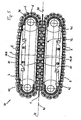
- Fig. 1 shows in principle the drive chain guide a chain drawing machine, not shown substantially.
- the designated 1 drawn material is clamped between the jaws 2 an endlessly rotating upper drive chain 3 and an endlessly circulating lower drive chain 4.
- the drive chains 3,4 each consist of a plurality of identical to each other trained tension members 5A, 5B, which are interconnected by means of a connecting pin 6, wherein the jaws 2 on the outer side 5 'of the tension members 5A, 5B, based on the orbit of the drive chains 3.4 , are arranged.
- nuts 7 the connection of the tension members 5A, 5B is secured.
- the chain drawing machine spaced from each other, here sprockets, not shown, whose teeth interact, for example, with the connecting pin 6 directly or via pull pieces 5A.
- sprockets for each drive chain 3,4 two spaced sprockets are provided, between which the drive chains 3,4 through and circulate. In this way, a drive is ensured laterally of the tension members.
- the drive chains 3, 4 are supported along a drawing path, on which the clamping jaws 2 are pressed against the drawn material 1, via follower rollers 8 on a rigid guide surface designated overall by 9 and arranged on the machine frame 10.
- the guide surface 9 has centrally a relief recess 11 which divides the guide surface 9 into a first guide track 9A and a second guide track 9B.
- the continuous follower roller 8 which preferably extends at least over the width of both guideways 9A, 9B or both slides 13A, 13B, a circumferential taper 15 in the form of a Specially adapted groove or the like.
- the circumferential taper 15 ensures that the follower roller 8 can flex elastically and thus can optimally rest with its remaining sections 8A, 8B on the guideways 9A, 9B and slide tracks 13A, 13B, so that the entire width of the Sections 8A, 8B in the support of the tension members 5A, 5B is available as a support surface.
- the follower rollers 8 may be single roles in special guides or, as shown, be designed as connected with tabs 16 roller chains. Since the tabs 16 mutually partially overlap in the immediate vicinity of the connecting pin 6 and thereby allow only a limited lateral bending of the roller chain, thus the tabs can partially compensate laterally acting executives. The tabs 16 take the task of a direct outer leadership true.
- the special guides may be formed as inner guide elements 31. These inner guide elements can hereby absorb laterally acting guiding forces and thus hold the follower rollers 8 in the region of the guide tracks 9. As a result, it is possible to dispense with fixed guide elements which are arranged between the sliding surface 13 and the guide surface 9.
- Fig. 2 An alternative embodiment is shown in half only. Identical components are provided with the same reference numerals.
- the difference to the embodiment according to Fig. 1 lies in the structure of the follower rollers 18.
- the follower rollers 18 here consist of two roller sets 18A, 18B, thus divided over the guide surface or sliding surface individual follower rollers; the first roller set 18A is associated with the guide and slide tracks 9A, 13A, the second roller set 18B is associated with the guide and slide tracks 9B, 13B.
- the roller assemblies 18A, 18B may be interconnected, eg, via roller cages (not shown), and / or the idlers 18 of the respective roller assemblies may be interconnected via tabs 16, as shown.
- the tabs 16 may represent a direct outer leadership, since the tabs can absorb laterally acting executives.
- the inner guide elements 31 can receive laterally acting guiding forces, so that fixed guide elements are no longer needed even in this alternative embodiment for a perfect function in the region of the drawing path of the chain drawing machine.
- two sub-rollers 28A, 28B are provided for the follower rollers 28, which are arranged on an axis 29.
- a spacer 30 between the sub-rollers 28A, 28B is arranged on the axis 29, which serves to guide the idler rollers 28.
- the relief recess is dispensed with, and the adaptability or flexibility of the follower rollers is ensured by the spacer 30 between the sub-rollers.
- the spacer 30 simultaneously constitutes an inner guide element 31.
- the inner guide elements 31 can receive laterally acting executives. Since also in this embodiment lateral tabs 16 connect the idler rollers with each other, the tabs can also take direct external leadership here.
- a guide plate 35 is arranged between the inwardly directed follower roller-side surface 32 of the tabs 16 and the opposite side surfaces 33 (lateral surface of the machine frame 10) and 34 (outer side surface of the idler rollers 28) and 36 (lateral surface of the tension members 5).
- This guide tab 35 is made of a lubricious material and holds the tools in a preferred position.
- the guide plate 35 slides in its inner upper region on the lateral surface 33 of the machine frame 10 and in its lower inner region on the lateral surface 36 of the tension members 5. At the outer lateral region, the guide plate 35 is partially in contact with the side flap 16 , The guide plates 35 preferably take on no or only very low tensile forces.
- Fig. 5 is a longitudinal section of a chain drawing machine 38 with an endlessly rotating upper drive chain 3 and an endlessly circulating lower drive chain 4 is shown.
- the tools or the tension members of the two drive chains 3, 4 converge in such a way that they convey the drawn material 1 in the direction of arrow 40 from left to right through the chain drawing machine 38.
- a drive chain runs over two sprockets 41 and 42, each one of the sprockets serves as a drive.
- the teeth of the sprockets 41, 42 engage in the spaces between the connecting pin 6 and thus interact with the connecting pin 6 of the drive chains 3, 4 together.
- the follower rollers 18 and 28 are arranged. These idler rollers 18, 28 are in rolling contact in particular in the working area 43 with the tension members and the machine frame 10 and transmit the pressure forces arising in the working area 43 onto the machine frame 10.
- two guide and slide tracks are shown. But it can also be arranged several guide and slide tracks or more relief recesses and the follower rollers are then provided with a corresponding plurality of circumferential tapers or running as multiple roller sets.
Abstract
Description
Die Erfindung betrifft eine Kettenziehmaschine zum kontinuierlichen Ziehen von insbesondere stangen- und rohrförmigem Ziehgut nach dem Oberbegriff des Patentanspruchs 1, insbesondere eine Kettenziehmaschine mit wenigstens zwei, einer gemeinsamen Ziehstrecke zugewiesenen Triebketten, die jeweils miteinander verbundene Zugglieder aufweisen und die über seitlich der Zugglieder vorgesehene Mittel antreibbar sind, wobei die Zugglieder an einer Seite mit einer an das Ziehgut anpressbaren Klemmbacke und an einer anderen Seite mit einer Gleitfläche versehen sind, mit der sich die Zugglieder über umlaufende, lasttragende Mitlaufrollen an einer jeder Triebkette zugeordneten, starren Rollenführung abstützen.The invention relates to a chain drawing machine for the continuous drawing of particular rod and tubular drawn material according to the preamble of claim 1, in particular a chain drawing machine with at least two, a common pull track assigned drive chains, each having interconnected tension members and the laterally provided by the tension members means drivable are, wherein the tension members are provided on one side with a pressable to the pulling material clamping jaw and on another side with a sliding surface with which the tension members are supported by rotating, load-bearing idler rollers on a rigid roller guide associated with each drive chain.
Beim kontinuierlichen Ziehen von Ziehgut aus Metall mit Kettenziehmaschinen wird das durch ein Ziehwerkzeug zu ziehende Ziehgut auf einer Ziehstrecke zwischen Klemmbacken eingeklemmt, wobei die Klemmbacken mittels endlos umlaufender, über Kettenräder angetriebene Triebketten in Ziehrichtung bewegt werden. Zum gleitreibungsfreien Abstützen der Anpresskräfte laufen die Triebketten auf einer Vielzahl von lasttragenden Mitlaufrollen, die wiederum endlos um feste Bahnen bzw. starre Rollenführungen umlaufen. Um das Ziehgut einzuklemmen, sind entlang der Ziehstrecke wenigstens zwei Triebketten mit Klemmbacken vorgesehen, die jeweils mittels ihnen zugeordneten maschinenseitigen Rollenführungen und Mitlaufrollen abgestützt werden. Bei zwei Triebketten liegen die Rollenführungen parallel und beiderseits der Ziehstrecke. Bei einigen Ziehmaschinen sind aber auch mehrere Triebketten vorhanden, die dann wahlweise symmetrisch oder unsymmetrisch ihre Klemmbacken an das Ziehgut anpressen.In the continuous pulling of metal to be drawn with chain drawers to be pulled by a drawing tool to be pulled on a drawing path between jaws, wherein the jaws are moved by means of endless rotating, driven by sprockets drive chains in the pulling direction. For friction-friction-free support of the contact forces, the drive chains run on a variety of load-bearing idler rollers, which in turn run endlessly around fixed paths or rigid roller guides. In order to clamp the drawn material, at least two drive chains with clamping jaws are provided along the pull section, which are each supported by means associated with them machine-side roller guides and casters. In two drive chains, the roller guides are parallel and on both sides of the drawing line. In some drawing machines but also several drive chains are present, which then either symmetrically or asymmetrically press their jaws to the stock.
Die
Aufgabe der Erfindung ist es, eine verbesserte Kettenziehmaschine zu schaffen, die einfach aufgebaut ist und hohe Klemmkräfte zulässt.The object of the invention is to provide an improved chain drawing machine, which is simple and allows high clamping forces.
Diese Aufgabe wird durch die in Patentansprüchen 1 und 3 angegebene Erfindung gelöst.This object is achieved by the invention specified in
Erfindungsgemäß ist vorgesehen, dass die Mitlaufrollen mit der Gleitfläche und/oder der Rollenführung über eine geteilte Kontaktfläche wechselwirken und auf Höhe der Kontaktflächenteilung lediglich durch mit den Rollen mitlaufende Führungen geführt sind. Auf diese Weise braucht eine aufwendige Führungseinrichtung an der Gleitfläche und/oder der Rollenführung nicht vorgesehen sein, wodurch sich die Gestellungskosten erheblich reduzieren. Ebenso ist eine Wartung der Maschine einfacher, da eine feste Führung bzw. eine mit den Zuggliedern mitlaufende Führung nur sehr schwer zugänglich ist.According to the invention, it is provided that the idler rollers interact with the sliding surface and / or the roller guide via a shared contact surface and are guided at the height of the contact surface division only by guides which follow the rollers. In this way, a complex guide device on the sliding surface and / or the roller guide need not be provided, which significantly reduces the cost of the frame. Likewise, a maintenance of the machine is easier because a fixed guide or with the trailing members follower guide is very difficult to access.
Es kann vorgesehen sein, dass die Rollenführungen für die Triebketten mittels wenigstens einer Entlastungsaussparung in Führungsbahnen in einer ersten Alternative geteilt sind. Die Entlastungsaussparung kann sich im wesentlichen entlang der Ziehstrecke erstrecken. Da die Rollenführungen, auf denen die Mitlaufrollen abwälzen, mit Toleranzen behaftet sind und insbesondere nie vollständig eben sind, können sich die Mitlaufrollen aufgrund der Entlastungsaussparung besser an die Rollenführung anpassen, so dass die wirksame tragende Kraftlinie zunimmt.It can be provided that the roller guides for the drive chains are divided by means of at least one relief recess in guideways in a first alternative. The relief recess may extend substantially along the pull section. Since the roller guides, on which the idler rollers roll, are subject to tolerances and in particular are never completely flat, the idler rollers can adapt better to the roller guide due to the relief recess, so that the effective load-bearing force line increases.
Vorzugsweise ist in einer zweiten Alternative kumulativ bzw. alternativ zur ersten Alternative zur Erzielung der gleichen Vorteile auch die Gleittläche der Zugglieder mittels wenigstens einer Entlastungsaussparung in Gleitbahnen geteilt. Insbesondere bevorzugt ist dann, wenn die Mitlaufrollen selbst derart ausgebildet sind, dass sie, bezogen auf die gesamte Breite sämtlicher Führungsbahnen und Gleitbahnen, leicht gelenkig nachgiebig sind, so dass sie sich an bestehende Toleranzen in den Führungsbahnen und Gleitbahnen anpassen können.Preferably, in a second alternative cumulative or alternatively to the first alternative to achieve the same advantages, the sliding surface of the tension members is divided by means of at least one relief recess in slideways. Particularly preferred is when the idler rollers themselves are designed so that they are slightly articulated, based on the total width of all guideways and slideways, so that they can adapt to existing tolerances in the guideways and slideways.
Bei einer ersten Ausführungsform ist vorgesehen, dass die Mitlaufrollen sich über wenigstens zwei Führungsbahnen erstrecken, vorzugsweise also sich jeweils eine Mitlaufrolle über sämtliche Führungsbahnen erstreckt. Zur Erhöhung der Anpassungsfähigkeit der Mitlaufrolle an bestehende Toleranzen weisen dann besonders vorteilhaft die Mitlaufrollen eine jeder Entlastungsaussparung zugeordnete Umfangsverjüngung auf. Die Mitlaufrollen erfahren also, abhängig von der Lage der Entlastungsaussparungen, bewusste Schwächung bzw. Minimierungen ihres Durchmessers, so dass über die Breite der Mitlaufrollen in Grenzen eine federnde Anpassung bzw. elastische Biegung zum Ausgleich der Toleranzen innerhalb der Führungsbahnen und Gleitflächen erfolgen kann.In a first embodiment, it is provided that the follower rollers extend over at least two guideways, preferably so that in each case a follower roller extends over all guideways. In order to increase the adaptability of the idler roller to existing tolerances, the idler rollers particularly advantageously have a circumferential taper assigned to each relief recess. Thus, depending on the position of the relief recesses, the follower rollers experience deliberate weakening or minimizing of their diameter, so that over the width of the idler rollers a resilient adaptation or elastic bending to compensate for the tolerances within the guideways and sliding surfaces can take place.
Bei einer alternativen Ausführungsform bestehen die Mitlaufrollen aus parallel geführten Laufrollensets, wobei jeder Führungsbahn und/oder Gleitbahn ein Laufrollenset zugeordnet ist. Der maschinelle Aufwand für die Führung der Mitlaufrollen bzw. Laufrollensets wird verringert, wenn die Laufrollensets dann über Laufrollenkäfige miteinander verbunden sind, insbesondere wenn die Laufrollensets als Ketten ausgebildet sind.In an alternative embodiment, the idler rollers consist of parallel guided roller sets, wherein each guideway and / or slideway is associated with a roller set. The mechanical effort for the leadership of the idler rollers or roller sets is reduced when the roller sets are then connected to each other via roller cages, especially when the roller sets are designed as chains.
Um gleichmäßige Kraftverteilungen zu erzielen, sollten sich die Führungsbahnen und Gleitbahnen gleichförmig und/oder mit gleicher Breite gegenüberliegen. Weiterhin ist von Vorteil, wenn wenigstens eine Entlastungsaussparung die Rollenführung und/oder die Gleitfläche mittig teilt. Bei einer insbesondere bevorzugten Ausführungsform sind zwei Führungsbahnen und/oder zwei Gleitbahnen vorgesehen.In order to achieve uniform force distributions, the guideways and slideways should be uniform and / or opposite each other with the same width. Furthermore, it is advantageous if at least one relief recess divides the roller guide and / or the sliding surface in the middle. In a particularly preferred embodiment, two guideways and / or two slideways are provided.
Außerdem können die Zugglieder mittels eines Verbindungsbolzens verbunden sein, wobei beiderseits der Zugglieder an dem Verbindungsbolzen Laufrollen und/oder Zugstücke angeordnet sind. Eine gleichmäßige Krafteinleitung und Kraftverteilung wird begünstigt, wenn die Klemmbacken und die Gleitflächen an gegenüberliegenden, zueinander parallelen Seiten der Zugglieder angeordnet sind, wobei die Klemmbacken und die Gleitflächen bzw. Gleitbahnen einstückig in die Zugglieder integriert sein können.In addition, the tension members may be connected by means of a connecting bolt, on both sides of the tension members on the connecting pin rollers and / or pull pieces are arranged. A uniform application of force and force distribution is favored when the jaws and the sliding surfaces are arranged on opposite, mutually parallel sides of the tension members, wherein the clamping jaws and the sliding surfaces or slideways can be integrally integrated into the tension members.
In einer zweiten Umsetzung vorliegender Erfindung sind die Mitlaufrollen zumindest aus zwei Teilrollen gebildet, die auf einer gemeinsamen Achse gelagert sind. Diese Anordnung ist besonders kostengünstig, da sie mit Standartbauteilen realisiert werden kann und dennoch dieselben Vorteile, wie die zuvor beschriebenen Anordnungen, zeigt. Hierbei ist zwischen den Teilrollen ein Abstandshalter, beispielsweise eine auf der Achse angeordnete Hülse, vorgesehen.In a second implementation of the present invention, the follower rollers are formed at least from two sub-rollers, which are mounted on a common axis. This arrangement is particularly inexpensive, since it can be realized with standard components and still shows the same advantages as the arrangements described above. Here, a spacer, for example a sleeve arranged on the axis, is provided between the partial rollers.
Insbesondere bei dieser Ausführungsform ist es vorteilhaft, wenn die Mitlaufrollen zu einer Kette miteinander verbunden sind. Da die Laschen der Kette sich teilweise überlappen, ist eine Biegung der Kette in seitliche Richtung nur eingeschränkt möglich. Hierdurch entsteht auf einfache Weise eine äußere Führung der Mitlaufrollen bzw. der Teilrollen. Diese äußere Führung kann seitlich wirkende Führungskräfte aufnehmen.In particular, in this embodiment, it is advantageous if the follower rollers are connected together to form a chain. Since the tabs of the chain partially overlap, a bending of the chain in the lateral direction is limited. This results in a simple way an external guide of the idler rollers or sub-rollers. This outer guide can absorb laterally acting executives.
Besonders vorteilhaft ist, dass innere Führungselemente seitlich wirkende Führungskräfte aufnehmen können, wobei sie mit den Rollen mitlaufen und auf Höhe der Kontaktflächenteilung angeordnet sind und dabei in seitlicher Richtung nicht mit feststehenden Führungselementen wirksam in Kontakt kommen. Dadurch, dass die inneren Führungselemente eigenständig Führungskräfte aufnehmen können, kann auf innere Bauteile, welche in Form von feststehenden Führungselementen ausgeführt werden müssten, verzichtet werden. Durch das Wegfallen solcher feststehenden Führungselemente wird u.a. auch Bauraum freigegeben, der wiederum für eine kompaktere Konstruktion zur Verfügung steht.It is particularly advantageous that inner guide elements can receive laterally acting guiding forces, wherein they run along with the rollers and are arranged at the level of the contact surface division and thereby do not come into effective contact with fixed guide elements in the lateral direction. The fact that the inner guide elements can independently absorb management forces, can be dispensed with internal components, which would have to be executed in the form of fixed guide elements. By eliminating such fixed guide elements u.a. also space available, which in turn is available for a more compact design.
Unter den seitlich wirkenden Führungskräften werden Kräfte verstanden, die eine Kraftkomponente besitzen, welche auf eine in Längsrichtung zu der Führungsfläche fiktiv gedachte orthogonale Ebene wirken.The laterally acting guiding forces are understood to be forces which have a force component which acts on an orthogonal plane which is imaginary in the longitudinal direction of the guiding surface.
Weiterhin ist vorteilhaft, dass durch die Einsparung von feststehenden Führungselementen Senkungen der Kosten im Bereich der Konstruktion, der Fertigung und später auch der Wartung entstehen.Furthermore, it is advantageous that by saving fixed guide elements, reductions in costs in the area of construction, production and later also maintenance arise.
Dabei sind die inneren Führungselemente vorteilhafterweise parallel zu der Gleitfläche sowie zwischen der Gleitfläche und der Führungsfläche angeordnet.The inner guide elements are advantageously arranged parallel to the sliding surface and between the sliding surface and the guide surface.
Auch bei der Ausführungsform in der beispielsweise die Mitlaufrollen aus parallel geführten Laufrollensets bestehen, sind diese inneren Führungselemente ebenfalls angeordnet. Dadurch kann auf feststehende seitlich Bauteile zur Führung der Mitlaufrollen verzichtet werden.Also in the embodiment in which, for example, the idler rollers consist of parallel guided roller sets, these inner guide elements are also arranged. As a result, can be dispensed with fixed side components for guiding the idler rollers.
Weitere Vorteile und Ausgestaltungen der Erfindung ergeben sich aus der nachfolgenden Beschreibung von schematischen Prinzipdarstellungen alternativer Ausführungsformen der Erfindung. In der Zeichnung zeigen:
- Fig. 1
- schematisch eine erfindungsgemäße Triebkettenführung einer Kettenziehmaschine nach einer ersten, bevorzugten Ausführungsform;
- Fig. 2
- schematisch den oberen Teil einer erfindungsgemäßen Triebkettenführung einer Kettenziehmaschine nach einer alternativen Ausführungsform;
- Fig. 3
- schematisch eine erfindungsgemäße Triebkettenführung einer Kettenziehmaschine nach einer weiteren alternativen Ausführungsform in ähnlicher Darstellung wie
Fig. 2 ; - Fig. 4
- schematisch eine erfindungsgemäße Triebkettenführung nach einer weiteren alternativen Ausführungsrform; und
- Fig. 5
- einen Längsschnitt durch eine Kettenziehmaschine, der das Funktionsprinzip einer Kettenziehmaschine verdeutlicht.
- Fig. 1
- schematically an engine chain guide according to the invention a chain drawing machine according to a first preferred embodiment;
- Fig. 2
- schematically shows the upper part of a drive chain guide according to the invention a chain drawing machine according to an alternative embodiment;
- Fig. 3
- schematically a drive chain guide according to the invention a chain drawing machine according to a further alternative embodiment in a similar representation as
Fig. 2 ; - Fig. 4
- schematically an engine chain guide according to the invention according to another alternative Ausführungsrform; and
- Fig. 5
- a longitudinal section through a chain drawing machine, which illustrates the principle of operation of a chain drawing machine.
Zum Antreiben der Triebketten 3,4 weist die Kettenziehmaschine voneinander beabstandete, hier nicht gezeigte Kettenräder auf, deren Zähne z.B. mit den Verbindungsbolzen 6 unmittelbar oder über Zugstücke 5A zusammenwirken. Vorzugsweise sind lür jede Triebkette 3,4 zwei voneinander beabstandete Kettenräder vorgesehen, zwischen denen die Triebketten 3,4 durch- und umlaufen. Auf diese Weise wird ein Antrieb seitlich der Zugglieder gewährleistet.For driving the
Die Triebketten 3,4 stützen sich entlang einer Ziehstrecke, auf der die Klemmbacken 2 an das Ziehgut 1 angepresst sind, über Mitlaufrollen 8 an einer starren, insgesamt mit 9 bezeichneten und am Maschinenrahmen 10 angeordneten Führungstläche ab. Die Führungsfläche 9 hat mittig eine Entlastungsaussparung 11, die die Führungsfläche 9 in eine erste Führungsbahn 9A und eine zweite Führungsbahn 9B teilt. Für den Wälzkontakt der Mitlaufrollen 8 mit den Zuggliedern 5A, 5B weisen diese an der den Klemmbacken 2, d.h. an der der Außenseite 5' parallel gegenüberliegenden Innenseite 5'' eine insgesamt mit 13 bezeichnete Gleitfläche auf, die mittels einer Entlastungsaussparung 14 in eine erste Gleitbahn 13A und eine zweite Gleitbahn 13B geteilt ist.The
Für eine optimale Anpassung der Mitlaufrollen 8 an Toleranzen auf den Führungsflächen 9 bzw. Gleitflächen 13 hat die durchgehende Mitlaufrolle 8, die sich vorzugsweise mindestens über die Breite beider Führungsbahnen 9A, 9B bzw. beider Gleitbahnen 13A, 13B erstreckt, eine Umfangsverjüngung 15 in Form einer speziell angepassten Nut oder dgl.. Die Umfangsverjüngung 15 gewährleistet, dass sich die Mitlaufrolle 8 elastisch durchbiegen und dadurch mit ihren eben bleibenden Abschnitten 8A, 8B optimal an die Führungsbahnen 9A, 9B und Gleitbahnen 13A, 13B anlegen kann, so dass die gesamte Breite der Abschnitte 8A, 8B bei der Abstützung der Zugglieder 5A, 5B als Tragfläche zur Verfügung steht. Die durch die Umfangsverjüngung 15 und die Entlastungsaussparungen 11, 14 in die Lagerung der Triebketten 3,4 eingebrachte Elastizität bewirkt eine Erhöhung der Tragfähigkeit bzw. tatsächlichen Tragzahl der gesamten Kettenziehmaschine. Die Mitlaufrollen 8 können Einzelrollen in speziellen Führungen sein oder, wie gezeigt, als mit Laschen 16 verbundene Rollenketten ausgeführt sein. Da die Laschen 16 sich in der unmittelbaren Umgebung der Verbindungsbolzen 6 gegenseitig teilweise überlappen und dadurch nur eine eingeschränkte seitliche Biegung der Rollenkette zulassen, können somit die Laschen seitlich wirkende Führungskräfte teilweise kompensieren. Dabei nehmen die Laschen 16 die Aufgabe einer direkten äußeren Führung wahr. Dabei können die speziellen Führungen als innere Führungselemente 31 ausgebildet sein. Diese inneren Führungselemente können hierbei seitlich wirkende Führungskräfte aufnehmen und somit die Mitlaufrollen 8 im Bereich der Führungsbahnen 9 halten. Dadurch kann auf feststehende Führungselemente, die zwischen der Gleitfläche 13 und Führungsfläche 9 angeordnet sind, verzichtet werden.For an optimal adaptation of the follower rollers 8 to tolerances on the guide surfaces 9 and sliding
Es versteht sich, dass die Darstellung der Geometrien der Entlastungsaussparungen 11, 14, der Führungsbahnen 9A, 9B der Gleitbahnen 13A, 13B und der Umfangsverjüngung 15 nur zur Illustration dient und daher rein beispielhaft ist; die tatsächliche Optimierung dieser Geometrien erfolgt in Abhängigkeit von dem gesamten Maschinenkonzept. Die Entlastungsaussparungen 11, 14 und die Umfangsverjüngung 15 sowie die Führungsbahnen 9A, 9B und die Gleitbahnen 13A, 13B können vorzugsweise, wie gezeigt, derart ausgeführt sein, dass sie jeweils gleiche Breitenabmessungen aufweisen.It will be understood that the illustration of the geometries of the relief recesses 11, 14, the
In
Bei der in
Bei dieser Ausführungsform ist auf die Entlastungsaussparung verzichtet, und die Anpassbarkeit bzw. Flexibilität der Mitlaufrollen ist durch den Abstandshalter 30 zwischen den Teilrollen gewährleistet. Dabei stellt der Abstandshalter 30 gleichzeitig ein inneres Führungselement 31 dar. Auch bei diesem Ausführungsbeispiel wird wieder auf feststehende Führungselemente verzichtet, da die inneren Führungselemente 31 seitlich wirkende Führungskräfte aufnehmen können. Da auch bei dieser Ausführungsform seitliche Laschen 16 die Mitlaufrollen untereinander verbinden, können die Laschen auch hier direkte äußere Führung übernehmen.In this embodiment, the relief recess is dispensed with, and the adaptability or flexibility of the follower rollers is ensured by the
Bei der in
In
In den Figuren sind jeweils zwei Führungs- und Gleitbahnen gezeigt. Es können aber auch mehrere Führungs- und Gleitbahnen bzw. mehrere Entlastungsaussparungen angeordnet sein und die Mitlaufrollen sind dann mit entsprechend mehreren Umfangsverjüngungen versehen bzw. als mehrere Laufrollensets ausgeführt.In the figures, two guide and slide tracks are shown. But it can also be arranged several guide and slide tracks or more relief recesses and the follower rollers are then provided with a corresponding plurality of circumferential tapers or running as multiple roller sets.
Claims (17)
- A chain drawing machine for continuously drawing workpieces that are to be drawn, such as more specifically metal bars and tubes and the like, said machine having at least two drivable drive chains assigned to a common drawing distance, each chain comprising drawing links that are attached together and are provided on the one side thereof with a clamp jaw adapted to be pressed against the workpiece that is to be drawn and on the other side thereof with a slide surface by which the drawing links are supported, through revolving, load-carrying idler rollers, on a rigid roller guide associated with each drive chain, characterized in that the idler rollers (8, 18, 28) interact with the slide surface (13) and/or with the roller guide (9) through a divided contact surface and are guided in the region where the contact surface is divided by guiding devices (31) following the movement of the rollers (8, 18, 28) only, said roller guides (9) for the drive chains (3; 4) and/or the slide surface (13) of the drawing links (5A, 5B) being divided into guide tracks (9A, 9B), respectively into slide tracks (13A, 13B), by means of at least one relief recess (11, 14).
- The chain drawing machine in accordance with claim 1, characterized in that at least one relief recess (11, 14) divides the roller guide (9) and/or the slide surface (13) into two equal halves.
- A chain drawing machine for continuously drawing workpieces that are to be drawn, such as more specifically metal bars and tubes and the like, said machine having at least two drivable drive chains assigned to a common drawing distance, each chain comprising drawing links that are attached together and are provided on the one side thereof with a clamp jaw adapted to be pressed against the workpiece that is to be drawn and on the other side thereof with a slide surface by which the drawing links are supported, through revolving, load-carrying idler rollers, on a rigid roller guide associated with each drive chain, characterized in that the idler rollers (8, 18, 28) interact with the slide surface (13) and/or the roller guide (9) through a divided contact surface and are guided in the region where the contact surface is divided by guiding devices (31) following the movement of the rollers (8, 18, 28) only, said idler rollers (28) being formed from at least two roller portions (28A, 28B) that are carried on a common axis (29) and a spacer (30) such as a sleeve that is disposed on the axis (29) being provided between said roller portions (28A, 28B).
- The chain drawing machine in accordance with any one of the previous claims, characterized in that the idler rollers (8) extend along at least two guide tracks (9A, 9B).
- The chain drawing machine in accordance with claim 4, characterized in that the idler rollers (8) comprise a circumferential taper (15) associated with the relief recesses (11, 14).
- The chain drawing machine in accordance with claim 5, characterized in that the circumferential taper (15) permits limited elastic bending of the idler rollers (8) over their width.
- The chain drawing machine in accordance with claim 1, characterized in that the idler rollers (18) consist of track roller sets (18A, 18b) that are guided parallel to each other, a respective one of the track roller sets (18A, 18B) being associated with each guide track (9A, 9B) and/or slide track (13A, 13B).
- The chain drawing machine in accordance with claim 7, characterized in that the track roller sets are connected to each other through track roller cages.
- The chain drawing machine in accordance with claim 7 or 8, characterized in that the track roller sets (18A, 18B) are configured to be chains.
- The chain drawing machine in accordance with any of the claims 1 through 9, characterized in that the guide tracks (9A; 9B) and the slide tracks (13A, 13B) are oppositely disposed from each other and have the same shape and/or the same width.
- The chain drawing machine in accordance with any of the claims 1 through 10, characterized in that two guide tracks (9A, 9B) and/or two slide tracks (13A, 13B) are provided.
- The chain drawing machine in accordance with any of the claims 1 through 11, characterized in that the drawing links (5A, 5B) are connected by means of a connecting bolt (6), track rollers and/or drawing pieces being disposed on said connecting bolt on either side of the drawing links.
- The chain drawing machine in accordance with any of the claims 1 through 12, characterized in that the clamp jaws (2) and the slide surfaces (13) are disposed on opposite parallel sides (5', 5") of the drawing links (5A, 5B).
- The chain drawing machine in accordance with any of the claims 1 through 13, characterized in that the clamp jaws (2) and the slide surfaces (13) or the slide tracks (13A, 13B) are integrally incorporated into the drawing links (5A, 5B).
- The chain drawing machine in accordance with any of the claims 1 through 14, characterized in that the idler rollers (8, 18, 28) are joined together to form a chain.
- The chain drawing machine in accordance with any of the claims 1 through 15, characterized in that inner guide members (31) take laterally acting guide forces, follow the movement of the rollers (8, 18, 28), are disposed in the region where the contact surface is divided (14) and do not come into operative contact with stationary guide elements in the lateral direction.
- The chain drawing machine in accordance with any of the claims 1 through 16, characterized in that the track roller sets (8, 18, 28) comprise inner guide members (31) that are disposed between the slide surface (13) and the guide surface (9) without coming into operative contact with laterally non-moving components.
Applications Claiming Priority (2)
| Application Number | Priority Date | Filing Date | Title |
|---|---|---|---|
| DE19947806.6A DE19947806B4 (en) | 1999-10-05 | 1999-10-05 | Chain drawing machine for continuous drawing of drawn material |
| DE19947806 | 1999-10-05 |
Publications (4)
| Publication Number | Publication Date |
|---|---|
| EP1090696A2 EP1090696A2 (en) | 2001-04-11 |
| EP1090696A3 EP1090696A3 (en) | 2002-01-23 |
| EP1090696B1 EP1090696B1 (en) | 2004-09-01 |
| EP1090696B2 true EP1090696B2 (en) | 2009-07-22 |
Family
ID=7924474
Family Applications (1)
| Application Number | Title | Priority Date | Filing Date |
|---|---|---|---|
| EP00120496A Expired - Lifetime EP1090696B2 (en) | 1999-10-05 | 2000-09-20 | Chain traction device for continuous drawing |
Country Status (5)
| Country | Link |
|---|---|
| US (1) | US6450386B1 (en) |
| EP (1) | EP1090696B2 (en) |
| JP (1) | JP4663865B2 (en) |
| AT (1) | ATE275005T1 (en) |
| DE (2) | DE19947806B4 (en) |
Families Citing this family (8)
| Publication number | Priority date | Publication date | Assignee | Title |
|---|---|---|---|---|
| EP1355748B1 (en) * | 2001-01-11 | 2004-09-15 | EJP Maschinen GmbH | Drawing machine |
| DE102004031843A1 (en) * | 2004-06-30 | 2006-01-26 | Schumag Ag | drawing machine |
| US7682106B1 (en) | 2005-09-21 | 2010-03-23 | Larry Bowar | Apparatus for installing slipliners in pipes |
| DE102011010949A1 (en) * | 2011-02-10 | 2012-08-16 | Weber Schweißmaschinen GmbH | Wire feed system |
| DE102018111731A1 (en) | 2017-05-26 | 2018-11-29 | Sms Group Gmbh | Crawler drawing machine and drawing method |
| IT201800003971A1 (en) * | 2018-03-26 | 2019-09-26 | A C M S R L Automatismi Costruzioni Mecc | MACHINE AND PROCESSING METHOD OF METALLIC PRODUCTS |
| TWI794458B (en) * | 2018-03-26 | 2023-03-01 | 義大利商Mep義大利美普機械製造有限公司 | Machine and method to work metal products |
| JP7452067B2 (en) | 2020-02-14 | 2024-03-19 | 大同特殊鋼株式会社 | Cutting equipment and cutting method |
Citations (2)
| Publication number | Priority date | Publication date | Assignee | Title |
|---|---|---|---|---|
| US2642280A (en) † | 1945-10-25 | 1953-06-16 | Gustaf L Fisk | Apparatus for cold reducing metal bars |
| US2797798A (en) † | 1952-07-07 | 1957-07-02 | Hallden Machine Company | Tractor-type stock feed |
Family Cites Families (15)
| Publication number | Priority date | Publication date | Assignee | Title |
|---|---|---|---|---|
| US2868356A (en) * | 1954-11-02 | 1959-01-13 | Link Belt Co | Caterpillar type drive for conveyor chain |
| US3045886A (en) * | 1959-04-24 | 1962-07-24 | Chemetron Corp | Apparatus for handling a continuous rail |
| US3945547A (en) * | 1970-04-03 | 1976-03-23 | Wean United Inc. | Tractive apparatus |
| GB1541607A (en) * | 1975-08-08 | 1979-03-07 | Hoesch Werke Ag | Conveyor apparatus for a machine for producing a product with outer layers and a core |
| JPS58154412A (en) * | 1982-03-08 | 1983-09-13 | Keiichiro Yoshida | Material pulling device |
| JPS6117214U (en) * | 1985-06-04 | 1986-01-31 | 桂一郎 吉田 | material tensioning device |
| US4655291A (en) * | 1985-09-23 | 1987-04-07 | Otis Engineering Corporation | Injector for coupled pipe |
| DE3620953A1 (en) * | 1986-06-23 | 1988-01-14 | Schoeller Gmbh & Co Kg | TOWING DEVICE FOR CONTINUOUSLY PULLING A ROD OR TUBULAR STRAND OF MATERIAL |
| IT1252904B (en) * | 1991-12-24 | 1995-07-05 | Danieli Off Mecc | DRAWING GROUP FOR TRAFILA |
| JPH0839131A (en) * | 1994-07-28 | 1996-02-13 | Daido Steel Co Ltd | Precision drawing method of metallic wire and device for executing the same |
| JP2717383B2 (en) * | 1995-08-18 | 1998-02-18 | 宮崎鉄工株式会社 | Drawing machine |
| DE19711101C1 (en) * | 1997-03-07 | 1998-04-23 | Mannesmann Ag | Chain drawing machine for continuous drawing of metallic bars and pipes |
| US5775417A (en) * | 1997-03-24 | 1998-07-07 | Council; Malcolm N. | Coiled tubing handling apparatus |
| JP2986758B2 (en) * | 1997-04-01 | 1999-12-06 | 宮崎鉄工株式会社 | Drawing machine |
| US6173769B1 (en) * | 1998-04-30 | 2001-01-16 | Hydra Rig, Inc. | Universal carrier for grippers in a coiled tubing injector |
-
1999
- 1999-10-05 DE DE19947806.6A patent/DE19947806B4/en not_active Expired - Fee Related
-
2000
- 2000-09-20 AT AT00120496T patent/ATE275005T1/en not_active IP Right Cessation
- 2000-09-20 EP EP00120496A patent/EP1090696B2/en not_active Expired - Lifetime
- 2000-09-20 DE DE50007602T patent/DE50007602D1/en not_active Expired - Lifetime
- 2000-10-03 JP JP2000303929A patent/JP4663865B2/en not_active Expired - Fee Related
- 2000-10-05 US US09/679,788 patent/US6450386B1/en not_active Expired - Lifetime
Patent Citations (2)
| Publication number | Priority date | Publication date | Assignee | Title |
|---|---|---|---|---|
| US2642280A (en) † | 1945-10-25 | 1953-06-16 | Gustaf L Fisk | Apparatus for cold reducing metal bars |
| US2797798A (en) † | 1952-07-07 | 1957-07-02 | Hallden Machine Company | Tractor-type stock feed |
Also Published As
| Publication number | Publication date |
|---|---|
| EP1090696A2 (en) | 2001-04-11 |
| DE19947806B4 (en) | 2014-12-11 |
| ATE275005T1 (en) | 2004-09-15 |
| JP4663865B2 (en) | 2011-04-06 |
| EP1090696B1 (en) | 2004-09-01 |
| EP1090696A3 (en) | 2002-01-23 |
| DE50007602D1 (en) | 2004-10-07 |
| US6450386B1 (en) | 2002-09-17 |
| DE19947806A1 (en) | 2001-04-12 |
| JP2001146947A (en) | 2001-05-29 |
Similar Documents
| Publication | Publication Date | Title |
|---|---|---|
| AT390044B (en) | CONVEYOR FOR WORKPIECES OR WORKPIECE CARRIER | |
| EP0367196B1 (en) | Linear guiding and driving unit | |
| EP1936216B1 (en) | Linear bearing element | |
| DE3990222B4 (en) | crawler track | |
| EP1466108A1 (en) | Energy guiding device with reduced friction forces | |
| DE3311857A1 (en) | LINEAR BEARING DEVICE WITH ROTATING BEARING BALLS | |
| EP1090696B2 (en) | Chain traction device for continuous drawing | |
| EP1412265B1 (en) | Accumulation-capable curved element for a transfer system | |
| EP0149694A1 (en) | Friction roller conveyor | |
| DE10227998A1 (en) | Device for conveying piece goods | |
| EP0161412B1 (en) | Transporting device for conveying work piece supports | |
| EP0391247A2 (en) | Conveyor belt having accumulating rollers | |
| DE19525635A1 (en) | Device for sheet delivery in a sheet printing machine | |
| EP3033217B1 (en) | Deflecting device for a chain composed of tenter clips having running rollers for transporting a moving material web | |
| EP0473953B1 (en) | Belt conveyor | |
| EP1308641B1 (en) | Guiding cart for profiled guiding rails | |
| EP0067341A2 (en) | Continuous press with apparatus for applying a surface pressure | |
| DE3913933A1 (en) | TRANSPORT CHAIN FOR TEXTILE PROCESSING MACHINES | |
| DE102020005145A1 (en) | Linear toothed chain drive | |
| WO2020141005A1 (en) | Method for changing the calibration range of a drawing chain, comprising chain links, of a caterpillar-track drawing machine, and caterpillar-track drawing machine | |
| CH631674A5 (en) | ENDLESS LINK CHAIN FOR THE TRANSPORT OF OBJECTS AND USE OF THE LINK CHAIN. | |
| EP3859176B1 (en) | Telescopic rail | |
| EP3670944B1 (en) | Telescopic rail with at least three rail elements | |
| EP1385647B1 (en) | Chain drawing machine for continuously drawing drawn items | |
| DE102004031843A1 (en) | drawing machine |
Legal Events
| Date | Code | Title | Description |
|---|---|---|---|
| PUAI | Public reference made under article 153(3) epc to a published international application that has entered the european phase |
Free format text: ORIGINAL CODE: 0009012 |
|
| AK | Designated contracting states |
Kind code of ref document: A2 Designated state(s): AT BE CH CY DE DK ES FI FR GB GR IE IT LI LU MC NL PT SE |
|
| AX | Request for extension of the european patent |
Free format text: AL;LT;LV;MK;RO;SI |
|
| RIN1 | Information on inventor provided before grant (corrected) |
Inventor name: WALCZAK, BRUNO Inventor name: HESSBERGER, DIRK |
|
| PUAL | Search report despatched |
Free format text: ORIGINAL CODE: 0009013 |
|
| AK | Designated contracting states |
Kind code of ref document: A3 Designated state(s): AT BE CH CY DE DK ES FI FR GB GR IE IT LI LU MC NL PT SE |
|
| AX | Request for extension of the european patent |
Free format text: AL;LT;LV;MK;RO;SI |
|
| 17P | Request for examination filed |
Effective date: 20020723 |
|
| AKX | Designation fees paid |
Free format text: AT BE CH CY DE DK ES FI FR GB GR IE IT LI LU MC NL PT SE |
|
| GRAP | Despatch of communication of intention to grant a patent |
Free format text: ORIGINAL CODE: EPIDOSNIGR1 |
|
| GRAS | Grant fee paid |
Free format text: ORIGINAL CODE: EPIDOSNIGR3 |
|
| GRAA | (expected) grant |
Free format text: ORIGINAL CODE: 0009210 |
|
| AK | Designated contracting states |
Kind code of ref document: B1 Designated state(s): AT BE CH CY DE DK ES FI FR GB GR IE IT LI LU MC NL PT SE |
|
| PG25 | Lapsed in a contracting state [announced via postgrant information from national office to epo] |
Ref country code: GB Free format text: LAPSE BECAUSE OF FAILURE TO SUBMIT A TRANSLATION OF THE DESCRIPTION OR TO PAY THE FEE WITHIN THE PRESCRIBED TIME-LIMIT Effective date: 20040901 Ref country code: CY Free format text: LAPSE BECAUSE OF FAILURE TO SUBMIT A TRANSLATION OF THE DESCRIPTION OR TO PAY THE FEE WITHIN THE PRESCRIBED TIME-LIMIT Effective date: 20040901 Ref country code: FR Free format text: LAPSE BECAUSE OF FAILURE TO SUBMIT A TRANSLATION OF THE DESCRIPTION OR TO PAY THE FEE WITHIN THE PRESCRIBED TIME-LIMIT Effective date: 20040901 Ref country code: IE Free format text: LAPSE BECAUSE OF FAILURE TO SUBMIT A TRANSLATION OF THE DESCRIPTION OR TO PAY THE FEE WITHIN THE PRESCRIBED TIME-LIMIT Effective date: 20040901 Ref country code: FI Free format text: LAPSE BECAUSE OF FAILURE TO SUBMIT A TRANSLATION OF THE DESCRIPTION OR TO PAY THE FEE WITHIN THE PRESCRIBED TIME-LIMIT Effective date: 20040901 Ref country code: NL Free format text: LAPSE BECAUSE OF FAILURE TO SUBMIT A TRANSLATION OF THE DESCRIPTION OR TO PAY THE FEE WITHIN THE PRESCRIBED TIME-LIMIT Effective date: 20040901 |
|
| REG | Reference to a national code |
Ref country code: GB Ref legal event code: FG4D Free format text: NOT ENGLISH |
|
| REG | Reference to a national code |
Ref country code: CH Ref legal event code: EP |
|
| PG25 | Lapsed in a contracting state [announced via postgrant information from national office to epo] |
Ref country code: LU Free format text: LAPSE BECAUSE OF NON-PAYMENT OF DUE FEES Effective date: 20040920 Ref country code: AT Free format text: LAPSE BECAUSE OF NON-PAYMENT OF DUE FEES Effective date: 20040920 |
|
| PG25 | Lapsed in a contracting state [announced via postgrant information from national office to epo] |
Ref country code: CH Free format text: LAPSE BECAUSE OF NON-PAYMENT OF DUE FEES Effective date: 20040930 Ref country code: BE Free format text: LAPSE BECAUSE OF NON-PAYMENT OF DUE FEES Effective date: 20040930 Ref country code: MC Free format text: LAPSE BECAUSE OF NON-PAYMENT OF DUE FEES Effective date: 20040930 Ref country code: LI Free format text: LAPSE BECAUSE OF NON-PAYMENT OF DUE FEES Effective date: 20040930 |
|
| REG | Reference to a national code |
Ref country code: IE Ref legal event code: FG4D Free format text: GERMAN |
|
| REF | Corresponds to: |
Ref document number: 50007602 Country of ref document: DE Date of ref document: 20041007 Kind code of ref document: P |
|
| PG25 | Lapsed in a contracting state [announced via postgrant information from national office to epo] |
Ref country code: DK Free format text: LAPSE BECAUSE OF FAILURE TO SUBMIT A TRANSLATION OF THE DESCRIPTION OR TO PAY THE FEE WITHIN THE PRESCRIBED TIME-LIMIT Effective date: 20041201 Ref country code: SE Free format text: LAPSE BECAUSE OF FAILURE TO SUBMIT A TRANSLATION OF THE DESCRIPTION OR TO PAY THE FEE WITHIN THE PRESCRIBED TIME-LIMIT Effective date: 20041201 Ref country code: GR Free format text: LAPSE BECAUSE OF FAILURE TO SUBMIT A TRANSLATION OF THE DESCRIPTION OR TO PAY THE FEE WITHIN THE PRESCRIBED TIME-LIMIT Effective date: 20041201 |
|
| PG25 | Lapsed in a contracting state [announced via postgrant information from national office to epo] |
Ref country code: ES Free format text: LAPSE BECAUSE OF FAILURE TO SUBMIT A TRANSLATION OF THE DESCRIPTION OR TO PAY THE FEE WITHIN THE PRESCRIBED TIME-LIMIT Effective date: 20041212 |
|
| NLV1 | Nl: lapsed or annulled due to failure to fulfill the requirements of art. 29p and 29m of the patents act | ||
| GBV | Gb: ep patent (uk) treated as always having been void in accordance with gb section 77(7)/1977 [no translation filed] |
Effective date: 20040901 |
|
| BERE | Be: lapsed |
Owner name: SCHUMAG A.G. Effective date: 20040930 |
|
| REG | Reference to a national code |
Ref country code: IE Ref legal event code: FD4D |
|
| REG | Reference to a national code |
Ref country code: CH Ref legal event code: PL |
|
| PLAQ | Examination of admissibility of opposition: information related to despatch of communication + time limit deleted |
Free format text: ORIGINAL CODE: EPIDOSDOPE2 |
|
| PLBQ | Unpublished change to opponent data |
Free format text: ORIGINAL CODE: EPIDOS OPPO |
|
| PLAQ | Examination of admissibility of opposition: information related to despatch of communication + time limit deleted |
Free format text: ORIGINAL CODE: EPIDOSDOPE2 |
|
| PLAR | Examination of admissibility of opposition: information related to receipt of reply deleted |
Free format text: ORIGINAL CODE: EPIDOSDOPE4 |
|
| PLBQ | Unpublished change to opponent data |
Free format text: ORIGINAL CODE: EPIDOS OPPO |
|
| PLBI | Opposition filed |
Free format text: ORIGINAL CODE: 0009260 |
|
| PLAQ | Examination of admissibility of opposition: information related to despatch of communication + time limit deleted |
Free format text: ORIGINAL CODE: EPIDOSDOPE2 |
|
| PLAR | Examination of admissibility of opposition: information related to receipt of reply deleted |
Free format text: ORIGINAL CODE: EPIDOSDOPE4 |
|
| PLBQ | Unpublished change to opponent data |
Free format text: ORIGINAL CODE: EPIDOS OPPO |
|
| PLAB | Opposition data, opponent's data or that of the opponent's representative modified |
Free format text: ORIGINAL CODE: 0009299OPPO |
|
| PLAX | Notice of opposition and request to file observation + time limit sent |
Free format text: ORIGINAL CODE: EPIDOSNOBS2 |
|
| 26 | Opposition filed |
Opponent name: DANIELI & C.OFFICINE MECCANICHE SPA Effective date: 20050530 |
|
| R26 | Opposition filed (corrected) |
Opponent name: DANIELI & C.OFFICINE MECCANICHE SPA Effective date: 20050530 |
|
| EN | Fr: translation not filed | ||
| PLAF | Information modified related to communication of a notice of opposition and request to file observations + time limit |
Free format text: ORIGINAL CODE: EPIDOSCOBS2 |
|
| PLBB | Reply of patent proprietor to notice(s) of opposition received |
Free format text: ORIGINAL CODE: EPIDOSNOBS3 |
|
| PLCK | Communication despatched that opposition was rejected |
Free format text: ORIGINAL CODE: EPIDOSNREJ1 |
|
| APBP | Date of receipt of notice of appeal recorded |
Free format text: ORIGINAL CODE: EPIDOSNNOA2O |
|
| APAH | Appeal reference modified |
Free format text: ORIGINAL CODE: EPIDOSCREFNO |
|
| APBQ | Date of receipt of statement of grounds of appeal recorded |
Free format text: ORIGINAL CODE: EPIDOSNNOA3O |
|
| BERE | Be: lapsed |
Owner name: *SCHUMAG A.G. Effective date: 20040930 |
|
| PG25 | Lapsed in a contracting state [announced via postgrant information from national office to epo] |
Ref country code: PT Free format text: LAPSE BECAUSE OF NON-PAYMENT OF DUE FEES Effective date: 20050201 |
|
| APBU | Appeal procedure closed |
Free format text: ORIGINAL CODE: EPIDOSNNOA9O |
|
| PUAH | Patent maintained in amended form |
Free format text: ORIGINAL CODE: 0009272 |
|
| STAA | Information on the status of an ep patent application or granted ep patent |
Free format text: STATUS: PATENT MAINTAINED AS AMENDED |
|
| PLAO | Information deleted related to despatch of communication that opposition is rejected |
Free format text: ORIGINAL CODE: EPIDOSDREJ1 |
|
| 27A | Patent maintained in amended form |
Effective date: 20090722 |
|
| AK | Designated contracting states |
Kind code of ref document: B2 Designated state(s): AT BE CH CY DE DK ES FI FR GB GR IE IT LI LU MC NL PT SE |
|
| REG | Reference to a national code |
Ref country code: ES Ref legal event code: FD2A Effective date: 20040921 |
|
| REG | Reference to a national code |
Ref country code: DE Ref legal event code: R082 Ref document number: 50007602 Country of ref document: DE Representative=s name: MARTIN REUTHER, DE |
|
| PLCK | Communication despatched that opposition was rejected |
Free format text: ORIGINAL CODE: EPIDOSNREJ1 |
|
| REG | Reference to a national code |
Ref country code: DE Ref legal event code: R082 Ref document number: 50007602 Country of ref document: DE Representative=s name: REUTHER, MARTIN, DIPL.-PHYS., DE Effective date: 20120118 Ref country code: DE Ref legal event code: R081 Ref document number: 50007602 Country of ref document: DE Owner name: SMS MEER GMBH, DE Free format text: FORMER OWNER: SMS SCHUMAG GMBH & CO. KG, 52076 AACHEN, DE Effective date: 20120118 Ref country code: DE Ref legal event code: R081 Ref document number: 50007602 Country of ref document: DE Owner name: SMS GROUP GMBH, DE Free format text: FORMER OWNER: SMS SCHUMAG GMBH & CO. KG, 52076 AACHEN, DE Effective date: 20120118 |
|
| REG | Reference to a national code |
Ref country code: DE Ref legal event code: R082 Ref document number: 50007602 Country of ref document: DE Representative=s name: REUTHER, MARTIN, DIPL.-PHYS., DE Ref country code: DE Ref legal event code: R081 Ref document number: 50007602 Country of ref document: DE Owner name: SMS GROUP GMBH, DE Free format text: FORMER OWNER: SMS MEER GMBH, 41069 MOENCHENGLADBACH, DE |
|
| PGFP | Annual fee paid to national office [announced via postgrant information from national office to epo] |
Ref country code: DE Payment date: 20160916 Year of fee payment: 17 |
|
| PGFP | Annual fee paid to national office [announced via postgrant information from national office to epo] |
Ref country code: IT Payment date: 20160930 Year of fee payment: 17 |
|
| REG | Reference to a national code |
Ref country code: DE Ref legal event code: R119 Ref document number: 50007602 Country of ref document: DE |
|
| PG25 | Lapsed in a contracting state [announced via postgrant information from national office to epo] |
Ref country code: DE Free format text: LAPSE BECAUSE OF NON-PAYMENT OF DUE FEES Effective date: 20180404 |
|
| PG25 | Lapsed in a contracting state [announced via postgrant information from national office to epo] |
Ref country code: IT Free format text: LAPSE BECAUSE OF NON-PAYMENT OF DUE FEES Effective date: 20170920 |