EP1065015A1 - Apparatus for bending elongate metallic objects such as tubes - Google Patents
Apparatus for bending elongate metallic objects such as tubes Download PDFInfo
- Publication number
- EP1065015A1 EP1065015A1 EP00401712A EP00401712A EP1065015A1 EP 1065015 A1 EP1065015 A1 EP 1065015A1 EP 00401712 A EP00401712 A EP 00401712A EP 00401712 A EP00401712 A EP 00401712A EP 1065015 A1 EP1065015 A1 EP 1065015A1
- Authority
- EP
- European Patent Office
- Prior art keywords
- bending
- module
- axis
- holding
- cylinder
- Prior art date
- Legal status (The legal status is an assumption and is not a legal conclusion. Google has not performed a legal analysis and makes no representation as to the accuracy of the status listed.)
- Withdrawn
Links
Images


Classifications
-
- B—PERFORMING OPERATIONS; TRANSPORTING
- B21—MECHANICAL METAL-WORKING WITHOUT ESSENTIALLY REMOVING MATERIAL; PUNCHING METAL
- B21F—WORKING OR PROCESSING OF METAL WIRE
- B21F1/00—Bending wire other than coiling; Straightening wire
-
- B—PERFORMING OPERATIONS; TRANSPORTING
- B21—MECHANICAL METAL-WORKING WITHOUT ESSENTIALLY REMOVING MATERIAL; PUNCHING METAL
- B21D—WORKING OR PROCESSING OF SHEET METAL OR METAL TUBES, RODS OR PROFILES WITHOUT ESSENTIALLY REMOVING MATERIAL; PUNCHING METAL
- B21D7/00—Bending rods, profiles, or tubes
- B21D7/02—Bending rods, profiles, or tubes over a stationary forming member; by use of a swinging forming member or abutment
-
- B—PERFORMING OPERATIONS; TRANSPORTING
- B21—MECHANICAL METAL-WORKING WITHOUT ESSENTIALLY REMOVING MATERIAL; PUNCHING METAL
- B21D—WORKING OR PROCESSING OF SHEET METAL OR METAL TUBES, RODS OR PROFILES WITHOUT ESSENTIALLY REMOVING MATERIAL; PUNCHING METAL
- B21D7/00—Bending rods, profiles, or tubes
- B21D7/12—Bending rods, profiles, or tubes with programme control
-
- B—PERFORMING OPERATIONS; TRANSPORTING
- B21—MECHANICAL METAL-WORKING WITHOUT ESSENTIALLY REMOVING MATERIAL; PUNCHING METAL
- B21F—WORKING OR PROCESSING OF METAL WIRE
- B21F1/00—Bending wire other than coiling; Straightening wire
- B21F1/006—Bending wire other than coiling; Straightening wire in 3D with means to rotate the tools about the wire axis
Definitions
- the present invention relates to a device for bending of elongated metal elements and in particular steel, copper, or aluminum tubes for example of building pipes for automotive for transporting brake fluid, fuel, coolant, or coolant power steering.
- Bending a tube consists of deforming plastically and locally the tube so as to form an elbow.
- Most known bending devices implement either a bending process by stamping, a rotary bending process.
- a roller movable integral with the rod of a linear cylinder is applied in a transverse direction against a free end of a tube held in a vice for partially wind it around a fixed roller.
- a head bending comprising two rollers with parallel axes, between which extend the tube, and which are mounted on a support integral with the rod of a rotolinear cylinder (on recalls that in a rotolinear cylinder, the rod slides along its longitudinal axis and / or pivots around it).
- the rotation of the rod causes the bending of the tube, one of the rollers partially winding the tube around the other roller.
- the machine has a frame on which is fixed at least one vice holding the tube to bend and, for each elbow to be produced, a bending cylinder in a precise position corresponding to the position of the elbow to be produced on the tube.
- Such machines dedicated to the realization of a tube, are relatively inexpensive and are therefore profitable for large productions series. Such a machine is however relatively long to manufacture.
- the machine has a or more bending heads whose axes are scanned and means to move this head from bending with respect to the tube.
- This machine is very flexible and therefore well suited to the production of parts small and medium series.
- the need to positioning the bending head for each bend makes such a slow and imprecise machine. Otherwise, these machines are expensive and especially since the precision of the parts to be produced is high.
- document US-A-4 604 885 describes a device for bending metallic elements elongated, in particular tubular elements, comprising at least one bending module mounted on a frame, said module comprising a support profile on which is fixed at least one member for holding an element to be bent in a position centered on an axis parallel to the support profile, and at least one bending member, according to the preamble of claim 1.
- the bending members are generally mounted on a stem carrying a working bending head in the retaining axis of the workpiece, the head depending on the case, orientable around the axis of holding by a positional means operating said head in a plane perpendicular to the axis.
- document US-A-4 may be cited 945,747 which describes a device similar to those described previously, in which the bending head is fixed at the end of a robotic arm, allowing an offset of the bending head. It is a solution technically interesting, but very expensive to put in action.
- the object of the invention is to propose a economical, susceptible bending device to be reconfigured in a simple way to deal with modifications to the geometry or dimensions of products to be made and have flexibility important.
- a bending device of the type mentioned above in which the bending member comprises a stem fixedly adjustable in position along the support profile and at least one bending cylinder, the rod is equipped with a bending head, said cylinder being connected to the stem by a positional system comprising a slide in an arc of a circle, mounted adjustable in position on the stem and linked to bending cylinder at one of its ends so that the axis of the cylinder rod is forced to pivot around of the retaining axis in a plane perpendicular to said audit axis.
- the adjustment of the position of the organ of bending with respect to the holding member makes it possible to modify the position of the elbow to be produced on the element elongated, and the pivoting of the bending cylinder around the retaining pin allows the orientation of the bend in relation to the part of the elongated element which is received in the holding member.
- the bending module includes two bending members each extending on one side of the holding member.
- the bending cylinder is a rotolinear cylinder.
- the orientation of the bending head around its pivot axis combines with the pivoting of the bending cylinder around the retaining axis for get a lot of elbow geometries combining different orientations and angles.
- the positional system allows a pivot range of the bending cylinder about 180 °.
- the device includes at least one transfer module of bending elements comprising a support profile on which is mounted to pivot a shaft parallel to the axis holding and at least one manipulator arm having a end integral with said shaft to extend transversely to it and one end opposite equipped with a gripping means.
- the transfer module allows in a simple way to supply elements to bend the bending module or to evacuate from it the curved elements.
- This realization using a manipulator arm present the advantage of a limited size giving the bending device a compact structure.
- the manipulator arm is telescopic and support profiles for the bending and transfer are mounted on the frame for be adjustable in position relative to each other.
- This provision is particularly advantageous in bending devices comprising several bending modules and several transfer, because it allows optimal exploitation of the space available depending on the size of the parts to be produced and the number of bending modules employees.
- the transfer module includes at least one substantially horizontal straight guide extending transversely to the retaining axis, and to top of the bending module, on which is mounted sliding at least one carriage provided with a grip mounted vertically movable on this carriage.
- This second type of transfer module allows the same way of supplying elements to bend the bending module or to evacuate from it the elements curved.
- At least the support profile of the bending module is mounted on the frame to extend vertically.
- the size of the bending device is the limited sort and the bending device does not requires only a small floor space.
- the bending module includes two holding members each associated with a bending member, one of the holding members and the associated bending member being mounted on a carriage adjustable in position along of the support profile.
- the elements to be bent are of structure hybrid, being made up of butt elements alternately flexible and rigid toe.
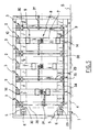
- the device for bending comprises a frame 1 on which are alternately mounted modules bending generally designated in 2 and modules transfer generally designated in 3, here three modules 2 and four transfer modules 3.
- the frame 1 comprises a base 4 supporting two parallel beams 5.
- Each spar 5 is formed of a metal profile such as aluminum having a substantially rectangular cross section and having longitudinal grooves 6 having a substantially T-shaped cross section
- Each bending module 2 includes a profile support 7 on which are mounted a holding member (here unique) with the general reference 8 and two bending members with the general reference 9 each extending on one side of the holding member 8.
- the support profile 7 is formed by a profile in metal such as aluminum having a cross section substantially rectangular and having grooves longitudinal 10 having a cross section substantially T-shaped
- the holding member 8 comprises an upright 11 having a lower end secured to a base 12 for fixing to the support profile 7 and one end opposite equipped with a clamp 13 of known type arranged to hold an element to be bent by clamping, by example a metal tube, along an axis 14 parallel to the support profile 7.
- Each bending member 9 further comprises a bracket 15 having a lower end 16 forming a mounting base to the support profile 7 and a upper end 17 in which is formed, in a plane perpendicular to the support profile 7, a housing 18 in an arc receiving a sliding slide 19 also in an arc.
- Housing 18 and the slide 19 extend in a plane perpendicular to the holding axis 14 and are centered on the latter.
- the slide 19 here extends over a angle of about 90 °.
- the housing 18 is here closed by a cover 20 held on the end 17 by screws 21 which, when screwed, tighten the slide 19 in the desired angular position between the cover 20 and the bottom of the housing 18 thus immobilizing the slide 19 in the angular position desired by compared to the amount 15.
- Each bending member 9 also includes a rotolinear cylinder 22 whose body is fixed, here by screws, on one end of the slide 19 so that extend transversely to the axis of holding 14.
- the rod of the jack 22 has one end free fitted with a bending head 23.
- the bending head bending 23 comprises in a manner known per se a roller 24 centered on the pivot axis 25 of the cylinder rod 22 and an eccentric roller 26 with an axis parallel to that of the roller 24.
- the rollers 24, 26 are provided with a groove peripheral having a cross section corresponding to that of the tube to be bent.
- the cylinder 22 is further connected to the gallows 15 by a system positional, constituted here by the slide 19 in arc of circle.
- the jack 22 is thus fixed to one end of the slide 19 so that the axis of the rod of said cylinder either forced to pivot around the holding axis 14, essentially in a plane perpendicular to said axis.
- the rod of the jack 22 slides between an extended position, in which the cross-sectional housing circular defined by the grooves of the rollers 24, 26 is usually centered on the holding axis 14, and a retracted position. If so, it is entirely possible to position this housing, in the position output of cylinder 22, so that it does not coincide exactly with the retaining pin 14, in order to perform a bend on a part of the tube extending outside said axis.
- the cylinder 22 and the clamp 13 are supplied with air compressed via standard lines respectively along the slide 19 and the gallows 15 and along the upright 11 to be connected to a compressed air control and supply device not shown here.
- the holding member 8 and the bending 9 are fixed on the support profile 7 of so that they can be adjustable in position by compared to others along this support profile.
- the bending members 9 are for example fixed by through bolts 27 passing through the base 16 and having a lower end received in one of grooves 10 of the support profile 7. It is understood that, when the bolts 27 are loose, the bending 9 can be moved along the profile support 7.
- the holding member 8 can be fixed on the support profile 7 in the same way or permanently.
- Each transfer module 3 includes him a support profile 28 identical to the support profile 7 and parallel to it, and a shaft 29 mounted on the support profile 28 by means of bearings 30 to rotate around its longitudinal direction which extends parallel to the retaining axis 14.
- Each transfer module 3 also includes an arm manipulator 31 preferably extending perpendicular to the holding axis 14 and having a end forming a clamp 32 of the shaft 29 allowing adjustable positioning of the arm manipulator 31 along the shaft 29, and one end opposite equipped with a known type of gripping means such as a clamp 33, connected by current pipes along the manipulator arm 31 to a device known to compressed air supply and control no shown here.
- the shafts 29 of the transfer modules 3 are connected to each other via a rod 34 (visible in FIG. 5) articulated to a crankpin 35 attached to one end of each shaft 29 of way to transform an alternative movement of translation applied (by a means not shown) to the control rod 34 in reciprocating rotary motion trees 29 and in a pendulum movement of the arms manipulators 31.
- a rod 34 visible in FIG. 5
- crankpin 35 attached to one end of each shaft 29 of way to transform an alternative movement of translation applied (by a means not shown) to the control rod 34 in reciprocating rotary motion trees 29 and in a pendulum movement of the arms manipulators 31.
- the support profiles 7 and 28 are fixed to the side members 5 in a similar manner to the members holding 9 on the support profile 7, so that ability to be positioned relative to each other along the longitudinal members 5.
- the manipulator arm 31 of each transfer module 3 is then preferably telescopic.
- the frame 1 is associated with a upstream assembly 36 for supplying bending tubes of known type (for example comprising an elevator) and a downstream assembly 35 for bending the bent tubes also of known type.
- a upstream assembly 36 for supplying bending tubes of known type (for example comprising an elevator) and a downstream assembly 35 for bending the bent tubes also of known type.
- the side members 5 extend horizontally.
- Bending modules 2 realize six bends on each tube from the ends of these to their middle part, each bending module 2 performing two bends.
- the holding member 8 being disposed between the two bending members 9, the the tube is maintained on its middle part which thus remains straight and allows to keep a fixed positioning reference of a module bending to another so simplifying the positioning of the jacks 22 whose head 23 intervenes on a straight portion centered on the holding axis 14.
- the manipulator arm 31 of the transfer module 3 adjacent to the power supply 36 is movable between a first position in which he grabs a tube to bend in the power supply 36 and a second position in which he positions this tube in the holding member 8 of the bending module 2 adjacent.
- the manipulator arm 31 of the transfer module 3 adjacent to the evacuation assembly is mobile between a position in which it grasps the bent tube in the bending module 2 performing the last two bends and a second position in which it deposits the curved element in the assembly Evacuation 37.
- Each of the other transfer modules 3 located between these two transfer modules to his arm manipulator 31 which is movable between a position in which he grabs a tube to bend in a module bending 2 upstream and a position in which it positions the tube in a downstream bending module 2 to transport the tube to be bent from a module upstream bending to a downstream bending module.
- clamps 13 and 33 must hold firmly the tube to prevent it from swing. It is indeed important that the orientation angular of the tube around its longitudinal direction parallel to the holding axis 14 is always known from one bending module 2 to the other because it is she who has conditioning the positioning of the bending cylinders.
- the transfer module consists of a substantially straight guide horizontal placed above the bending module (s) transversely to the holding axis, with a carriage sliding mounted on this guide and provided with a means of grip can be moved vertically, in accordance with an overhead crane type installation or portal well known to those skilled in the art.
- the tubes are transferred from a feeding station upstream of the chain to the first bending module, then from close by close to the following, and finally to a bent tubes reception station.
- the module transfer is able to select the module (s) of bending on which the operations of bending, for example by skipping one or more positions bending.
- the positioning of the jacks 22 in each bending module is obtained on the one hand by adjusting the position of the bending members 9 relative to the holding member 8 and on the other hand by adjusting the angular position of each cylinder 22 around the axis of hold 14. This last adjustment is made in moving the slide 19 relative to the stem 15 and possibly by mounting the cylinder 22 on the other end of the slide 19.
- the bending head 23 is angularly adjustable around the axis of the jack 22, so as to determine the bending angle to be achieved, in accordance with conventional bending technique using this type of cylinder.
- reconfigurations of the bending members with respect to holding members can be automatically performed on a case-by-case basis according to each type of bending tube occurring upstream of the chain.
- pairs of bending cylinders linear, arranged face to face or side by side may be substituted for rotolinear bending cylinders.
- the rotary bending by winding is replaced by linear bending by stamping.
- each bending module can include two holding members each associated with a holding member bending.
- This provision is particularly useful when the element to be bent comprises two tubes metallic connected to each other by a pipe flexible intermediate, in an end-to-end arrangement, each holding member ensuring positioning of one of the metal tubes.
- the length of the flexible pipe may vary by element to bend to another, we can plan to mount one of the holding members and the associated bending member on a carriage adjustable in position along the profile support. It is also possible to order automatically the movements of the carriage by via a length measurement sensor flexible driving or by any other means.
- the module in this case may be arranged so as to have two manipulator arms to grab the item to be bent by metal tubes.
Abstract
Description
La présente invention concerne un dispositif de cintrage d'éléments métalliques allongés et notamment des tubes en acier, cuivre, ou aluminium destinés par exemple à constituer des canalisations destinées à l'automobile pour le transport de liquide de frein, de carburant, de fluide de réfrigération, ou de liquide de direction assistée.The present invention relates to a device for bending of elongated metal elements and in particular steel, copper, or aluminum tubes for example of building pipes for automotive for transporting brake fluid, fuel, coolant, or coolant power steering.
Le cintrage d'un tube consiste à déformer plastiquement et localement le tube de manière à former un coude. La plupart des dispositifs de cintrage connus mettent en oeuvre soit un procédé de cintrage par emboutissage, soit un procédé de cintrage rotatif.Bending a tube consists of deforming plastically and locally the tube so as to form an elbow. Most known bending devices implement either a bending process by stamping, a rotary bending process.
Dans le cintrage par emboutissage, un galet mobile solidaire de la tige d'un vérin linéaire est appliqué selon une direction transversale contre une extrémité libre d'un tube maintenu dans un étau pour enrouler partiellement celle-ci autour d'un galet fixe.In stamping bending, a roller movable integral with the rod of a linear cylinder is applied in a transverse direction against a free end of a tube held in a vice for partially wind it around a fixed roller.
Dans le cintrage rotatif, l'extrémité libre d'un tube maintenu dans un étau est disposée dans une tête de cintrage comprenant deux galets d'axes parallèles, entre lesquels s'étend le tube, et qui sont montés sur un support solidaire de la tige d'un vérin rotolinéaire (on rappelle que dans un vérin rotolinéaire, la tige coulisse le long de son axe longitudinal et/ou pivote autour de celui-ci) . La rotation de la tige provoque le cintrage du tube, un des galets enroulant partiellement le tube autour de l'autre galet.In rotary bending, the free end of a tube held in a vice is arranged in a head bending comprising two rollers with parallel axes, between which extend the tube, and which are mounted on a support integral with the rod of a rotolinear cylinder (on recalls that in a rotolinear cylinder, the rod slides along its longitudinal axis and / or pivots around it). The rotation of the rod causes the bending of the tube, one of the rollers partially winding the tube around the other roller.
En général, les industriels mettant en oeuvre de tels procédés de cintrage utilisent deux types de machines.In general, industrialists implementing such bending processes use two types of machines.
Dans le premier type, la machine comporte un bâti sur lequel est fixé au moins un étau de maintien du tube à cintrer et, pour chaque coude à réaliser, un vérin de cintrage dans une position précise correspondant à la position du coude à réaliser sur le tube. De telles machines, dédiées à la réalisation d'un tube particulier, sont relativement peu onéreuses et sont donc rentables pour des productions de grande série. Une telle machine est cependant relativement longue à fabriquer. En outre, lorsque la géométrie du tube à réaliser doit être modifiée pour que le tube satisfasse à de nouvelles contraintes (par exemple, dans le cas d'une conduite de transport de liquide de frein dans un véhicule, ces contraintes peuvent être liées au passage d'un système de freinage classique à un système à anti-blocage de roues, d'un poste de conduite à gauche à un poste de conduite à droite, d'un système de frein à tambour à un système de frein à disque, à la modification d'un coude engendrant un bruit ou une usure importante...) nécessitent de renvoyer la machine à l'atelier pour que soient effectuées les modifications correspondantes du positionnement des vérins de cintrage. Cette opération requiert le démontage de la machine et s'avère relativement longue et coûteuse.In the first type, the machine has a frame on which is fixed at least one vice holding the tube to bend and, for each elbow to be produced, a bending cylinder in a precise position corresponding to the position of the elbow to be produced on the tube. Such machines, dedicated to the realization of a tube, are relatively inexpensive and are therefore profitable for large productions series. Such a machine is however relatively long to manufacture. Furthermore, when the geometry of the tube to be produced must be modified so that the tube meet new constraints (for example, in the case of a brake fluid transport line in a vehicle, these constraints can be linked to transition from a conventional braking system to a system with anti-lock braking system, from a driving position on the left to a driving station on the right, from a brake system to drum to a disc brake system to the modification of an elbow causing noise or wear important ...) require to return the machine to the workshop to make the changes corresponding to the positioning of the cylinders bending. This operation requires dismantling the machine and is relatively long and expensive.
Dans le deuxième type, la machine comporte une ou plusieurs têtes de cintrage dont les axes sont numérisés et des moyens pour déplacer cette tête de cintrage par rapport au tube. Cette machine est très flexible et donc bien adaptée à la réalisation de pièces de petite et moyenne série. Toutefois, la nécessité de positionner la tête de cintrage pour chaque coude rend une telle machine lente et peu précise. Par ailleurs, ces machines sont coûteuses et ce d'autant plus que la précision des pièces à réaliser est élevée.In the second type, the machine has a or more bending heads whose axes are scanned and means to move this head from bending with respect to the tube. This machine is very flexible and therefore well suited to the production of parts small and medium series. However, the need to positioning the bending head for each bend makes such a slow and imprecise machine. Otherwise, these machines are expensive and especially since the precision of the parts to be produced is high.
On connaít par les documents US-A-4 604 885, US-A-5 765 426 et DE-A-4 242 002 des dispositifs de cintrage composés d'un organe de maintien central entouré de deux organes de cintrage montés de façon réglable sur un bâti. We know from documents US-A-4 604 885, US-A-5 765 426 and DE-A-4 242 002 of the bending composed of a central holding member surrounded by two bending members mounted so adjustable on a frame.
En particulier, le document US-A-4 604 885
décrit un dispositif de cintrage d'éléments métalliques
allongés, notamment des éléments tubulaires, comprenant
au moins un module de cintrage monté sur un bâti, ledit
module comportant un profilé support sur lequel est fixé
au moins un organe de maintien d'un élément à cintrer
dans une position centrée sur un axe parallèle au
profilé support, et au moins un organe de cintrage,
conformément au préambule de la revendication 1.In particular, document US-A-4 604 885
describes a device for bending metallic elements
elongated, in particular tubular elements, comprising
at least one bending module mounted on a frame, said
module comprising a support profile on which is fixed
at least one member for holding an element to be bent
in a position centered on an axis parallel to the
support profile, and at least one bending member,
according to the preamble of
Les organes de cintrage sont généralement montés sur une potence portant une tête de cintrage travaillant dans l'axe de maintien de la pièce à cintrer, la tête étant selon le cas orientable autour de l'axe de maintien par un moyen positionnel manoeuvrant ladite tête dans un plan perpendiculaire à l'axe.The bending members are generally mounted on a stem carrying a working bending head in the retaining axis of the workpiece, the head depending on the case, orientable around the axis of holding by a positional means operating said head in a plane perpendicular to the axis.
Ces dispositifs astreignent la tête de cintrage à rester dans l'axe de maintien, laquelle ne peut s'en écarter de par son montage. Ceci est un inconvénient lorsque par exemple il faut dégager la tête pour permettre le positionnement d'un élément à cintrer, ou lorsqu'il faut effectuer un cintrage en dehors de l'axe de maintien.These devices compel the bending head to remain in the holding axis, which cannot be set aside by its mounting. This is a disadvantage when for example you have to clear your head to allow the positioning of an element to be bent, or when it is necessary to bend off the axis holding.
A cet égard, on peut citer le document US-A-4 945 747 qui décrit un dispositif analogue à ceux décrits précédemment, dans lequel la tête de cintrage est fixée à l'extrémité d'un bras robotisé, autorisant un désaxage de la tête de cintrage. Il s'agit d'une solution techniquement intéressante, mais très onéreuse à mettre en oeuvre.In this regard, document US-A-4 may be cited 945,747 which describes a device similar to those described previously, in which the bending head is fixed at the end of a robotic arm, allowing an offset of the bending head. It is a solution technically interesting, but very expensive to put in action.
L'arrière-plan technologique relatif aux têtes de cintrage est enfin illustré par le document DE-A-38 11 891.The technological background relating to heads of bending is finally illustrated by document DE-A-38 11,891.
Le but de l'invention est de proposer un dispositif de cintrage qui soit économique, susceptible d'être reconfiguré de manière simple pour faire face à des modifications de géométrie ou de dimensions des produits à réaliser et posséder une flexibilité importante.The object of the invention is to propose a economical, susceptible bending device to be reconfigured in a simple way to deal with modifications to the geometry or dimensions of products to be made and have flexibility important.
En vue de la réalisation de ce but, on prévoit, selon l'invention, un dispositif de cintrage du type précité, dans lequel l'organe de cintrage comporte une potence fixée de façon réglable en position le long du profilé support et au moins un vérin de cintrage dont la tige est équipée d'une tête de cintrage, ledit vérin étant relié à la potence par un système positionnel comportant un coulisseau en arc de cercle, monté de manière réglable en position sur la potence et lié au vérin de cintrage à l'une de ses extrémités de façon que l'axe de la tige du vérin soit astreint à pivoter autour de l'axe de maintien dans un plan perpendiculaire audit axe.With a view to achieving this goal, provision is made, according to the invention, a bending device of the type mentioned above, in which the bending member comprises a stem fixedly adjustable in position along the support profile and at least one bending cylinder, the rod is equipped with a bending head, said cylinder being connected to the stem by a positional system comprising a slide in an arc of a circle, mounted adjustable in position on the stem and linked to bending cylinder at one of its ends so that the axis of the cylinder rod is forced to pivot around of the retaining axis in a plane perpendicular to said audit axis.
Ainsi, le réglage de la position de l'organe de cintrage par rapport à l'organe de maintien permet de modifier la position du coude à réaliser sur l'élément allongé, et le pivotement du vérin de cintrage autour de l'axe de maintien permet de modifier l'orientation du coude par rapport à la partie de l'élément allongé qui est reçue dans l'organe de maintien. Ces différents réglages permettent donc d'obtenir de manière simple différentes configurations de cintrage.Thus, the adjustment of the position of the organ of bending with respect to the holding member makes it possible to modify the position of the elbow to be produced on the element elongated, and the pivoting of the bending cylinder around the retaining pin allows the orientation of the bend in relation to the part of the elongated element which is received in the holding member. These different settings therefore make it possible to obtain in a simple manner different bending configurations.
Selon une caractéristique particulière, le module de cintrage comprend deux organes de cintrage s'étendant chacun d'un côté de l'organe de maintien.According to a particular characteristic, the bending module includes two bending members each extending on one side of the holding member.
Avantageusement, le vérin de cintrage est un vérin rotolinéaire.Advantageously, the bending cylinder is a rotolinear cylinder.
L'orientation de la tête de cintrage autour de son axe de pivotement se combine avec le pivotement du vérin de cintrage autour de l'axe de maintien pour obtenir un grand nombre de géométries de coudes conjuguant des orientations et des angles différents.The orientation of the bending head around its pivot axis combines with the pivoting of the bending cylinder around the retaining axis for get a lot of elbow geometries combining different orientations and angles.
De préférence alors, le système positionnel autorise une plage de pivotement du vérin de cintrage d'environ 180°.Preferably then, the positional system allows a pivot range of the bending cylinder about 180 °.
Un maximum de géométries de coudes peut de la sorte être obtenu.A maximum of elbow geometries can so be obtained.
Selon une caractéristique additionnelle, le dispositif comprend au moins un module de transfert d'éléments à cintrer comportant un profilé support sur lequel est monté pour pivoter un arbre parallèle à l'axe de maintien et au moins un bras manipulateur ayant une extrémité solidaire dudit arbre pour s'étendre transversalement par rapport à celui-ci et une extrémité opposée équipée d'un moyen de préhension.According to an additional characteristic, the device includes at least one transfer module of bending elements comprising a support profile on which is mounted to pivot a shaft parallel to the axis holding and at least one manipulator arm having a end integral with said shaft to extend transversely to it and one end opposite equipped with a gripping means.
Le module de transfert permet de manière simple d'alimenter en éléments à cintrer le module de cintrage ou d'évacuer de celui-ci les éléments cintrés. Cette réalisation à l'aide d'un bras manipulateur présente l'avantage d'un encombrement limité conférant au dispositif de cintrage une structure compacte.The transfer module allows in a simple way to supply elements to bend the bending module or to evacuate from it the curved elements. This realization using a manipulator arm present the advantage of a limited size giving the bending device a compact structure.
De préférence alors, le bras manipulateur est télescopique et les profilés support des modules de cintrage et de transfert sont montés sur le bâti pour être réglables en position l'un par rapport à l'autre.Preferably then, the manipulator arm is telescopic and support profiles for the bending and transfer are mounted on the frame for be adjustable in position relative to each other.
Cette disposition est particulièrement avantageuse dans les dispositifs de cintrage comprenant plusieurs modules de cintrage et plusieurs modules de transfert, car elle permet une exploitation optimale de l'espace disponible en fonction de l'encombrement des pièces à réaliser et du nombre de modules de cintrage employés.This provision is particularly advantageous in bending devices comprising several bending modules and several transfer, because it allows optimal exploitation of the space available depending on the size of the parts to be produced and the number of bending modules employees.
Alternativement, le module de transfert comporte au moins un guide rectiligne sensiblement horizontal s'étendant transversalement à l'axe de maintien, et au dessus du module de cintrage, sur lequel est monté coulissant au moins un chariot muni d'un organe de préhension monté mobile verticalement sur ce chariot. Alternatively, the transfer module includes at least one substantially horizontal straight guide extending transversely to the retaining axis, and to top of the bending module, on which is mounted sliding at least one carriage provided with a grip mounted vertically movable on this carriage.
Ce second type de module de transfert permet de la même façon d'alimenter en éléments à cintrer le module de cintrage ou d'évacuer de celui-ci les éléments cintrés.This second type of transfer module allows the same way of supplying elements to bend the bending module or to evacuate from it the elements curved.
Avantageusement, au moins le profilé support du module de cintrage est monté sur le bâti pour s'étendre verticalement.Advantageously, at least the support profile of the bending module is mounted on the frame to extend vertically.
L'encombrement du dispositif de cintrage est de la sorte limité et le dispositif de cintrage ne nécessite qu'une surface au sol de dimensions réduites.The size of the bending device is the limited sort and the bending device does not requires only a small floor space.
Selon une autre caractéristique particulière, le module de cintrage comprend deux organes de maintien associés chacun à un organe de cintrage, l'un des organes de maintien et l'organe de cintrage associé étant montés sur un chariot réglable en position le long du profilé support. Ceci sera notamment intéressant dans le cas où les éléments à cintrer sont de structure hybride, en étant constitués par des éléments bout à bout alternativement souples et rigides.According to another particular characteristic, the bending module includes two holding members each associated with a bending member, one of the holding members and the associated bending member being mounted on a carriage adjustable in position along of the support profile. This will be particularly interesting in the case where the elements to be bent are of structure hybrid, being made up of butt elements alternately flexible and rigid toe.
Enfin, on pourra prévoir que l'organe de maintien, l'organe de cintrage et l'éventuel module de transfert sont chacun motorisés et commandés de façon à ce que leur position spatiale soit mémorisable dans le cadre d'une commande automatisée du dispositif.Finally, provision may be made for the support, the bending member and the possible module transfer are each motorized and controlled so as to that their spatial position is memorable in the automated device control.
D'autres caractéristiques et avantages de l'invention ressortiront à la lecture de la description qui suit d'un mode de réalisation particulier non limitatif de l'invention.Other features and benefits of the invention will emerge on reading the description which follows from a particular embodiment not limiting of the invention.
Il sera fait référence aux dessins annexés, parmi lesquels :
- la figure 1 est une vue partielle en perspective d'un dispositif de cintrage selon l'invention, comportant un module de cintrage ici encadré de deux modules de transfert,
- la figure 2 est une vue en élévation d'un organe de cintrage selon une direction longitudinale du profilé support, avec un détail de la tête de cintrage à plus grande échelle,
- la figure 3 est une vue analogue à la figure 2 selon une direction transversale du profilé support,
- la figure 4 est une vue schématique en élévation d'un dispositif de cintrage conforme à l'invention selon une configuration particulière,
- la figure 5 est une vue schématique en élévation d'un dispositif de cintrage selon une variante de configuration.
- FIG. 1 is a partial perspective view of a bending device according to the invention, comprising a bending module here framed by two transfer modules,
- FIG. 2 is an elevation view of a bending member in a longitudinal direction of the support profile, with a detail of the bending head on a larger scale,
- FIG. 3 is a view similar to FIG. 2 in a transverse direction of the support profile,
- FIG. 4 is a diagrammatic elevation view of a bending device according to the invention in a particular configuration,
- Figure 5 is a schematic elevational view of a bending device according to a variant configuration.
En référence aux figures, le dispositif de
cintrage conforme à l'invention comprend un bâti 1 sur
lequel sont montés de manière alternée des modules de
cintrage généralement désignés en 2 et des modules de
transfert généralement désignés en 3, ici trois modules
de cintrage 2 et quatre modules de transfert 3.With reference to the figures, the device for
bending according to the invention comprises a
Le bâti 1 comprend un piétement 4 supportant
deux longerons 5 parallèles. Chaque longeron 5 est formé
d'un profilé en métal tel que l'aluminium ayant une
section transversale sensiblement rectangulaire et
comportant des rainures longitudinales 6 ayant une
section transversale sensiblement en forme de T.The
Chaque module de cintrage 2 comprend un profilé
support 7 sur lequel sont montés un organe de maintien
(ici unique) portant la référence générale 8 et deux
organes de cintrage portant la référence générale 9
s'étendant chacun d'un côté de l'organe de maintien 8.Each
Le profilé support 7 est formé d'un profilé en
métal tel que l'aluminium ayant une section transversale
sensiblement rectangulaire et comportant des rainures
longitudinales 10 ayant une section transversale
sensiblement en forme de T.The
L'organe de maintien 8 comprend un montant 11
ayant une extrémité inférieure solidaire d'une embase 12
de fixation au profilé support 7 et une extrémité
opposée équipée d'une pince 13 de type connu agencée
pour maintenir par serrage un élément à cintrer, par
exemple un tube métallique, le long d'un axe 14
parallèle au profilé support 7.The
Chaque organe de cintrage 9 comprend en outre
une potence 15 ayant une extrémité inférieure 16 formant
une embase de fixation au profilé support 7 et une
extrémité supérieure 17 dans laquelle est ménagé, dans
un plan perpendiculaire au profilé support 7, un
logement 18 en arc de cercle recevant à coulissement un
coulisseau 19 également en arc de cercle. Le logement 18
et le coulisseau 19 s'étendent dans un plan
perpendiculaire à l'axe de maintien 14 et sont centrés
sur ce dernier. Le coulisseau 19 s'étend ici sur un
angle d'environ 90°. Le logement 18 est ici obturé par
un couvercle 20 maintenu sur l'extrémité 17 par des vis
21 qui, lorsqu'elles sont vissées, serrent le coulisseau
19 dans la position angulaire désirée entre le couvercle
20 et le fond du logement 18 immobilisant ainsi le
coulisseau 19 dans la position angulaire désirée par
rapport au montant 15.Each
Chaque organe de cintrage 9 comprend également
un vérin rotolinéaire 22 dont le corps est fixé, ici par
des vis, sur une extrémité du coulisseau 19 de manière à
s'étendre transversalement par rapport à l'axe de
maintien 14. La tige du vérin 22 possède une extrémité
libre équipée d'une tête de cintrage 23. La tête de
cintrage 23 comprend de façon connue en soi un galet 24
centré sur l'axe de pivotement 25 de la tige du vérin 22
et un galet 26 excentré et d'axe parallèle à celui du
galet 24. Les galets 24, 26 sont pourvus d'une gorge
périphérique ayant une section transversale
correspondant à celle du tube à cintrer. Le vérin 22 est
en outre relié à la potence 15 par un système
positionnel, constitué ici par le coulisseau 19 en arc
de cercle. Le vérin 22 est ainsi fixé à une extrémité du
coulisseau 19 de façon que l'axe de la tige dudit vérin
soit astreint à pivoter autour de l'axe de maintien 14,
essentiellement dans un plan perpendiculaire audit axe.
La tige du vérin 22 coulisse entre une position sortie,
dans laquelle le logement de section transversale
circulaire défini par les gorges des galets 24, 26 est
de façon habituelle centré sur l'axe de maintien 14, et
une position rentrée. Le cas échéant, il est tout à fait
possible de positionner ce logement, dans la position
sortie du vérin 22, de sorte qu'il ne coïncide pas
exactement avec l'axe de maintien 14, en vue d'effectuer
un cintrage sur une partie du tube s'étendant hors dudit
axe.Each bending
Le vérin 22 et la pince 13 sont alimentés en air
comprimé par l'intermédiaire de conduites courant
respectivement le long du coulisseau 19 et de la potence
15 et le long du montant 11 pour être raccordées à un
dispositif de commande et d'alimentation en air comprimé
non représenté ici.The
L'organe de maintien 8 et les organes de
cintrage 9 sont fixés sur le profilé support 7 de
manière à pouvoir être réglables en position les uns par
rapport aux autres le long de ce profilé support. Les
organes de cintrage 9 sont par exemple fixés par
l'intermédiaire de boulons 27 traversant l'embase 16 et
ayant une extrémité inférieure reçue dans une des
rainures 10 du profilé support 7. On comprend que,
lorsque les boulons 27 sont desserrés, les organes de
cintrage 9 peuvent être déplacés le long du profilé
support 7. L'organe de maintien 8 peut être fixé sur le
profilé support 7 de la même manière ou à demeure.The holding
Chaque module de transfert 3 comprend quant à
lui un profilé support 28 identique au profilé support 7
et parallèle à celui-ci, et un arbre 29 monté sur le
profilé support 28 par l'intermédiaire de paliers 30
pour pivoter autour de sa direction longitudinale qui
s'étend parallèlement à l'axe de maintien 14. Chaque
module de transfert 3 comprend également un bras
manipulateur 31 s'étendant de préférence
perpendiculairement à l'axe de maintien 14 et ayant une
extrémité formant un collier de serrage 32 de l'arbre 29
permettant un positionnement réglable du bras
manipulateur 31 le long de l'arbre 29, et une extrémité
opposée équipée d'un moyen de préhension de type connu
tel qu'une pince 33, raccordé par des conduites courant
le long du bras manipulateur 31 à un dispositif connu de
commande et d'alimentation en air comprimé non
représenté ici.Each
Les arbres 29 des modules de transfert 3 sont
reliés les uns aux autres par l'intermédiaire d'une tige
de commande 34 (visible sur la figure 5) articulée à un
maneton 35 fixé sur une extrémité de chaque arbre 29 de
manière à transformer un mouvement alternatif de
translation appliqué (par un moyen non représenté) à la
tige de commande 34 en un mouvement rotatif alternatif
des arbres 29 et en un mouvement de balancier des bras
manipulateurs 31.The
Avantageusement, les profilés support 7 et 28
sont fixés aux longerons 5 de façon analogue aux organes
de maintien 9 sur le profilé support 7, de manière à
pouvoir être positionnés les uns par rapport aux autres
le long des longerons 5. Le bras manipulateur 31 de
chaque module de transfert 3 est alors de préférence
télescopique.Advantageously, the support profiles 7 and 28
are fixed to the
A la figure 4, le bâti 1 est associé à un
ensemble amont 36 d'alimentation en tubes à cintrer de
type connu (par exemple comportant un élévateur) et un
ensemble aval 35 d'évacuation des tubes cintrés
également de type connu.In FIG. 4, the
Dans ce dispositif, les longerons 5 s'étendent
horizontalement.In this device, the
Les modules de cintrage 2 réalisent six coudes
sur chaque tube à partir des extrémités de ceux-ci vers
leur partie médiane, chaque module de cintrage 2
effectuant deux coudes. L'organe de maintien 8 étant
disposé entre les deux organes de cintrage 9, le
maintien du tube est assuré sur sa partie médiane qui
reste ainsi rectiligne et permet de conserver un
référentiel de positionnement fixe d'un module de
cintrage à un autre simplifiant de la sorte le
positionnement des vérins 22 dont la tête 23 intervient
sur une portion rectiligne centrée sur l'axe de maintien
14.
Le bras manipulateur 31 du module de transfert 3
adjacent à l'ensemble d'alimentation 36 est mobile entre
une première position dans laquelle il saisit un tube à
cintrer dans l'ensemble d'alimentation 36 et une
deuxième position dans laquelle il positionne ce tube
dans l'organe de maintien 8 du module de cintrage 2
adjacent. Le bras manipulateur 31 du module de transfert
3 adjacent à l'ensemble d'évacuation est quant à lui
mobile entre une position dans laquelle il saisit le
tube cintré dans le module de cintrage 2 effectuant les
deux derniers cintrages et une deuxième position dans
laquelle il dépose l'élément cintré dans l'ensemble
d'évacuation 37. Chacun des autres modules de transfert
3 situés entre ces deux modules de transfert a son bras
manipulateur 31 qui est mobile entre une position dans
laquelle il saisit un tube à cintrer dans un module de
cintrage 2 amont et une position dans laquelle il
positionne le tube dans un module de cintrage 2 aval
pour assurer le transport du tube à cintrer d'un module
de cintrage amont vers un module de cintrage aval. On
notera que les pinces 13 et 33 doivent maintenir
fermement le tube pour empêcher que celui-ci puisse
pivoter. Il est en effet important que l'orientation
angulaire du tube autour de sa direction longitudinale
parallèle à l'axe de maintien 14 soit toujours connue
d'un module de cintrage 2 à l'autre car c'est elle qui a
conditionné le positionnement des vérins de cintrage.The
Par ailleurs, on comprend que la décomposition par modules de l'opération de cintrage autorise une grande flexibilité d'emploi du dispositif. Ainsi, on peut réaliser sur une même machine deux séries de tubes ayant des géométries différentes en utilisant par exemple un seul module de cintrage pour la réalisation d'un des tubes et deux modules de cintrage pour l'autre tube. Les modules de cintrage non utilisés pour un tube ne servent pas, et sont inactivés (position reculée du vérin rotolinéaire 22).Furthermore, we understand that the decomposition by modules of the bending operation allows a great flexibility of use of the device. So, we can produce two series of tubes on the same machine having different geometries using by example a single bending module for the realization one of the tubes and two bending modules for the other tube. Bending modules not used for a tube are not used, and are inactivated (remote position of rotolinear cylinder 22).
Alternativement, et selon un mode particulier de réalisation (non représenté ici), le module de transfert est composé d'un guide rectiligne sensiblement horizontal placé au-dessus du ou des modules de cintrage transversalement à l'axe de maintien, avec un chariot monté coulissant sur ce guide et muni d'un moyen de préhension pouvant se mouvoir verticalement, conformément à un montage de type pont roulant ou portique bien connu de l'homme de l'art.Alternatively, and according to a particular mode of realization (not shown here), the transfer module consists of a substantially straight guide horizontal placed above the bending module (s) transversely to the holding axis, with a carriage sliding mounted on this guide and provided with a means of grip can be moved vertically, in accordance with an overhead crane type installation or portal well known to those skilled in the art.
Grâce à ce moyen de préhension, les tubes sont transférés d'un poste d'alimentation en amont de la chaíne vers le premier module de cintrage, puis de proche en proche vers les suivants, et enfin vers un poste de réception des tubes cintrés. Eventuellement, en fonction de la nature des tubes à cintrer, le module de transfert est capable de sélectionner le ou les modules de cintrage sur lesquels s'effectuent les opérations de cintrage, par exemple en sautant un ou plusieurs postes de cintrage.Thanks to this gripping means, the tubes are transferred from a feeding station upstream of the chain to the first bending module, then from close by close to the following, and finally to a bent tubes reception station. Possibly, in depending on the nature of the tubes to be bent, the module transfer is able to select the module (s) of bending on which the operations of bending, for example by skipping one or more positions bending.
A la figure 5, on peut voir un dispositif de
cintrage dans lequel les longerons 5 s'étendent dans un
plan vertical de manière que les profilés support 14 et
28 soient verticaux. Le dispositif de cintrage repose de
préférence directement sur le sol S. On distingue
clairement le positionnement des organes de maintien 9
(représentés sous forme schématique sur cette figure)
par rapport à l'organe de maintien 8 de chaque module de
cintrage 2 permettant la réalisation des coudes à partir
des extrémités des tubes vers leur partie médiane
(l'amont et l'aval du dispositif se situent
respectivement sur la partie droite et sur la partie
gauche de la figure).In Figure 5, we can see a device
bending in which the
Le positionnement des vérins 22 dans chaque
module de cintrage est obtenu d'une part en réglant la
position des organes de cintrage 9 par rapport à
l'organe de maintien 8 et d'autre part en réglant la
position angulaire de chaque vérin 22 autour de l'axe de
maintien 14. Ce dernier réglage est effectué en
déplaçant le coulisseau 19 par rapport à la potence 15
et éventuellement en montant le vérin 22 sur l'autre
extrémité du coulisseau 19. La tête de cintrage 23 est
réglable angulairement autour de l'axe du vérin 22, de
façon à déterminer l'angle de cintrage à réaliser,
conformément à la technique de cintrage classique
utilisant ce type de vérin.The positioning of the
Bien entendu, l'invention n'est pas limitée au mode de réalisation décrit et on pourra y apporter des variantes de réalisation sans sortir du cadre de l'invention tel que défini par les revendications.Of course, the invention is not limited to described embodiment and we can bring variants without departing from the scope of the invention as defined by the claims.
On pourra prévoir que l'organe de maintien, l'organe de cintrage et l'éventuel module de transfert sont chacun motorisés et commandés de façon à ce que leur position spatiale soit mémorisable dans le cadre d'une commande automatisée du dispositif. On parvient alors à faire coopérer tous les moyens ainsi pilotés de manière automatique. En particulier, les reconfigurations des organes de cintrage vis-à-vis des organes de maintien peuvent être automatiquement réalisées au cas par cas en fonction de chaque type de tube à cintrer se présentant en amont de la chaíne.Provision may be made for the holding member, the bending member and the possible transfer module are each motorized and controlled so that their spatial position is memorable in the frame automated device control. We manage then to make cooperate all the means thus piloted of automatically. In particular, reconfigurations of the bending members with respect to holding members can be automatically performed on a case-by-case basis according to each type of bending tube occurring upstream of the chain.
En outre, des paires de vérins de cintrage linéaires, disposés face à face ou côte à côte, pourront être substituées aux vérins de cintrage rotolinéaires. Dans ce cas, le cintrage rotatif par enroulement est remplacé par un cintrage linéaire par emboutissage.In addition, pairs of bending cylinders linear, arranged face to face or side by side, may be substituted for rotolinear bending cylinders. In this case, the rotary bending by winding is replaced by linear bending by stamping.
Enfin, chaque module de cintrage peut comprendre deux organes de maintien associés chacun à un organe de cintrage. Cette disposition est particulièrement utile lorsque l'élément à cintrer comprend deux tubes métalliques reliés l'un à l'autre par une conduite intermédiaire flexible, selon un agencement bout à bout, chaque organe de maintien assurant le positionnement d'un des tubes métalliques. Lorsque la longueur de la conduite flexible est susceptible de varier d'un élément à cintrer à un autre, on peut prévoir de monter l'un des organes de maintien et l'organe de cintrage associé sur un chariot réglable en position le long du profilé support. Il est en outre possible de commander automatiquement les déplacements du chariot par l'intermédiaire d'un capteur de mesure de la longueur de la conduite flexible ou par tout autre moyen. Le module de transfert pourra dans ce cas être agencé de manière à comporter deux bras manipulateurs pour saisir l'élément à cintrer par les tubes métalliques.Finally, each bending module can include two holding members each associated with a holding member bending. This provision is particularly useful when the element to be bent comprises two tubes metallic connected to each other by a pipe flexible intermediate, in an end-to-end arrangement, each holding member ensuring positioning of one of the metal tubes. When the length of the flexible pipe may vary by element to bend to another, we can plan to mount one of the holding members and the associated bending member on a carriage adjustable in position along the profile support. It is also possible to order automatically the movements of the carriage by via a length measurement sensor flexible driving or by any other means. The module in this case may be arranged so as to have two manipulator arms to grab the item to be bent by metal tubes.
Claims (10)
Applications Claiming Priority (2)
| Application Number | Priority Date | Filing Date | Title |
|---|---|---|---|
| FR9907819A FR2795006B1 (en) | 1999-06-21 | 1999-06-21 | DEVICE FOR BENDING ELONGATED METAL ELEMENTS SUCH AS TUBES |
| FR9907819 | 1999-06-21 |
Publications (1)
| Publication Number | Publication Date |
|---|---|
| EP1065015A1 true EP1065015A1 (en) | 2001-01-03 |
Family
ID=9547041
Family Applications (1)
| Application Number | Title | Priority Date | Filing Date |
|---|---|---|---|
| EP00401712A Withdrawn EP1065015A1 (en) | 1999-06-21 | 2000-06-16 | Apparatus for bending elongate metallic objects such as tubes |
Country Status (2)
| Country | Link |
|---|---|
| EP (1) | EP1065015A1 (en) |
| FR (1) | FR2795006B1 (en) |
Cited By (8)
| Publication number | Priority date | Publication date | Assignee | Title |
|---|---|---|---|---|
| EP1291094A1 (en) * | 2001-10-02 | 2003-03-12 | FABBRICA MACCHINE CURVATUBI CRIPPA AGOSTINO S.p.A. | Draw-bending machine |
| EP1849536A1 (en) * | 2006-04-07 | 2007-10-31 | WAFIOS Aktiengesellschaft | Bending machine for rod-shaped workpieces like wire or tube |
| EP1955789A1 (en) * | 2007-02-07 | 2008-08-13 | WAFIOS Aktiengesellschaft | Bending machine |
| US7891227B2 (en) | 2007-03-14 | 2011-02-22 | Wafios Aktiengesellschaft | Gripping apparatus for gripping and holding elongated workpieces, in particular for bending machines |
| CN104190765A (en) * | 2014-07-30 | 2014-12-10 | 南京阿福汽车控制系统有限公司 | Bending machine |
| CN106623684A (en) * | 2017-01-23 | 2017-05-10 | 沈春慧 | Power cable bending device |
| CN107008826A (en) * | 2017-01-23 | 2017-08-04 | 沈春慧 | A kind of easy power cable bar folder |
| CN107008827A (en) * | 2017-01-23 | 2017-08-04 | 沈春慧 | A kind of labour-saving power cable bending device |
Citations (5)
| Publication number | Priority date | Publication date | Assignee | Title |
|---|---|---|---|---|
| US4604885A (en) * | 1983-03-31 | 1986-08-12 | Lang Thomas P | Machine for the bending of stranded material |
| DE3811891A1 (en) * | 1988-04-09 | 1989-06-15 | Semmlinger Werner | Apparatus for bending stock in strand form |
| US4945747A (en) * | 1989-05-11 | 1990-08-07 | Chuo Electric Manufacturing Co., Ltd. | Apparatus for bending elongated materials in any direction |
| DE4242002A1 (en) * | 1992-12-12 | 1994-06-16 | Herbert Hirschmiller | System for bending continuously produced material - has central material clamping unit consisting of two independently operable pairs of clamping tools |
| US5765426A (en) * | 1995-07-14 | 1998-06-16 | Usui Kokusai Sangyo Kaisha Limited | Pipe bending apparatus |
-
1999
- 1999-06-21 FR FR9907819A patent/FR2795006B1/en not_active Expired - Fee Related
-
2000
- 2000-06-16 EP EP00401712A patent/EP1065015A1/en not_active Withdrawn
Patent Citations (5)
| Publication number | Priority date | Publication date | Assignee | Title |
|---|---|---|---|---|
| US4604885A (en) * | 1983-03-31 | 1986-08-12 | Lang Thomas P | Machine for the bending of stranded material |
| DE3811891A1 (en) * | 1988-04-09 | 1989-06-15 | Semmlinger Werner | Apparatus for bending stock in strand form |
| US4945747A (en) * | 1989-05-11 | 1990-08-07 | Chuo Electric Manufacturing Co., Ltd. | Apparatus for bending elongated materials in any direction |
| DE4242002A1 (en) * | 1992-12-12 | 1994-06-16 | Herbert Hirschmiller | System for bending continuously produced material - has central material clamping unit consisting of two independently operable pairs of clamping tools |
| US5765426A (en) * | 1995-07-14 | 1998-06-16 | Usui Kokusai Sangyo Kaisha Limited | Pipe bending apparatus |
Cited By (12)
| Publication number | Priority date | Publication date | Assignee | Title |
|---|---|---|---|---|
| EP1291094A1 (en) * | 2001-10-02 | 2003-03-12 | FABBRICA MACCHINE CURVATUBI CRIPPA AGOSTINO S.p.A. | Draw-bending machine |
| US6694794B2 (en) | 2001-10-02 | 2004-02-24 | Fabbrica Macchine Curvatubi Crippa Agostino S.P.A. | Draw-bending machine |
| EP1849536A1 (en) * | 2006-04-07 | 2007-10-31 | WAFIOS Aktiengesellschaft | Bending machine for rod-shaped workpieces like wire or tube |
| US7721582B2 (en) | 2006-04-07 | 2010-05-25 | Wafios Aktiengesellschaft | Bending machine for rod-shaped workpieces made from wire, tubular material or the like |
| EP1955789A1 (en) * | 2007-02-07 | 2008-08-13 | WAFIOS Aktiengesellschaft | Bending machine |
| US7891225B2 (en) | 2007-02-07 | 2011-02-22 | Wafios Aktiengesellschaft | Bending machine |
| US7891227B2 (en) | 2007-03-14 | 2011-02-22 | Wafios Aktiengesellschaft | Gripping apparatus for gripping and holding elongated workpieces, in particular for bending machines |
| CN104190765A (en) * | 2014-07-30 | 2014-12-10 | 南京阿福汽车控制系统有限公司 | Bending machine |
| CN106623684A (en) * | 2017-01-23 | 2017-05-10 | 沈春慧 | Power cable bending device |
| CN107008826A (en) * | 2017-01-23 | 2017-08-04 | 沈春慧 | A kind of easy power cable bar folder |
| CN107008827A (en) * | 2017-01-23 | 2017-08-04 | 沈春慧 | A kind of labour-saving power cable bending device |
| CN106623684B (en) * | 2017-01-23 | 2018-11-06 | 深圳供电局有限公司 | One kind being used for power cable bending device |
Also Published As
| Publication number | Publication date |
|---|---|
| FR2795006B1 (en) | 2001-09-14 |
| FR2795006A1 (en) | 2000-12-22 |
Similar Documents
| Publication | Publication Date | Title |
|---|---|---|
| EP0194217B1 (en) | Industrial robots of the spherical type | |
| FR2521055A1 (en) | INDUSTRIAL ROBOT | |
| FR2608947A1 (en) | ROBOTISE HANDLING DEVICE AND METAL SHEET BENDING PLANT INCORPORATING SAME | |
| EP1065015A1 (en) | Apparatus for bending elongate metallic objects such as tubes | |
| CA1291697C (en) | Bending machine for tubes, bars and shopes | |
| EP1370388B1 (en) | Driving device and clamping tool equipped with same | |
| FR2906179A1 (en) | Object transfer device for displacing object i.e. bottle, has frame supporting driving unit that displaces arm such that opening of object is displaced along initial trajectory portion, along direction perpendicular to support area | |
| JP6929739B2 (en) | In particular, a support device for supporting a tube in a tube processing machine such as a laser tube cutting machine, and a tube processing machine provided with such a support device. | |
| FR2732634A1 (en) | Tool magazine attachment for machine tool | |
| WO2008142252A2 (en) | Tube cambering unit | |
| EP1775126A2 (en) | Article transfer device for a printing machine, printing machine and transfer process | |
| EP1820647A2 (en) | Machine and method for marking hollow components | |
| EP3919234B1 (en) | Device for moving objects | |
| FR2685239A1 (en) | Machine for machining workpieces from very long sections | |
| EP0402216B1 (en) | Device for the curvilinear motion of an object in contact with a surface, in particular with a convex surface | |
| FR2905622A1 (en) | Mechanical manipulator for part assembling and/or controlling machine, has cylinders one of which has shaft connected with plate, and free end, where cylinders have input shafts simultaneously driven in rotation by single driving belt | |
| EP0281488B1 (en) | Turning bending head for a tube-bending machine | |
| EP0015215B1 (en) | Workpiece loader or extractor | |
| FR2714319A1 (en) | Gripping and transport device. | |
| FR2525147A1 (en) | APPARATUS FOR LOADING AND DISCHARGING INDUSTRIAL PRESSES | |
| EP0490798A2 (en) | Crane, especially for handling | |
| FR2673586A1 (en) | MACHINE FOR THE MAINTENANCE OF A CONTACT LINE. | |
| WO2019145611A1 (en) | Machine for cutting rails of a railway track | |
| EP0307293A1 (en) | Coupling system for two bodies for instance a transportcar and a working station | |
| FR2513922A1 (en) | TOOL HOLDER TROLLEY |
Legal Events
| Date | Code | Title | Description |
|---|---|---|---|
| PUAI | Public reference made under article 153(3) epc to a published international application that has entered the european phase |
Free format text: ORIGINAL CODE: 0009012 |
|
| AK | Designated contracting states |
Kind code of ref document: A1 Designated state(s): AT BE CH CY DE DK ES FI FR GB GR IE IT LI LU MC NL PT SE |
|
| AX | Request for extension of the european patent |
Free format text: AL;LT;LV;MK;RO;SI |
|
| 17P | Request for examination filed |
Effective date: 20010504 |
|
| AKX | Designation fees paid |
Free format text: AT BE CH CY DE DK ES FI FR GB GR IE IT LI LU MC NL PT SE |
|
| GRAH | Despatch of communication of intention to grant a patent |
Free format text: ORIGINAL CODE: EPIDOS IGRA |
|
| STAA | Information on the status of an ep patent application or granted ep patent |
Free format text: STATUS: THE APPLICATION IS DEEMED TO BE WITHDRAWN |
|
| 18D | Application deemed to be withdrawn |
Effective date: 20031107 |