EP0999530A2 - Visual alerting apparatus - Google Patents
Visual alerting apparatus Download PDFInfo
- Publication number
- EP0999530A2 EP0999530A2 EP19990308448 EP99308448A EP0999530A2 EP 0999530 A2 EP0999530 A2 EP 0999530A2 EP 19990308448 EP19990308448 EP 19990308448 EP 99308448 A EP99308448 A EP 99308448A EP 0999530 A2 EP0999530 A2 EP 0999530A2
- Authority
- EP
- European Patent Office
- Prior art keywords
- motor
- telephone
- rotation
- axis
- alert
- Prior art date
- Legal status (The legal status is an assumption and is not a legal conclusion. Google has not performed a legal analysis and makes no representation as to the accuracy of the status listed.)
- Granted
Links
Images


Classifications
-
- H—ELECTRICITY
- H04—ELECTRIC COMMUNICATION TECHNIQUE
- H04M—TELEPHONIC COMMUNICATION
- H04M19/00—Current supply arrangements for telephone systems
- H04M19/02—Current supply arrangements for telephone systems providing ringing current or supervisory tones, e.g. dialling tone or busy tone
- H04M19/04—Current supply arrangements for telephone systems providing ringing current or supervisory tones, e.g. dialling tone or busy tone the ringing-current being generated at the substations
-
- H—ELECTRICITY
- H04—ELECTRIC COMMUNICATION TECHNIQUE
- H04M—TELEPHONIC COMMUNICATION
- H04M1/00—Substation equipment, e.g. for use by subscribers
- H04M1/02—Constructional features of telephone sets
- H04M1/0202—Portable telephone sets, e.g. cordless phones, mobile phones or bar type handsets
-
- H—ELECTRICITY
- H04—ELECTRIC COMMUNICATION TECHNIQUE
- H04M—TELEPHONIC COMMUNICATION
- H04M19/00—Current supply arrangements for telephone systems
- H04M19/02—Current supply arrangements for telephone systems providing ringing current or supervisory tones, e.g. dialling tone or busy tone
- H04M19/04—Current supply arrangements for telephone systems providing ringing current or supervisory tones, e.g. dialling tone or busy tone the ringing-current being generated at the substations
- H04M19/047—Vibrating means for incoming calls
Landscapes
- Engineering & Computer Science (AREA)
- Signal Processing (AREA)
- Telephone Function (AREA)
- Mobile Radio Communication Systems (AREA)
- Telephone Set Structure (AREA)
- User Interface Of Digital Computer (AREA)
- Apparatuses For Generation Of Mechanical Vibrations (AREA)
- Connection Of Motors, Electrical Generators, Mechanical Devices, And The Like (AREA)
- Lighting Device Outwards From Vehicle And Optical Signal (AREA)
Abstract
Description
- This invention relates to an alerting device for electronic equipment. It is particularly suitable for use in a portable radiotelephone to alert the user to an incoming call.
- Traditionally, a portable radiotelephone or mobile station (MS) alerts the user to an event such as an incoming call or text message (SMS), through use of an audible tone. A great variety of tones are normally provided, allowing the user to customise his alert so that it can be easily identified from amongst other telephone alerts. 'Incoming call' herein includes an incoming message.
- Such tones can, however, be intrusive and annoying to people in close proximity to the intended recipient. Currently available portable radiotelephones often come equipped with the option of a vibrating alert instead of, or as well as, the traditional audible alert. The vibrating alert causes the telephone to vibrate, and is designed to discreetly inform the user of an incoming call, if the telephone is, for instance, in the users pocket. The vibrations can be sensed by the user without the need for an intrusive, audible tone.
- The vibrating alert solution is not always appropriate, as the user must be in close physical contact with the telephone in order for the vibrations to be noticed. There are often situations in which the user will not be in physical contact with the telephone, but will wish to be alerted to an incoming call without disturbing others with an audible tone. For instance, a telephone may normally be kept in a handbag or a briefcase, where the volume of an audible tone may be disruptive, but a vibrating alert will be ineffective.
- In addition to the aforementioned alerting methods, some telephones are equipped with a small light, such as an LED, which may alternatively , or additionally, be used to signal an incoming call. However, such an alert may not be noticed, unless the telephone is at all times clearly visible. It is especially easy to miss such an alert in a brightly lit environment.
- Prior art techniques of notifying the user of an incoming call either require the telephone to produce an audible tone which may disturb others, vibrate, which requires the user to be in physical contact with the telephone, or activate an LED which is easily missed, unless the telephone is constantly within the user's field of vision.
- Similar problems are encountered with other portable electronic equipment. For instance, portable electronic organisers or PDAs (Personal Digital Assistants) are often equipped to alert the user in response to a preprogrammed diary reminder for instance. The audible alert can cause similar problems in this situation. 'Portable computer' will herein include laptop computers, PDAs, personal organisers, data capture devices and the like.
- It is notable that many portable radiotelephones now include many of the features of portable computers.
- It is desired to produce a portable electronic apparatus which may alert a user to an event, in a manner which avoids the above mentioned disadvantages.
- It is particularly desired to produce a portable radiotelephone which may alert a user to an incoming call, in a manner which avoids the above mentioned disadvantages.
- According to a first aspect of the present invention, there is provided an apparatus having a first axis of rotation, comprising a surface upon which the apparatus may be supported, and a motor, said motor comprising a rotor shaft having a second axis of rotation, the motor being activated in order to alert a user of the apparatus to an event, wherein said motor is positioned within the apparatus such that the second axis of rotation is substantially parallel to the first axis of rotation, and activation of the motor produces a turning moment causing the apparatus to rotate about the first axis.
- The apparatus may be a portable radiotelephone. The telephone is made to spin about an axis when the internal motor is activated. The principle of conservation of angular momentum ensures that all moving parts can be kept internal to the telephone housing.
- The event may be an incoming telephone call or message. A user of the telephone is thus made aware of the call without any intrusive and distracting audible alerts. Neither does he need to be in physical contact with the telephone.
- The apparatus may be a portable computer. Portable computers are often used to remind a user of an upcoming appointment, and can potentially distract others with such audible reminders. Portable computers adapted according to the invention can alert the user discreetly.
- The apparatus may be made to rotate about an axis orthogonal to, or parallel to, the structure, e.g. a table, upon which it is resting. The axis is defined by the positioning within the apparatus of the rotor shaft of the motor. Angular momentum is a vector quantity, and so the rotation induced in the apparatus is in the same direction as the rotation of the rotor shaft.
- The apparatus may rest upon any one of its suitable surfaces. It is preferable that the surface used is curved. This combines a small contact area with the supporting structure, with a pleasing look and feel.
- Alternatively, or in addition, a surface may be provided with a projection upon which it may be made to rotate.
- Rather than replacing an audible alert, the alert may be activated synchronous to such an audible alert. Thus, the apparatus will appear to rotate in time to the audible alert. With the various ring tones which are commonly provided with portable radiotelephones, the telephone may appear to 'dance' in time to the ring tone.
- The motor may be a vibrator motor. Such a motor offers the additional benefit that the apparatus may additionally make use of a vibrating alert.
- The motor may be operable in two opposing, i.e. forward and backward, directions. Apparatus so equipped may be made to oscillate about the axis of rotation.
- It is an advantage of the present invention that a user of an apparatus according to the invention may be alerted to an event concerning the apparatus in a manner which is both easily noticeable, yet relatively nondisruptive to others.
- It is a particular advantage of the present invention, that a user of a portable radiotelephone may be alerted to an incoming call in a manner which is both easily noticeable, yet relatively non-disruptive to others.
- For a better understanding of the present invention, and to understand how the same may be brought into effect, the invention will now be described, by way of example only, with reference to the appended drawings in which :
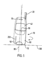
- Fig.1 shows a portable radiotelephone in accordance with the invention;
- Fig. 2 is a top view of the portable radiotelephone of Fig.1, showing the rotation of the motor, and of the entire telephone;
- Fig. 3 is a top and plan view of a motor suitable for use in a device according to one embodiment of the invention;
- Fig. 4 is a top and plan view of a vibrator motor suitable for use in a device according to another embodiment of the invention;
- Fig. 5 shows a portable radiotelephone according to a further embodiment of the invention;
- Fig. 6 shows a portable computer according to a further embodiment of the invention.
-
- Referring to Fig. 1, a
portable radiotelephone 10 is shown standing on itslower surface 70. In this particular embodiment, thetelephone 10 leans slightly to one side due to the weight distribution of the various components within the casing. Other embodiments may be envisaged in which the telephone will rest substantially orthogonal to the surface, or supporting structure, 100 upon which the telephone rests. - Illustrated are some of the standard features associated with portable radiotelephones, such as an
antenna 20, anearpiece 30, adisplay 40 and amicrophone 50 The keypad in this particular embodiment is concealed behind a slidingcover 60. - The
lower surface 70 is slightly curved, allowing the telephone to be conveniently supported on this surface whilst providing a small area of contact with the contacting surface, or supporting structure, 100 such as a desk or table, on which the telephone is placed. The area of contact is kept small, as this is the point about which the telephone will rotate in response to activation of the motor. - In this embodiment, the centre of gravity of the phone is kept as low as possible, to prevent the phone from toppling. This can be achieved by the careful placement within the telephone housing of the various components that make up the telephone. Certain components are heavier than others, e.g. the battery, and are positioned near the
lower surface 70 of the telephone. - Also illustrated is the position within the casing of the
motor 200. The motor is mounted so that the axis of rotation of the rotor shaft is substantially parallel to the axis ofrotation 90 of the telephone. - Fig. 2 shows a top view of the
telephone 10 of fig. 1. The position of themotor 200 is shown. Its direction of rotation is shown byarrow 202. The corresponding rotation of the telephone about its axis ofrotation 90, brought about by the rotation of the motor, is shown byarrow 204. - Fig. 3 shows a top and plan view of the
motor 200. The motor assembly comprises a standard DC motor, which is made to rotate in response to an incoming call. The motor is activated by the appliance of a DC voltage toelectrical terminals 210. Therotor shaft 220 of the motor is shown loaded with aweight 230 to give the arrangement a greater moment of inertia. The addition of a weight may not be necessary depending on the mass, and moment of inertia, of the entire telephone. - The motor of this embodiment measures 20mm x 7mm x 5mm, and hence can be easily incorporated into the housing without using too much of the limited space available. Other features of note of the motor are :-
- Rated Voltage:
- 1.3V
- Rated Speed:
- 10,000 rpm (+3,000, -2,000 rpm)
- Rated Current:
- 80mA
- With the
telephone 10 standing upright, resting on itslower surface 70, any rotation of themotor 200 will in turn impart a turning moment, or torque, on thetelephone 10, due to the principle of conservation of angular momentum. If the moment or torque is of sufficient magnitude, then thetelephone 10 will rotate about an axis ofrotation 90 defined by the geometry of thetelephone 10 and the area of contact with the contactingsurface 100. - In figure 1, the
geometric centre line 80 of thetelephone 10 is shown with a dashed line, but note that this is different to the line defining the axis ofrotation 90. This is due to the uneven mass distribution within the housing of this particular embodiment. If the mass distribution were altered, then thegeometric centre 80 may be made to coincide with the axis ofrotation 90 of thetelephone 10. - There is no reason why the surface upon which the telephone rests needs to be the lower surface. Fig. 5 illustrates an alternative embodiment which shows the
telephone 500 resting on itsrear surface 510. This embodiment is substantially curved in profile, and resembles the Nokia ® 8110 telephone. When placed down on itsrear surface 510, as shown, it provides a small contact area with the contactingsurface 100. In this embodiment, consideration of the centre of gravity of the telephone is not crucial, as the telephone is less likely to topple. - In this embodiment, the
motor 200 is positioned, as shown, so that the axis of rotation of therotor shaft 220 is substantially orthogonal to thesurface 100 upon which thetelephone 500 rests, and substantially parallel to the axis ofrotation 90 of the telephone. Appliance of a DC voltage to themotor 200, will, as in the previous embodiment, cause thetelephone 500 to rotate about anaxis 90, due to the conservation of angular momentum. Thearrows - In a further embodiment, it is possible to cause the
telephone 600 to rotate about anaxis 90 which is substantially parallel to the contactingsurface 100 upon which the telephone rests. Fig. 6 shows such an embodiment. Here the axis ofrotation 90 is substantially parallel to contactingsurface 100, and extends substantially orthogonal to the front of thetelephone 600. - In the view shown, the
motor 200 is viewed along itsrotor shaft 220. If it is activated so that its rotor shaft rotates alternately in two opposite directions, the telephone will appear to oscillate from side to side as indicated byarrows lower surface 630. - In a further embodiment, it is possible to achieve the effect of a visual indication of an incoming call, i.e. rotation of the telephone, combined with the benefit of a vibrating alert for occasions when the telephone is carried about the person of the user, e.g. in a pocket.
- The
regular motor 200 of the previously described embodiment is replaced with thevibrator motor 300 of Fig. 4. Thevibrator motor 300 comprises a regular motor, loaded with aneccentric mass 330. This can be seen clearly from the top view of thevibrator motor 300. Theweight 330 is concentrated around one portion of therotor shaft 220. Therotor shaft 220 defines the axis of rotation of the motor. When the motor is activated through the appliance of a DC voltage, therotor shaft 220 begins to spin, and the telephone rotates about its axis of rotation, as previously described. - If, however, a telephone equipped with a
vibrator motor 300 according to an embodiment of the invention is not free to rotate, because it is being carried in a pocket, for instance, then the vibrator motor may still be used to notify the user of an incoming call with a vibrating alert. - All the embodiments herein described may be adapted to use a motor whose rotor shaft is capable of rotating in either direction. Using such a motor, the telephone may be made to rotate in one of two opposite directions. Activation of the motor in a first direction, and then in an opposite direction, synchronous to an audible alert, may be used to make the telephone appear to 'dance' in time to the audible alert.
- More than one motor may be fitted to a telephone so that it may rotate in any one of a number of planes. For instance, one motor may be used to cause rotation while the telephone is lying on a rear surface, and another may be used to cause rotation if the telephone is standing upright.
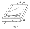
- Fig. 7 shows a
portable computer 700 according to a further embodiment of the invention. Theportable computer 700 comprises a touch-sensitive screen 710, where data is entered and displayed. Also shown areseveral function keys 720, which have special functions. Portable computers such as these are commonly used to store such information as To-Do Lists, personal address books, application programs and schedules or diaries. It is usual to provide an audible tone to alert the user to, for instance, an impending appointment. Incorporation of amotor 200 allows the portable computer to operate in the same manner as the previously described telephones i.e. it may be made to spin about an axis, in response to activation of the motor, in order to discreetly notify the user of an upcoming event. In the embodiment shown, the computer may be supported on its rear surface (not shown), or thelower surface 730. - It will be clear to the skilled man that the present invention is applicable to laptop or palmtop computers, where an alert may be used, for instance, as a reminder of an appointment, notifying arrival of a new email, or as a warning that, for instance, memory may be getting low.
- The embodiments herein described may be adapted in many ways while still performing the invention. For instance, the apparatus may be made to rotate about any suitable axis defined in terms of any surface of the apparatus.
- The outer surface upon which the apparatus rests need not be curved, but may be provided with a projection upon which the apparatus may be made to rotate.
- The present invention includes any novel feature or combination of features disclosed herein either explicitly or any generalisation thereof irrespective of whether or not it relates to the claimed invention or mitigates any or all of the problems addressed.
Claims (13)
- An apparatus having a first axis of rotation, comprising a surface upon which the apparatus may be supported, and a motor, said motor comprising a rotor shaft having a second axis of rotation, the motor being activated in order to alert a user of the apparatus to an event, wherein said motor is positioned within the apparatus such that the second axis of rotation is substantially parallel to the first axis of rotation, and activation of the motor produces a turning moment causing the apparatus to rotate about the first axis.
- An apparatus as claimed in claim 1 wherein the apparatus is a portable radiotelephone.
- An apparatus as claimed in claim 2 wherein the event is an incoming call or message.
- An apparatus as claimed in claim 1 wherein the apparatus is a portable computer.
- An apparatus as claimed in any one of the preceding claims wherein the first axis of rotation is substantially orthogonal to a structure supporting the apparatus.
- An apparatus as claimed in any one of claims 1 to 4 wherein the first axis of rotation is substantially parallel to a structure supporting the apparatus.
- An apparatus as claimed in any one of the preceding claims wherein the surface is curved.
- An apparatus as claimed in any one of the preceding claims wherein the surface is provided with a projection, about which rotation may occur.
- An apparatus as claimed in any one of the preceding claims wherein the surface is a lower surface of the apparatus.
- An apparatus as claimed in any one of claims 1 to 8 wherein the outer surface is a rear surface of the apparatus.
- An apparatus as claimed in any one of the preceding claims wherein the motor is activated synchronous to an audible alert.
- An apparatus as claimed in any one of the preceding claims wherein the motor is a vibrator motor.
- An apparatus as claimed in any one of the preceding claims wherein the motor is capable of operation in two opposing directions.
Applications Claiming Priority (2)
| Application Number | Priority Date | Filing Date | Title |
|---|---|---|---|
| GB9824422A GB2343536B (en) | 1998-11-06 | 1998-11-06 | Alerting apparatus |
| GB9824422 | 1998-11-06 |
Publications (3)
| Publication Number | Publication Date |
|---|---|
| EP0999530A2 true EP0999530A2 (en) | 2000-05-10 |
| EP0999530A3 EP0999530A3 (en) | 2000-07-19 |
| EP0999530B1 EP0999530B1 (en) | 2003-06-25 |
Family
ID=10842025
Family Applications (1)
| Application Number | Title | Priority Date | Filing Date |
|---|---|---|---|
| EP99308448A Expired - Lifetime EP0999530B1 (en) | 1998-11-06 | 1999-10-26 | Visual alerting apparatus |
Country Status (5)
| Country | Link |
|---|---|
| US (1) | US6304170B1 (en) |
| EP (1) | EP0999530B1 (en) |
| JP (1) | JP3693538B2 (en) |
| DE (1) | DE69909039T2 (en) |
| GB (1) | GB2343536B (en) |
Cited By (5)
| Publication number | Priority date | Publication date | Assignee | Title |
|---|---|---|---|---|
| NL1024042C2 (en) * | 2003-08-04 | 2005-02-07 | Global Design S A | Mobile phone, contains electric motor for making phone rotate when call or message is received |
| WO2010008665A1 (en) * | 2008-07-14 | 2010-01-21 | Sony Ericsson Mobile Communications Ab | Communication device with orientation indication of receipt of communication signal |
| US7988374B2 (en) | 2007-02-08 | 2011-08-02 | Seiko Instruments Inc. | Sheet cutting device and printer |
| FR2968489A1 (en) * | 2010-12-03 | 2012-06-08 | France Telecom | Telephone terminal for use in residential wireless telephone device, has movement generator unit producing balancing of terminal around equilibrium position when body is supported by rolling surface on plane surface of support |
| EP2869539A3 (en) * | 2013-11-04 | 2015-06-10 | Samsung Electronics Co., Ltd | An electronic device with curved bottom and operating method thereof |
Families Citing this family (14)
| Publication number | Priority date | Publication date | Assignee | Title |
|---|---|---|---|---|
| KR20000033772A (en) * | 1998-11-25 | 2000-06-15 | 윤종용 | Apparatus for announcing incoming status of portable phone and method thereof |
| GB2378617B (en) * | 2001-08-11 | 2005-09-07 | Ubinetics Ltd | A mobile device |
| US7292879B2 (en) * | 2002-12-27 | 2007-11-06 | Matorola, Inc. | Method and apparatus of alerting a user of a mobile electronic device |
| WO2004093475A1 (en) * | 2003-04-17 | 2004-10-28 | Nokia Corporation | Reminder handling |
| US9392428B2 (en) | 2003-04-17 | 2016-07-12 | Nokia Technologies Oy | Reminder handling |
| US20050215295A1 (en) * | 2004-03-29 | 2005-09-29 | Arneson Theodore R | Ambulatory handheld electronic device |
| DE102004032699A1 (en) | 2004-07-06 | 2006-02-16 | Siemens Ag | A method for remotely retrieving information stored in a telecommunications device and telecommunication device with remote retrieval functionality of stored information |
| GB0512503D0 (en) | 2005-06-18 | 2005-07-27 | Jkid Ltd | A portable device |
| US20070185647A1 (en) * | 2006-02-09 | 2007-08-09 | Nguegang Gino F | Automated in-vehicle paging system |
| CN101729616A (en) * | 2008-10-10 | 2010-06-09 | 深圳富泰宏精密工业有限公司 | Portable electronic device |
| US8558677B2 (en) | 2009-03-26 | 2013-10-15 | Gary Stephen Shuster | Tactile alerting mechanism for portable communications device |
| US8731503B2 (en) | 2010-04-29 | 2014-05-20 | Nokia Corporation | RF performance improvement |
| US8767394B1 (en) | 2011-03-21 | 2014-07-01 | Google Inc. | One-handed browsing appliance |
| US9645643B2 (en) * | 2014-06-17 | 2017-05-09 | Immersion Corporation | Mobile device with motion controlling haptics |
Citations (3)
| Publication number | Priority date | Publication date | Assignee | Title |
|---|---|---|---|---|
| US4707855A (en) * | 1985-05-31 | 1987-11-17 | Nobell Inc. | Personalized telephone signaling circuitry and device, and methods of constructing and utilizing same |
| US5801466A (en) * | 1994-12-27 | 1998-09-01 | Uniden Corporation | Vibrator attaching structure |
| FR2765431A1 (en) * | 1997-06-30 | 1998-12-31 | Motorola Inc | COMMUNICATION DEVICE WITH A CLOSING FLAP AND METHOD FOR IMPLEMENTING THE DEVICE |
Family Cites Families (12)
| Publication number | Priority date | Publication date | Assignee | Title |
|---|---|---|---|---|
| US3911416A (en) * | 1974-08-05 | 1975-10-07 | Motorola Inc | Silent call pager |
| US4794392A (en) * | 1987-02-20 | 1988-12-27 | Motorola, Inc. | Vibrator alert device for a communication receiver |
| JP2502090B2 (en) * | 1987-04-30 | 1996-05-29 | 株式会社日立製作所 | Telephone |
| JP2572998B2 (en) * | 1987-10-16 | 1997-01-16 | 九州日立マクセル株式会社 | Telephone equipment |
| IT1216515B (en) | 1988-03-24 | 1990-03-08 | Mondini G Spa | EQUIPMENT FOR CLOSING CONTAINERS WITH SEALING PLATE. |
| JPH0313151A (en) * | 1989-06-12 | 1991-01-22 | Biito Rand:Kk | Incoming call display device |
| US5327486A (en) * | 1993-03-22 | 1994-07-05 | Bell Communications Research, Inc. | Method and system for managing telecommunications such as telephone calls |
| JP3002985U (en) * | 1994-02-18 | 1994-10-11 | 株式会社花絹コーポレーション | Mobile phone |
| US5439408A (en) * | 1994-04-26 | 1995-08-08 | Wilkinson; William T. | Remote controlled movable ball amusement device |
| US5533920A (en) * | 1995-02-13 | 1996-07-09 | Toy Biz, Inc. | Self-propelled musical toy ball |
| US5642413A (en) * | 1995-08-07 | 1997-06-24 | Little; Randall P. | Telephone call alert device with selectable alert modes |
| US5683284A (en) * | 1996-02-12 | 1997-11-04 | Hart Enterprises, Inc. | Gyroscopic top toy |
-
1998
- 1998-11-06 GB GB9824422A patent/GB2343536B/en not_active Expired - Fee Related
-
1999
- 1999-10-26 DE DE1999609039 patent/DE69909039T2/en not_active Expired - Lifetime
- 1999-10-26 EP EP99308448A patent/EP0999530B1/en not_active Expired - Lifetime
- 1999-10-27 US US09/427,625 patent/US6304170B1/en not_active Expired - Lifetime
- 1999-10-28 JP JP30701799A patent/JP3693538B2/en not_active Expired - Fee Related
Patent Citations (3)
| Publication number | Priority date | Publication date | Assignee | Title |
|---|---|---|---|---|
| US4707855A (en) * | 1985-05-31 | 1987-11-17 | Nobell Inc. | Personalized telephone signaling circuitry and device, and methods of constructing and utilizing same |
| US5801466A (en) * | 1994-12-27 | 1998-09-01 | Uniden Corporation | Vibrator attaching structure |
| FR2765431A1 (en) * | 1997-06-30 | 1998-12-31 | Motorola Inc | COMMUNICATION DEVICE WITH A CLOSING FLAP AND METHOD FOR IMPLEMENTING THE DEVICE |
Non-Patent Citations (3)
| Title |
|---|
| PATENT ABSTRACTS OF JAPAN vol. 013, no. 099 (E-724), 8 March 1989 (1989-03-08) & JP 63 272148 A (HITACHI LTD), 9 November 1988 (1988-11-09) * |
| PATENT ABSTRACTS OF JAPAN vol. 013, no. 344 (E-797), 3 August 1989 (1989-08-03) & JP 01 103344 A (KYUSHU HITACHI MAXELL LTD), 20 April 1989 (1989-04-20) * |
| PATENT ABSTRACTS OF JAPAN vol. 015, no. 130 (E-1051), 29 March 1991 (1991-03-29) & JP 03 013151 A (BIITO RAND:KK;OTHERS: 01), 22 January 1991 (1991-01-22) * |
Cited By (6)
| Publication number | Priority date | Publication date | Assignee | Title |
|---|---|---|---|---|
| NL1024042C2 (en) * | 2003-08-04 | 2005-02-07 | Global Design S A | Mobile phone, contains electric motor for making phone rotate when call or message is received |
| US7988374B2 (en) | 2007-02-08 | 2011-08-02 | Seiko Instruments Inc. | Sheet cutting device and printer |
| WO2010008665A1 (en) * | 2008-07-14 | 2010-01-21 | Sony Ericsson Mobile Communications Ab | Communication device with orientation indication of receipt of communication signal |
| FR2968489A1 (en) * | 2010-12-03 | 2012-06-08 | France Telecom | Telephone terminal for use in residential wireless telephone device, has movement generator unit producing balancing of terminal around equilibrium position when body is supported by rolling surface on plane surface of support |
| EP2869539A3 (en) * | 2013-11-04 | 2015-06-10 | Samsung Electronics Co., Ltd | An electronic device with curved bottom and operating method thereof |
| US9892838B2 (en) | 2013-11-04 | 2018-02-13 | Samsung Electronics Co., Ltd. | Electronic device with curved bottom and operating method thereof |
Also Published As
| Publication number | Publication date |
|---|---|
| EP0999530B1 (en) | 2003-06-25 |
| GB2343536A (en) | 2000-05-10 |
| GB9824422D0 (en) | 1998-12-30 |
| US6304170B1 (en) | 2001-10-16 |
| JP2000140761A (en) | 2000-05-23 |
| EP0999530A3 (en) | 2000-07-19 |
| GB2343536B (en) | 2003-10-08 |
| JP3693538B2 (en) | 2005-09-07 |
| DE69909039T2 (en) | 2004-04-29 |
| DE69909039D1 (en) | 2003-07-31 |
Similar Documents
| Publication | Publication Date | Title |
|---|---|---|
| EP0999530B1 (en) | Visual alerting apparatus | |
| US10387020B2 (en) | Display device, corresponding systems, and methods therefor | |
| EP2708016B1 (en) | Detecting movement for determining characteristics of user notification | |
| US9098069B2 (en) | Display device, corresponding systems, and methods for orienting output on a display | |
| US6587700B1 (en) | Personal communicator with flip element display | |
| JP3189115U (en) | Device having a display screen | |
| KR101331346B1 (en) | Electronic apparatus | |
| EP1396982A1 (en) | Mobile communications equipment | |
| JP2008092164A (en) | Portable terminal | |
| US20050143137A1 (en) | Terminal apparatus | |
| EP2301227B1 (en) | Communication device with orientation indication of receipt of communication signal | |
| JP2006211690A (en) | Portable information terminal | |
| JP2002247170A (en) | Portable phone with auxiliary display | |
| US20130260784A1 (en) | Personal electronic device locator | |
| EP2207077A1 (en) | Apparatus and method for presenting communication items | |
| WO2011087599A2 (en) | Methods and communication devices configurable for silence mode and exceptions to the silence mode | |
| JP2003338866A (en) | Portable telephone set | |
| WO2007072118A1 (en) | Navigation button surrounded by a display | |
| ES2536203T3 (en) | Notification to a user | |
| JP5317172B2 (en) | Terminal device and program | |
| KR20030037689A (en) | Cordless telephone | |
| JP2621675B2 (en) | Portable electronic devices | |
| WO2004023766A1 (en) | A portable electronic communications device provided with a projector | |
| JP2004310551A (en) | Foldable personal digital assistant | |
| JP2005065016A (en) | Portable information terminal |
Legal Events
| Date | Code | Title | Description |
|---|---|---|---|
| PUAI | Public reference made under article 153(3) epc to a published international application that has entered the european phase |
Free format text: ORIGINAL CODE: 0009012 |
|
| AK | Designated contracting states |
Kind code of ref document: A2 Designated state(s): DE FR NL SE |
|
| AX | Request for extension of the european patent |
Free format text: AL;LT;LV;MK;RO;SI |
|
| PUAL | Search report despatched |
Free format text: ORIGINAL CODE: 0009013 |
|
| AK | Designated contracting states |
Kind code of ref document: A3 Designated state(s): AT BE CH CY DE DK ES FI FR GB GR IE IT LI LU MC NL PT SE |
|
| AX | Request for extension of the european patent |
Free format text: AL;LT;LV;MK;RO;SI |
|
| RIC1 | Information provided on ipc code assigned before grant |
Free format text: 7G 08B 5/22 A, 7G 08B 5/24 B, 7H 04M 1/725 B |
|
| 17P | Request for examination filed |
Effective date: 20010119 |
|
| AKX | Designation fees paid |
Free format text: DE FR NL SE |
|
| RAP1 | Party data changed (applicant data changed or rights of an application transferred) |
Owner name: NOKIA CORPORATION |
|
| GRAH | Despatch of communication of intention to grant a patent |
Free format text: ORIGINAL CODE: EPIDOS IGRA |
|
| GRAH | Despatch of communication of intention to grant a patent |
Free format text: ORIGINAL CODE: EPIDOS IGRA |
|
| GRAA | (expected) grant |
Free format text: ORIGINAL CODE: 0009210 |
|
| AK | Designated contracting states |
Designated state(s): DE FR NL SE |
|
| REF | Corresponds to: |
Ref document number: 69909039 Country of ref document: DE Date of ref document: 20030731 Kind code of ref document: P |
|
| REG | Reference to a national code |
Ref country code: SE Ref legal event code: TRGR |
|
| ET | Fr: translation filed | ||
| PLBE | No opposition filed within time limit |
Free format text: ORIGINAL CODE: 0009261 |
|
| STAA | Information on the status of an ep patent application or granted ep patent |
Free format text: STATUS: NO OPPOSITION FILED WITHIN TIME LIMIT |
|
| 26N | No opposition filed |
Effective date: 20040326 |
|
| PGFP | Annual fee paid to national office [announced via postgrant information from national office to epo] |
Ref country code: SE Payment date: 20111011 Year of fee payment: 13 Ref country code: NL Payment date: 20111021 Year of fee payment: 13 Ref country code: FR Payment date: 20111103 Year of fee payment: 13 |
|
| REG | Reference to a national code |
Ref country code: NL Ref legal event code: V1 Effective date: 20130501 |
|
| REG | Reference to a national code |
Ref country code: FR Ref legal event code: ST Effective date: 20130628 |
|
| PG25 | Lapsed in a contracting state [announced via postgrant information from national office to epo] |
Ref country code: SE Free format text: LAPSE BECAUSE OF NON-PAYMENT OF DUE FEES Effective date: 20121027 |
|
| PG25 | Lapsed in a contracting state [announced via postgrant information from national office to epo] |
Ref country code: FR Free format text: LAPSE BECAUSE OF NON-PAYMENT OF DUE FEES Effective date: 20121031 Ref country code: NL Free format text: LAPSE BECAUSE OF NON-PAYMENT OF DUE FEES Effective date: 20130501 |
|
| PGFP | Annual fee paid to national office [announced via postgrant information from national office to epo] |
Ref country code: DE Payment date: 20131029 Year of fee payment: 15 |
|
| REG | Reference to a national code |
Ref country code: DE Ref legal event code: R119 Ref document number: 69909039 Country of ref document: DE |
|
| PG25 | Lapsed in a contracting state [announced via postgrant information from national office to epo] |
Ref country code: DE Free format text: LAPSE BECAUSE OF NON-PAYMENT OF DUE FEES Effective date: 20150501 |