EP0983809A2 - Method and device for bending a hollow profile for making a spacer frame for insulating glazing - Google Patents
Method and device for bending a hollow profile for making a spacer frame for insulating glazing Download PDFInfo
- Publication number
- EP0983809A2 EP0983809A2 EP99116593A EP99116593A EP0983809A2 EP 0983809 A2 EP0983809 A2 EP 0983809A2 EP 99116593 A EP99116593 A EP 99116593A EP 99116593 A EP99116593 A EP 99116593A EP 0983809 A2 EP0983809 A2 EP 0983809A2
- Authority
- EP
- European Patent Office
- Prior art keywords
- hollow profile
- bending
- hot air
- abutment
- bending area
- Prior art date
- Legal status (The legal status is an assumption and is not a legal conclusion. Google has not performed a legal analysis and makes no representation as to the accuracy of the status listed.)
- Withdrawn
Links
Images

Classifications
-
- B—PERFORMING OPERATIONS; TRANSPORTING
- B21—MECHANICAL METAL-WORKING WITHOUT ESSENTIALLY REMOVING MATERIAL; PUNCHING METAL
- B21D—WORKING OR PROCESSING OF SHEET METAL OR METAL TUBES, RODS OR PROFILES WITHOUT ESSENTIALLY REMOVING MATERIAL; PUNCHING METAL
- B21D53/00—Making other particular articles
- B21D53/74—Making other particular articles frames for openings, e.g. for windows, doors, handbags
-
- B—PERFORMING OPERATIONS; TRANSPORTING
- B21—MECHANICAL METAL-WORKING WITHOUT ESSENTIALLY REMOVING MATERIAL; PUNCHING METAL
- B21D—WORKING OR PROCESSING OF SHEET METAL OR METAL TUBES, RODS OR PROFILES WITHOUT ESSENTIALLY REMOVING MATERIAL; PUNCHING METAL
- B21D11/00—Bending not restricted to forms of material mentioned in only one of groups B21D5/00, B21D7/00, B21D9/00; Bending not provided for in groups B21D5/00 - B21D9/00; Twisting
- B21D11/10—Bending specially adapted to produce specific articles, e.g. leaf springs
-
- B—PERFORMING OPERATIONS; TRANSPORTING
- B21—MECHANICAL METAL-WORKING WITHOUT ESSENTIALLY REMOVING MATERIAL; PUNCHING METAL
- B21D—WORKING OR PROCESSING OF SHEET METAL OR METAL TUBES, RODS OR PROFILES WITHOUT ESSENTIALLY REMOVING MATERIAL; PUNCHING METAL
- B21D7/00—Bending rods, profiles, or tubes
- B21D7/16—Auxiliary equipment, e.g. for heating or cooling of bends
- B21D7/162—Heating equipment
-
- B—PERFORMING OPERATIONS; TRANSPORTING
- B29—WORKING OF PLASTICS; WORKING OF SUBSTANCES IN A PLASTIC STATE IN GENERAL
- B29C—SHAPING OR JOINING OF PLASTICS; SHAPING OF MATERIAL IN A PLASTIC STATE, NOT OTHERWISE PROVIDED FOR; AFTER-TREATMENT OF THE SHAPED PRODUCTS, e.g. REPAIRING
- B29C53/00—Shaping by bending, folding, twisting, straightening or flattening; Apparatus therefor
- B29C53/02—Bending or folding
- B29C53/08—Bending or folding of tubes or other profiled members
- B29C53/083—Bending or folding of tubes or other profiled members bending longitudinally, i.e. modifying the curvature of the tube axis
-
- B—PERFORMING OPERATIONS; TRANSPORTING
- B29—WORKING OF PLASTICS; WORKING OF SUBSTANCES IN A PLASTIC STATE IN GENERAL
- B29C—SHAPING OR JOINING OF PLASTICS; SHAPING OF MATERIAL IN A PLASTIC STATE, NOT OTHERWISE PROVIDED FOR; AFTER-TREATMENT OF THE SHAPED PRODUCTS, e.g. REPAIRING
- B29C35/00—Heating, cooling or curing, e.g. crosslinking or vulcanising; Apparatus therefor
- B29C35/02—Heating or curing, e.g. crosslinking or vulcanizing during moulding, e.g. in a mould
- B29C35/04—Heating or curing, e.g. crosslinking or vulcanizing during moulding, e.g. in a mould using liquids, gas or steam
- B29C35/045—Heating or curing, e.g. crosslinking or vulcanizing during moulding, e.g. in a mould using liquids, gas or steam using gas or flames
- B29C2035/046—Heating or curing, e.g. crosslinking or vulcanizing during moulding, e.g. in a mould using liquids, gas or steam using gas or flames dried air
-
- B—PERFORMING OPERATIONS; TRANSPORTING
- B29—WORKING OF PLASTICS; WORKING OF SUBSTANCES IN A PLASTIC STATE IN GENERAL
- B29L—INDEXING SCHEME ASSOCIATED WITH SUBCLASS B29C, RELATING TO PARTICULAR ARTICLES
- B29L2031/00—Other particular articles
- B29L2031/001—Profiled members, e.g. beams, sections
- B29L2031/003—Profiled members, e.g. beams, sections having a profiled transverse cross-section
-
- E—FIXED CONSTRUCTIONS
- E06—DOORS, WINDOWS, SHUTTERS, OR ROLLER BLINDS IN GENERAL; LADDERS
- E06B—FIXED OR MOVABLE CLOSURES FOR OPENINGS IN BUILDINGS, VEHICLES, FENCES OR LIKE ENCLOSURES IN GENERAL, e.g. DOORS, WINDOWS, BLINDS, GATES
- E06B3/00—Window sashes, door leaves, or like elements for closing wall or like openings; Layout of fixed or moving closures, e.g. windows in wall or like openings; Features of rigidly-mounted outer frames relating to the mounting of wing frames
- E06B3/66—Units comprising two or more parallel glass or like panes permanently secured together
- E06B3/673—Assembling the units
- E06B3/67304—Preparing rigid spacer members before assembly
- E06B3/67308—Making spacer frames, e.g. by bending or assembling straight sections
- E06B3/67313—Making spacer frames, e.g. by bending or assembling straight sections by bending
Definitions
- the invention relates to a method for bending a hollow profile, which consists entirely or partially of plastic, at least a metal layer on the crossbar on the outside in the use position can be provided, embedded or arranged on the outside, for Production of a hollow, in particular filled with desiccant Spacer frame for insulating glass panes, the hollow profile fed to a bending device and by means of a clamping device fixed in the feed direction in front of the bending area and the one to be bent Leg of the hollow profile in the feed direction behind the bending area also detected and opposite one located in the bending area Abutment is pivoted and bent.
- the invention further relates to a device for bending a wholly or partially made of plastic hollow profile Production of a filled with desiccant or hollow spacer frames to be filled for insulating glass panes, with an approximately in the feed direction of the hollow profile before Bending area arranged clamping device, which for grasping of the profile area in front of the bend or the bending area serves and especially one on the one hand on an inner Cross bar and on the other hand on an outer cross bar of the hollow profile attacking inner and outer jaw or the like holder has, and with a device for detecting the to be bent Leg as well as with an abutment for fixing the inside the resulting bend or curvature and / or the one running there inner crossbar of the hollow profile, which abutment in Position of use is arranged on the inside in the bending area, in particular to carry out the aforementioned method.
- the method mentioned at the outset is thereby to achieve this object characterized in that the bending area of the hollow profile and / or at least the abutment around which the hollow profile is bent, at least temporarily before and / or when bending to a temperature is heated at which the strength of the hollow profile forming or co-forming plastic is reduced.
- the hollow profile in Bending area and at least the abutment on the softening or Placement temperature of the plastic forming the hollow profile is heated.
- the bending area of the hollow profile is then so compliant and plastic that the desired exact bend quickly and can be carried out precisely, after which the plastic after his cooling then no tendency to spring back into the original Location has more.
- the invention makes use of the fact that Plastics generally do not have an exact melting point, but rather gradually become softer when heated, so that a Heating can be chosen in which the said facilitated and precise bending can be carried out without the hollow profile even in terms of its cross section and dimensions is undesirably deformed in the bending area.
- a particularly expedient and inexpensive procedure can be used consist in that the bending point and the abutment with hot air be blown. This can be a very targeted and insofar energy-saving heating can be carried out without expensive Heaters directly at the bending point or for that Bending essential machine parts must be installed. It appropriate air ducts are sufficient to ensure an exact supply of the hot and To allow hot air to the desired places. It can the actual energy source with the corresponding heating output outside of the often confined space Bending area may be arranged.
- a further improvement of the process can provide that the Hot air through channels or holes in the clamping device for Fixing the hollow profile in front of the bending point approximately parallel to the clamped hollow profile in front of its bending point and is blown out.
- This not only gives the clamping device a double function, but it can also have separate feed lines for the hot air can be avoided.
- the Clamping device to be slightly heated and preheated so that in the intermittent operation, as in the bending of such Spacer frame inevitably occurs because of a corner after the other must be bent, the intermittent supply
- the hot air does not cause the air to be switched on again is unnecessarily cooled on its way to the point to be heated.
- the hot air supply switched on again shows that the heating air then already by a preheated from the previous process Clamping device can be supplied and thereby your desired Retains heating temperature.
- the hot air flow approximately in the feed direction of the workpiece or hollow profile in the Inside of the bend that forms and at the same time against the Abutment directed and thereby the inside of the bend of the Hollow profile is heated.
- the hot air can already during the feeding of the hollow profile in the bending position, fed at least during the last part of this feed and thereby the part located behind and in the bending area of the hollow profile are preheated. So the neighboring areas are also the actual bend and bend somewhat warmer and softer and form transitions to the not softened or plasticized part of the profile, so that corresponding tensile and / or Compression stresses within the material of the hollow profile can be absorbed and balanced.
- the area of the Hollow profile can be softened or plasticized so that it becomes smoother and the bending process correspondingly quick and can be done exactly and with the removal of reset voltages.
- the invention therefore makes use of one or more the knowledge of the measures and procedural steps described above to use that a completely or partially made of plastic Hollow profile can be bent particularly well if the bending area is heated to the extent that the plastic is actually inherent Tensions or resistances that are practically eliminated then stop cooling again.
- a precise bending of the hollow profile be carried out, which then after cooling a accordingly stable and dimensionally stable corner results, so that overall a plastic spacer frame can be created that maintains the desired dimension in the corners and angles better protection against heat transfer than a corresponding one metallic spacer frame is, so avoids cold bridges.
- the device mentioned at the outset is for achieving the object characterized in that in the bending area at least on the inside the bending of the hollow profile a heater for this bending area and / or is provided for the abutment. So that the Bending area to be heated so that a whole or part of it Plastic existing hollow profile with regard to its material becomes softer and more flexible and can be easily bent, without restoring voltages or Reset trends remain. After the cold is one Bending point stable and permanent.
- Hot air heater for the Bending area and the abutment is provided.
- Using hot air can the heating both in terms of temperature and in spatially accurate, without that within the Bending device or the abutment special heaters or Heating devices would have to be installed.
- Hot air can be very simple and targeted feeding.
- the hollow profile in front of the Bending area holding fixture and especially their on clamping jaw or holder lying on the inside of the hollow profile flowed through by the supplied hot air and thereby heated, so that the material of the hollow profile from the heated bending point starting from the sides is still a little warmed up and such a gradual transition to the cold part and area of the Hollow profile results. It is also achieved that after a Interruption of the hot air supply, for example after a new one Feeding the hollow profile the hot air then switched on again flows through a preheated tensioning device and there does not cool down again, so that the processing speed despite that when advancing from one bending area to the next interruption is not delayed. The heat capacity the clamping device is sufficient to cool down too much during to avoid such an interruption, so that then again switched on hot air almost immediately the required Heating temperature.
- Another useful embodiment of the invention Device can be that the jaw or the like a transverse to the hot air channels, in particular, formed as a bore oriented feed opening for the hot air has and a coupling with a bracket is connected, in which a bore or a channel for the Hot air supply is arranged, which is in the use position with the Feed opening of the clamping jaw or the like completely or at least is partially in overlap and that the jaw may be to adapt to different dimensions of the to be bent Hollow profiles is interchangeable.
- the parallel individual channels in particular designed as bores for an even temperature distribution behind the Contact surface of the jaw arranged approximately evenly distributed his. This not only preheats the jaw evenly, but above all, even heating in the bending area over the entire width of the internal crosspiece of the Hollow profile and the abutment located there. Thereby can avoid different temperatures in the bending area that may lead to different bending results could lead across the width of the crossbar. Accordingly, exactly and the bend achieved and its angle over the entire is exact Width of the hollow profile and the spacer frame formed thereby.
- Claim 17 contains features and measures relating to heating the hot air with the help of a heat exchanger, which is preferred as Metal or aluminum block with corresponding channels and Heating elements can be designed.
- Claim 18 relates to the possibility of on the outside of the Bending point made entirely or partially of plastic
- Claim 19 relates to a in the feed direction behind the bending area arranged cooling, through which the softening of the plastic after the bending process can be reversed as quickly as possible.
- Claim 20 specifies a constructive possibility, such as the Compressed air used to generate the hot air can also be used as cooling air can be made.
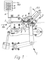
- a device designated as a whole by 1 is used to bend one wholly or partially made of plastic hollow profile 2 and corresponds in structure and mode of operation to what the mechanical parts, such as the device for bending a Hollow profile according to EP 0 318 748 B2 or EP 0 121 873 B1, Figure 1.
- the hollow profile 2 can already during the bending process Desiccant filled or it is then filled with so that it is suitable as a spacer frame for insulating glass panes is. Furthermore, cases are conceivable in which the hollow profile 2 without Desiccant remains.
- This Clamping device 3 has an inner crosspiece 4 of the Hollow profile 2 attacking jaw 5 and one on an outer Crossbar 6 attacking jaw 7 and further is in this area the clamping device 3 also a hold-down 8 for the hollow profile 2 recognizable.
- the device 1 has an overall designated 9 Device for detecting the leg 2a to be bent Hollow profile 2 and an abutment 10 that can be pivoted with it Fix the inside of the resulting bend or curve on.
- the abutment 10 thus acts on the inside of the resulting bend-running inner crossbar 4 of the hollow profile 2.
- a pivotable abutment 10 would also be an abutment according to FIG. 2 of EP 0 121 873 B1 is conceivable.
- the plastic can which is the hollow profile 2, to the extent that they are softened easily deformed without leaving any residual stresses, can also be bent so that after the subsequent Cool the hollow profile 2 has a stable corner. Because this corner is formed in the softened state of the material also exists no risk of bursting or splintering or tearing and in addition, the side webs 11 can be smooth and keep parallel shape and their correct distance so that they later a flat and dense system for the individual panes of one Can form insulating glass.
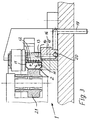
- a hot air heater for the bending area and the abutment 10 is provided.
- the hot air is as effective as possible and without any significant cooling is usable, this includes the hot air channels 12 containing Clamping jaw 5 with its end having the mouths 11 up to or close to the abutment 10, which is especially in the figure 2 is clearly recognizable. Since the abutment 10 during its Inflow with hot air at the same time as one of the bending movements corresponding pivoting or twisting according to the curved arrow Pf2 in Figure 2 is performed during the bending also a correspondingly well-warmed area of the abutment 10 in contact with the inner crosspiece 4 of the hollow profile 2 brought. In addition, the inflowing hot air is on directed the place where the abutment 10 and the inner Cross bar 4 come into contact with each other, so that at this point particularly effective heating can take place.
- a heat exchanger 17 for heating of compressed air flowing in according to arrow Pf3 is used by a corresponding winding line 18 a sufficient dwell time has within the heat exchanger 17 to the desired heating temperature to obtain.
- the heat exchanger 17 can be a block of metal be, which contains heating coils and / or heating elements, which in the Drawing is not shown in detail. From this heat exchanger 17 from the heated compressed air passes through a line 19 to the Clamping device 3 and finally through a conduit 20 to the bore 16, which is in register with the feed opening 13.
- the actual heating process is therefore advantageous outside and at a distance from the bending area of the device 1 performed and it can belong to the device 1 parts be used to bring the hot air to the location to be heated bring so that the bending area is not with additional installations must be provided.
- cooling not shown, for example, by means of cold blown air.
- bending is one Hollow profile 2, which consists entirely or partially of plastic possible in which the bending area of the hollow profile 2 and at least the abutting and effective abutment 10, by which the Hollow profile 2 is bent, at least temporarily before and / or at Bending is heated to a temperature at which the Strength of the material forming or forming the hollow profile is so reduced that the bending process is easy and precise and without the risk of splintering or cracking or tearing open of the hollow profile 2 can take place.
- the hollow profile 2 in Bending range expediently to the softening or plasticizing temperature of the plastic heated and the abutment 10 takes on about the same temperature. This happens because the Bending point and the abutment 10 are blown with hot air, what hot air through the channels and holes already described the clamping devices 3 and thereby their jaw 5 fed become.
- the hot air can already during the feed movement of the Hollow profile 2 are blown into its bending position, so that also one located behind the bending area during bending Part of the hollow profile is at least preheated. It follows thereby a gradual move from the bending point to both sides Temperature transition within the hollow profile 2 so that it does not due to damage due to excessive temperature differences.
- the heated material allows those that occur during bending Compression, elongation, deformation and flow movements without thereby noteworthy voltages and in particular reset voltages stay at the bend. After cooling, the corner of the curved plastic profile 2 high strength and dimensional accuracy.
- a bending device 1 For bending a hollow profile 2, which is made entirely or partially Plastic is used, a bending device 1 with a Define hollow profile 2 during the bending in front of the bending area Clamping device 3 and a device 9 for detecting the in Infeed direction behind leg 2a located behind the bending area, this leg 2a to be bent or part to be bent Hollow profile 2 compared to one inside in the bending area arranged abutment 10 is pivoted and bent. Doing so the bending area of the hollow profile 2 and at least the abutment 10 at least temporarily before and / or when bending to a temperature heated, in which the strength forming the hollow profile 2 Material is reduced so that the bending process easily and can be done precisely and after solidification a stable and true-to-size corner is available. It is particularly suitable for heating good on the inside of the bending point and the abutment 10 directed hot air.
Abstract
Zum Biegen eines Hohlprofiles (2), welches ganz oder teilweise aus Kunststoff besteht, dient eine Biegevorrichtung (1) mit einer das Hohlprofil (2) während des Biegens vor dem Biegebereich festlegenden Spannvorrichtung (3) und einer Einrichtung (9) zum Erfassen des in Zuführrichtung hinter dem Biegebereich befindlichen Schenkels (2a), wobei dieser umzubiegende Schenkel (2a) oder umzubiegende Teil des Hohlprofiles (2) gegenüber einem im Biegebereich innenseitig angeordneten Widerlager (10) verschwenkt und gebogen wird. Dabei wird der Biegebereich des Hohlprofiles (2) und zumindest das Widerlager (10) wenigstens zeitweise vor und/oder beim Biegen auf eine Temperatur aufgeheizt, bei welcher die Festigkeit das Hohlprofil (2) bildenden Werkstoffes vermindert wird, so daß der Biegevorgang leicht und präzise erfolgen kann und nach dem Erstarren eine stabile und maßhaltige Ecke vorhanden ist. Zum Aufheizen eignet sich besonders gut auf die Innenseite der Biegestelle und das Widerlager (10) gerichtete Heißluft. <IMAGE>For bending a hollow profile (2), which consists entirely or partially of plastic, a bending device (1) is used with a clamping device (3) which fixes the hollow profile (2) during the bending in front of the bending area and a device (9) for detecting the in Feed direction behind the bending area (2a), said leg (2a) or part of the hollow profile (2) to be bent being pivoted and bent relative to an abutment (10) arranged on the inside in the bending area. The bending area of the hollow profile (2) and at least the abutment (10) is heated at least temporarily before and / or during bending to a temperature at which the strength of the material forming the hollow profile (2) is reduced, so that the bending process is easy and precise can take place and after solidification there is a stable and dimensionally stable corner. Hot air directed particularly well at the inside of the bending point and the abutment (10) is suitable for heating. <IMAGE>
Description
Die Erfindung betrifft ein Verfahren zum Biegen eines Hohlprofiles, welches ganz oder teilweise aus Kunststoff besteht, wobei zumindest an dem in Gebrauchsstellung außenseitigen Quersteg eine Metallschicht vorgesehen, eingebettet oder außenseitig angeordnet sein kann, zur Herstellung eines insbesondere mit Trockenmittel gefüllten hohlen Abstandhalter-Rahmens für Isolierglasscheiben, wobei das Hohlprofil einer Biegevorrichtung zugeführt und mittels einer Spannvorrichtung in Zuführrichtung vor dem Biegebereich fixiert und der umzubiegende Schenkel des Hohlprofiles in Zuführrichtung hinter dem Biegebereich ebenfalls erfaßt und gegenüber einem im Biegebereich befindlichen Widerlager verschwenkt und gebogen wird.The invention relates to a method for bending a hollow profile, which consists entirely or partially of plastic, at least a metal layer on the crossbar on the outside in the use position can be provided, embedded or arranged on the outside, for Production of a hollow, in particular filled with desiccant Spacer frame for insulating glass panes, the hollow profile fed to a bending device and by means of a clamping device fixed in the feed direction in front of the bending area and the one to be bent Leg of the hollow profile in the feed direction behind the bending area also detected and opposite one located in the bending area Abutment is pivoted and bent.
Die Erfindung betrifft ferner eine Vorrichtung zum Biegen eines ganz oder teilweise aus Kunststoff bestehenden Hohlprofiles zur Herstellung eines insbesondere mit Trockenmittel gefüllten oder zu füllenden hohlen Abstandhalter-Rahmens für Isolierglasscheiben, mit einer etwa in Zuführrichtung des Hohlprofiles vor dem Biegebereich angeordneten Spannvorrichtung, welche zum Erfassen des vor der Biegung oder dem Biegebereich befindlichen Profilbereiches dient und insbesondere eine einerseits an einem inneren Quersteg und andererseits an einem äußeren Quersteg des Hohlprofiles angreifende innere und äußere Klemmbacke oder dergleichen Halterung aufweist, und mit einer Einrichtung zum Erfassen des umzubiegenden Schenkels sowie mit einem Widerlager zum Fixieren der Innenseite der entstehenden Biegung oder Krümmung und/oder des dort verlaufenden inneren Quersteges des Hohlprofiles, welches Widerlager in Gebrauchsstellung im Biegebereich innenseitig angeordnet ist, insbesondere zur Durchführung des vorstehend genannten Verfahrens.The invention further relates to a device for bending a wholly or partially made of plastic hollow profile Production of a filled with desiccant or hollow spacer frames to be filled for insulating glass panes, with an approximately in the feed direction of the hollow profile before Bending area arranged clamping device, which for grasping of the profile area in front of the bend or the bending area serves and especially one on the one hand on an inner Cross bar and on the other hand on an outer cross bar of the hollow profile attacking inner and outer jaw or the like holder has, and with a device for detecting the to be bent Leg as well as with an abutment for fixing the inside the resulting bend or curvature and / or the one running there inner crossbar of the hollow profile, which abutment in Position of use is arranged on the inside in the bending area, in particular to carry out the aforementioned method.
Ein derartiges Verfahren und eine zu seiner Durchführung dienende Vorrichtung, allerdings zum Biegen von aus Metall bestehenden Hohlprofilen ist aus EP 0 121 873 B1 und aus EP 0 318 748 B2 bereits bekannt und hat sich bewährt. Mit den in diesen Patentschriften offenbarten Vorrichtungen wird ein schnelles und exaktes Biegen von metallischen Hohlprofilen, seien sie schon mit Trockenmittel gefüllt oder noch nicht, ermöglicht.Such a method and one used to carry it out Device, however, for bending metal ones Hollow profiles are already known from EP 0 121 873 B1 and from EP 0 318 748 B2 known and has proven itself. With the in these patents disclosed devices is a quick and accurate bending of hollow metal profiles, be it with desiccant filled or not yet.
Es sind inzwischen aber auch Hohlprofile bekannt geworden, die ganz oder teilweise aus Kunststoff bestehen, damit sie eine bessere Isolierung erlauben, also Kältebrücken zwischen den die jeweilige Isolierglasscheibe bildenden Einzelscheiben besser vermeiden, als dies mit metallischen Hohlprofilen und Abstandhalterrahmen möglich ist.In the meantime, however, hollow profiles have also become known or partially made of plastic so they are better Allow insulation, i.e. cold bridges between the respective Avoid single glazing forming single panes better than this is possible with hollow metal profiles and spacer frames is.
Dabei besteht jedoch die Schwierigkeit, daß Kunststoffe beim Biegen nicht die Biege- und Fließeigenschaften wie Metalle haben und deshalb nach den bisher bekannten Verfahren und mit den bisher bekannten Vorrichtungen nicht mit der Präzision und Sicherheit gebogen werden können, die für einen Abstandhalterrahmen erforderlich sind. Ferner besteht die Gefahr, daß bei dem Biegen der Kunststoff bricht oder splittert.However, there is the difficulty that plastics when bending do not have the bending and flow properties like metals and therefore according to the previously known methods and with the previously known Devices are not bent with precision and security that are required for a spacer frame. Further there is a risk that the plastic will break or bend splinters.
Ferner ergibt sich bei aus Kunststoff bestehenden Hohlprofilen der eingangs erwähnten Art das Problem, daß sie nach einem Biegevorgang eine lang anhaltende allmähliche Rückstelltendenz haben, die nicht einem Rückfedern von Metall entspricht, dem durch einen exakten Überbiegungswinkel entgegengewirkt werden kann. Vielmehr neigen solche gebogenen Hohlprofile aus Kunststoff zu einer allmählichen Rückverformung entgegen der vorher durchgeführten Biegung, was während der weiteren Verarbeitung von Abstandhalterrahmen aus derartigen Kunststoff-Hohlprofilen störend ist und zu Abweichungen von den jeweils gewünschten Winkelmaßen führen kann.Furthermore, in the case of hollow profiles made of plastic, the type mentioned the problem that after a bending process have a long lasting gradual reset tendency that is not corresponds to a springback of metal, that of an exact Bending angle can be counteracted. Rather tend such curved plastic hollow profiles to a gradual Recovery against the previously performed bend what during further processing from spacer frames such hollow plastic profiles is bothersome and deviations of the desired angular dimensions.
Es besteht deshalb die Aufgabe, ein Verfahren und eine Vorrichtung der eingangs genannten Art zu schaffen, womit der Vorteil verminderter Kältebrücken durch ganz oder teilweise aus Kunststoff bestehende Hohlprofile beibehalten, diese aber dennoch exakt auf einen gewünschten Winkel gebogen werden können, ohne anschließende Rückstellbewegungen an der Biegestelle in Kauf nehmen zu müssen.There is therefore the task of a method and a device to create of the type mentioned, with the advantage Reduced thermal bridges due to plastic made entirely or partially maintain existing hollow profiles, but still open them exactly a desired angle can be bent without subsequent To have to accept reset movements at the bending point.
Zur Lösung dieser Aufgabe ist das eingangs genannte Verfahren dadurch gekennzeichnet, daß der Biegebereich des Hohlprofiles und/oder zumindest das Widerlager, um welches das Hohlprofil gebogen wird, wenigstens zeitweise vor und/oder beim Biegen auf eine Temperatur aufgeheizt wird, bei welcher die Festigkeit des das Hohlprofil bildenden oder mitbildenden Kunststoffes vermindert wird.The method mentioned at the outset is thereby to achieve this object characterized in that the bending area of the hollow profile and / or at least the abutment around which the hollow profile is bent, at least temporarily before and / or when bending to a temperature is heated at which the strength of the hollow profile forming or co-forming plastic is reduced.
Es ist bekannt, daß Kunststoffe bei entsprechender Erwärmung weich werden und dann problemlos verformt werden können, ohne Rückstellspannungen aufzubauen. Sind sie dann erkaltet, haben sie wieder eine zufriedenstellende Festigkeit. Durch das erfindungsgemäße Verfahren können also die Winkel und Ecken des Abstandhalterrahmens mit der gewünschten Präzision und dabei gleichzeitig mit relativ geringem Kraftaufwand gebogen und auf einen präzisen Biegewinkel eingestellt werden, der nach dem Erkalten des Biegebereiches dann auch die gewünschte Festigkeit hat.It is known that plastics are soft when heated accordingly and can then be easily deformed without restoring stresses build up. If they are cold then they have again a satisfactory strength. By the invention So the angles and corners of the spacer frame can be moved with the desired precision and at the same time with relative bent with little effort and to a precise bending angle can be set, then after the bending area has cooled also has the desired strength.
Besonders zweckmäßig ist es dabei, wenn das Hohlprofil im Biegebereich und zumindest das Widerlager auf die Erweichungs- oder Plazifiziertemperatur des das Hohlprofil bildenden Kunststoffes aufgeheizt wird. Der Biegebereich des Hohlprofiles wird dann so nachgiebig und plastisch, daß die gewünschte exakte Biegung schnell und präzise durchgeführt werden kann, wonach der Kunststoff nach seinem Erkalten dann keinerlei Rückfedertendenzen in die ursprüngliche Lage mehr hat. Dabei macht sich die Erfindung zunutze, daß Kunststoffe in der Regel keinen exakten Schmelzpunkt haben, sondern bei der Erwärmung allmählich immer weicher werden, so daß eine Aufheizung gewählt werden kann, bei der die genannte erleichterte und präzise Biegung gut durchführbar ist, ohne daß das Hohlprofil selbst hinsichtlich seines Querschnittes und seiner Abmessungen im Biegebereich in unerwünschter Weise verformt wird.It is particularly useful if the hollow profile in Bending area and at least the abutment on the softening or Placement temperature of the plastic forming the hollow profile is heated. The bending area of the hollow profile is then so compliant and plastic that the desired exact bend quickly and can be carried out precisely, after which the plastic after his cooling then no tendency to spring back into the original Location has more. The invention makes use of the fact that Plastics generally do not have an exact melting point, but rather gradually become softer when heated, so that a Heating can be chosen in which the said facilitated and precise bending can be carried out without the hollow profile even in terms of its cross section and dimensions is undesirably deformed in the bending area.
Eine besonders zweckmäßige und günstige Verfahrensweise kann dabei darin bestehen, daß die Biegestelle und das Widerlager mit Heißluft angeblasen werden. Dadurch kann eine sehr gezielte und insofern energiesparende Aufheizung durchgeführt werden, ohne daß aufwendige Heizvorrichtungen unmittelbar an der Biegestelle oder an für das Biegen wesentlichen Maschinenteilen installiert werden müssen. Es genügen entsprechende Luftführungen, um eine exakte Zufuhr der Heiß- und Heizluft an die gewünschten Stellen zu ermöglichen. Dabei kann die eigentliche Energiequelle mit der entsprechenden Heizleistung außerhalb des häufig unter beengten Platzverhältnissen befindlichen Biegebereiches angeordnet sein.A particularly expedient and inexpensive procedure can be used consist in that the bending point and the abutment with hot air be blown. This can be a very targeted and insofar energy-saving heating can be carried out without expensive Heaters directly at the bending point or for that Bending essential machine parts must be installed. It appropriate air ducts are sufficient to ensure an exact supply of the hot and To allow hot air to the desired places. It can the actual energy source with the corresponding heating output outside of the often confined space Bending area may be arranged.
Eine weitere Verbesserung des Verfahrens kann vorsehen, daß die Heißluft durch Kanäle oder Bohrungen der Spannvorrichtung zum Fixieren des Hohlprofiles vor der Biegestelle etwa parallel zu dem eingespannten Hohlprofil vor seiner Biegestelle zugeführt und ausgeblasen wird. Dadurch erhält nicht nur die Spannvorrichtung eine Doppelfunktion, sondern es können auch separate Zuführleitungen für die Heißluft vermieden werden. Gleichzeitig kann dadurch die Spannvorrichtung etwas aufgeheizt und vorgeheizt werden, so daß bei dem intermetierenden Betrieb, wie er beim Biegen solcher Abstandhalterrahmen notgedrungen auftritt, weil eine Ecke nach der anderen gebogen werden muß, die zwischendurch unterbrochene Zufuhr der Heißluft nicht dazu führt, daß die erneut eingeschaltete Luft auf ihrem Weg zu der zu beheizenden Stelle unnötig abgekühlt wird. Die erneut eingeschaltete Heißluftzufuhr ergibt, daß die Heizluft dann schon durch eine von dem vorhergehenden Vorgang vorgewärmte Spannvorrichtung zugeführt werden kann und dadurch ihre gewünschte Heiztemperatur behält.A further improvement of the process can provide that the Hot air through channels or holes in the clamping device for Fixing the hollow profile in front of the bending point approximately parallel to the clamped hollow profile in front of its bending point and is blown out. This not only gives the clamping device a double function, but it can also have separate feed lines for the hot air can be avoided. At the same time, the Clamping device to be slightly heated and preheated so that in the intermittent operation, as in the bending of such Spacer frame inevitably occurs because of a corner after the other must be bent, the intermittent supply The hot air does not cause the air to be switched on again is unnecessarily cooled on its way to the point to be heated. The hot air supply switched on again shows that the heating air then already by a preheated from the previous process Clamping device can be supplied and thereby your desired Retains heating temperature.
Für ein gutes Biegeergebnis ist es günstig, wenn der Heißluftstrom etwa in Zuführrichtung des Werkstückes oder Hohlprofiles in den Innenbereich der sich bildenden Biegung und gleichzeitig gegen das Widerlager gerichtet und dadurch die Innenseite der Biegung des Hohlprofiles geheizt wird. Einerseits wird dadurch das Werkstück schon während der Zuführung zur Biegestelle hin etwas vorgeheizt, so daß auch ein Teil des Profiles, der anschließend um das Widerlager herumgebogen wird, erwärmt wird, während andererseits auch das Widerlager oder der Biegedorn selbst und während des eigentlichen Biegevorgangs der vor der Biegung befindliche Teil des Hohlprofiles in ausreichendem Maße beheizt werden, um den Kunststoff soweit zu erweichen, daß eine präzise Formung der Biegung bei gleichzeitiger Beibehaltung der Maßhaltigkeit der Seitenstege zwischen deren Auflagefläche und Niederhalter ermöglicht wird. Die Heißluft kann schon während der Zuführung des Hohlprofiles in Biegeposition, zumindest während des letzten Teiles dieser Zuführung zugeführt und dadurch der hinter und in dem Biegebereich befindliche Teil des Hohlprofiles vorgeheizt werden. Somit sind auch die Nachbarbereiche der eigentlichen Biegung und Biegestelle etwas wärmer und weicher und bilden Übergänge zu dem nicht erweichten oder plastifizierten Teil des Profiles, so daß entsprechende Zug- und/oder Stauchspannungen innerhalb des Werkstoffes des Hohlprofiles aufgenommen und ausgeglichen werden können.For a good bending result, it is beneficial if the hot air flow approximately in the feed direction of the workpiece or hollow profile in the Inside of the bend that forms and at the same time against the Abutment directed and thereby the inside of the bend of the Hollow profile is heated. On the one hand, it becomes the workpiece already preheated during the feeding to the bending point, so that part of the profile, which is then around the abutment is bent around, heated, while on the other hand that too Abutment or the mandrel itself and during the actual Bending process the part of the hollow profile located before the bend are heated to a sufficient extent to the plastic as far soften that precise shaping of the bend while at the same time Maintaining the dimensional accuracy of the side bridges between them Support surface and hold-down is made possible. The hot air can already during the feeding of the hollow profile in the bending position, fed at least during the last part of this feed and thereby the part located behind and in the bending area of the hollow profile are preheated. So the neighboring areas are also the actual bend and bend somewhat warmer and softer and form transitions to the not softened or plasticized part of the profile, so that corresponding tensile and / or Compression stresses within the material of the hollow profile can be absorbed and balanced.
Besonders zweckmäßig ist es, wenn auch die Außenseite des Biegebereiches beheizt, insbesondere mit Heißluft beaufschlagt wird. Dadurch kann auch der beim Biegen zugbeanspruchte Bereich des Hohlprofiles etwas erweicht oder plastifiziert werden, so daß er geschmeidiger wird und der Biegevorgang entsprechend schnell und genau und unter Entfernung von Rückstellspannungen erfolgen kann.It is particularly useful if the outside of the Bending area is heated, in particular with hot air. As a result, the area of the Hollow profile can be softened or plasticized so that it becomes smoother and the bending process correspondingly quick and can be done exactly and with the removal of reset voltages.
Um die Heizluft auf einfache Weise aufheizen und auch mit genügender Strömungsgeschwindigkeit auf dem zu heizenden Biegebereich strömen lassen zu können, kann Preßluft durch einen Wärmetauscher, insbesondere einen elektrisch aufgeheizten Wärmetauscher geleitet und dann als Heißluft zu dem Biegebereich geleitet werden. Preßluft ist praktisch in jedem Betrieb ständig vorhanden, so daß sie einfach abgezweigt oder aber auch aus entsprechenden Preßluftflaschen entnommen werden. Somit werden keine spezielle Kompressoren zur Erzeugung der jeweiligen Preßluft benötigt, die aber auch erforderlichenfalls eingesetzt werden könnten.To heat the heating air in a simple way and also with sufficient Flow rate on the bending area to be heated compressed air through a heat exchanger, in particular an electrically heated heat exchanger and then passed as hot air to the bending area. Compressed air is practically present in practically every establishment, making it easy branched off or from corresponding compressed air bottles be removed. Thus, no special compressors are used Generation of the respective compressed air required, but also could be used if necessary.
Die Erfindung macht sich also bei Anwendung einzelner oder mehrerer der vorbeschriebenen Maßnahmen und Verfahrensschritte die Erkenntnis zu nutze, daß ein ganz oder teilweise aus Kunststoff bestehendes Hohlprofil besonders gut gebogen werden kann, wenn der Biegebereich soweit erwärmt wird, daß die dem Kunststoff eigentlich innewohnenden Spannungen oder Widerstände praktisch beseitigt sind, die sich nach dem Erkalten dann aber wieder einstellen. Somit kann durch das Aufheizen der Biegestelle eine präzise Biegung des Hohlprofiles durchgeführt werden, die anschließend nach dem Erkalten eine entsprechend stabile und maßhaltige Ecke ergibt, so daß insgesamt ein Abstandhalterrahmen aus Kunststoff geschaffen werden kann, der das gewünschte Maß auch in den Ecken und Winkeln beibehält und ein besserer Schutz gegen Wärmeübergang als ein entsprechender metallischer Abstandhalterrahmen ist, also Kältebrücken vermeidet.The invention therefore makes use of one or more the knowledge of the measures and procedural steps described above to use that a completely or partially made of plastic Hollow profile can be bent particularly well if the bending area is heated to the extent that the plastic is actually inherent Tensions or resistances that are practically eliminated then stop cooling again. Thus, through the Heating the bending point a precise bending of the hollow profile be carried out, which then after cooling a accordingly stable and dimensionally stable corner results, so that overall a plastic spacer frame can be created that maintains the desired dimension in the corners and angles better protection against heat transfer than a corresponding one metallic spacer frame is, so avoids cold bridges.
Die eingangs genannte Vorrichtung ist zur Lösung der Aufgabe dadurch gekennzeichnet, daß in Biegebereich zumindest an der Innenseite der Biegung des Hohlprofiles eine Heizung für diesen Biegebereich und/oder für das Widerlager vorgesehen ist. Damit kann der Biegebereich so aufgeheizt werden, daß ein ganz oder teilweise aus Kunststoff bestehendes Hohlprofil hinsichtlich seines Werkstoffes weicher und nachgiebiger wird und problemlos gebogen werden kann, ohne daß durch diesen Biegevorgang Rückstellspannungen oder Rückstelltendenzen zurückbleiben. Nach dem Erkalten ist eine solche Biegestelle stabil und dauerhaft.The device mentioned at the outset is for achieving the object characterized in that in the bending area at least on the inside the bending of the hollow profile a heater for this bending area and / or is provided for the abutment. So that the Bending area to be heated so that a whole or part of it Plastic existing hollow profile with regard to its material becomes softer and more flexible and can be easily bent, without restoring voltages or Reset trends remain. After the cold is one Bending point stable and permanent.
Besonders günstig ist es dabei, wenn eine Heißluft-Heizung für den Biegebereich und das Widerlager vorgesehen ist. Mittels Heißluft kann das Aufheizen sowohl hinsichtlich der Temperatur als auch in räumlicher Hinsicht genau erfolgen, ohne daß innerhalb der Biegevorrichtung oder dem Widerlager spezielle Heizgeräte oder Heizeinrichtungen eingebaut werden müßten. Heißluft läßt sich sehr einfach und gezielt zuführen.It is particularly favorable if a hot air heater for the Bending area and the abutment is provided. Using hot air can the heating both in terms of temperature and in spatially accurate, without that within the Bending device or the abutment special heaters or Heating devices would have to be installed. Hot air can be very simple and targeted feeding.
Besonders günstig ist es bei einer derartigen Vorrichtung, wenn ein oder mehrere Mündungen von Heißluft-Kanälen auf die Biegestelle, insbesondere die Innenseite und/oder die Außenseite der Biegung und auf das Widerlager gerichtet sind. Dadurch können exakt die Stellen und Teile beheizt werden, die für die Verformung des Hohlprofiles beim Biegen besonders wichtig sind, während sonstige Bereiche unbeheizt bleiben können.With such a device, it is particularly favorable if one or more mouths of hot air ducts on the bending point, especially the inside and / or the outside of the bend and are aimed at the abutment. This allows exactly that Places and parts are heated that are responsible for the deformation of the Hollow sections are particularly important when bending, while others Areas can remain unheated.
Zumindest die an dem die spätere Innenseite des Abstandhalter-Rahmens bildenden inneren Quersteg angreifende innere Klemmbacke oder dergleichen Halterung oder Anlage der vor dem Biegebereich befindlichen Spannvorrichtung kann den oder die Luftkanäle für die Heiz- und Heißluft enthalten, die mit ihrer Mündung auf den Biegebereich und insbesondere die Innenseite der Biegung und das Widerlager gerichtet sind. Dadurch erhält die Spannvorrichtung und insbesondere deren innere Klemmbacke oder Halterung oder Anlage für das Profil eine zusätzliche Funktion als Führung und Leitung für die Heißluft. Ferner kann dadurch die das Hohlprofil vor dem Biegebereich haltende Spannvorrichtung und insbesondere ihre an der Innenseite des Hohlprofiles anliegende Klemmbacke oder Halterung von der zugeführten Heißluft durchströmt und dadurch erwärmt werden, so daß der Werkstoff des Hohlprofiles von der beheizten Biegestelle ausgehend auch nach den Seiten hin noch etwas erwärmt ist und sich so ein allmählicher Übergang zum kalten Teil und Bereich des Hohlprofiles ergibt. Ferner wird dadurch erreicht, daß nach einer Unterbrechung der Heißluftzufuhr, beispielsweise nach einem erneuten Vorschub des Hohlprofiles die dann wieder eingeschaltete Heißluft durch eine bereits vorgewärmte Spannvorrichtung strömt und dort nicht wieder abkühlt, so daß auch die Bearbeitungsgeschwindigkeit trotz der beim Vorschieben von einem zum nächsten Biegebereich erfolgenden Unterbrechung nicht verzögert wird. Die Wärmekapazität der Spannvorrichtung reicht aus, um ein zu starkes Abkühlen während einer solchen Unterbrechung zu vermeiden, so daß die dann wieder eingeschaltete Heißluft praktisch sofort die erforderliche Heiztemperatur hat.At least that on which the later inside of the spacer frame forming inner crossbar attacking inner jaw or the same bracket or system in front of the bending area located jig can or the air channels for the Heating and hot air contain, with their mouth on the Bending area and especially the inside of the bend and that Abutments are directed. This gives the jig and in particular the inner jaw or holder or system for the profile an additional function as leadership and management for the hot air. Furthermore, the hollow profile in front of the Bending area holding fixture and especially their on clamping jaw or holder lying on the inside of the hollow profile flowed through by the supplied hot air and thereby heated, so that the material of the hollow profile from the heated bending point starting from the sides is still a little warmed up and such a gradual transition to the cold part and area of the Hollow profile results. It is also achieved that after a Interruption of the hot air supply, for example after a new one Feeding the hollow profile the hot air then switched on again flows through a preheated tensioning device and there does not cool down again, so that the processing speed despite that when advancing from one bending area to the next interruption is not delayed. The heat capacity the clamping device is sufficient to cool down too much during to avoid such an interruption, so that then again switched on hot air almost immediately the required Heating temperature.
Günstig ist es, wenn mehrere parallele Luftkanäle insbesondere nahe der dem Hohlprofil zugewandten Oberfläche der inneren Klemmbacke angeordnet sind und in Zuführrichtung des Hohlprofiles verlaufen und wenn die diese Heißluftkanäle enthaltende Klemmbacke oder dergleichen mit ihrem die Mündungen der Luftkanäle oder Bohrungen aufweisenden Ende bis an oder nah an das Widerlager reicht. Dadurch kann einerseits eine gute Abstützung des Hohlprofiles vor dem Biegebereich erzielt und andererseits vermieden werden, daß die Heißluft über eine zu große Strecke durch die freie Atmosphäre geblasen werden muß und dabei zuviel Wärme verlieren könnte.It is expedient if several parallel air ducts are particularly close the surface of the inner jaw facing the hollow profile are arranged and extend in the feed direction of the hollow profile and if the clamping jaw containing these hot air ducts or the like with their the mouths of the air channels or holes having end up to or close to the abutment. Thereby can on the one hand good support of the hollow profile before Bending range achieved and on the other hand avoided that the Hot air over a long distance through the free atmosphere must be blown and lose too much heat.
Eine weitere zweckmäßige Ausgestaltung der erfindungsgemäßen Vorrichtung kann darin bestehen, daß die Klemmbacke oder dergleichen eine quer zu den insbesondere als Bohrung ausgebildeten Heißluftkanälen orientierte, mit diesen verbundene Zuführöffnung für die Heißluft hat und über eine Koppelung mit einer Halterung verbunden ist, in welcher eine Bohrung oder ein Kanal für die Heißluftzufuhr angeordnet ist, die in Gebrauchsstellung mit der Zuführöffnung der Klemmbacke oder dergleichen ganz oder zumindest teilweise in Überdeckung ist und daß die Klemmbacke gegebenenfalls zur Anpassung an unterschiedliche Abmessungen der zu biegenden Hohlprofile austauschbar ist. Ist die Klemmbacke beschädigt oder soll ein Hohlprofil anderer Breite gebogen werden, kann sie also auf einfache Weise gegen eine neue oder anders bemessene Klemmbacke ausgetauscht werden, deren Zuführöffnung dann in Überdeckung mit der Bohrung oder dem Kanal für die Heißluftzufuhr gelangt, so daß es keiner besonderen Maßnahmen bedarf, wenn ein breiteres oder schmaleres Hohlprofil gebogen werden muß als die Klemmbacke als solche aus ihrer Halterung zu entnehmen und durch eine entsprechend bemessene andere Klemmbacke zu ersetzen.Another useful embodiment of the invention Device can be that the jaw or the like a transverse to the hot air channels, in particular, formed as a bore oriented feed opening for the hot air has and a coupling with a bracket is connected, in which a bore or a channel for the Hot air supply is arranged, which is in the use position with the Feed opening of the clamping jaw or the like completely or at least is partially in overlap and that the jaw may be to adapt to different dimensions of the to be bent Hollow profiles is interchangeable. Is the jaw damaged or if a hollow profile of a different width is to be bent, it can in a simple way against a new or differently dimensioned clamping jaw are exchanged, the feed opening then overlap with the hole or duct for the hot air supply arrives so that no special measures are required if a wider or narrower hollow profile must be bent than the jaw as remove them from their holder and by a corresponding to replace the other sized jaw.
Die insbesondere als Bohrungen ausgebildeten parallelen Einzelkanäle können für eine gleichmäßige Temperaturverteilung hinter der Anlagefläche der Klemmbacke etwa gleichmäßig verteilt angeordnet sein. Damit wird nicht nur die Klemmbacke gleichmäßig vorgeheizt, sondern vor allem auch im Biegebereich eine gleichmäßige Heizung über die gesamte Breite des innenliegenden Quersteges des Hohlprofiles und des dort befindlichen Widerlagers erzielt. Dadurch können unterschiedliche Temperaturen im Biegebereich vermieden werden, die unter Umständen zu unterschiedlichen Biegeergebnissen über die Breite des Quersteges führen könnten. Entsprechend genau und exakt ist die erzielte Biegung und ihr Winkel über die gesamte Breite des Hohlprofiles und des dadurch gebildeten Abstandhalterrahmens.The parallel individual channels, in particular designed as bores for an even temperature distribution behind the Contact surface of the jaw arranged approximately evenly distributed his. This not only preheats the jaw evenly, but above all, even heating in the bending area over the entire width of the internal crosspiece of the Hollow profile and the abutment located there. Thereby can avoid different temperatures in the bending area that may lead to different bending results could lead across the width of the crossbar. Accordingly, exactly and the bend achieved and its angle over the entire is exact Width of the hollow profile and the spacer frame formed thereby.
Weitere Ausgestaltungen der erfindungsgemäßen Vorrichtung sind Gegenstand weiterer Ansprüche.Further configurations of the device according to the invention are Subject of further claims.
Anspruch 17 enthält Merkmale und Maßnahmen betreffend das Aufheizen
der Heißluft mit Hilfe eines Wärmetauschers, der bevorzugt als
Metall- oder Aluminiumblock mit entsprechenden Kanälen und
Heizelementen gestaltet sein kann.
Anspruch 18 betrifft die Möglichkeit, an der Außenseite der
Biegestelle das ganz oder teilweise aus Kunststoff bestehende
Hohlprofil während des Biegevorganges in einer Weise zu bearbeiten,
wie es aus EP 0 318 748 B2 und aus EP 0 121 873 B1 bekannt ist,
wobei es dabei wiederum besonders günstig ist, wenn der Biegebereich
und dabei speziell auch die Außenseite des Biegebereiches beheizt
wird.
Anspruch 19 betrifft eine in Vorschubrichtung hinter dem Biegebereich
angeordnete Kühlung, durch die die Erweichung des Kunststoffes nach
dem Biegevorgang möglichst schnell rückgängig gemacht werden kann.
Anspruch 20 gibt dabei eine konstruktive Möglichkeit an, wie die
zum Erzeugen der Heißluft dienende Preßluft auch als Kühlluft nutzbar
gemacht werden kann.
Insgesamt werden ein Verfahren und eine Vorrichtung vorgeschlagen, womit an sichbisher schonbekannte Biegeverfahren und -vorrichtungen für aus Metall bestehende Hohlprofile auch für solche, die ganz oder teilweise aus Kunststoff bestehen, nutzbar gemacht werden können, in dem zusätzlich der Biegebereich in der beschriebenen Weise gezielt soweit aufgeheizt wird, daß der Kunststoff des Hohlprofiles der Verformung beim Biegen keinen oder keine nennenswerten Widerstand entgegensetzt, aber seine Querschnittsform und Abmessung, insbesondere bezüglich der Breite und der Parallelität der als Anlage für die Einzelscheiben dienenden Seitenstege beibehält.Overall, a method and a device are proposed with what are already known bending processes and devices for hollow profiles made of metal also for those that are or partially made of plastic, can be used can, in addition to the bending range described in the Way is specifically heated so far that the plastic of the Hollow profile of the deformation when bending no or none opposes significant resistance, but its cross-sectional shape and dimensions, particularly with regard to width and parallelism the side bars serving as an attachment for the individual panes maintains.
Nachstehend ist ein Ausführungsbeispiel der Erfindung anhand der Zeichnung näher beschrieben. Es zeigt in zum Teil schematisierter Darstellung:
- Fig.1
- eine Draufsicht einer erfindungsgemäßen Vorrichtung zum Biegen eines zumindest aus Kunststoff bestehenden Hohlprofiles mit einer vor dem Biegebereich angeordneten Spannvorrichtung, einem an der Innenseite des Biegebereiches angeordneten, im Ausführungsbeispiel mit der Biegebewegung mitschwenkbaren Widerlager und mit einer Einrichtung zum Erfassen des umzubiegenden Schenkels, wobei das Hohlprofil teilweise gebogen ist, seine Ausgangsstellung und seine Endstellung aber auch mit unterbrochenen Linien angedeutet sind,
- Fig.2
- in vergrößertem Maßstab den Biegebereich mit dem Widerlager und einem Teilschnitt durch eine Klemmbacke der Spannvorrichtung im Bereich eines auch das Widerlager und die Innenseite der Biegung gerichteten Heißluft-Kanales sowie
- Fig.3
- einen Querschnitt der Vorrichtung und des zu biegenden Hohlprofiles im Bereich der Zufuhr der Heiz- und Heißluft und vor dem Biegebereich.
- Fig. 1
- a plan view of a device according to the invention for bending an at least plastic hollow profile with a clamping device arranged in front of the bending area, an abutment arranged on the inside of the bending area, in the exemplary embodiment also pivotable with the bending movement, and with a device for detecting the leg to be bent, the hollow profile partially is curved, but its starting position and end position are also indicated with broken lines,
- Fig. 2
- on an enlarged scale the bending area with the abutment and a partial section through a clamping jaw of the tensioning device in the area of a hot air duct also directed towards the abutment and the inside of the bend and
- Fig. 3
- a cross section of the device and the hollow profile to be bent in the area of the supply of hot and hot air and in front of the bending area.
Eine im ganzen mit 1 bezeichnete Vorrichtung dient zum Biegen eines
ganz oder teilweise aus Kunststoff bestehenden Hohlprofiles 2 und
entspricht in ihrem Aufbau und in ihrer Wirkungsweise, was die
mechanischen Teile betrifft, etwa der Vorrichtung zum Biegen eines
Hohlprofiles gemäß EP 0 318 748 B2 oder EP 0 121 873 B1, Figur 1.A device designated as a whole by 1 is used to bend one
wholly or partially made of plastic
Das Hohlprofil 2 kann dabei schon während des Biegevorganges mit
Trockenmittel gefüllt sein oder es wird anschließend damit gefüllt,
damit es als Abstandhalter-Rahmen für Isolierglasscheiben geeignet
ist. Ferner sind Fälle denkbar, in denen das Hohlprofil 2 ohne
Trockenmittel bleibt.The
In den Figuren 1 und 2 erkennt man deutlich den Biegebereich, in
welchem das Hohlprofil 2 durch den Biegevorgang gekrümmt wird und
in Figur 1 und 2 eine Teilkrümmung aufweist. Mit strichpunktierten
Linien ist dabei auch der ursprünglich gestreckte Zustand sowie
der um einen rechten Winkel gebogene Endzustand dargestellt. Es
können aber auch andere als rechte Winkel erzeugt werden.In Figures 1 and 2 you can clearly see the bending area, in
which the
In Zuführrichtung des Hohlprofiles 2 vor diesem Biegebereich ist
eine Spannvorrichtung 3 zum Erfassen des vor der Biegung oder dem
Biegebereich befindlichen Teiles des Profiles 2 vorgesehen, womit
also das Profil 2 während des Biegevorganges fixiert wird. Diese
Spannvorrichtung 3 hat eine an einem inneren Quersteg 4 des
Hohlprofiles 2 angreifende Klemmbacke 5 und eine an einem äußeren
Quersteg 6 angreifende Klemmbacke 7 und ferner ist in diesem Bereich
der Spannvorrichtung 3 auch ein Niederhalter 8 für das Hohlprofil
2 zu erkennen.Is in the feed direction of the
Ferner weist die Vorrichtung 1 eine im ganzen mit 9 bezeichnete
Einrichtung zum Erfassen des umzubiegenden Schenkels 2a des
Hohlprofiles 2 und ein damit mitschwenkbares Widerlager 10 zum
Fixieren der Innenseite der entstehenden Biegung oder Krümmung auf.
Das Widerlager 10 beaufschlagt also den dort an der Innenseite der
entstehenden Biegungverlaufenden inneren Quersteg 4 des Hohlprofiles
2. Anstelle eines solchen mitschwenkbaren Widerlagers 10 wäre auch
ein Widerlager gemäß Figur 2 der EP 0 121 873 B1 denkbar.Furthermore, the device 1 has an overall designated 9
Device for detecting the leg 2a to be bent
Im Biegebereich ist im Ausführungsbeispiel an der Innenseite der
Biegung des Hohlprofiles 2, also im Bereich seines inneren Quersteges
4, eine im folgenden näher zu beschreibende Heizung für den
Biegebereich des Hohlprofiles selbst und für das Widerlager 10
vorgesehen. Mit einer solchen Heizung kann der Kunststoff, aus
welchem das Hohlprofil 2 besteht, soweit erweicht werden, daß er
leicht und ohne Hinterlassung von Rückstellspannungen verformt,
also auch gebogen werden kann, so daß nach dem anschließenden
Erkalten das Hohlprofil 2 eine stabile Ecke aufweist. Da diese Ecke
in erweichtem Zustand des Werkstoffes gebildet wird, besteht auch
nicht die Gefahr eines Aufplatzens oder Splittern oder Reißens und
darüber hinaus können auch die Seitenstege 11 ihre glatte und
parallele Form und ihren korrekten Abstand behalten, so daß sie
später eine ebene und dichte Anlage für die Einzelscheiben einer
Isolierglasscheibe bilden können.In the bending area in the exemplary embodiment is on the inside
Bending of the
Im Ausführungsbeispiel ist eine Heißluft-Heizung für den Biegebereich
und das Widerlager 10 vorgesehen. Dazu sind mehrere Mündungen 11
(Fig. 2) von Heißluftkanälen 12 (Fig. 3) auf die Biegestelle, nämlich
die Innenseite der Biegung, und auf das Widerlager 10 gerichtet.
Dies wird besonders deutlich anhand der Figur 2 in welcher ein
derartiger Heißluftkanal 12 mit seiner gegen das Widerlager 10
gerichteten Mündung 11 im Längsschnitt deutlich erkennbar ist.In the exemplary embodiment is a hot air heater for the bending area
and the
Dabei enthält die an dem die spätere Innenseite des Abstandhalterrahmens
bildenden inneren Quersteg 4 angreifende innere Klemmbacke
5 der in Zuführrichtung des Hohlprofiles 2 vor dem Biegebereich
befindliche Spannvorrichtung 3 diese Luftkanäle 12 für die Heiz- und
Heißluft, die alle mit ihrer Mündung 11 auf den Biegebereich
und die Innenseite der Biegung und das Widerlager 10 gerichtet sind.
Anhand der Figur 3 wird deutlich, daß auf diese Weise Heißluft über
die gesamte Querschnittserstreckung des inneren Quersteges 4 und
somit auch über die gesamte Höhe des Widerlagers 10 zugeführt wird
und eine gleichmäßige Erwärmung beziehungsweise Aufheizung bewirkt.
Dabei sind mehrere parallele Luftkanäle 12 nahe der dem Hohlprofil
2 zugewandten Oberfläche der inneren Klemmbacke 5 angeordnet und
verlaufen in der in Figur 1 durch den Pfeil Pf1 angedeuteten
Zuführrichtung des Hohlprofiles 2. Auch die Heißluft strömt also
in dieser Richtung, bevor sie nach dem Austritt aus den Mündungen
11 auf das Widerlager 10 und den inneren Bereich der Biegung und
dort vor allem den inneren Quersteg 4 des Hohlprofiles 2 trifft.The contains the later inside of the spacer frame
forming inner crossbar 4 attacking
Damit die Heißluft möglichst effektiv und ohne nennenswerte Abkühlung
nutzbar wird, reicht diese die Heißluftkanäle 12 enthaltende
Klemmbacke 5 mit ihrem die Mündungen 11 aufweisenden Ende bis an
beziehungsweise nahe an das Widerlager 10, was vor allem in Figur
2 deutlich erkennbar ist. Da das Widerlager 10 während seiner
Anströmung mit Heißluft gleichzeitig eine der Biegebewegung
entsprechende Verschwenkung oder Verdrehung entsprechend dem
gekrümmten Pfeil Pf2 in Figur 2 durchführt, wird während des Biegens
auch ständig ein entsprechend gut erwärmter Bereich des Widerlagers
10 mit dem innenliegenden Quersteg 4 des Hohlprofiles 2 in Kontakt
gebracht. Drüber hinaus wird dadurch die anströmende Heißluft an
die Stelle geleitet, wo das Widerlager 10 und der innenliegende
Quersteg 4 miteinander in Berührung kommen, so daß an dieser Stelle
eine besonders effektive Aufheizung erfolgen kann.So that the hot air is as effective as possible and without any significant cooling
is usable, this includes the
Bei gleichzeitiger Betrachtung der Figuren 2 und 3 erkennt man,
daß die die Kanäle 12 enthaltende Klemmbacke 5 eine quer zu den
als Bohrungen ausgebildeten Heißluftkanälen 12 orientierte, mit
diesen verbundene Zuführöffnung 13 mit relativ großem Durchmesser
hat und über eine Koppelung 14 mit einer Halterung 15 verbunden
ist, in welcher eine Bohrung 16 oder ein Kanal für die Heißluftzufuhr
mit etwas kleinerem Durchmesser angeordnet ist, die in Gebrauchsstellung
mit der Zuführöffnung 13 der Klemmbacke 5 gemäß Figur 1
und 2 in Überdeckung ist. Die Klemmbacke 5 kann dabei leicht
ausgetauscht und ausgewechselt werden, um zum Beispiel eine Anpassung
an unterschiedlich breite Hohlprofile 2 zu ermöglichen. Wichtig
ist nur, daß jede jeweils austauschbare Klemmbacke 5 die entsprechende
Zuführöffnung 13 hat, die die Bohrung oder den Kanal
16 in Gebrauchsstellung überdeckt, so daß die zuströmende Heißluft
in die Kanäle 12 gelangt. Dabei sind diese als Bohrungen ausgebildeten
parallelen Heißluftkanäle 12 für eine gleichmäßige
Temperaturverteilung hinter der Anlagefläche der Klemmbacke 5 etwa
gleichmäßig verteilt angeordnet, haben also untereinander und von
dem anliegenden Hohlprofil 2 beziehungsweise der entsprechenden
Anlagefläche der Klemmbacke 5 jeweils gleiche Abstände. Außerdem
haben sie übereinstimmende Durchmesser, wobei aber die Gesamtquerschnittsfläche
der Heißluftkanäle 12 kleiner als der Querschnitt
der Zuführöffnung 13 ist, so daß die zuströmende Heißluft gleichmäßig
auf alle Kanäle 12 verteilt wird.When looking at Figures 2 and 3 at the same time, you can see
that the
In Figur 1 ist ein Wärmetauscher 17 angedeutet, der zum Aufheizen
von gemäß dem Pfeil Pf3 zuströmender Preßluft dient, die durch eine
entsprechende gewundene Leitung 18 eine ausreichende Verweilzeit
innerhalb des Wärmetauschers 17 hat, um die gewünschte Heiztemperatur
zu erhalten. Der Wärmetauscher 17 kann dabei ein Block aus Metall
sein, welcher Heizspiralen und/oder Heizstäbe enthält, was in der
Zeichnung nicht näher dargestellt ist. Von diesem Wärmetauscher
17 aus gelangt die erhitzte Preßluft über eine Leitung 19 zu der
Spannvorrichtung 3 und durch einen Leitungskanal 20 schließlich
zu der Bohrung 16, die in Überdeckung mit der Zuführöffnung 13 ist.In Figure 1, a
In vorteilhafter Weise wird also der eigentliche Heizvorgang außerhalb und mit Abstand zum Biegebereich der Vorrichtung 1 durchgeführt und es können zur Vorrichtung 1 gehörende Teile mitbenutzt werden, um die Heißluft an die zu beheizende Stelle zu bringen, so daß der Biegebereich nicht mit zusätzlichen Installationen versehen werden muß.The actual heating process is therefore advantageous outside and at a distance from the bending area of the device 1 performed and it can belong to the device 1 parts be used to bring the hot air to the location to be heated bring so that the bending area is not with additional installations must be provided.
An der Außenseite der Biegestelle erkennt man im Ausführungsbeispiel
noch ein unter Anpreßdruck relativ zu dem Widerlager 10 und dem
Hohlprofil 2 bewegbares und an die Außenseite des Profiles 2
anpreßbares werkzeug in Form einer Druckrolle 21, die gemäß Figur
3 schmaler als das Hohlprofil 2 ist, so daß sie unter Beaufschlagung
des äußeren Quersteges 6 zwischen die Seitenstege 11 des Hohlprofiles
2 eintauchen kann, wie es aus EP 0 318 748 B2 bekannt ist. Dies
ist besonders dann zweckmäßig, wenn in dem äußeren Quersteg 6 eine
Metalleinlage vorgesehen ist oder dieser Steg 6 aus Metall besteht.On the outside of the bending point can be seen in the embodiment
still one under contact pressure relative to the
Hinter dem Biegebereich kann eine nicht näher dargestellte Kühlung, beispielsweise mittels kalter Blasluft vorgesehen sein. Dies könnte durch Zuleitung von Preßluft geschehen, wobei in Strömungsrichtung der Preßluft gesehen vor der Heizvorrichtung und dem Wärmetauscher 17 eine Abzweigung für die Preßluft angeordnet wird, durch welche kühle Preßluft in den Bereich des Hohlprofiles hinter der Biegestelle geleitet werden kann. Entsprechend schnell kann das zunächst unter Erwärmung verformte Hohlprofil wieder zum Erkalten und Erstarren gebracht werden, so daß es die erforderliche Steifheit und Stabilität auch im Biegebereich erhält.Behind the bending area, cooling, not shown, for example, by means of cold blown air. this could done by supplying compressed air, being in the direction of flow the compressed air seen in front of the heater and the heat exchanger 17 a branch for the compressed air is arranged, through which cool compressed air in the area of the hollow profile behind the bending point can be directed. This can be done quickly under Heating deformed hollow profile again for cooling and solidification brought so that it has the required rigidity and stability also in the bending area.
Mit der vorbeschriebenen Vorrichtung ist also ein Biegen eines
Hohlprofiles 2, welches ganz oder teilweise aus Kunststoff besteht
möglich, in dem der Biegebereich des Hohlprofiles 2 und zumindest
das dort anliegende und wirksame Widerlager 10, um welches das
Hohlprofil 2 gebogen wird, wenigstens zeitweise vor und/oder beim
Biegen auf eine Temperatur aufgeheizt wird, bei welcher die
Festigkeit des das Hohlprofil bildenden oder mitbildenden Werkstoffes
so vermindert wird, daß der Biegevorgang leicht und präzise und
ohne die Gefahr eines Splitterns oder Aufplatzens oder Aufreißens
des Hohlprofiles 2 erfolgen kann. Dabei wird das Hohlprofil 2 im
Biegebereich zweckmäßigerweise auf die Erweichungs- oder Plastizifiertemperatur
des Kunststoffes aufgeheizt und das Widerlager 10
nimmt etwa dieselbe Temperatur an. Dies geschieht dadurch, daß die
Biegestelle und das Widerlager 10 mit Heißluft angeblasen werden,
welche Heißluft durch die schon beschriebenen Kanäle und Bohrungen
der Spannvorrichtungen 3 und dabei ihrer Klemmbacke 5 zugeführt
werden.With the device described above, bending is one
Dabei kann die Heißluft schon während der Zuführbewegung des
Hohlprofiles 2 in seine Biegeposition ausgeblasen werden, so daß
auch ein während des Biegens hinter dem Biegebereich befindlicher
Teil des Hohlprofiles zumindest vorgeheizt wird. Es ergibt sich
dadurch von der Biegestelle nach beiden Seiten ein allmählicher
Temperaturübergang innerhalb des Hohlprofiles 2, so daß es nicht
durch Beschädigungen aufgrund zu großer Temperaturunterschiede kommt.
Das aufgeheizte Material erlaubt dabei die beim Biegen auftretenden
Stauchungen, Längungen, Verformungen und Fließbewegungen, ohne daß
dadurch nennenswerte Spannungen und insbesondere Rückstellspannungen
an der Biegung zurückbleiben. Nach dem Erkalten hat die Ecke des
gebogenen Kunststoffprofiles 2 eine hohe Festigkeit und Maßhaltigkeit.The hot air can already during the feed movement of the
Zum Biegen eines Hohlprofiles 2, welches ganz oder teilweise aus
Kunststoff besteht, dient eine Biegevorrichtung 1 mit einer das
Hohlprofil 2 während des Biegens vor dem Biegebereich festlegenden
Spannvorrichtung 3 und einer Einrichtung 9 zum Erfassen des in
Zuführrichtung hinter dem Biegebereich befindlichen Schenkels 2a,
wobei dieser umzubiegende Schenkel 2a oder umzubiegende Teil des
Hohlprofiles 2 gegenüber einem im Biegebereich innenseitig
angeordneten Widerlager 10 verschwenkt und gebogen wird. Dabei wird
der Biegebereich des Hohlprofiles 2 und zumindest das Widerlager
10 wenigstens zeitweise vor und/oder beim Biegen auf eine Temperatur
aufgeheizt, bei welcher die Festigkeit das Hohlprofil 2 bildenden
Werkstoffes vermindert wird, so daß der Biegevorgang leicht und
präzise erfolgen kann und nach dem Erstarren eine stabile und
maßhaltige Ecke vorhanden ist. Zum Aufheizen eignet sich besonders
gut auf die Innenseite der Biegestelle und das Widerlager 10
gerichtete Heißluft.For bending a
Claims (19)
Applications Claiming Priority (2)
| Application Number | Priority Date | Filing Date | Title |
|---|---|---|---|
| DE19839444 | 1998-08-29 | ||
| DE1998139444 DE19839444C1 (en) | 1998-08-29 | 1998-08-29 | Bending metal-coated plastic hollow profile containing drying agent, forming double-glazing spacer frame |
Publications (2)
| Publication Number | Publication Date |
|---|---|
| EP0983809A2 true EP0983809A2 (en) | 2000-03-08 |
| EP0983809A3 EP0983809A3 (en) | 2000-10-04 |
Family
ID=7879186
Family Applications (1)
| Application Number | Title | Priority Date | Filing Date |
|---|---|---|---|
| EP99116593A Withdrawn EP0983809A3 (en) | 1998-08-29 | 1999-08-25 | Method and device for bending a hollow profile for making a spacer frame for insulating glazing |
Country Status (2)
| Country | Link |
|---|---|
| EP (1) | EP0983809A3 (en) |
| DE (1) | DE19839444C1 (en) |
Cited By (1)
| Publication number | Priority date | Publication date | Assignee | Title |
|---|---|---|---|---|
| FR3074434A1 (en) * | 2017-12-06 | 2019-06-07 | Meca Theil | INSTALLATION AND METHOD FOR FOLDING METAL SHEET PROFILES |
Families Citing this family (4)
| Publication number | Priority date | Publication date | Assignee | Title |
|---|---|---|---|---|
| AT410909B (en) * | 2000-05-09 | 2003-08-25 | Lisec Peter | Hollow strip bending process involves supporting hollow strip both internally and externally during bending |
| DE50100881D1 (en) * | 2001-08-20 | 2003-12-04 | Peter Lisec | Method and device for bending hollow profile strips to form spacer frames for insulating glass panes |
| AT514109B1 (en) * | 2013-04-12 | 2015-02-15 | Progress Maschinen & Automation Ag | bending machine |
| CA2924182C (en) * | 2015-04-02 | 2022-12-06 | Lombarda Macchine S.A.S. Di G.B. Lattuada & C. | Method for automatically bending spacer elements for insulating glass panes - double glazings and machine for carrying out the method |
Citations (2)
| Publication number | Priority date | Publication date | Assignee | Title |
|---|---|---|---|---|
| EP0121873A2 (en) | 1983-04-09 | 1984-10-17 | Franz Xaver Bayer Isolierglasfabrik KG | Method and apparatus for bending spacekeeping profiles for thermopane glasses |
| EP0318748B1 (en) | 1987-12-03 | 1992-09-02 | Franz Xaver Bayer Isolierglasfabrik KG | Apparatus for bending a hollow profile, in particular a frame of spacekeeping profiles for insulating glass panes |
Family Cites Families (5)
| Publication number | Priority date | Publication date | Assignee | Title |
|---|---|---|---|---|
| JPS5942919A (en) * | 1982-09-03 | 1984-03-09 | Toyama Kogyo Kk | Bending device for thermoplastic resin strip |
| CA1246978A (en) * | 1983-04-09 | 1988-12-20 | Franz Bayer | Method of and apparatus for making spacers for use in multiple-pane windows of the like |
| DE3542461A1 (en) * | 1985-11-30 | 1987-06-04 | Ewald Bous | Plastic-pipe preheating unit |
| US5630306A (en) * | 1996-01-22 | 1997-05-20 | Bay Mills Limited | Insulating spacer for creating a thermally insulating bridge |
| FR2774625B1 (en) * | 1998-02-10 | 2000-03-10 | Seva | PROCESS FOR FOLDING PROFILES COMPRISING A HOLLOW BODY AND A COATING SHEET, AND PROFILE FOLDED THEREBY |
-
1998
- 1998-08-29 DE DE1998139444 patent/DE19839444C1/en not_active Expired - Fee Related
-
1999
- 1999-08-25 EP EP99116593A patent/EP0983809A3/en not_active Withdrawn
Patent Citations (2)
| Publication number | Priority date | Publication date | Assignee | Title |
|---|---|---|---|---|
| EP0121873A2 (en) | 1983-04-09 | 1984-10-17 | Franz Xaver Bayer Isolierglasfabrik KG | Method and apparatus for bending spacekeeping profiles for thermopane glasses |
| EP0318748B1 (en) | 1987-12-03 | 1992-09-02 | Franz Xaver Bayer Isolierglasfabrik KG | Apparatus for bending a hollow profile, in particular a frame of spacekeeping profiles for insulating glass panes |
Cited By (2)
| Publication number | Priority date | Publication date | Assignee | Title |
|---|---|---|---|---|
| FR3074434A1 (en) * | 2017-12-06 | 2019-06-07 | Meca Theil | INSTALLATION AND METHOD FOR FOLDING METAL SHEET PROFILES |
| EP3495067A1 (en) * | 2017-12-06 | 2019-06-12 | Méca Theil | Device and method for bending wing metal profiles |
Also Published As
| Publication number | Publication date |
|---|---|
| EP0983809A3 (en) | 2000-10-04 |
| DE19839444C1 (en) | 2000-01-05 |
Similar Documents
| Publication | Publication Date | Title |
|---|---|---|
| EP0456121B1 (en) | Method of bending plate-like workpieces and bending machine for carrying out this method | |
| EP0387737B1 (en) | Method for heating injection-moulded preforms taken from a magazine for blowing them up to hollow parts in a blow mould and device for blow moulding prefabricated preforms | |
| DE1146238B (en) | Hollow construction board made of plastic and device for making the board | |
| DE102016012677A1 (en) | Device and method for bending profiles or bar material, in particular unsymmetrical and open profiles or rod material | |
| DE19839444C1 (en) | Bending metal-coated plastic hollow profile containing drying agent, forming double-glazing spacer frame | |
| EP0947659A2 (en) | Glass fibre reinforced spacer frame for insulating glazing and corner making method for the same | |
| AT406889B (en) | METHOD AND DEVICE FOR PRODUCING SPACER FRAME FOR INSULATING GLASS PANELS FROM HOLLOW PROFILE BARS | |
| DE60127610T2 (en) | Enlargeable gripper for clamping edge zones of plastic sheets | |
| EP0759331A1 (en) | Transverse step-by-step transport apparatus of profiles between an extrusion press and a stretcher leveller | |
| DE2855076B2 (en) | Method and device for producing tubular housings or sheaths from thermoplastic, heat-shrinkable material | |
| DE2141587C2 (en) | Method for cutting glass along an intended cutting line and device for carrying out the method | |
| DE202013103272U1 (en) | Heating device for the plasticization of workpieces made of a thermoplastic material | |
| DE3641270A1 (en) | Method and apparatus for the production of wood laminate shapes with small-radius curves (small-radius arcs) and curved shapes (arc shapes) by producing flexibility, bending and bonding of wood lamellae | |
| DE10352821B4 (en) | Apparatus for hot air riveting | |
| EP0715568B1 (en) | Process and device for bending plastic tubes | |
| DE2140184C3 (en) | Resistance heating device for heating workpieces of elongated shape, such as shafts, axles and the like | |
| DE102016001238B4 (en) | Arrangement and method for manufacturing a component | |
| DE4440453C2 (en) | Welding heater for the production of plastic pipe mats | |
| DE4215920C2 (en) | Method and device for bending plastic pipes | |
| DE4019974A1 (en) | Applying tensile force to aluminium extrusion - by holding ends of extrusion in grippers whilst it cools | |
| DE102004046516B4 (en) | Apparatus for and method of forming and joining thermoplastic components | |
| DE2532447B2 (en) | Process for the mechanical production of pipes and pipe bends from zinc sheet and device for carrying out this process | |
| EP2643140A2 (en) | Apparatus and process for the targeted deformation of an extruded plastic profile | |
| AT5077U1 (en) | METHOD AND DEVICE FOR THE PRODUCTION OF PLASTIC PROFILES | |
| DE102008030863A1 (en) | Method for rebuilding device for heating multiple preforms, involves spending force so that magnetic retention force of retaining element is overpowered |
Legal Events
| Date | Code | Title | Description |
|---|---|---|---|
| PUAI | Public reference made under article 153(3) epc to a published international application that has entered the european phase |
Free format text: ORIGINAL CODE: 0009012 |
|
| AK | Designated contracting states |
Kind code of ref document: A2 Designated state(s): AT BE CH CY DE DK ES FI FR GB GR IE IT LI LU MC NL PT SE |
|
| AX | Request for extension of the european patent |
Free format text: AL;LT;LV;MK;RO;SI |
|
| PUAL | Search report despatched |
Free format text: ORIGINAL CODE: 0009013 |
|
| AK | Designated contracting states |
Kind code of ref document: A3 Designated state(s): AT BE CH CY DE DK ES FI FR GB GR IE IT LI LU MC NL PT SE |
|
| AX | Request for extension of the european patent |
Free format text: AL;LT;LV;MK;RO;SI |
|
| AKX | Designation fees paid | ||
| REG | Reference to a national code |
Ref country code: DE Ref legal event code: 8566 |
|
| STAA | Information on the status of an ep patent application or granted ep patent |
Free format text: STATUS: THE APPLICATION IS DEEMED TO BE WITHDRAWN |
|
| 18D | Application deemed to be withdrawn |
Effective date: 20010405 |