EP0958867A2 - Strip winding apparatus - Google Patents
Strip winding apparatus Download PDFInfo
- Publication number
- EP0958867A2 EP0958867A2 EP99109588A EP99109588A EP0958867A2 EP 0958867 A2 EP0958867 A2 EP 0958867A2 EP 99109588 A EP99109588 A EP 99109588A EP 99109588 A EP99109588 A EP 99109588A EP 0958867 A2 EP0958867 A2 EP 0958867A2
- Authority
- EP
- European Patent Office
- Prior art keywords
- tape
- winding
- guide
- mandrel
- flap
- Prior art date
- Legal status (The legal status is an assumption and is not a legal conclusion. Google has not performed a legal analysis and makes no representation as to the accuracy of the status listed.)
- Granted
Links
- 238000004804 winding Methods 0.000 title claims abstract description 94
- 238000000034 method Methods 0.000 claims abstract description 10
- 230000008569 process Effects 0.000 claims abstract description 4
- 229910000831 Steel Inorganic materials 0.000 claims description 20
- 239000010959 steel Substances 0.000 claims description 20
- 239000000463 material Substances 0.000 claims description 13
- 230000004044 response Effects 0.000 claims description 6
- 229920000877 Melamine resin Polymers 0.000 claims description 2
- 239000002783 friction material Substances 0.000 claims description 2
- 229910052751 metal Inorganic materials 0.000 claims description 2
- 239000002184 metal Substances 0.000 claims description 2
- ISWSIDIOOBJBQZ-UHFFFAOYSA-N phenol group Chemical group C1(=CC=CC=C1)O ISWSIDIOOBJBQZ-UHFFFAOYSA-N 0.000 claims description 2
- 229920001568 phenolic resin Polymers 0.000 claims description 2
- 239000010425 asbestos Substances 0.000 claims 1
- 229920002678 cellulose Polymers 0.000 claims 1
- 239000001913 cellulose Substances 0.000 claims 1
- 239000011521 glass Substances 0.000 claims 1
- 239000002650 laminated plastic Substances 0.000 claims 1
- 229910052895 riebeckite Inorganic materials 0.000 claims 1
- 239000012209 synthetic fiber Substances 0.000 claims 1
- 229920002994 synthetic fiber Polymers 0.000 claims 1
- 230000015572 biosynthetic process Effects 0.000 abstract description 2
- 238000005096 rolling process Methods 0.000 description 6
- 238000004519 manufacturing process Methods 0.000 description 5
- 238000011144 upstream manufacturing Methods 0.000 description 3
- 238000001816 cooling Methods 0.000 description 2
- 230000007246 mechanism Effects 0.000 description 2
- 230000004048 modification Effects 0.000 description 2
- 238000012986 modification Methods 0.000 description 2
- 239000004640 Melamine resin Substances 0.000 description 1
- 230000009471 action Effects 0.000 description 1
- 229910052782 aluminium Inorganic materials 0.000 description 1
- XAGFODPZIPBFFR-UHFFFAOYSA-N aluminium Chemical compound [Al] XAGFODPZIPBFFR-UHFFFAOYSA-N 0.000 description 1
- 238000013459 approach Methods 0.000 description 1
- 230000008859 change Effects 0.000 description 1
- 239000002131 composite material Substances 0.000 description 1
- 238000010276 construction Methods 0.000 description 1
- 238000009749 continuous casting Methods 0.000 description 1
- 238000005520 cutting process Methods 0.000 description 1
- 230000006735 deficit Effects 0.000 description 1
- 230000001934 delay Effects 0.000 description 1
- 239000003733 fiber-reinforced composite Substances 0.000 description 1
- 238000005098 hot rolling Methods 0.000 description 1
- 230000000977 initiatory effect Effects 0.000 description 1
- 239000007788 liquid Substances 0.000 description 1
- 239000005011 phenolic resin Substances 0.000 description 1
- 239000004753 textile Substances 0.000 description 1
Images

Classifications
-
- B—PERFORMING OPERATIONS; TRANSPORTING
- B21—MECHANICAL METAL-WORKING WITHOUT ESSENTIALLY REMOVING MATERIAL; PUNCHING METAL
- B21C—MANUFACTURE OF METAL SHEETS, WIRE, RODS, TUBES OR PROFILES, OTHERWISE THAN BY ROLLING; AUXILIARY OPERATIONS USED IN CONNECTION WITH METAL-WORKING WITHOUT ESSENTIALLY REMOVING MATERIAL
- B21C47/00—Winding-up, coiling or winding-off metal wire, metal band or other flexible metal material characterised by features relevant to metal processing only
- B21C47/34—Feeding or guiding devices not specially adapted to a particular type of apparatus
-
- B—PERFORMING OPERATIONS; TRANSPORTING
- B65—CONVEYING; PACKING; STORING; HANDLING THIN OR FILAMENTARY MATERIAL
- B65H—HANDLING THIN OR FILAMENTARY MATERIAL, e.g. SHEETS, WEBS, CABLES
- B65H2301/00—Handling processes for sheets or webs
- B65H2301/40—Type of handling process
- B65H2301/44—Moving, forwarding, guiding material
- B65H2301/448—Diverting
Definitions
- the present invention relates to a method and an apparatus for the Guiding thin steel strip in a continuous rolling mill is wound up in order to prevent the said steel strip from being wrapped around others Rolls as the intended winding mandrel.
- the invention is special suitable for applications where hot rolled steel strip is made of continuously cast slabs or bars is produced.
- the typical application of the subject of the invention is, for example necessary if the thickness of the strip is less than 2 mm for metal strip rolling mills is and especially for steel if the thickness is less than 1.5 mm.
- Thin hot rolled steel strip is generally made by the Cast slab thickness reduced in successive rolling steps until the desired tape thickness is reached. At the end of the rolling mill there is usually a winding machine on which the tape for Transport is wound up into a bundle.
- the winding machine comprises several support rollers and at least one pair Pinch rollers that pull the tape at the desired speed and with the desired tension before engaging a mandrel brought and wound on this.
- the pinch rollers are usually in a higher position relative to Roll of the winding machine arranged, and a number of guide plates forces the tape to the winding mandrel.
- State-of-the-art winding machines include a pivoting flap guide that positions it so can change that in works that increase the productivity of the Rolling mill are equipped with several mandrels, the front end of the strip deflected towards one of a plurality of mandrels.
- a gap of at least 1 to 2 mm between the leading end and the upper pinch roller which is chosen according to the expected band strength.
- a smaller gap was created So far not useful because of the normal game and tolerance variables considered.
- the thickness of the tape is more than about 2.0 mm to 1.5 mm, Normally there are no problems when transporting the belt, but if the thickness is less than about 1.5 mm, the tape can be replaced by the above Run gap and wrap around the pinch roller, which leads to delays and Committee caused. The thinner the tape, the more flexible it is and the higher is the resulting speed (usually more than 10m / sec at a band thickness of 1.5 mm or less).
- the high belt speed leads sometimes to the fact that the front end of the tape in the passage through the Cooling equipment of the factory lifts up, and when the bend of the front end of the tape roughly corresponds to the bend of the pinch roller, it is very likely that the tape will wrap around the pinch roller.
- the invention is therefore particularly useful in winding systems in the production of thin steel band.
- One of the preferred materials for this application is a fiber reinforced composite material known as "Micarta” (trademark Westinghouse Electric Corporation), which is considered hard, non - abrasive and material to be machined finds many uses; but also others Materials can be used for this as long as they are not too substantial Wear or scoring on the pinch rollers.
- the Priestley patent discloses a tape winder for winding continuous tape of relatively high strength, whose job is to to prevent unwanted scoring on the tape caused by pressure build-up caused when the rollers of the winding machine overlap or hit the tape at the point of increased coil diameter, and the also aims at curved guides and liquid jets to be provided, which impinge on the front end of the tape to achieve that the tape as it enters the winder towards the Circumferential surface of a rotating coil bends and is pressed against it.
- This patent does not provide the solution to the present invention is provided to solve the winding problems occurring with thin tape and also does not indicate such a solution.
- the Johnson patent discloses a device for unwinding and straightening Tape material of considerable strength and for guiding the front end of the developed material in a directional and feed mechanism disclosed. However, this patent does not disclose the problem of winding thin Edge solved by the present invention.
- Ginzburg et al. are a method and an apparatus for the Winding material onto a winding drum along a belt running plane in a reverse hot rolling mill described.
- the device includes an apron 34, which is pivotally moved by a hydraulic cylinder, but will not used to prevent tape material from wrapping around pinch rollers.
- the Moser patent discloses a winding furnace for a hot-rolled strip, comprising a tape-receiving guide with one end that is in tape-receiving position is arranged next to the winding drum. This However, leadership is not meant to prevent the tape from wrapping around Pinch rolls wraps or touches the roles mentioned.
- An object of the present invention is therefore an improved winding system for use in the production of thin steel strips, for example at Winding systems in connection with hot strip mills in continuous casting plants.
- Another object of the invention is an improved device for the Guiding a thin steel band to the mandrel of a winding machine without interference normal operation and impairment of high Speed of movement of the pinch rollers in the mentioned winding machine.
- a winding system according to the invention has several Features) that the mentioned winding system reliable operation enable and reduce the operating costs of steelworks Reduce downtimes and output losses.
- the objects of the present invention are generally achieved by the Applicant's winding system for the transport of a thin belt (as before generally described) and in particular comprising: (a) at least one pair of pinch rollers and at least one winding mandrel; (b) a guide that goes along is arranged along the path that said thin band of said Clamping rollers to the winding mandrel described, this guide can be moved in at least two positions: a first position in which one End of said guide abuts one of the pinch rollers mentioned, so that the thin tape cannot wrap up around the pinch roller and is also forced to follow a predetermined path towards the to describe the winding mandrel, and a second position in which the said guide does not abut the said pinch roller, whereby during of the winding process after the tape is engaged with the winding mandrel was and is wound around the winding mandrel, unnecessary wear of the Pinch roller or scoring on the surface of the pinch roller is prevented.
- the winding system according to the invention comprises a plurality of mandrels, with the guide moving to a third position in which the said guide enables the tape to be another Way to describe another mandrel while a finished bundle is on Another mandrel is removed, reducing the productivity of the whole Winding system is increased.
- the guide includes a tip made of a non-abrasive, low-friction Material such as micarta so that it does not cover the surface of the pinch roller damaged.
- the leadership is responding to a signal from a first, im upstream rolling mill arranged sensor that a new slab is rolled and that the front end of the strip approaches the pinch rollers, automatically brought into its first position in which it lies against the pinch roller, and in response to a signal from a second winding mandrel located downstream arranged sensor that the tape is wrapped around said mandrel, automatically into its second position at a distance from the pinch roller brought.
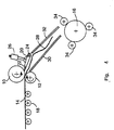
- Figures 1, 2, 3, 4 and 5 are different views of the winding system pictured, the same elements in its structure with the same digits be designated.
- Number 10 indicates an upper pinch roller, which with a lower pinch roller 12 cooperates to form a thin steel band 14 move on (e.g. to a mandrel 16).
- the tape runs on one Drain roller table or a cooling roller table 18.
- the front end 28 of the belt 14 is pressed down by the flap guide 20, which rests on the roller 10, so that the band 14 is prevented from being drawn due to the high Speed up around the pinch roller 10.
- the section 22 of the Flap guide 20, which rests on the pinch roller 10, preferably consists of a low-friction, durable material to prevent wear and scoring prevent the surface of the roller 10, and is on the flap guide 20th by suitable conventional fasteners according to the prior art attached. Suitable materials for this part 22 are for this purpose "Micarta" -like phenolic or melamine resin textile composites.
- the Flap guide 20 is by suitable actuating means 26 around the Swivel axis 24 movable, wherein it is in the actuating means 26 z. B. around a hydraulic or pneumatic cylinder or a cam cam roller mechanism etc. can act.
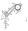
- the flap guide 20 by actuating means 26 in a second position moves, as shown in Fig. 2, in which the section 22 of the mentioned guide no longer abuts the roller 10.
- This second position is the normal operating position of the guide during the actual winding (on the one hand to excessive wear of the roller and the guide avoid and on the other hand reduce the force required to drive the upper Pinch roller is required while the tape is being wound).
- the mandrel 16 is provided with winding rollers 34, which form a regular contribute helical collar 36 around mandrel 16.
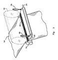
- a winding system is shown, the two arranged one behind the other Includes winding devices.
- the flap guide 20 is adapted so that it is a can assume the third position, in which it is close to the lower pinch roller 12th (after the formation of the collar on the mandrel 16 is completed and by cutting the tape 14 creates a new front end 28 so that the mandrel 48 can be loaded alternately next).
- the low-friction Tip 22 prevents the new front end 28 from around the pinch roller 12 wraps.
- the flap guide enables the belt 14 to further passage towards the pinch rollers 38 and 40 while the Pinch roller 10 was raised to free passage of the belt 14 too enable.
- the tip 22 is off the surface the roller 12 raised and moved back to the released second position.
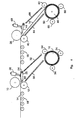
- the Flap guide 44 functions in the same way as flap guide 20, to ensure that the new front end 28 between the guide plates 64 and 66 is deflected and led to the corresponding second mandrel 48 becomes. Thereafter, the flap guide 44 (by the action of the cylinder 68) in the second position moves (as shown in Fig. 4) while the belt 14 turns the mandrel 48 is wound up and in connection with the winding rollers 60 a bundle 50 is wound.
- Fig. 5 is a control for the automatic positioning of the Flap guide 20 shown.
- the sensor 52 arranged upstream transmits a signal 53 to a programmable controller 54 that is a leading end 28 of the belt 14 in the direction of the pinch rollers 10 and 12 moves.
- the Actuator 56 which is controlled by the controller 54, responds to the called signal 53 and causes the hydraulic cylinder 26, the guide 20 in their move first position in which it rests on the roller 10.
- the sensor 58 sends a signal 62 to the Controller 54 which then controls actuator 56 to close cylinder 26 causing the flap guide 20 to move to the second position (thereby an unnecessarily long contact of the edge portion 22 of the flap guide 20 with the Pinch roller 10 is avoided).
Abstract
Description
Die vorliegende Erfindung betrifft ein Verfahren und eine Vorrichtung für die Führung von dünnem Stahlband, das in einem kontinuierlichen Walzwerk aufgewickelt wird, um zu verhindern, daß sich das genannte Stahlband um andere Rollen als den beabsichtigten Wickeldorn wickelt. Die Erfindung ist besonders geeignet für Anwendungen, bei denen warmgewalztes Stahlband aus stranggegossenen Brammen oder Stäben produziert wird.The present invention relates to a method and an apparatus for the Guiding thin steel strip in a continuous rolling mill is wound up in order to prevent the said steel strip from being wrapped around others Rolls as the intended winding mandrel. The invention is special suitable for applications where hot rolled steel strip is made of continuously cast slabs or bars is produced.
Die typische Anwendung des Erfindungsgegenstandes wird beispielsweise notwendig, wenn bei Metallbandwalzwerken die Stärke des Bandes unter 2 mm beträgt und insbesondere bei Stahl, wenn die Stärke unter 1,5 mm beträgt.The typical application of the subject of the invention is, for example necessary if the thickness of the strip is less than 2 mm for metal strip rolling mills is and especially for steel if the thickness is less than 1.5 mm.
Dünnes warmgewalztes Stahlband wird im allgemeinen hergestellt, indem die Dicke von gegossenen Brammen in aufeinanderfolgenden Walzschritten verringert wird, bis die gewünschte Bandstärke erreicht ist. Am Ende des Walzwerks befindet sich normalerweise eine Wickelmaschine, auf der das Band zum Transport zu einem Bund aufgewickelt wird. Thin hot rolled steel strip is generally made by the Cast slab thickness reduced in successive rolling steps until the desired tape thickness is reached. At the end of the rolling mill there is usually a winding machine on which the tape for Transport is wound up into a bundle.
Die Wickelmaschine umfaßt mehrere Stützwalzen und mindestens ein Paar Klemmrollen, die das Band in der gewünschten Geschwindigkeit und mit der gewünschten Spannung antreiben, bevor es in Eingriff mit einem Wickeldorn gebracht und auf diesen aufgewickelt wird.The winding machine comprises several support rollers and at least one pair Pinch rollers that pull the tape at the desired speed and with the desired tension before engaging a mandrel brought and wound on this.
Die Klemmrollen sind üblicherweise in einer höheren Position im Verhältnis zur Rolle der Wickelmaschine angeordnet, und eine Reihe von Führungsblechen zwingt das Band zum Wickeldorn. Wickelmaschinen nach dem Stand der Technik umfassen eine schwenkbar bewegliche Klappenführung, die ihre Position so ändern kann, daß sie in Werken, die zur Steigerung der Produktivität des Walzwerks mit mehreren Wickeldornen ausgestattet sind, das vordere Bandende in Richtung auf einen von einer Mehrzahl von Wickeldornen umlenkt.The pinch rollers are usually in a higher position relative to Roll of the winding machine arranged, and a number of guide plates forces the tape to the winding mandrel. State-of-the-art winding machines include a pivoting flap guide that positions it so can change that in works that increase the productivity of the Rolling mill are equipped with several mandrels, the front end of the strip deflected towards one of a plurality of mandrels.
Bei Klappenführungen nach dem Stand der Technik bleibt ein Spalt von mindestens 1 bis 2 mm zwischen dem Führungsende und der oberen Klemmrolle, der je nach der erwarteten Bandstärke gewählt wird. Ein kleinerer Spalt wurde bislang aufgrund der normalen Spiel- und Toleranzvariablen nicht als sinnvoll erachtet. Wenn die Stärke des Bandes mehr als etwa 2,0 mm bis 1,5 mm beträgt, treten beim Transport des Bands normalerweise keine Probleme auf, aber wenn die Stärke weniger als etwa 1,5 mm beträgt, kann das Band durch den genannten Spalt laufen und sich um die Klemmrolle wickeln, was zu Verzögerungen führt und Ausschuß verursacht. Je dünner das Band, desto flexibler ist es, und desto höher ist die sich ergebende Geschwindigkeit (üblicherweise mehr als 10m/Sek. bei einer Bandstärke von 1, 5 mm oder weniger). Die hohe Bandgeschwindigkeit führt manchmal dazu, daß sich das vordere Bandende im Durchgang durch die Kühlungseinrichtungen des Werks nach oben hebt, und wenn die Biegung des vorderen Bandendes in etwa der Biegung der Klemmrolle entspricht, ist es sehr wahrscheinlich, daß sich das Band um die genannte Klemmrolle wickelt. Die Erfindung ist somit besonders sinnvoll bei Wickelsystemen in der Herstellung von dünnem Stahlband. In the case of flap guides according to the prior art, a gap of at least 1 to 2 mm between the leading end and the upper pinch roller, which is chosen according to the expected band strength. A smaller gap was created So far not useful because of the normal game and tolerance variables considered. If the thickness of the tape is more than about 2.0 mm to 1.5 mm, Normally there are no problems when transporting the belt, but if the thickness is less than about 1.5 mm, the tape can be replaced by the above Run gap and wrap around the pinch roller, which leads to delays and Committee caused. The thinner the tape, the more flexible it is and the higher is the resulting speed (usually more than 10m / sec at a band thickness of 1.5 mm or less). The high belt speed leads sometimes to the fact that the front end of the tape in the passage through the Cooling equipment of the factory lifts up, and when the bend of the front end of the tape roughly corresponds to the bend of the pinch roller, it is very likely that the tape will wrap around the pinch roller. The The invention is therefore particularly useful in winding systems in the production of thin steel band.
Zwar wurden mehrere Vorschläge geprüft und erprobt, wie das vordere Bandende innerhalb des normalen Weges gehalten werden kann, aber die Lösung dieses Problems wurde schließlich von den Anmeldern entdeckt, als die herkömmliche Klappenführung umgebaut und so betrieben wurde, daß sie kurzzeitig und nicht abrasiv tatsächlich eng an der oberen Klemmrolle anliegt, wenn das vordere Bandende durch die Rolle läuft, wodurch im Effekt der Spalt geschlossen wird (der nach dem Stand der Technik eine notwendige Anforderung war). Um unerwünschten relativ schnellen Verschleiß und Riefenbildung auf der Klemmrollenoberfläche zu vermeiden, die wiederum die Qualität des Bandes beeinträchtigen würden, besteht die Spitze der Klappenführung, die an der Klemmrolle anliegt, aus einem Material mit einem sehr niedrigen Reibungskoeffizienten. Eins der bevorzugten Materialien für diese Anwendung ist ein faserverstärkter Verbundwerkstoff, der als "Micarta" bekannt ist (Warenzeichen der Westinghouse Electric Corporation), der als hartes, nicht abrasives und spanend zu bearbeitendes Material viele Anwendungen findet; aber auch andere Materialien können hierfür verwendet werden, solange sie nicht zu erheblichem Verschleiß oder zu Riefen auf den Klemmrollen führen.Several suggestions were examined and tried out, such as the front end of the belt can be kept within the normal path, but the solution to this Problems was eventually discovered by the applicants as the conventional one Flap guide was rebuilt and operated so that it was brief and not abrasive actually fits snugly against the upper pinch roller when the front one The end of the tape runs through the roll, which effectively closes the gap (the was a necessary requirement according to the state of the art). Around unwanted relatively quick wear and scoring on the Avoid pinch roller surface, which in turn affects the quality of the tape would affect, the tip of the flap guide, which is on the Pinch roller is made of a material with a very low Coefficient of friction. One of the preferred materials for this application is a fiber reinforced composite material known as "Micarta" (trademark Westinghouse Electric Corporation), which is considered hard, non - abrasive and material to be machined finds many uses; but also others Materials can be used for this as long as they are not too substantial Wear or scoring on the pinch rollers.
Bei einer Recherche im Zusammenhang mit der vorliegenden Erfindung wurden folgende Patente gefunden: U.S. 2,920,838 an Priestley; U.S. 4,047,416 an Johnson; U.S. 4,761,983 an Ginzburg et al. und U.S. 5,479,807 an Moser, deren technische Tatbestände durch diesen Hinweis in diese Anmeldung aufgenommen werden.During a search in connection with the present invention found the following patents: U.S. 2,920,838 to Priestley; U.S. 4,047,416 Johnson; U.S. 4,761,983 to Ginzburg et al. and U.S. 5,479,807 to Moser, whose technical facts are included in this application by this note become.
Im Patent an Priestley wird eine Bandwickelvorrichtung für das Aufwickeln von kontinuierlichem Band mit relativ hoher Stärke offenbart, deren Aufgabe es ist, unerwünschte Riefen auf dem Band zu verhindern, die durch den Druckaufbau verursacht werden, wenn die Rollen der Wickelmaschine an der Überlappung oder am Punkt des gestiegenen Bunddurchmessers auf das Band treffen, und die ebenfalls darauf abzielt, gebogene Führungen und Flüssigkeitsstrahlen vorzusehen, die auf das vordere Bandende auftreffen, um zu erreichen, daß sich das Band beim Einlaufen in die Wickelmaschine in Richtung auf die Umfangsfläche einer sich drehenden Spule biegt und dagegen gedrückt wird. Dieses Patent sieht nicht die Lösung vor, die von der vorliegenden Erfindung vorgesehen ist, um die bei dünnem Band auftretenden Wickelprobleme zu lösen und weist auch nicht auf eine solche Lösung hin.The Priestley patent discloses a tape winder for winding continuous tape of relatively high strength, whose job is to to prevent unwanted scoring on the tape caused by pressure build-up caused when the rollers of the winding machine overlap or hit the tape at the point of increased coil diameter, and the also aims at curved guides and liquid jets to be provided, which impinge on the front end of the tape to achieve that the tape as it enters the winder towards the Circumferential surface of a rotating coil bends and is pressed against it. This patent does not provide the solution to the present invention is provided to solve the winding problems occurring with thin tape and also does not indicate such a solution.
Im Patent an Johnson wird eine Vorrichtung für das Abwickeln und Richten von Bandmaterial erheblicher Stärke und für die Führung des vorderen Endes des abgewickelten Materials in einen Richt- und Speisemechanismus offenbart. Dieses Patent offenbart jedoch nicht das Problem des Aufwickelns von dünnem Rand, das durch die vorliegende Erfindung gelöst wird.The Johnson patent discloses a device for unwinding and straightening Tape material of considerable strength and for guiding the front end of the developed material in a directional and feed mechanism disclosed. However, this patent does not disclose the problem of winding thin Edge solved by the present invention.
Im Patent an Ginzburg et al. werden ein Verfahren und eine Vorrichtung für das
Aufwickeln von Material auf eine Wickeltrommel entlang einer Bandlaufebene in
einem Umkehrwarmwalzwerk beschrieben. Die Vorrichtung umfaßt eine Schürze
34, die von einem Hydraulikzylinder schwenkbar bewegt wird, wird aber nicht
verwendet, um zu verhindern, daß sich Bandmaterial um Klemmrollen wickelt.In the patent to Ginzburg et al. are a method and an apparatus for the
Winding material onto a winding drum along a belt running plane in
a reverse hot rolling mill described. The device includes an
Im Patent an Moser wird ein Wickelofen für ein warmgewalztes Band offengelegt, umfassend eine bandaufnehmende Führung mit einem Ende, das in bandaufnehmender Position neben der Wickeltrommel angeordnet ist. Diese Führung ist jedoch nicht dazu gedacht, zu verhindern, daß sich das Band um Klemmrollen wickelt oder die genannten Rollen berührt.The Moser patent discloses a winding furnace for a hot-rolled strip, comprising a tape-receiving guide with one end that is in tape-receiving position is arranged next to the winding drum. This However, leadership is not meant to prevent the tape from wrapping around Pinch rolls wraps or touches the roles mentioned.
In keinem der vorgenannten Patente werden die Probleme angesprochen oder angedeutet, die von der vorliegenden Erfindung gelöst werden, und ihre Lehren enthalten nicht die Konstruktion und den Betrieb einer Führung wie in der vorliegenden Erfindung beansprucht. None of the aforementioned patents address the problems or indicated, which are solved by the present invention, and their teachings do not include the construction and operation of a guide as in the claimed present invention.
Eine Aufgabe der vorliegenden Erfindung ist daher ein verbessertes Wickelsystem für den Einsatz in der Produktion von dünnem Stahlband, zum Beispiel bei Wickelsystemen in Verbindung mit Bandwarmwalzwerken in Stranggußanlagen.An object of the present invention is therefore an improved winding system for use in the production of thin steel strips, for example at Winding systems in connection with hot strip mills in continuous casting plants.
Eine weitere Aufgabe der Erfindung ist eine verbesserte Vorrichtung für die Führung eines dünnen Stahlbands zum Dorn einer Wickelmaschine ohne Störung des normalen Betriebs und Beeinträchtigung der hohen Bewegungsgeschwindigkeit der Klemmrollen in der genannten Wickelmaschine.Another object of the invention is an improved device for the Guiding a thin steel band to the mandrel of a winding machine without interference normal operation and impairment of high Speed of movement of the pinch rollers in the mentioned winding machine.
Weitere Aufgaben der Erfindung werden teilweise offensichtlich oder nachfolgend deutlich gemacht.Other objects of the invention will become apparent in part or hereinafter made clear.
Dementsprechend verfügt ein erfindungsgemäßes Wickelsystem über mehrere Merkmale) die dem genannten Wickelsystem einen zuverlässigen Betrieb ermöglichen und die Betriebskosten von Stahlwerken durch die Verringerung von Stillstandszeiten und Ausbringungsverlusten senken.Accordingly, a winding system according to the invention has several Features) that the mentioned winding system reliable operation enable and reduce the operating costs of steelworks Reduce downtimes and output losses.
Die Aufgaben der vorliegenden Erfindung werden generell erreicht durch das Wickelsystem der Anmelder für den Transport eines dünnen Bandes (wie bereits allgemein beschrieben) und insbesondere umfassend: (a) mindestens ein Paar von Klemmrollen und mindestens einen Wickeldorn; (b) eine Führung, die entlang des Wegs angeordnet ist, den das genannte dünne Band von den genannten Klemmrollen zu dem genannten Wickeldorn beschreibt, wobei diese Führung mindestens in zwei Positionen bewegt werden kann: eine erste Position, in der ein Ende der genannten Führung an einer der genannten Klemmrollen anliegt, so daß sich das dünne Band nicht nach oben um die genannte Klemmrolle wickeln kann und ebenfalls gezwungen wird, einen festgelegten Weg in Richtung auf den genannten Wickeldorn zu beschreiben, und eine zweite Position, in der die genannte Führung nicht an der genannten Klemmrolle anliegt, wodurch während des Wickelvorgangs, nachdem das Band mit dem Wickeldorn in Eingriff gebracht wurde und um den genannten Wickeldorn gewickelt wird, unnötiger Verschleiß der Klemmrolle oder Riefenbildung auf der Oberfläche der Klemmrolle verhindert wird.The objects of the present invention are generally achieved by the Applicant's winding system for the transport of a thin belt (as before generally described) and in particular comprising: (a) at least one pair of pinch rollers and at least one winding mandrel; (b) a guide that goes along is arranged along the path that said thin band of said Clamping rollers to the winding mandrel described, this guide can be moved in at least two positions: a first position in which one End of said guide abuts one of the pinch rollers mentioned, so that the thin tape cannot wrap up around the pinch roller and is also forced to follow a predetermined path towards the to describe the winding mandrel, and a second position in which the said guide does not abut the said pinch roller, whereby during of the winding process after the tape is engaged with the winding mandrel was and is wound around the winding mandrel, unnecessary wear of the Pinch roller or scoring on the surface of the pinch roller is prevented.
In einer weiteren Ausführungsform umfaßt das erfindungsgemäße Wickelsystem eine Mehrzahl von Wickeldornen, wobei die Führung in eine dritte Position bewegt werden kann, in der die genannte Führung dem Band ermöglicht, einen anderen Weg zu einem anderen Wickeldorn zu beschreiben, während ein fertiger Bund auf einem anderen Dorn entnommen wird, wodurch die Produktivität des gesamten Wickelsystems gesteigert wird.In a further embodiment, the winding system according to the invention comprises a plurality of mandrels, with the guide moving to a third position in which the said guide enables the tape to be another Way to describe another mandrel while a finished bundle is on Another mandrel is removed, reducing the productivity of the whole Winding system is increased.
Die Führung umfaßt eine Spitze aus einem nicht abrasiven, reibungsarmen Werkstoff wie etwa Micarta, so daß sie die Oberfläche der Klemmrolle nicht beschädigt. Die Führung wird als Reaktion auf ein Signal eines ersten, im vorgeschalteten Walzwerk angeordneten Sensors, daß eine neue Bramme gewalzt wird und daß sich das vordere Bandende den Klemmrollen nähert, automatisch in ihre ersten Position gebracht, in der sie an der Klemmrolle anliegt, und als Reaktion auf ein Signal eines zweiten, im nachgeschalteten Wickeldorn angeordneten Sensors, daß das Band um den genannten Dorn gewickelt wird, automatisch in ihre zweite Position in einem Abstand von der Klemmrolle gebracht.The guide includes a tip made of a non-abrasive, low-friction Material such as micarta so that it does not cover the surface of the pinch roller damaged. The leadership is responding to a signal from a first, im upstream rolling mill arranged sensor that a new slab is rolled and that the front end of the strip approaches the pinch rollers, automatically brought into its first position in which it lies against the pinch roller, and in response to a signal from a second winding mandrel located downstream arranged sensor that the tape is wrapped around said mandrel, automatically into its second position at a distance from the pinch roller brought.
In dieser Beschreibung und den beigefügten Zeichnungen werden einige
bevorzugte Ausführungsformen der Erfindung gezeigt und beschrieben und
verschiedene Alternativen und Modifikationen vorgeschlagen; es wird jedoch
darauf hingewiesen, daß diese keinesfalls als erschöpfend anzusehen sind und
daß zahlreiche Änderungen und Modifikationen innerhalb des Schutzbereichs der
Erfindung möglich sind. Die hierin enthaltenen Vorschläge wurden zur
Verdeutlichung ausgewählt und aufgenommen, damit andere Fachkundige die
Erfindung und ihre Grundsätze besser verstehen können und somit in der Lage
sind, sie in einer Vielzahl von Formen zu modifizieren, wie es jeweils für die
Bedingungen des besonderen Anwendungszwecks am besten geeignet ist.
Zwar wird die Erfindung im Einsatz in der Produktion und dem Aufwickeln von warmgewalzten Stahlband als einem der unmittelbaren Anwendungszwecke der Erfindung beschrieben, aber für den Fachkundigen ist offensichtlich, daß sie in ihren weitergehenden Aspekten in anderen ähnlichen Anwendungen bei industriellen Verfahren, beispielsweise in der Produktion von Aluminiumband, vorteilhaft genutzt werden kann.Although the invention is used in the production and winding of hot rolled steel strip as one of the immediate uses of Invention described, but it is obvious to those skilled in the art that they are in their broader aspects in other similar applications industrial processes, for example in the production of aluminum strip, can be used advantageously.
In Abbildungen 1, 2, 3, 4 und 5 sind verschiedene Ansichten des Wickelsystems
abgebildet, wobei die gleichen Elemente in seinem Aufbau mit denselben Ziffern
bezeichnet werden. Ziffer 10 kennzeichnet eine obere Klemmrolle, die mit einer
unteren Klemmrolle 12 zusammenwirkt, um ein dünnes Stahlband 14
weiterzuziehen (z. B. zu einem Wickeldorn 16). Das Band läuft auf einem
Ablaufrollgang oder einem Kühlrollgang 18. Das vordere Ende 28 des Bandes 14
wird von der Klappenführung 20 nach unten gedrückt, die an der Rolle 10 anliegt,
so daß verhindert wird, daß sich das Band 14 aufgrund der hohen
Geschwindigkeit nach oben um die Klemmrolle 10 wickelt. Das Teilstück 22 der
Klappenführung 20, das an der Klemmrolle 10 anliegt, besteht vorzugsweise aus
einem reibungsarmen, haltbaren Werkstoff, um Verschleiß und Riefenbildung auf
der Oberfläche der Rolle 10 zu verhindern, und ist an der Klappenführung 20
durch geeignete herkömmliche Befestigungsmittel nach Stand der Technik
befestigt. Zu diesem Zweck geeignete Werkstoffe für dieses Teilstück 22 sind
"Micarta"-ähnliche Phenol- oder Melaminharz-Textilverbundstoffe. Die
Klappenführung 20 ist durch geeignete Betätigungsmittel 26 um die
Schwenkachse 24 beweglich, wobei es sich bei den Betätigungsmitteln 26 z. B.
um einen Hydraulik- oder Pneumatikzylinder oder einen Nocken-Kurvenrollenmechanismus
usw. handeln kann. Da die Spitze 22 der
Klappenführung 20 an der Oberfläche der Rolle 10 anliegt, ohne daß ein Spalt
zwischen beiden verbleibt, wird das vordere Ende 28 des Bandes 14 gezwungen,
einen Weg zu beschreiben, der das Band 14 zum Dorn 16 führt. Der Weg des
Bandes zum Wickeldorn 16 wird durch geeignete Führungsbleche 30 und 32
festgelegt.Figures 1, 2, 3, 4 and 5 are different views of the winding system
pictured, the same elements in its structure with the same digits
be designated.
Nachdem das vordere Ende 28 des Bandes 14 mit dem Dorn 16 in Eingriff
gebracht und von diesem aufgenommen wurde und um diesen herum
aufgewickelt wird, wird die Klappenführung 20 durch Betätigungsmittel 26 in eine
zweite Position bewegt, wie in Abb. 2 dargestellt, in der das Teilstück 22 der
genannten Führung nicht mehr an der Rolle 10 anliegt. Diese zweite Position ist
die normale Betriebsposition der Führung während des eigentlichen Aufwickelns
(um einerseits einen überhöhten Verschleiß der Rolle und der Führung zu
vermeiden und andererseits die Kraft zu verringern, die für den Antrieb der oberen
Klemmrolle erforderlich ist, während das Band aufgewickelt wird). Der Wickeldorn
16 ist mit Wickelrollen 34 versehen, die zur Bildung eines regelmäßigen
spiralförmigen Bundes 36 um den Dorn 16 herum beitragen.After the
In Abb. 4 ist ein Wickelsystem dargestellt, das zwei hintereinander angeordnete
Wickeleinrichtungen umfaßt. Die Klappenführung 20 ist so angepaßt, daß sie eine
dritte Position einnehmen kann, in der sie eng an der unteren Klemmrolle 12
anliegt (nachdem die Bundbildung auf dem Dorn 16 abgeschlossen ist und durch
das Durchschneiden des Bands 14 ein neues vorderes Ende 28 entsteht, damit
der Dorn 48 als nächstes im Wechsel beschickt werden kann). Die reibungsarme
Spitze 22 verhindert, daß sich das neue vordere Ende 28 um die Klemmrolle 12
wickelt. In dieser Position ermöglicht die Klappenführung dem Band 14 den
weiteren Durchgang in Richtung auf die Klemmrollen 38 und 40, während die
Klemmrolle 10 angehoben wurde, um einen freien Durchgang des Bandes 14 zu
ermöglichen. Nachdem das neue vordere Ende 28 über die Klappenführung 20
(wie in Abbildung 4 dargestellt) gelaufen ist, wird die Spitze 22 von der Oberfläche
der Rolle 12 angehoben und wieder in die gelöste zweite Position bewegt. Die
Klappenführung 44 funktioniert auf die gleiche Weise wie die Klappenführung 20,
um sicherzustellen, daß das neue vordere Ende 28 zwischen die Führungsbleche
64 und 66 abgelenkt wird und weiter zum entsprechenden zweiten Dorn 48 geführt
wird. Danach wird die Klappenführung 44 (durch die Wirkung des Zylinders 68) in
die zweite Position bewegt (wie in Abb. 4 dargestellt), während das Band 14 um
den Dorn 48 aufgewickelt wird und in Verbindung mit den Wickelrollen 60 zu
einem Bund 50 gewickelt wird.In Fig. 4 a winding system is shown, the two arranged one behind the other
Includes winding devices. The
In Abb. 5 ist schematisch eine Steuerung für die automatische Positionierung der
Klappenführung 20 dargestellt. Der vorgeschaltet angeordnete Sensor 52 sendet
ein Signal 53 an eine programmierbare Steuerung 54, daß sich ein vorderes Ende
28 des Bandes 14 in Richtung auf die Klemmrollen 10 und 12 bewegt. Das
Stellglied 56, das von der Steuerung 54 angesteuert wird, reagiert auf das
genannte Signal 53 und veranlaßt den Hydraulikzylinder 26, die Führung 20 in ihre
erste Position zu bewegen, in der sie an der Rolle 10 anliegt. Sobald das Band 14
um den Dorn 16 gewickelt wird, sendet der Sensor 58 ein Signal 62 an die
Steuerung 54, die dann das Stellglied 56 ansteuert, um den Zylinder 26 zu
veranlassen, die Klappenführung 20 in die zweite Position zu bewegen (wodurch
ein unnötig langer Kontakt des Kantenteilstücks 22 der Klappenführung 20 mit der
Klemmrolle 10 vermieden wird).In Fig. 5 is a control for the automatic positioning of the
Es sollte klar sein, daß die hier beschriebenen Ausführungsformen der Erfindung nur zur Verdeutlichung dienen, und für den Fachkundigen ist offensichtlich, daß zahlreiche Änderungen an diesen Ausführungsformen vorgenommen werden, ohne den Schutzbereich der beanspruchten Erfindung zu verlassen.It should be understood that the embodiments of the invention described herein are for illustration purposes only, and it is obvious to those skilled in the art that numerous changes are made to these embodiments, without leaving the scope of the claimed invention.
Claims (20)
dadurch gekennzeichnet,
daß das genannte Band eine Stärke von weniger als etwa 2 mm hat. Thin tape winding system according to claim 1,
characterized,
that said tape has a thickness of less than about 2 mm.
dadurch gekennzeichnet,
daß das genannte Band eine Stärke von weniger als etwa 1,5 mm hat.Thin tape winding system according to claim 1,
characterized,
that said tape has a thickness of less than about 1.5 mm.
dadurch gekennzeichnet,
daß es sich bei dem genannten Band um Stahlband handelt.Thin tape winding system according to claim 3,
characterized,
that it is a steel band in the said band.
dadurch gekennzeichnet,
daß das genannte Band mit einer Geschwindigkeit von mehr als 10 m/Sek. zu einem Bund aufgewickelt wird.Thin tape winding system according to claim 4,
characterized,
that said belt at a speed of more than 10 m / sec. is wound into a bundle.
dadurch gekennzeichnet,
daß das Teilstück der genannten Führung, das an der genannten Klemmrolle anliegt, aus einem reibungsarmen, haltbaren Werkstoff besteht.Thin tape winding system according to claim 4,
characterized,
that the section of said guide, which rests on said clamping roller, consists of a low-friction, durable material.
dadurch gekennzeichnet,
daß der genannte reibungsarme Werkstoff ein Kunststofflaminat ist, das Papier oder Gewebe aus Zellulose-, Glas-, Asbest- oder Synthetikfasern umfaßt, die mit Phenol- oder Melaminharzen gebunden werden.Thin tape winding system according to claim 6,
characterized,
that said low friction material is a plastic laminate comprising paper or tissue made of cellulose, glass, asbestos or synthetic fibers which are bound with phenolic or melamine resins.
dadurch gekennzeichnet,
daß die genannte Klappenführung so angepaßt ist, daß sie durch Betätigungsmittel als Reaktion auf ein Signal, daß sich das vordere Ende eines neuen Bandes den genannten Klemmrollen nähert, in die genannte erste Position bewegt werden kann. Thin tape winding system according to claim 6,
characterized,
that said flap guide is adapted to be moved to said first position by actuating means in response to a signal that the front end of a new belt is approaching said pinch rollers.
dadurch gekennzeichnet,
daß die genannte Klappenführung so angepaßt ist, daß sie durch Betätigungsmittel als Reaktion auf ein Signal, daß das genannte Band im Eingriff mit dem Wickeldorn ist und um den genannten Wickeldorn aufgewickelt wird, in die genannte zweite Position bewegt werden kann.Thin tape winding system according to claim 6,
characterized,
that said flap guide is adapted to be moved to said second position by actuating means in response to a signal that said tape is in engagement with and wound around said mandrel.
dadurch gekennzeichnet,
daß die genannte Klappenführung so angepaßt ist, daß sie durch Betätigungsmittel als Reaktion auf ein Signal, daß das Band im Eingriff mit dem genannten Wickeldorn ist und um den genannten Wickeldorn aufgewickelt wird, in die genannte zweite Position bewegt werden kann.Thin tape winding system according to claim 8,
characterized,
that said flap guide is adapted to be moved to said second position by actuating means in response to a signal that the tape is in engagement with said winding mandrel and is being wound around said winding mandrel.
dadurch gekennzeichnet,
daß die genannte Klappenführung um eine Schwenkachse herum beweglich ist und das Betätigungsmittel einen Hydraulikzylinder umfaßt.Thin tape winding system according to claim 10,
characterized,
that said flap guide is movable about a pivot axis and the actuating means comprises a hydraulic cylinder.
dadurch gekennzeichnet,
daß die genannte Klappenführung um eine Schwenkachse herum beweglich ist und das Betätigungsmittel eine Nocken-Kurvenrollenvorrichtung umfaßt.Thin tape winding system according to claim 10,
characterized,
that said flap guide is movable about a pivot axis and the actuating means comprises a cam cam roller device.
dadurch gekennzeichnet,
daß das genannte Wickelsystem mehrere Sätze von Klemmrollen, Klappenführungen und Wickeldornen umfaßt und
dadurch gekennzeichnet,
daß die genannten Klappenführungen in eine dritte Position bewegt werden können, in der das genannte Band entlang der genannten Führung verlaufen kann, um auf einem anderen Wickeldorn des Wickelsystems aufgewickelt zu werden.Thin tape winding system according to claim 1,
characterized,
that said winding system comprises several sets of pinch rollers, flap guides and mandrels and
characterized,
that said flap guides can be moved to a third position in which said tape can run along said guide to be wound on another mandrel of the winding system.
dadurch gekennzeichnet,
daß das genannte Wickelsystem mehrere Sätze von Klemmrollen, Klappenführungen und Wickeldornen umfaßt und
dadurch gekennzeichnet,
daß die genannten Klappenführungen in eine dritte Position bewegt werden können, in der das genannte Band entlang der genannten Führung verlaufen kann, um auf einem anderen Wickeldorn des Wickelsystems aufgewickelt zu werden.Thin tape winding system according to claim 4,
characterized,
that said winding system comprises several sets of pinch rollers, flap guides and mandrels and
characterized,
that said flap guides can be moved to a third position in which said tape can run along said guide to be wound on another mandrel of the winding system.
dadurch gekennzeichnet,
daß das genannte Wickelsystem mehrere Sätze von Klemmrollen, Klappenführungen und Wickeldornen umfaßt und
dadurch gekennzeichnet,
daß die genannten Klappenführungen in eine dritte Position bewegt werden können, in der das genannte Band entlang der genannten Führung verlaufen kann, um auf einem anderen Wickeldorn des Wickelsystems aufgewickelt zu werden.Thin tape winding system according to claim 7,
characterized,
that said winding system comprises several sets of pinch rollers, flap guides and mandrels and
characterized,
that said flap guides can be moved to a third position in which said tape can run along said guide to be wound on another mandrel of the winding system.
dadurch gekennzeichnet,
daß das genannte Wickelsystem mehrere Sätze von Klemmrollen, Klappenführungen und Wickeldornen umfaßt und
dadurch gekennzeichnet,
daß die genannten Klappenführungen in eine dritte Position bewegt werden können, in der das genannte Band entlang der genannten Führung verlaufen kann, um auf einem anderen Wickeldorn des Wickelsystems aufgewickelt zu werden.Thin tape winding system according to claim 10,
characterized,
that said winding system comprises several sets of pinch rollers, flap guides and mandrels and
characterized,
that said flap guides can be moved to a third position in which said tape can run along said guide to be wound on another mandrel of the winding system.
dadurch gekennzeichnet,
daß die genannte Klappenführung durch Betätigungsmittel als Reaktion auf ein Signal, daß das genannte Band im Eingriff mit dem genannten Wickeldorn ist und um den genannten Wickeldorn aufgewickelt wird, in die genannte zweite Position bewegt wird.Method for winding thin steel strip according to claim 18,
characterized,
that said flap guide is moved to said second position by actuating means in response to a signal that said tape is in engagement with said winding mandrel and is wound around said winding mandrel.
dadurch gekennzeichnet,
daß die genannte Klappenführung als Reaktion auf ein Signal, daß das genannte Band im Eingriff mit dem genannten Wickeldorn ist und um den genannten Wickeldorn aufgewickelt wird, durch Betätigungsmittel in die genannte zweite Position bewegt wird.Method for winding thin steel strip according to claim 18,
characterized,
that said flap guide is moved to said second position by actuating means in response to a signal that said tape is in engagement with said winding mandrel and is wound around said winding mandrel.
Applications Claiming Priority (2)
| Application Number | Priority Date | Filing Date | Title |
|---|---|---|---|
| US82123 | 1998-05-19 | ||
| US09/082,123 US6039283A (en) | 1998-05-19 | 1998-05-19 | Thin strip coiling system |
Publications (3)
| Publication Number | Publication Date |
|---|---|
| EP0958867A2 true EP0958867A2 (en) | 1999-11-24 |
| EP0958867A3 EP0958867A3 (en) | 2001-05-02 |
| EP0958867B1 EP0958867B1 (en) | 2007-06-27 |
Family
ID=22169220
Family Applications (1)
| Application Number | Title | Priority Date | Filing Date |
|---|---|---|---|
| EP99109588A Expired - Lifetime EP0958867B1 (en) | 1998-05-19 | 1999-05-14 | Strip winding apparatus |
Country Status (5)
| Country | Link |
|---|---|
| US (1) | US6039283A (en) |
| EP (1) | EP0958867B1 (en) |
| AT (1) | ATE365593T1 (en) |
| DE (1) | DE59914389D1 (en) |
| ES (1) | ES2293703T3 (en) |
Cited By (5)
| Publication number | Priority date | Publication date | Assignee | Title |
|---|---|---|---|---|
| DE10162433A1 (en) * | 2001-12-18 | 2003-07-10 | Masch Und Werkzeugbau Gmbh | Driving metal strips from a metal casting installation comprises adjusting one drive roll on a prescribed region of a circulating strip about the longitudinal axis of the other drive roll |
| US8256256B2 (en) | 2006-10-02 | 2012-09-04 | Siemens Vai Metals Technologies Gmbh | Coiling furnace |
| US10413952B2 (en) | 2014-03-20 | 2019-09-17 | Primetals Technologies Japan, Ltd. | Coiler device and gate device provided with guide unit |
| CN111891803A (en) * | 2020-09-02 | 2020-11-06 | 温州正海密封件有限公司 | Automatic winding machine |
| CN114700390A (en) * | 2022-03-28 | 2022-07-05 | 北京首钢冷轧薄板有限公司 | Control method and device for strip plate and strip head of cold rolling processing line |
Families Citing this family (16)
| Publication number | Priority date | Publication date | Assignee | Title |
|---|---|---|---|---|
| DE19835110A1 (en) * | 1998-08-04 | 2000-02-10 | Schloemann Siemag Ag | Deflection method and deflection device for a band, in particular a metal band |
| AUPP964499A0 (en) * | 1999-04-08 | 1999-04-29 | Bhp Steel (Jla) Pty Limited | Casting strip |
| GB0020160D0 (en) * | 2000-08-17 | 2000-10-04 | Vai Ind Uk Ltd | Steckel furnace coiler and apparatus therefor |
| US6588245B2 (en) * | 2001-08-15 | 2003-07-08 | General Electric Co. | Roll gap control for coiler |
| US6607841B2 (en) * | 2001-10-16 | 2003-08-19 | Albert Chow | Silicon steel sheet |
| DE10208964A1 (en) * | 2002-02-28 | 2003-09-18 | Sms Demag Ag | Deflection device for a belt in a reel system |
| DE20209752U1 (en) * | 2002-06-20 | 2002-09-19 | Mst Maschb Gmbh | Device for winding a web of material |
| JP2010504216A (en) * | 2006-09-25 | 2010-02-12 | エス・エム・エス・ジーマーク・アクチエンゲゼルシャフト | Method and apparatus for winding a strip with a winding mandrel. |
| DE102007015636A1 (en) * | 2006-11-24 | 2008-05-29 | Sms Demag Ag | Device for guiding a metal strip and method for its operation |
| CN103191956B (en) * | 2012-01-05 | 2015-05-06 | 鞍钢股份有限公司 | Coiler guide and guard device |
| US9216924B2 (en) * | 2012-11-09 | 2015-12-22 | Corning Incorporated | Methods of processing a glass ribbon |
| US9566626B2 (en) * | 2013-12-04 | 2017-02-14 | Sms Group Gmbh | Apparatus for and method of winding-up a metal strip, and plant for producing a metal strip windable into a coil |
| JP5944428B2 (en) * | 2014-03-20 | 2016-07-05 | Primetals Technologies Japan株式会社 | Coiler device with chute guide |
| US9388017B1 (en) | 2015-02-06 | 2016-07-12 | Clifton E. Wolf | Accumulator reel for strip steel used to manufacture coiled tubing |
| CN108787752B (en) * | 2018-08-16 | 2024-02-27 | 马鞍山钢铁股份有限公司 | Guiding switching device capable of automatically adjusting gap |
| EP4019158B1 (en) * | 2020-12-23 | 2023-11-01 | Primetals Technologies Austria GmbH | Reel device for large thickness range of metal strips |
Citations (4)
| Publication number | Priority date | Publication date | Assignee | Title |
|---|---|---|---|---|
| US2920838A (en) | 1956-11-01 | 1960-01-12 | United Eng Foundry Co | Strip coiling apparatus |
| US4047416A (en) | 1976-10-14 | 1977-09-13 | F. J. Littell Machine Company | Uncoiling and straightening apparatus for strip material |
| US4761983A (en) | 1987-08-07 | 1988-08-09 | International Rolling Mill Consultants, Inc. | Method and apparatus for winding material on a drum |
| US5479807A (en) | 1993-03-05 | 1996-01-02 | Voest-Alpine Industrieanlagenbau Gmbh | Coiler furnace for a hot strip |
Family Cites Families (10)
| Publication number | Priority date | Publication date | Assignee | Title |
|---|---|---|---|---|
| US1326989A (en) * | 1917-11-21 | 1920-01-06 | Sundh August | Automatic blocking mechanism for strip-mills |
| US3608805A (en) * | 1968-05-31 | 1971-09-28 | Matsushita Electric Ind Co Ltd | Tape-forwarding means |
| US3688541A (en) * | 1969-10-20 | 1972-09-05 | Ishikawajima Harima Heavy Ind | Stripper guide |
| CA983063A (en) * | 1973-05-03 | 1976-02-03 | Reed International Limited | Web feeding apparatus |
| NL177287C (en) * | 1974-08-13 | 1985-09-02 | Hoesch Werke Ag | DRIVE DEVICE FOR TIRE ROLLED ROLLER. |
| US4384468A (en) * | 1981-09-29 | 1983-05-24 | Tippins Machinery Company, Inc. | Method and apparatus for coiling strip on a hot mill |
| AT393239B (en) * | 1989-06-08 | 1991-09-10 | Voest Alpine Ind Anlagen | REEL |
| DE4013582C1 (en) * | 1990-04-24 | 1991-07-11 | Mannesmann Ag, 4000 Duesseldorf, De | |
| JPH05123744A (en) * | 1991-10-29 | 1993-05-21 | Mitsubishi Heavy Ind Ltd | Device for coiling strip |
| DE19835110A1 (en) * | 1998-08-04 | 2000-02-10 | Schloemann Siemag Ag | Deflection method and deflection device for a band, in particular a metal band |
-
1998
- 1998-05-19 US US09/082,123 patent/US6039283A/en not_active Expired - Lifetime
-
1999
- 1999-05-14 EP EP99109588A patent/EP0958867B1/en not_active Expired - Lifetime
- 1999-05-14 AT AT99109588T patent/ATE365593T1/en active
- 1999-05-14 ES ES99109588T patent/ES2293703T3/en not_active Expired - Lifetime
- 1999-05-14 DE DE59914389T patent/DE59914389D1/en not_active Expired - Lifetime
Patent Citations (4)
| Publication number | Priority date | Publication date | Assignee | Title |
|---|---|---|---|---|
| US2920838A (en) | 1956-11-01 | 1960-01-12 | United Eng Foundry Co | Strip coiling apparatus |
| US4047416A (en) | 1976-10-14 | 1977-09-13 | F. J. Littell Machine Company | Uncoiling and straightening apparatus for strip material |
| US4761983A (en) | 1987-08-07 | 1988-08-09 | International Rolling Mill Consultants, Inc. | Method and apparatus for winding material on a drum |
| US5479807A (en) | 1993-03-05 | 1996-01-02 | Voest-Alpine Industrieanlagenbau Gmbh | Coiler furnace for a hot strip |
Cited By (7)
| Publication number | Priority date | Publication date | Assignee | Title |
|---|---|---|---|---|
| DE10162433A1 (en) * | 2001-12-18 | 2003-07-10 | Masch Und Werkzeugbau Gmbh | Driving metal strips from a metal casting installation comprises adjusting one drive roll on a prescribed region of a circulating strip about the longitudinal axis of the other drive roll |
| DE10162433B4 (en) * | 2001-12-18 | 2006-06-01 | Maschinen- Und Werkzeugbau Gmbh | Method and device for driving metal strips |
| US8256256B2 (en) | 2006-10-02 | 2012-09-04 | Siemens Vai Metals Technologies Gmbh | Coiling furnace |
| US10413952B2 (en) | 2014-03-20 | 2019-09-17 | Primetals Technologies Japan, Ltd. | Coiler device and gate device provided with guide unit |
| CN111891803A (en) * | 2020-09-02 | 2020-11-06 | 温州正海密封件有限公司 | Automatic winding machine |
| CN114700390A (en) * | 2022-03-28 | 2022-07-05 | 北京首钢冷轧薄板有限公司 | Control method and device for strip plate and strip head of cold rolling processing line |
| CN114700390B (en) * | 2022-03-28 | 2023-12-29 | 北京首钢冷轧薄板有限公司 | Control method and device for cold rolling treatment line band plate band head |
Also Published As
| Publication number | Publication date |
|---|---|
| EP0958867B1 (en) | 2007-06-27 |
| EP0958867A3 (en) | 2001-05-02 |
| DE59914389D1 (en) | 2007-08-09 |
| ATE365593T1 (en) | 2007-07-15 |
| ES2293703T3 (en) | 2008-03-16 |
| US6039283A (en) | 2000-03-21 |
Similar Documents
| Publication | Publication Date | Title |
|---|---|---|
| EP0958867B1 (en) | Strip winding apparatus | |
| DE2256024C2 (en) | Hot rolling mill for metallic rolling stock | |
| EP0498962B1 (en) | Method and means for realising a wound bobbin | |
| EP3229987B1 (en) | Apparatus for winding up a metal strip | |
| DE4013656C2 (en) | Device for splicing webs, in particular paper webs for the production of corrugated cardboard | |
| EP0255674B1 (en) | Apparatus for producing cast metal strip with an amorphous and/or fine crystal structure | |
| EP0619377B1 (en) | Coiler furnace | |
| DE19541095A1 (en) | Process for conveying a band of plastic material and conveyor table for the continuous conveyance of band-shaped plastic material | |
| DE19524729A1 (en) | Method and device for rolling strips with a non-uniform thickness and / or length distribution across their width | |
| AT394508B (en) | PLANT FOR PRODUCING STRAPPED WIRE ROLLS | |
| DE19680225C1 (en) | Coiler furnace for a hot strip | |
| DE2501319A1 (en) | Machine rolling off band material - has stationary mounted roller and bending roller mounted with coil on pivoting arms | |
| DE60118964T2 (en) | DEVICE AND METHOD FOR WRAPPING TRACKS | |
| EP0817688B1 (en) | Strip winder | |
| DE4425201C2 (en) | Method and device for separating a plastic material web in a roll cutting and winding machine | |
| DE2838563C2 (en) | Device for achieving tightly wound bundles of the same diameter when winding several narrow strips | |
| DE3828356C2 (en) | Device for influencing the position of hot rolled strip with a driving device | |
| DE2425454A1 (en) | Multi-roll winding machine - for continuous winding of bolts of cloth using constant tension | |
| DE2606301C2 (en) | Device for feeding and discharging metal strip | |
| AT407613B (en) | DEVICE FOR CONTINUOUSLY WINDING TAPE MATERIAL | |
| DE19812620A1 (en) | Reel for a thin metal band | |
| DE2607938A1 (en) | Metal strip uncoiler and straightener - has handles looped through thick stock on small floor area | |
| DE2431691C2 (en) | Machine for the continuous winding of a web of material | |
| DE1502769C (en) | Shear system for slitting metal strips | |
| DE10162433B4 (en) | Method and device for driving metal strips |
Legal Events
| Date | Code | Title | Description |
|---|---|---|---|
| PUAI | Public reference made under article 153(3) epc to a published international application that has entered the european phase |
Free format text: ORIGINAL CODE: 0009012 |
|
| 17P | Request for examination filed |
Effective date: 19990514 |
|
| AK | Designated contracting states |
Kind code of ref document: A2 Designated state(s): AT DE ES FR GB IT NL SE |
|
| AX | Request for extension of the european patent |
Free format text: AL;LT;LV;MK;RO;SI |
|
| RAP1 | Party data changed (applicant data changed or rights of an application transferred) |
Owner name: HYLSA, S.A. DE C.V. Owner name: SMS DEMAG AG |
|
| PUAL | Search report despatched |
Free format text: ORIGINAL CODE: 0009013 |
|
| AK | Designated contracting states |
Kind code of ref document: A3 Designated state(s): AT BE CH CY DE DK ES FI FR GB GR IE IT LI LU MC NL PT SE |
|
| AX | Request for extension of the european patent |
Free format text: AL;LT;LV;MK;RO;SI |
|
| AKX | Designation fees paid |
Free format text: AT DE ES FR GB IT NL SE |
|
| 17Q | First examination report despatched |
Effective date: 20030730 |
|
| GRAP | Despatch of communication of intention to grant a patent |
Free format text: ORIGINAL CODE: EPIDOSNIGR1 |
|
| GRAS | Grant fee paid |
Free format text: ORIGINAL CODE: EPIDOSNIGR3 |
|
| GRAA | (expected) grant |
Free format text: ORIGINAL CODE: 0009210 |
|
| AK | Designated contracting states |
Kind code of ref document: B1 Designated state(s): AT DE ES FR GB IT NL SE |
|
| REG | Reference to a national code |
Ref country code: GB Ref legal event code: FG4D Free format text: NOT ENGLISH |
|
| REG | Reference to a national code |
Ref country code: SE Ref legal event code: TRGR |
|
| REF | Corresponds to: |
Ref document number: 59914389 Country of ref document: DE Date of ref document: 20070809 Kind code of ref document: P |
|
| GBT | Gb: translation of ep patent filed (gb section 77(6)(a)/1977) |
Effective date: 20071004 |
|
| ET | Fr: translation filed | ||
| REG | Reference to a national code |
Ref country code: ES Ref legal event code: FG2A Ref document number: 2293703 Country of ref document: ES Kind code of ref document: T3 |
|
| PLBE | No opposition filed within time limit |
Free format text: ORIGINAL CODE: 0009261 |
|
| STAA | Information on the status of an ep patent application or granted ep patent |
Free format text: STATUS: NO OPPOSITION FILED WITHIN TIME LIMIT |
|
| 26N | No opposition filed |
Effective date: 20080328 |
|
| PGFP | Annual fee paid to national office [announced via postgrant information from national office to epo] |
Ref country code: FR Payment date: 20140527 Year of fee payment: 16 Ref country code: NL Payment date: 20140521 Year of fee payment: 16 Ref country code: ES Payment date: 20140528 Year of fee payment: 16 Ref country code: SE Payment date: 20140520 Year of fee payment: 16 |
|
| REG | Reference to a national code |
Ref country code: DE Ref legal event code: R082 Ref document number: 59914389 Country of ref document: DE Representative=s name: HEMMERICH & KOLLEGEN, DE Ref country code: DE Ref legal event code: R081 Ref document number: 59914389 Country of ref document: DE Owner name: SMS GROUP GMBH, DE Free format text: FORMER OWNERS: HYLSA S.A. DE C.V., SAN NICOLAS DE LOS GARZA, NUEVO LEON, MX; SMS SIEMAG AKTIENGESELLSCHAFT, 40237 DUESSELDORF, DE Ref country code: DE Ref legal event code: R081 Ref document number: 59914389 Country of ref document: DE Owner name: HYLSA S.A. DE C.V., SAN NICOLAS DE LOS GARZA, MX Free format text: FORMER OWNERS: HYLSA S.A. DE C.V., SAN NICOLAS DE LOS GARZA, NUEVO LEON, MX; SMS SIEMAG AKTIENGESELLSCHAFT, 40237 DUESSELDORF, DE |
|
| REG | Reference to a national code |
Ref country code: NL Ref legal event code: MM Effective date: 20150601 |
|
| REG | Reference to a national code |
Ref country code: FR Ref legal event code: ST Effective date: 20160129 |
|
| PG25 | Lapsed in a contracting state [announced via postgrant information from national office to epo] |
Ref country code: SE Free format text: LAPSE BECAUSE OF NON-PAYMENT OF DUE FEES Effective date: 20150515 |
|
| PG25 | Lapsed in a contracting state [announced via postgrant information from national office to epo] |
Ref country code: NL Free format text: LAPSE BECAUSE OF NON-PAYMENT OF DUE FEES Effective date: 20150601 |
|
| PG25 | Lapsed in a contracting state [announced via postgrant information from national office to epo] |
Ref country code: FR Free format text: LAPSE BECAUSE OF NON-PAYMENT OF DUE FEES Effective date: 20150601 |
|
| PG25 | Lapsed in a contracting state [announced via postgrant information from national office to epo] |
Ref country code: ES Free format text: LAPSE BECAUSE OF NON-PAYMENT OF DUE FEES Effective date: 20150515 |
|
| REG | Reference to a national code |
Ref country code: ES Ref legal event code: FD2A Effective date: 20180629 |
|
| PGFP | Annual fee paid to national office [announced via postgrant information from national office to epo] |
Ref country code: DE Payment date: 20180522 Year of fee payment: 20 |
|
| PGFP | Annual fee paid to national office [announced via postgrant information from national office to epo] |
Ref country code: IT Payment date: 20180530 Year of fee payment: 20 Ref country code: AT Payment date: 20180522 Year of fee payment: 20 |
|
| PGFP | Annual fee paid to national office [announced via postgrant information from national office to epo] |
Ref country code: GB Payment date: 20180518 Year of fee payment: 20 |
|
| REG | Reference to a national code |
Ref country code: DE Ref legal event code: R071 Ref document number: 59914389 Country of ref document: DE |
|
| REG | Reference to a national code |
Ref country code: GB Ref legal event code: PE20 Expiry date: 20190513 |
|
| REG | Reference to a national code |
Ref country code: AT Ref legal event code: MK07 Ref document number: 365593 Country of ref document: AT Kind code of ref document: T Effective date: 20190514 |
|
| PG25 | Lapsed in a contracting state [announced via postgrant information from national office to epo] |
Ref country code: GB Free format text: LAPSE BECAUSE OF EXPIRATION OF PROTECTION Effective date: 20190513 |